EP2458267A2 - Vehicular lamp - Google Patents
Vehicular lamp Download PDFInfo
- Publication number
- EP2458267A2 EP2458267A2 EP11009324A EP11009324A EP2458267A2 EP 2458267 A2 EP2458267 A2 EP 2458267A2 EP 11009324 A EP11009324 A EP 11009324A EP 11009324 A EP11009324 A EP 11009324A EP 2458267 A2 EP2458267 A2 EP 2458267A2
- Authority
- EP
- European Patent Office
- Prior art keywords
- light
- optical axis
- face
- light source
- divided portion
- Prior art date
- Legal status (The legal status is an assumption and is not a legal conclusion. Google has not performed a legal analysis and makes no representation as to the accuracy of the status listed.)
- Withdrawn
Links
Images









Classifications
-
- F—MECHANICAL ENGINEERING; LIGHTING; HEATING; WEAPONS; BLASTING
- F21—LIGHTING
- F21S—NON-PORTABLE LIGHTING DEVICES; SYSTEMS THEREOF; VEHICLE LIGHTING DEVICES SPECIALLY ADAPTED FOR VEHICLE EXTERIORS
- F21S41/00—Illuminating devices specially adapted for vehicle exteriors, e.g. headlamps
- F21S41/10—Illuminating devices specially adapted for vehicle exteriors, e.g. headlamps characterised by the light source
- F21S41/14—Illuminating devices specially adapted for vehicle exteriors, e.g. headlamps characterised by the light source characterised by the type of light source
- F21S41/141—Light emitting diodes [LED]
- F21S41/143—Light emitting diodes [LED] the main emission direction of the LED being parallel to the optical axis of the illuminating device
-
- F—MECHANICAL ENGINEERING; LIGHTING; HEATING; WEAPONS; BLASTING
- F21—LIGHTING
- F21S—NON-PORTABLE LIGHTING DEVICES; SYSTEMS THEREOF; VEHICLE LIGHTING DEVICES SPECIALLY ADAPTED FOR VEHICLE EXTERIORS
- F21S41/00—Illuminating devices specially adapted for vehicle exteriors, e.g. headlamps
- F21S41/20—Illuminating devices specially adapted for vehicle exteriors, e.g. headlamps characterised by refractors, transparent cover plates, light guides or filters
- F21S41/24—Light guides
-
- F—MECHANICAL ENGINEERING; LIGHTING; HEATING; WEAPONS; BLASTING
- F21—LIGHTING
- F21S—NON-PORTABLE LIGHTING DEVICES; SYSTEMS THEREOF; VEHICLE LIGHTING DEVICES SPECIALLY ADAPTED FOR VEHICLE EXTERIORS
- F21S41/00—Illuminating devices specially adapted for vehicle exteriors, e.g. headlamps
- F21S41/20—Illuminating devices specially adapted for vehicle exteriors, e.g. headlamps characterised by refractors, transparent cover plates, light guides or filters
- F21S41/25—Projection lenses
- F21S41/255—Lenses with a front view of circular or truncated circular outline
-
- F—MECHANICAL ENGINEERING; LIGHTING; HEATING; WEAPONS; BLASTING
- F21—LIGHTING
- F21S—NON-PORTABLE LIGHTING DEVICES; SYSTEMS THEREOF; VEHICLE LIGHTING DEVICES SPECIALLY ADAPTED FOR VEHICLE EXTERIORS
- F21S41/00—Illuminating devices specially adapted for vehicle exteriors, e.g. headlamps
- F21S41/30—Illuminating devices specially adapted for vehicle exteriors, e.g. headlamps characterised by reflectors
- F21S41/32—Optical layout thereof
- F21S41/322—Optical layout thereof the reflector using total internal reflection
-
- F—MECHANICAL ENGINEERING; LIGHTING; HEATING; WEAPONS; BLASTING
- F21—LIGHTING
- F21S—NON-PORTABLE LIGHTING DEVICES; SYSTEMS THEREOF; VEHICLE LIGHTING DEVICES SPECIALLY ADAPTED FOR VEHICLE EXTERIORS
- F21S43/00—Signalling devices specially adapted for vehicle exteriors, e.g. brake lamps, direction indicator lights or reversing lights
- F21S43/10—Signalling devices specially adapted for vehicle exteriors, e.g. brake lamps, direction indicator lights or reversing lights characterised by the light source
- F21S43/13—Signalling devices specially adapted for vehicle exteriors, e.g. brake lamps, direction indicator lights or reversing lights characterised by the light source characterised by the type of light source
- F21S43/14—Light emitting diodes [LED]
-
- F—MECHANICAL ENGINEERING; LIGHTING; HEATING; WEAPONS; BLASTING
- F21—LIGHTING
- F21S—NON-PORTABLE LIGHTING DEVICES; SYSTEMS THEREOF; VEHICLE LIGHTING DEVICES SPECIALLY ADAPTED FOR VEHICLE EXTERIORS
- F21S43/00—Signalling devices specially adapted for vehicle exteriors, e.g. brake lamps, direction indicator lights or reversing lights
- F21S43/20—Signalling devices specially adapted for vehicle exteriors, e.g. brake lamps, direction indicator lights or reversing lights characterised by refractors, transparent cover plates, light guides or filters
- F21S43/235—Light guides
- F21S43/236—Light guides characterised by the shape of the light guide
- F21S43/241—Light guides characterised by the shape of the light guide of complex shape
-
- F—MECHANICAL ENGINEERING; LIGHTING; HEATING; WEAPONS; BLASTING
- F21—LIGHTING
- F21S—NON-PORTABLE LIGHTING DEVICES; SYSTEMS THEREOF; VEHICLE LIGHTING DEVICES SPECIALLY ADAPTED FOR VEHICLE EXTERIORS
- F21S43/00—Signalling devices specially adapted for vehicle exteriors, e.g. brake lamps, direction indicator lights or reversing lights
- F21S43/20—Signalling devices specially adapted for vehicle exteriors, e.g. brake lamps, direction indicator lights or reversing lights characterised by refractors, transparent cover plates, light guides or filters
- F21S43/235—Light guides
- F21S43/247—Light guides with a single light source being coupled into the light guide
-
- F—MECHANICAL ENGINEERING; LIGHTING; HEATING; WEAPONS; BLASTING
- F21—LIGHTING
- F21S—NON-PORTABLE LIGHTING DEVICES; SYSTEMS THEREOF; VEHICLE LIGHTING DEVICES SPECIALLY ADAPTED FOR VEHICLE EXTERIORS
- F21S43/00—Signalling devices specially adapted for vehicle exteriors, e.g. brake lamps, direction indicator lights or reversing lights
- F21S43/30—Signalling devices specially adapted for vehicle exteriors, e.g. brake lamps, direction indicator lights or reversing lights characterised by reflectors
- F21S43/31—Optical layout thereof
- F21S43/315—Optical layout thereof using total internal reflection
-
- F—MECHANICAL ENGINEERING; LIGHTING; HEATING; WEAPONS; BLASTING
- F21—LIGHTING
- F21S—NON-PORTABLE LIGHTING DEVICES; SYSTEMS THEREOF; VEHICLE LIGHTING DEVICES SPECIALLY ADAPTED FOR VEHICLE EXTERIORS
- F21S43/00—Signalling devices specially adapted for vehicle exteriors, e.g. brake lamps, direction indicator lights or reversing lights
- F21S43/40—Signalling devices specially adapted for vehicle exteriors, e.g. brake lamps, direction indicator lights or reversing lights characterised by the combination of reflectors and refractors
-
- F—MECHANICAL ENGINEERING; LIGHTING; HEATING; WEAPONS; BLASTING
- F21—LIGHTING
- F21W—INDEXING SCHEME ASSOCIATED WITH SUBCLASSES F21K, F21L, F21S and F21V, RELATING TO USES OR APPLICATIONS OF LIGHTING DEVICES OR SYSTEMS
- F21W2103/00—Exterior vehicle lighting devices for signalling purposes
- F21W2103/55—Daytime running lights [DRL]
Definitions
- the second light-exiting face can be configured to include an outer-diameter side end disposed at a farthest position from the optical axis of the light source in the plane containing the optical axis of the light source and the maximum radius portion of the corresponding divided portion.
- the divided portion that is located at the position within the horizontal plane containing the optical axis of the light source can be configured to include a third reflection face configured to reflect the light traveling from the second reflection face in the direction of the optical axis of the light source to guide the light at a certain angle with respect to the optical axis of the light source.
- part of the light from the third reflection face of the divided portion that is located at the position within the horizontal plane containing the optical axis of the light source can be allowed to pass through the third light-exiting face so that it becomes rightward or leftward light traveling within the horizontal plane at 45 degrees with respect to the optical axis of the light source.
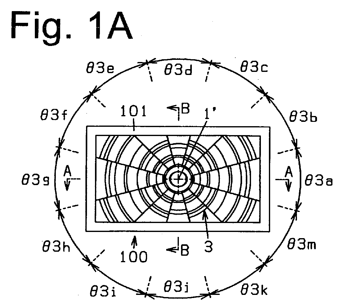
- Figs. 1A to 1C schematically show a vehicular lamp 100 according to a first exemplary embodiment.
- Figs. 1A, 1B, and 1C are a front view of the vehicular lamp 100 according to the first exemplary embodiment made in accordance with principles of the present invention, a horizontal cross-sectional view taken along line A-A in Fig. 1A including the optical axis 1' of a light source 1, and a vertical cross-sectional view taken along line B-B in Fig. 1A including the optical axis 1' of the light source 1, respectively.
- the guiding lens 3 can have a rectangular front shape as a polygonal shape when viewed in the optical axis 1' direction of the light source 1 (form the lower side in Fig. 1B and from left side in Fig. 1C ) with four sides AB, BC, CD, and DA and having a center at the optical axis 1'.
- the guiding lens 3 can be considered as to have a plurality of divided portions (12 in the illustrated example) 3a, 3b, 3c, 3d, 3e, 3f, 3g, 3h, 3i, 3j, 3k, and 3m virtually divided by a plurality of plains including the optical axis 1' of the light source 1.
- the divided portion 3a of the guiding lens 3 can further include an incidence face 3a2 (see Fig. 2C ) on which light emitted from the light source 1 at angles ⁇ a2, ⁇ a3, ⁇ a4, ⁇ a5, and ⁇ a6 with respect to the optical axis 1' (wherein ⁇ a1 ⁇ ⁇ a2 ⁇ ⁇ a3 ⁇ ⁇ a4 ⁇ ⁇ a5 ⁇ ⁇ a6).
- the light-exiting face 3a4b of the divided portion 3a can be configured such that almost all the light having passed through the light-exiting face 3a4b can become parallel with the optical axis 1' of the light source 1.
- the divided portion 3a of the guiding lens 3 can further include a reflection face 3a5c configured to reflect the light emitted from the light source 1 at the angle ⁇ a4 with respect to the optical axis 1' and having passed through the incidence face 3a2 (see Fig. 2C ), in the optical axis direction and a light-exiting face 3a4c through which the light from the reflection face 3a5c passes to be projected in the illumination direction of the vehicular lamp 100 (right upper side of Fig. 6A ).
- a reflection face 3a5c configured to reflect the light emitted from the light source 1 at the angle ⁇ a4 with respect to the optical axis 1' and having passed through the incidence face 3a2 (see Fig. 2C ), in the optical axis direction and a light-exiting face 3a4c through which the light from the reflection face 3a5c passes to be projected in the illumination direction of the vehicular lamp 100 (right upper side of Fig. 6A ).
- the light-exiting face 3a4e of the divided portion 3a can be configured such that part of the light having passed through the light-exiting face 3a4e can become parallel with the optical axis 1' and the remaining part of the light having passed through the light-exiting face 3a4e can become light travelling at a certain angle with respect to the optical axis 1'.
- the light-exiting face 3a4e of the divided portion 3a can be configured such that all the light having passed through the light-exiting face 3a4e can become light travelling at a certain angle with respect to the optical axis 1'.
- the outer-diameter side end 3a4a1 of the light-exiting face 3a4a of the divided portion 3a can be disposed at a farthest position from the optical axis 1' of the light source 1 in the plane S3a containing the optical axis 1' and the maximum radius portion P3a of the divided portion 3a.
- the light-exiting face 3b4e of the divided portion 3b can be configured such that part of the light having passed through the light-exiting face 3b4e can become parallel with the optical axis 1' and the remaining part of the light having passed through the light-exiting face 3b4e can become light travelling at a certain angle with respect to the optical axis 1'.
- the light-exiting face 3b4e of the divided portion 3b can be configured such that all the light having passed through the light-exiting face 3b4e can become light travelling at a certain angle with respect to the optical axis 1'.
- the divided portion 3b of the guiding lens 3 can further include light-exiting face-side connection faces 3b7a1 and 3b7a2 configured to connect the light-exiting face 3b4a with the light-exiting face 3b4b, light-exiting face-side connection faces 3b7b1 and 3b7b2 configured to connect the light-exiting face 3b4b with the light-exiting face 3b4c, light-exiting face-side connection faces 3b7c1 and 3b7c2 configured to connect the light-exiting face 3b4c with the reflection face 3b4d, light-exiting face-side connection faces 3b7d1 and 3b7d2 configured to connect the reflection face 3b4d with the reflection face 3b4e, a light-exiting face-side connection face 3b7e configured to connect the light-exiting face 3b4
- the outer-diameter side end 3b4a1 of the light-exiting face 3b4a of the divided portion 3b can be disposed at a farthest position from the optical axis 1' of the light source 1 in the plane S3b containing the optical axis 1' and the maximum radius portion P3b of the divided portion 3b.
- the light-exiting faces 3b3, 3b4a, 3b4b, 3b4c, 3b4d, 3b4e, and 3b4f can be seen to be bright when viewed from the front side in the optical axis direction (left upper side of Figs. 7A to 8B ).
- the cross-hatched portion as shown in Fig. 11A can be seen as if it is illuminated with light in the divided portion 3b.
- the light-exiting face 3c4b of the divided portion 3c can be configured such that part of the light having passed through the light-exiting face 3c4b can become parallel with the optical axis 1' and the remaining part of the light having passed through the light-exiting face 3c4b can become light travelling at a certain angle with respect to the optical axis 1'.
- the light-exiting face 3c4b of the divided portion 3c can be configured such that all the light having passed through the light-exiting face 3c4b can become light travelling at a certain angle with respect to the optical axis 1'.
- the divided portion 3d of the guiding lens 3 can further include a reflection face 3d5d configured to reflect the light emitted from the light source 1 at the angle ⁇ d5 with respect to the optical axis 1' and having passed through the incidence face 3d2 (see Fig. 5B ), in the optical axis direction and a light-exiting face 3d4d through which the light from the reflection face 3d5d passes to be projected in the illumination direction of the vehicular lamp 100 (left upper side of Fig. 10B ).
- a reflection face 3d5d configured to reflect the light emitted from the light source 1 at the angle ⁇ d5 with respect to the optical axis 1' and having passed through the incidence face 3d2 (see Fig. 5B ), in the optical axis direction and a light-exiting face 3d4d through which the light from the reflection face 3d5d passes to be projected in the illumination direction of the vehicular lamp 100 (left upper side of Fig. 10B ).
- the divided portion 3g adjacent to the divided portion 3f and the divided portion 3a can be configured to be line symmetric across the vertical plane VS. Accordingly, in the vehicular lamp 100 of the first exemplary embodiment, when the divided portion 3g of the guiding lens 3 is viewed from the optical axis direction of the light source 1 (lower side in Fig. 1B and left side in Fig. 1C ), the cross-hatched portion as shown in Fig. 11A can be seen as if it is illuminated with light in the divided portion 3g.
- the divided portion 3i adjacent to the divided portion 3h and the divided portion 3e can be configured to be line symmetric across the horizontal plane HS. Accordingly, in the vehicular lamp 100 of the first exemplary embodiment, when the divided portion 3i of the guiding lens 3 is viewed from the optical axis direction of the light source 1 (lower side in Fig. 1B and left side in Fig. 1C ), the cross-hatched portion as shown in Fig. 11A can be seen as if it is illuminated with light in the divided portion 3i.
- the divided portion 3m adjacent to the divided portion 3k and the divided portion 3b can be configured to be line symmetric across the horizontal plane HS. Accordingly, in the vehicular lamp 100 of the first exemplary embodiment, when the divided portion 3m of the guiding lens 3 is viewed from the optical axis direction of the light source 1 (lower side in Fig. 1B and left side in Fig. 1C ), the cross-hatched portion as shown in Fig. 11A can be seen as if it is illuminated with light in the divided portion 3m.
- the vehicular lamp 100 according to the first exemplary embodiment can be configured such that the area of the excess portion 3a" (see Fig. 2B ) is smaller than the area of the excess portion 3b" (see Fig. 3A ). Accordingly, the amount of light that is emitted from the light source 1 and enters the reflection face 3a5a of the divided portion 3a within the cross-section shown in Figs. 12A and 12B can be made smaller than that of the light that is emitted from the light source 1 and enters the reflection face 3b5a of the divided portion 3b within the cross-section shown in Figs. 13A and 13B .
- the reflection face 3a5a of the divided portion 3a and the reflection face 3b5a of the divided portion 3b are configured such that the difference between the first and second angles ( ⁇ a2b - ⁇ a2a) is equal to the difference between the third and fourth angles ( ⁇ b2b - ⁇ b2a)
- the light that passes through the light-exiting face 3b4a of the divided portion 3b and is reflected by the reflection face 3b5a of the divided portion 3b in the illuminating direction of the vehicular lamp 100 may be seen darker than the light that passes through the light-exiting face 3a4a of the divided portion 3a and is reflected by the reflection face 3a5a of the divided portion 3a in the illuminating direction of the vehicular lamp 100.
- the vehicular lamp 100 with the above configuration can avoid such a phenomenon.
- the light emitted rightward from the light source 1 at the angle ⁇ 1a with respect to the optical axis 1' of the light source 1 can pass through the incidence face 3a1 and the light-exiting face 3a3 of the divided portion 3a that is located at a position including the horizontal plane HS containing the optical axis 1', so that the exiting light becomes rightward light L1cR at the angle ⁇ 1c (wherein ⁇ 1b ⁇ ⁇ 1c) with respect to the optical axis 1'.
- the light-exiting faces 3a4b and 3a4g of the divided portions 3a and 3g located at the respective positions within the horizontal plane HS containing the optical axis 1' can be observed as if they are illuminated brighter.
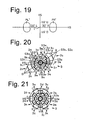
- the divided portion 3a can be formed, as shown in Fig. 20 , from part of a rotational body as a basic block obtained by rotating a cross-sectional shape appearing on a plane S3a can be rotated around the optical axis 1' by 22.5 degrees.
- the divided portion 3b can be formed from part of a rotational body as a basic block obtained by rotating a cross-sectional shape appearing on a plane S3b can be rotated around the optical axis 1' by 22.5 degrees.
- each of the divided portions 3d, 3f, 3h, 3j, and 3m can be configured to be almost the same shape as the divided portion 3b such that the divided portion 3d, 3f, 3h, 3j, or 3m and the divided portion 3b are rotationally symmetric about the optical axis 1' by 60 x n degrees (n is a natural number).
- the vehicular lamp according to the present invention can have a guiding lens 3 with any appropriate polygonal contour when viewed from the optical axis direction of the light source 1.
- the respective sides of the polygon can correspond to the divided portions 3a, 3b,,, and so.
- the vehicular lamp according to the present invention can be applied not only to a headlamp, a front fog lamp, and the like, but also to a stop lamp, a rear lamp, a turn signal lamp, a rear fog lamp, a day-time travelling lamp, and the like.
Landscapes
- Engineering & Computer Science (AREA)
- General Engineering & Computer Science (AREA)
- Physics & Mathematics (AREA)
- Microelectronics & Electronic Packaging (AREA)
- Optics & Photonics (AREA)
- Non-Portable Lighting Devices Or Systems Thereof (AREA)
Abstract
Description
- The present invention relates to a vehicular lamp having a light source including a light emitting device, and a guiding lens configured to guide light emitted from the light source. In particular, the present invention relates to a vehicular lamp having a guiding lens with a contour, when viewed from an optical axis direction of the light source, to be a polygon (with a plurality of sides) having a center on the optical axis.
- Furthermore, the present invention relates to a vehicular lamp having a guiding lens of which contour of polygon can be clearly viewed when the guiding lens is viewed from the optical axis direction of the light source.
- Still further, the present invention relates to a vehicular lamp that can improve the use efficiency of light emitted from the light source.
- Some conventional vehicular lamps have been known to include a light source with a light emitting device and a guiding lens (translucent member) configured to guide the light emitted from the light source. Examples of this type of vehicular lamp have been described in, for example, Japanese Patent Application Laid-Open No.
2005-203111 US Patent 7,270,454(B2 ) (hereinafter, referred to as Patent Literature 1), in particular,Figs. 1 to 3 . The vehicular lamp disclosed inPatent Literature 1 has a light source having a light emitting device with an optical axis extending horizontally. Light emitted from the light source can be guided by the guiding lens (translucent member) to be partially radiated in the optical axis direction of the light source. - In particular, the vehicular lamp described in
Figs. 1 to 3 of Patent Literature 1 includes the guiding lens (translucent member) having: a first incidence face on which the light emitted from the light source at a first angle with respect to the optical axis of the light source impinges; a first light-exiting face through which the light from the first incidence face passes to be projected in the illumination direction of the vehicular lamp; a second incidence face on which the light emitted from the light source at a second angle larger than the first angle with respect to the optical axis and the light emitted from the light source at a third angle larger than the second angle with respect to the optical axis impinge; a first reflection face configured to reflect the light emitted from the light source at the second angle and having passed through the second incidence face, in the optical axis direction of the light source; a second light-exiting face through which the light from the first reflection face passes to be projected in the illumination direction of the vehicular lamp; a second reflection face configured to reflect the light emitted from the light source at the third angle and having passed through the second incidence face, in the optical axis direction of the light source; a third light-exiting face through which the light from the second reflection face passes to be projected in the illumination direction of the vehicular lamp; a reflection face-side connection face configured to connect the first reflection face with the second reflection face; and a light-exiting face-side connection face configured to connect the second light-exiting face with the third light-exiting face. - In the vehicular lamp disclosed in
Figs. 1 to 3 ofPatent Literature 1, the contour of the guiding lens when viewed from the front side in the optical axis direction of the light source can be a circle. However, in order to enhance the aesthetic or designing value of a vehicular lamp, it may be required to form the guiding lens with a polygonal contour when viewed from the optical axis direction. - In order to comply with such a requirement, it is conceivable that such a guiding lens can be formed by the following designing process. Specifically, a rotational body for a guiding lens can be obtained by rotating a cross-section on a plane containing the optical axis of the light source around the optical axis by 360 degrees, and the rotational body is cut along a desired polygonal contour to obtain the desired guiding lens.
- When a guiding lens is formed by the above designing process, however, light-exiting face-side connection faces configured to connect a plurality of light-exiting faces may be located on a plurality of sides of the polygon at a higher possibility rather than the light-exiting faces themselves are located thereon. Since the light-exiting face-side connection faces cannot be seen to emit light when viewed from the front side in the optical axis direction, if the light-exiting face-side connection faces are located on the polygon sides at a high possibility, the polygon sides of the guiding lens may be seen darker at a high possibility when viewed from the front side in the optical axis direction. Accordingly, when the guiding lens is designed by the above designing process, the resulting guiding lens may have a blurred contour of the polygon of the guiding lens when viewed from the front side in the optical axis direction.
- Furthermore, this means that at the positions where the light-exiting face-side connection faces are located on the polygonal sides, there are no light-exiting faces configured to allow the light guided by the guiding lens to be projected therethrough in the illumination direction of the vehicular lamp. Accordingly, the light guided by the guiding lens to those positions cannot be projected in the illumination direction of the vehicular lamp. This may deteriorate the use efficiency of light emitted from the light source.
- The present invention was devised in view of these and other problems and features and in association with the conventional art. According to an aspect of the present invention, a vehicular lamp can be provided that can have a guiding lens with a clear contour of a polygon when viewed from the front side in the optical axis direction of the light source when compared with the case where the guiding lens is composed of a rotational body obtained by rotating a cross-sectional shape appearing on a plane containing the optical axis of the light source around the optical axis by 360 degrees, and cutting the body along a desired polygonal contour.
- According to another aspect of the present invention, a vehicular lamp can be provided that can enhance the use efficiency of light emitted from a light source when compared with the case where the guiding lens is composed of a rotational body obtained by rotating a cross-section on a plane containing the optical axis of the light source around the optical axis by 360 degrees, and cutting the body along a desired polygonal contour.
- According to still another aspect of the present invention, a vehicular lamp can include a light source having a light emitting device with an optical axis extending horizontally and a guiding lens configured to guide light emitted from the light source, wherein the light emitted from the light source can be guided by the guiding lens to be projected in a direction of the optical axis of the light source. The guiding lens can have a polygonal contour having N sides (where N is an integer of 3 or more) when viewed from a front side in the direction of the optical axis of the light source, the polygonal contour formed around the optical axis of the light source as a center. The guiding lens can be configured to include a plurality of divided portions obtained by virtually dividing the guiding lens with a plurality of planes containing the optical axis of the light source into n divided portions (n is an integer larger than N), and setting center angles of the respective divided portions around the optical axis of the light source as the center to (360/n) degrees. Each of the divided portions of the guiding lens can be composed of part of a rotational body obtained by rotating a cross-sectional shape appearing on a plane containing the optical axis of the light source and a maximum radius portion of the divided portion farthest from the center around the optical axis by 360/n degrees. Each of the divided portions of the guiding lens can be configured to include:
- a first incidence face on which the light emitted from the light source at a first angle with respect to the optical axis of the light source impinges;
- a first light-exiting face through which the light from the first incidence face passes to be projected in the illumination direction of the vehicular lamp;
- a second incidence face on which the light emitted from the light source at a second angle larger than the first angle with respect to the optical axis and the light emitted from the light source at a third angle larger than the second angle with respect to the optical axis impinge;
- a first reflection face configured to reflect the light emitted from the light source at the second angle with respect to the optical axis and having passed through the second incidence face, in the direction of the optical axis of the light source;
- a second light-exiting face through which the light from the first reflection face passes to be projected in the illumination direction of the vehicular lamp;
- a second reflection face configured to reflect the light emitted from the light source at the third angle with respect to the optical axis and having passed through the second incidence face, in the direction of the optical axis of the light source;
- a third light-exiting face through which the light from the second reflection face passes to be projected in the illumination direction of the vehicular lamp;
- a reflection face-side connection face configured to connect the first reflection face with the second reflection face; and
- a light-exiting face-side connection face configured to connect the second light-exiting face with the third light-exiting face.
- In this configuration, the second light-exiting face can be configured to include an outer-diameter side end disposed at a farthest position from the optical axis of the light source in the plane containing the optical axis of the light source and the maximum radius portion of the corresponding divided portion.
- In the vehicular lamp with the above configuration, when a first sector is obtained by rotating a segment, connecting the maximum radius portion of a first divided portion out of the divided portions to the optical axis, perpendicular to the optical axis by 360/n degrees around the optical axis as a center, and a second sector is obtained by rotating a segment, connecting the maximum radius portion of a second divided portion adjacent to the first divided portion to the optical axis, perpendicular to the optical axis by 360/n degrees around the optical axis as a center, if a difference area between the first sector and a projected area of the first divided portion when viewed from the front side in the direction of the optical axis is smaller than a difference area between the second sector and a projected area of the second divided portion when viewed from the front side in the direction of the optical axis, the first reflection face of the first divided portion and the first reflection face of the second divided portion can be configured such that a difference between a first angle and a second angle is smaller than a difference between a third angle and a fourth angle wherein the first angle is formed between the optical axis of the light source and the light impinging on an outer-diameter side end of the first reflection face of the first divided portion within the plane containing the maximum radius portion of the first divided portion and the optical axis of the light source, the second angle is formed between the optical axis of the light source and the light impinging on an inner-diameter side end of the first reflection face of the first divided portion within the plane containing the maximum radius portion of the first divided portion and the optical axis of the light source, the third angle is formed between the optical axis of the light source and the light impinging on an outer-diameter side end of the first reflection face of the second divided portion within the plane containing the maximum radius portion of the second divided portion and the optical axis of the light source, and the fourth angle is formed between the optical axis of the light source and the light impinging on an inner-diameter side end of the first reflection face of the second divided portion within the plane containing the maximum radius portion of the second divided portion and the optical axis of the light source.
- In the vehicular lamp with the above configuration, the first incidence faces of the respective divided portions can be each formed from a rotational plane obtained by rotating a curve around the optical axis of the light source as a center by 360 degrees. Furthermore, the first light-exiting faces of the respective divided portions can be configured
such that light emitted upward from the light source at an angle θ1a (wherein 0 < θ1a) with respect to the optical axis of the light source can pass through the first incidence face and the first light-exiting face of one divided portion that is located at a position including a vertical plane containing the optical axis of the light source so that the exiting light becomes upward light at an angle θ1b (wherein 0 < θ1b < θ1a) with respect to the optical axis of the light source,
such that light emitted downward from the light source at the angle θ1a with respect to the optical axis of the light source can pass through the first incidence face and the first light-exiting face of one divided portion that is located at a position including the vertical plane containing the optical axis of the light source so that the exiting light becomes downward light at the angle θ1b with respect to the optical axis of the light source,
such that light emitted rightward from the light source at the angle θ1a with respect to the optical axis of the light source can pass through the first incidence face and the first light-exiting face of one divided portion that is located at a position including a horizontal plane containing the optical axis of the light source so that the exiting light becomes rightward light at an angle θ1c (wherein θ1b < θ1c) with respect to the optical axis of the light source, and
such that light emitted leftward from the light source at the angle θ1a with respect to the optical axis of the light source can pass through the first incidence face and the first light-exiting face of one divided portion that is located at a position including the horizontal plane containing the optical axis of the light source so that the exiting light becomes leftward light at the angle θ1c with respect to the optical axis of the light source. - In the vehicular lamp with the above configuration, the divided portion that is located at the position within the horizontal plane containing the optical axis of the light source can be configured to include a third reflection face configured to reflect the light traveling from the second reflection face in the direction of the optical axis of the light source to guide the light at a certain angle with respect to the optical axis of the light source. In addition, part of the light from the third reflection face of the divided portion that is located at the position within the horizontal plane containing the optical axis of the light source can be allowed to pass through the third light-exiting face so that it becomes rightward or leftward light traveling within the horizontal plane at 45 degrees with respect to the optical axis of the light source.
- As described above, the vehicular lamp according to one of the aspects of the present invention can include a light source having a light emitting device and a guiding lens configured to guide light emitted from the light source. The optical axis of the light source can be disposed within the horizontal plane. Furthermore, the light emitted from the light source can be guided by the guiding lens, and part of the guided light can be projected in the optical axis direction of the light source.
- Specifically, in the vehicular lamp according to the one of the aspects, the contour of the guiding lens of the vehicular lamp can be a polygon having N sides (where N is an integer of 3 or more) when viewed from its front side in the optical axis direction. In this case, the polygon can be formed around the optical axis of the light source as a center. Further, the guiding lens can be configured to include n divided portions (blocks) virtually divided by a plurality of planes containing the optical axis where n is an integer larger than N. The center angles of the respective divided portions around the optical axis are set to (360/n) degrees.
- Further, in the vehicular lamp according to the one of the aspects, each of the divided portions can be composed of part of a rotational body obtained by rotating a cross-sectional shape around the optical axis by 360 degrees, with the cross-sectional shape appearing on a plane containing the optical axis and the maximum radius portion of the divided portion farthest from the center.
- Furthermore, in the vehicular lamp according to the one of the aspects, each of the divided portions can be configured to include: a first incidence face on which the light emitted from the light source at a first angle with respect to the optical axis impinges; a first light-exiting face through which the light from the first incidence face passes to be projected in the illumination direction of the vehicular lamp; a second incidence face on which the light emitted from the light source at a second angle larger than the first angle with respect to the optical axis and the light emitted from the light source at a third angle larger than the second angle with respect to the optical axis impinge; a first reflection face configured to reflect the light emitted from the light source at the second angle and having passed through the second incidence face, in the optical axis direction; a second light-exiting face through which the light from the first reflection face passes to be projected in the illumination direction; a second reflection face configured to reflect the light emitted from the light source at the third angle and having passed through the second incidence face, in the optical axis direction; a third light-exiting face through which the light from the second reflection face passes to be projected in the illumination direction; a reflection face-side connection face configured to connect the first reflection face with the second reflection face; and a light-exiting face-side connection face configured to connect the second light-exiting face with the third light-exiting face.
- Still further, in the vehicular lamp according to the one of the aspects, the outer-diameter side end of the second light-exiting face can be disposed at a farthest position from the optical axis in the plane containing the optical axis and the maximum radius portion of the corresponding divided portion.
- Accordingly, when compared with the case where the guiding lens is composed of a rotational body obtained by rotating a cross-sectional shape appearing on a plane containing the optical axis of the light source around the optical axis by 360 degrees, and cutting the body along a desired polygonal contour, the second light-exiting faces of the vehicular lamp according to the one of the aspects can be disposed on the N sides of the polygon at a high possibility. In other words, the vehicular lamp according to the one of the aspects can improve the ratio of the polygonal sides that can be seen to be bright when viewed from the front side in the optical axis direction when compared with the conventional vehicular lamp with the above configuration. This means that the guiding lens of the vehicular lamp can show a clear polygonal contour when viewed from the front side in the optical axis direction when compared with the conventional vehicular lamp with the above configuration.
- Furthermore, when compared with the case where the guiding lens is composed of a rotational body obtained by rotating a cross-sectional shape appearing on a plane containing the optical axis of the light source around the optical axis by 360 degrees, and cutting the body along a desired polygonal contour, the vehicular lamp according to the one of the aspects can reduce the ratio of light that cannot be projected in the illumination direction of the vehicular lamp out of the light emitted from the light source and impinging on the guiding lens. Specifically, the vehicular lamp according to the one of the aspects can enhance the use efficiency of light emitted from the light source when compared with the conventional vehicular lamp with the above configuration.
- In the vehicular lamp with the above configuration, suppose a case where a first sector is obtained by rotating a segment connecting the maximum radius portion of a first divided portion out of the divided portions to the optical axis perpendicular to the optical axis by (360/n) degrees around the optical axis as a center. Further, suppose that a second sector is obtained by rotating a segment connecting the maximum radius portion of a second divided portion adjacent to the first divided portion to the optical axis perpendicular to the optical axis by (360/n) degrees around the optical axis as a center. In this case, if a difference area between the first sector and a projected area of the first divided portion of the guiding lens when viewed from the front side in the optical axis direction is smaller than a difference area between the second sector and a projected area of the second divided portion of the guiding lens when viewed from the front side in the optical axis direction, the first reflection face of the first divided portion and the fist reflection face of the second divided portion can be configured such that the difference between a first angle and a second angle,is smaller than the difference between a third angle and a fourth angle. Herein, the first angle is formed between the optical axis and the light impinging on an outer-diameter side end of the first reflection face of the first divided portion within the plane containing the maximum radius portion of the first divided portion and the optical axis. Furthermore, the second angle is formed between the optical axis and the light impinging on an inner-diameter side end of the first reflection face of the first divided portion within the plane containing the maximum radius portion of the first divided portion and the optical axis. Still further, the third angle is formed between the optical axis and the light impinging on an outer-diameter side end of the first reflection face of the second divided portion within the plane containing the maximum radius portion of the second divided portion and the optical axis. Furthermore, the fourth angle is formed between the optical axis and the light impinging on an inner-diameter side end of the first reflection face of the second divided portion within a plane containing the maximum radius portion of the second divided portion and the optical axis.
- If the first reflection face of the first divided portion and the first reflection face of the second divided portion are configured such that the difference between the first and second angles is equal to the difference between the third and fourth angles, the light that passes through the second light-exiting face of the second divided portion and is reflected by the first reflection face of the second divided portion in the illuminating direction of the vehicular lamp can be seen darker than the light that passes through the second light-exiting face of the first divided portion and is reflected by the first reflection face of the first divided portion in the illuminating direction of the vehicular lamp. However, the vehicular lamp with the above configuration can avoid such a phenomenon.
- Namely, when compared with the case where the first reflection face of the first divided portion and the first reflection face of the second divided portion are configured such that the difference between the first and second angles is equal to the difference between the third and fourth angles, the respective sides of the polygon when viewed from the optical axis direction of the light source can be observed to be illuminated with a uniform brightness.
- In the vehicular lamp with the above configuration, the first incidence faces of the respective divided portions can be formed from a rotational plane obtained by rotating a curve around the optical axis of the light source as a center by 360 degrees.
- Furthermore, the first light-exiting faces of the respective divided portions can be configured as follows. Namely with this configuration, the light emitted upward from the light source at an angle θ1a (wherein 0 < θ1a) with respect to the optical axis can pass through the first incidence face and the first light-exiting face of one divided portion that is located at a position including a vertical plane containing the optical axis of the light source, so that the exiting light becomes upward light at an angle θ1b (wherein 0 < θ1b < θ1a) with respect to the optical axis. Further, the light emitted downward from the light source at the angle θ1a can pass through the first incidence face and the first light-exiting face of one divided portion that is located at a position including the vertical plane containing the optical axis, so that the exiting light becomes downward light at the angle θ1b with respect to the optical axis. Still further, the light emitted rightward from the light source at the angle θ1a can pass through the first incidence face and the first light-exiting face of one divided portion that is located at a position including a horizontal plane containing the optical axis, so that the exiting light becomes rightward light at an angle θ1c (wherein θ1b < θ1c) with respect to the optical axis. Still further, the light emitted leftward from the light source at the angle θ1a can pass through the first incidence face and the first light-exiting face of one divided portion that is located at a position including the horizontal plane containing the optical axis, so that the exiting light becomes leftward light at the angle θ1c with respect to the optical axis.
- Accordingly, in the above vehicular lamp, the light projected from the respective divided portions of the guiding lens through the respective first light-exiting faces in the illumination direction of the vehicular lamp can form a light distribution pattern (P) horizontally long.
- In the vehicular lamp with the above configuration, the divided portion that is located at the position including the horizontal plane containing the optical axis can include a third reflection face configured to reflect the light traveling from the second reflection face in the optical axis direction to guide the light at a certain angle with respect to the optical axis.
- In addition, part of the light from the third reflection face of the divided portion that is located at a position within the horizontal plane containing the optical axis can be allowed to pass through the third light-exiting face, so that the light becomes rightward or leftward light traveling within the horizontal plane at 45 degrees with respect to the optical axis.
- With this configuration, when the vehicular lamp is observed at a position that is on the extension of 45-degree line with respect to the optical axis, the third light-exiting faces of the divided portions located at the position within the horizontal plane containing the optical axis can be observed as if they are illuminated brighter.
- These and other characteristics, features, and advantages of the present invention will become clear from the following description with reference to the accompanying drawings, wherein:
-
Figs. 1A, 1B, and 1C are a front view of a vehicular lamp according to a first exemplary embodiment made in accordance with principles of the present invention, a horizontal cross-sectional view taken along line A-A inFig. 1A , and a vertical cross-sectional view taken along line B-B inFig. 1A , respectively; -
Figs. 2A is a front view of a guiding lens of the vehicular lamp according to the first exemplary embodiment,Fig. 2B is a front view of part (right side) of the guiding lens andFig. 2C is a cross-sectional view of the part of the guiding lens; -
Fig. 3A is a front view of another part (right corner) of the guiding lens of the vehicular lamp according to the first exemplary embodiment andFig. 3B is a cross-sectional view of the part of the guiding lens; -
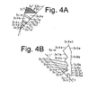
Fig. 4A is a front view of another part (right upper side) of the guiding lens of the vehicular lamp according to the first exemplary embodiment andFig. 4B is a cross-sectional view of the part of the guiding lens; -
Fig. 5A is a front view of another part (upper side) of the guiding lens of the vehicular lamp according to the first exemplary embodiment andFig. 5B is a cross-sectional view of the part of the guiding lens; -
Figs. 6A, 6B, and 6C are cross-sectional views of the part of the guiding lens inFig. 2C each showing the paths of light emitted from the light source and guided by the guiding lens at that part; -
Figs. 7A and 7B are cross-sectional views of the part of the guiding lens inFig. 3B each showing the paths of light emitted from the light source and guided by the guiding lens at that part; -
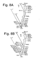
Figs. 8A and 8B are cross-sectional views of the part of the guiding lens inFig. 3B each showing the paths of light emitted from the light source and guided by the guiding lens at that part; -
Figs. 9A, 9B, and 9C are cross-sectional views of the part of the guiding lens inFig. 4B each showing the paths of light emitted from the light source and guided by the guiding lens at that part; -
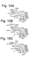
Figs. 10A, 10B, and 10C are cross-sectional views of the part of the guiding lens inFig. 5B each showing the paths of light emitted from the light source and guided by the guiding lens at that part; -
Fig. 11A is a front view of the guiding lens of the vehicular lamp according to the first exemplary embodiment andFig. 11B is a front view of a comparative guiding lens including a virtual portion around the guiding lens where the brighter portions are cross-hatched when the vehicular lamp is lit; -
Figs. 12A and 12B are cross-sectional views of the part of the guiding lens inFig. 2C each showing, in particular, reflection surfaces of that divided portion of the guiding lens; -
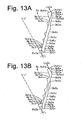
Figs. 13A and 13B are cross-sectional views of the part of the guiding lens inFig. 3B each showing, in particular, reflection surfaces of that divided portion of the guiding lens; -
Fig. 14A is a vertical cross-sectional view of the guiding lens showing the paths of light projected through light-exiting faces in the illumination direction, andFig. 14B is a horizontal cross-sectional view of the guiding lens showing the paths of light projected through light-exiting faces in the illumination direction; -
Fig. 15 shows a light distribution pattern formed by light having passed through light-exiting faces of the upper, lower, left and right side divided portions of the guiding lens; -
Fig. 16 is a horizontal cross-sectional view of the guiding lens showing the paths of light projected through left and right light-exiting faces in the illumination direction; -
Fig. 17 shows a light distribution pattern formed by light having passed through light-exiting faces of the left and right side divided portions of the guiding lens as a variation of the present exemplary embodiment; -
Fig. 18 is a horizontal cross-sectional view of the guiding lens showing the paths of light projected through left and right light-exiting faces in the illumination direction as another variation of the present exemplary embodiment; -
Fig. 19 shows a light distribution pattern formed by light having passed through light-exiting faces of the left and right side divided portions of the guiding lens as the variation of the present exemplary embodiment; -
Fig. 20 is a front view showing the guiding lens of a vehicular lamp according to a second exemplary embodiment; and -
Fig. 21 is a front view showing the guiding lens of a vehicular lamp according to a third exemplary embodiment. - A description will now be made below to vehicular lamps of the present invention with reference to the accompanying drawings in accordance with exemplary embodiments.
-
Figs. 1A to 1C schematically show avehicular lamp 100 according to a first exemplary embodiment. Specifically,Figs. 1A, 1B, and 1C are a front view of thevehicular lamp 100 according to the first exemplary embodiment made in accordance with principles of the present invention, a horizontal cross-sectional view taken along line A-A inFig. 1A including theoptical axis 1' of alight source 1, and a vertical cross-sectional view taken along line B-B inFig. 1A including theoptical axis 1' of thelight source 1, respectively. -
Figs. 2A to 5B illustrate a guidinglens 3 constituting thevehicular lamp 100 according to the first exemplary embodiment. Specifically,Fig. 2A is a front view of the guidinglens 3 of thevehicular lamp 100.Fig. 2B is a front view of part (a right side dividedportion 3a) of the guidinglens 3.Fig. 2C is a cross-sectional view of the dividedportion 3a within a plane S3a including a maximum radius portion P3a farthest from theoptical axis 1' of thelight source 1 and theoptical axis 1'.Fig. 3A is a front view of another part (a right corner dividedportion 3b) of the guidinglens 3.Fig. 3B is a cross-sectional view of the dividedportion 3b within a plane S3b including a maximum radius portion P3b farthest from theoptical axis 1' of thelight source 1 and theoptical axis 1'.Fig. 4A is a front view of another part (a right upper dividedportion 3c) of the guidinglens 3.Fig. 4B is a cross-sectional view of the dividedportion 3c within a plane S3c including a maximum radius portion P3c farthest from theoptical axis 1' of thelight source 1 and theoptical axis 1'.Fig. 5A is a front view of another part (an upper dividedportion 3d) of the guidinglens 3.Fig. 5B is a cross-sectional view of the dividedportion 3d within a plane S3d including a maximum radius portion P3d farthest from theoptical axis 1' of thelight source 1 and theoptical axis 1'. -
Figs. 6A, 6B, and 6C are cross-sectional views of the part (dividedportion 3a) of the guidinglens 3 inFig. 2C each showing the paths La1, La2, La3, La4, La5, and La6 of light emitted from thelight source 1 and guided by the dividedportion 3a of the guidinglens 3.Figs. 7A and 7B and8A and 8B are cross-sectional views of the part (dividedportion 3b) of the guidinglens 3 inFig. 3B each showing the paths Lb1, Lb2, Lb3, Lb4, Lb5, and Lb6 of light emitted from thelight source 1 and guided by the dividedportion 3b of the guidinglens 3.Figs. 9A, 9B, and 9C are cross-sectional views of the part (dividedportion 3c) of the guidinglens 3 inFig. 4B each showing the paths Lc1, Lc2, Lc3, Lc4, and Lc5 of light emitted from thelight source 1 and guided by the dividedportion 3c of the guidinglens 3.Figs. 10A, 10B, and 10C are cross-sectional views of the part (dividedportion 3d) of the guidinglens 3 inFig. 5B each showing the paths Ld1, Ld2, Ld3, Ld4, and Ld5 of light emitted from thelight source 1 and guided by the dividedportion 3d of the guidinglens 3. -
Fig. 11A is a front view of the guidinglens 3 of the vehicular lamp according to the first exemplary embodiment when viewed in the direction of theoptical axis 1' of thelight source 1 where the brighter portions are cross-hatched when the vehicular lamp is lit.Fig. 11B is a front view of the guidinglens 3 including a virtual portion around the guidinglens 3 where the brighter portions are cross-hatched when the vehicular lamp is lit. Specifically, the guidinglens 3 is composed of a part of a rotational body obtained by rotating a cross-sectional shape appearing on a plane containing theoptical axis 1' of thelight source 1 around theoptical axis 1' by 360 degrees, and cutting the body along a desired polygonal contour (rectangle in the illustrated example) and removing the virtual portion (hatched portion) in the drawing. - As shown in
Fig. 1 , thevehicular lamp 100 of the first exemplary embodiment can include thelight source 1 including a light emitting device such as an LED light source mounted on asubstrate 2, the guidinglens 3 configured to guide the light from thelight source 1, ahousing 101, and acover lens 102. Thelight source 1 and the guidinglens 3 can be housed within alamp chamber 103 defined by thehousing 101 and thecover lens 102. Theoptical axis 1' of thelight source 1 is disposed in a horizontal plane. It should be noted that in the present description and claims the upper, lower, right, left, front, and rear directions are based on the state where thevehicular lamp 100 is mounted in a vehicle body in a typical manner. - In the
vehicular lamp 100 of the first exemplary embodiment as shown inFig. 2A , the guidinglens 3 can have a rectangular front shape as a polygonal shape when viewed in theoptical axis 1' direction of the light source 1 (form the lower side inFig. 1B and from left side inFig. 1C ) with four sides AB, BC, CD, and DA and having a center at theoptical axis 1'. The guidinglens 3 can be considered as to have a plurality of divided portions (12 in the illustrated example) 3a, 3b, 3c, 3d, 3e, 3f, 3g, 3h, 3i, 3j, 3k, and 3m virtually divided by a plurality of plains including theoptical axis 1' of thelight source 1. Further, as shown inFigs. 1A and2A , the respective dividedportions optical axis 1' of thelight source 1, where the angle can be set to 30 degrees, for example. - Specifically, in the
vehicular lamp 100 of the first exemplary embodiment, as shown inFigs. 2B and 2C , the dividedportion 3a can be prepared in the following manner. Namely, a cross-sectional shape (seeFig. 2C ) appearing on a plane S3a (seeFig. 2B ) containing theoptical axis 1' of thelight source 1 and the maximum radius portion P3a (seeFig. 2B ) of the dividedportion 3a farthest from theoptical axis 1' or the center can be rotated around theoptical axis 1' by 30 degrees to form arotational body 3a' of sector top shape (seeFig. 2B ) as a basic block. The basic block or therotational body 3a' is cut along the side AB of the rectangle (seeFig. 2A ) so that theexcess portion 3a" over the contour of the rectangle (seeFig. 2B ) is removed, thereby forming the dividedportion 3a. - Furthermore, in the
vehicular lamp 100 of the first exemplary embodiment, as shown inFig. 6A , the dividedportion 3a of the guidinglens 3 can include an incidence face 3a1 (seeFig. 2C ) on which light emitted from thelight source 1 at an angle θa1 with respect to theoptical axis 1' of thelight source 1 impinges and a light-exiting face 3a3 through which the light from the incidence face 3a1 passes to be projected in the illumination direction of the vehicular lamp 100 (right upper side ofFig. 6A ). Specifically, in thevehicular lamp 100 of the first exemplary embodiment, as shown inFig. 6A , the light La1 that is emitted from thelight source 1 at the angle θa1 with respect to theoptical axis 1' and passes through the incidence face 3a1 and the light-exiting face 3a3 of the dividedportion 3a can be projected in the illumination direction of the vehicular lamp 100 (right upper side ofFig. 6A ). - In the
vehicular lamp 100 of the first exemplary embodiment, as shown inFigs. 6A to 6C , the dividedportion 3a of the guiding lens 3 (seeFig. 2A ) can further include an incidence face 3a2 (seeFig. 2C ) on which light emitted from thelight source 1 at angles θa2, θa3, θa4, θa5, and θa6 with respect to theoptical axis 1' (wherein θa1 < θa2 < θa3 < θa4 < θa5 < θa6). - In the
vehicular lamp 100 of the first exemplary embodiment, as shown inFig. 6B , the dividedportion 3a of the guiding lens 3 (seeFig. 2A ) can further include a reflection face 3a5a configured to reflect the light emitted from thelight source 1 at the angle θa2 with respect to theoptical axis 1' and having passed through the incidence face 3a2 (seeFig. 2C ), in the optical axis direction and a light-exiting face 3a4a through which the light from the reflection face 3a5a passes to be projected in the illumination direction of the vehicular lamp 100 (right upper side ofFig. 6B ). Specifically, in thevehicular lamp 100 of the first exemplary embodiment, as shown inFig. 6B , the light La2 that is emitted from thelight source 1 at the angle θa2 with respect to theoptical axis 1' and passes through the incidence face 3a2 of the dividedportion 3a, is reflected by the reflection face 3a5a, and passes through the light-exiting face 3a4a can be projected as parallel light in the illumination direction of the vehicular lamp 100 (right upper side ofFig. 6B ). Specifically, in thevehicular lamp 100 of the first exemplary embodiment, the light-exiting face 3a4a of the dividedportion 3a can be configured such that almost all the light having passed through the light-exiting face 3a4a can become parallel with theoptical axis 1' of thelight source 1. - In the
vehicular lamp 100 of the first exemplary embodiment, as shown inFig. 6C , the dividedportion 3a of the guiding lens 3 (seeFig. 2A ) can further include a reflection face 3a5b configured to reflect the light emitted from thelight source 1 at the angle θa3 with respect to theoptical axis 1' and having passed through the incidence face 3a2 (seeFig. 2C ), in the optical axis direction and a light-exiting face 3a4b through which the light from the reflection face 3a5b passes to be projected in the illumination direction of the vehicular lamp 100 (right upper side ofFig. 6C ). Specifically, in thevehicular lamp 100 of the first exemplary embodiment, as shown inFig. 6C , the light La3 that is emitted from thelight source 1 at the angle θa3 with respect to theoptical axis 1' and passes through the incidence face 3a2 of the dividedportion 3a, is reflected by the reflection face 3a5b, and passes through the light-exiting face 3a4b can be projected as parallel light in the illumination direction of the vehicular lamp 100 (right upper side ofFig. 6C ). Specifically, in thevehicular lamp 100 of the first exemplary embodiment, the light-exiting face 3a4b of the dividedportion 3a can be configured such that almost all the light having passed through the light-exiting face 3a4b can become parallel with theoptical axis 1' of thelight source 1. In one modified example of thevehicular lamp 100 of the first exemplary embodiment, the light-exiting face 3a4b of the dividedportion 3a can be configured such that part of the light having passed through the light-exiting face 3a4b can become parallel with theoptical axis 1' and the remaining part of the light having passed through the light-exiting face 3a4b can become light travelling at a certain angle with respect to theoptical axis 1'. In another modified example of thevehicular lamp 100 of the first exemplary embodiment, the light-exiting face 3a4b of the dividedportion 3a can be configured such that all the light having passed through the light-exiting face 3a4b can become light travelling at a certain angle with respect to theoptical axis 1'. - In the
vehicular lamp 100 of the first exemplary embodiment, as shown inFig. 6B , the dividedportion 3a of the guiding lens 3 (seeFig. 2A ) can further include a reflection face 3a5c configured to reflect the light emitted from thelight source 1 at the angle θa4 with respect to theoptical axis 1' and having passed through the incidence face 3a2 (seeFig. 2C ), in the optical axis direction and a light-exiting face 3a4c through which the light from the reflection face 3a5c passes to be projected in the illumination direction of the vehicular lamp 100 (right upper side ofFig. 6A ). Specifically, in thevehicular lamp 100 of the first exemplary embodiment, as shown inFig. 6A , the light La4 that is emitted from thelight source 1 at the angle θa4 with respect to theoptical axis 1' and passes through the incidence face 3a2 of the dividedportion 3a, is reflected by the reflection face 3a5c, and passes through the light-exiting face 3a4c can be projected as parallel light in the illumination direction of the vehicular lamp 100 (right upper side ofFig. 6A ). Specifically, in thevehicular lamp 100 of the first exemplary embodiment, the light-exiting face 3a4c of the dividedportion 3a can be configured such that almost all the light having passed through the light-exiting face 3a4c can become parallel with theoptical axis 1' of thelight source 1. In one modified example of thevehicular lamp 100 of the first exemplary embodiment, the light-exiting face 3a4c of the dividedportion 3a can be configured such that part of the light having passed through the light-exiting face 3a4c can become parallel with theoptical axis 1' and the remaining part of the light having passed through the light-exiting face 3a4c can become light travelling at a certain angle with respect to theoptical axis 1'. In another modified example of thevehicular lamp 100 of the first exemplary embodiment, the light-exiting face 3a4c of the dividedportion 3a can be configured such that all the light having passed through the light-exiting face 3a4c can become light travelling at a certain angle with respect to theoptical axis 1'. - In the
vehicular lamp 100 of the first exemplary embodiment, as shown inFig. 6B , the dividedportion 3a of the guiding lens 3 (seeFig. 2A ) can further include a reflection face 3a5d configured to reflect the light emitted from thelight source 1 at the angle θa5 with respect to theoptical axis 1' and having passed through the incidence face 3a2 (seeFig. 2C ), in the optical axis direction and a light-exiting face 3a4d through which the light from the reflection face 3a5d passes to be projected in the illumination direction of the vehicular lamp 100 (right upper side ofFig. 6B ). Specifically, in thevehicular lamp 100 of the first exemplary embodiment, as shown inFig. 6B , the light La5 that is emitted from thelight source 1 at the angle θa5 with respect to theoptical axis 1' and passes through the incidence face 3a2 of the dividedportion 3a, is reflected by the reflection face 3a5d, and passes through the light-exiting face 3a4d can be projected as parallel light in the illumination direction of the vehicular lamp 100 (right upper side ofFig. 6B ). Specifically, in thevehicular lamp 100 of the first exemplary embodiment, the light-exiting face 3a4d of the dividedportion 3a can be configured such that almost all the light having passed through the light-exiting face 3a4d can become parallel with theoptical axis 1' of thelight source 1. In one modified example of thevehicular lamp 100 of the first exemplary embodiment, the light-exiting face 3a4d of the dividedportion 3a can be configured such that part of the light having passed through the light-exiting face 3a4d can become parallel with theoptical axis 1' and the remaining part of the light having passed through the light-exiting face 3a4d can become light travelling at a certain angle with respect to theoptical axis 1'. In another modified example of thevehicular lamp 100 of the first exemplary embodiment, the light-exiting face 3a4d of the dividedportion 3a can be configured such that all the light having passed through the light-exiting face 3a4d can become light travelling at a certain angle with respect to theoptical axis 1'. - In the
vehicular lamp 100 of the first exemplary embodiment, as shown inFig. 6C , the dividedportion 3a of the guiding lens 3 (seeFig. 2A ) can further include a reflection face 3a5e configured to reflect the light emitted from thelight source 1 at the angle θa6 with respect to theoptical axis 1' and having passed through the incidence face 3a2 (seeFig. 2C ), in the optical axis direction and a light-exiting face 3a4e through which the light from the reflection face 3a5e passes to be projected in the illumination direction of the vehicular lamp 100 (right upper side ofFig. 6C ). Specifically, in thevehicular lamp 100 of the first exemplary embodiment, as shown inFig. 6C , the light La6 that is emitted from thelight source 1 at the angle θa6 with respect to theoptical axis 1' and passes through the incidence face 3a2 of the dividedportion 3a, is reflected by the reflection face 3a5e, and passes through the light-exiting face 3a4e can be projected as parallel light in the illumination direction of the vehicular lamp 100 (right upper side ofFig. 6C ). Specifically, in thevehicular lamp 100 of the first exemplary embodiment, the light-exiting face 3a4e of the dividedportion 3a can be configured such that almost all the light having passed through the light-exiting face 3a4e can become parallel with theoptical axis 1' of thelight source 1. In one modified example of thevehicular lamp 100 of the first exemplary embodiment, the light-exiting face 3a4e of the dividedportion 3a can be configured such that part of the light having passed through the light-exiting face 3a4e can become parallel with theoptical axis 1' and the remaining part of the light having passed through the light-exiting face 3a4e can become light travelling at a certain angle with respect to theoptical axis 1'. In another modified example of thevehicular lamp 100 of the first exemplary embodiment, the light-exiting face 3a4e of the dividedportion 3a can be configured such that all the light having passed through the light-exiting face 3a4e can become light travelling at a certain angle with respect to theoptical axis 1'. - In the
vehicular lamp 100 of the first exemplary embodiment, as shown inFig. 2C , the dividedportion 3a of the guiding lens 3 (seeFig. 2A ) can further include a reflection face-side connection face 3a6b configured to connect the reflection face 3a5a with the reflection face 3a5b, a reflection face-side connection face 3a6c configured to connect the reflection face 3a5b with the reflection face 3a5c, a reflection face-side connection face 3a6d configured to connect the reflection face 3a5c with the reflection face 3a5d, a reflection face-side connection face 3a6e configured to connect the reflection face 3a5d with the reflection face 3a5e, and reflection face-side connection faces 3a6a1 and 3a6a2 configured to connect the reflection face 3a4a with the reflection face 3a5a. - In the
vehicular lamp 100 of the first exemplary embodiment, as shown inFig. 2C , the dividedportion 3a of the guiding lens 3 (seeFig. 2A ) can further include light-exiting face-side connection faces 3a7a1 and 3a7a2 configured to connect the light-exiting face 3a4a with the light-exiting face 3a4b, light-exiting face-side connection faces 3a7b1 and 3a7b2 configured to connect the light-exiting face 3a4b with the light-exiting face 3a4c, light-exiting face-side connection faces 3a7c1 and 3a7c2 configured to connect the light-exiting face 3a4c with the reflection face 3a4d, a light-exiting face-side connection face 3a7d configured to connect the reflection face 3a4d with the reflection face 3a4e, and a light-exiting face-side connection face 3a7e configured to connect the light-exiting face 3a4e with the light-exiting face 3a3. - Specifically, in the
vehicular lamp 100 of the first exemplary embodiment, as shown inFigs. 2B and 2C , the outer-diameter side end 3a4a1 of the light-exiting face 3a4a of the dividedportion 3a can be disposed at a farthest position from theoptical axis 1' of thelight source 1 in the plane S3a containing theoptical axis 1' and the maximum radius portion P3a of the dividedportion 3a. - As a result, in the
vehicular lamp 100 of the first exemplary embodiment as shown inFigs. 6A to 6C , the light-exiting faces 3a3, 3a4a, 3a4b, 3a4c, 3a4d, and 3a4e can be seen to be bright when viewed from the front side in the optical axis direction (right upper side ofFigs. 6A to 6C ). Specifically, in thevehicular lamp 100 of the first exemplary embodiment, when the dividedportion 3a of the guiding lens 3 (seeFig. 2A ) is viewed from the optical axis direction of the light source 1 (right upper side ofFigs. 6A to 6C ), the cross-hatched portion as shown inFig. 11A can be seen as if it is illuminated with light in the dividedportion 3a. - Further, in the
vehicular lamp 100 of the first exemplary embodiment, as shown inFigs. 3A and 3B , the dividedportion 3b adjacent to the dividedportion 3a (seeFig. 2A ) can be prepared in the following manner. Namely, a cross-sectional shape (seeFig. 3B ) appearing on a plane S3b (seeFig. 3A ) containing theoptical axis 1' of thelight source 1 and the maximum radius portion P3b (seeFig. 3A ) of the dividedportion 3b farthest from theoptical axis 1' or the center can be rotated around theoptical axis 1' by 30 degrees to form arotational body 3b' of sector top shape (seeFig. 3A ) as a basic block. The basic block or therotational body 3b' is cut along the sides AB and BC of the rectangle (seeFig. 2A ) so that theexcess portions 3b" over the contour of the rectangle (seeFig. 3A ) is removed, thereby forming the dividedportion 3b. - Furthermore, in the
vehicular lamp 100 of the first exemplary embodiment, as shown inFig. 7A , the dividedportion 3b of the guidinglens 3 can include an incidence face 3b1 (seeFig. 3B ) on which light emitted from thelight source 1 at an angle θb1 with respect to theoptical axis 1' of thelight source 1 impinges and a light-exiting face 3b3 through which the light from the incidence face 3b1 passes to be projected in the illumination direction of the vehicular lamp 100 (left upper side ofFig. 7A ). Specifically, in thevehicular lamp 100 of the first exemplary embodiment, as shown inFig. 7A , the light Lb1 that is emitted from thelight source 1 at the angle θb1 with respect to theoptical axis 1' and passes through the incidence face 3b1 and the light-exiting face 3b3 of the dividedportion 3b can be projected in the illumination direction of the vehicular lamp 100 (left upper side ofFig. 7A ). - In the
vehicular lamp 100 of the first exemplary embodiment, as shown inFigs. 7A to 8B , the dividedportion 3b of the guiding lens 3 (seeFig. 2A ) can further include an incidence face 3b2 (seeFig. 3B ) on which light emitted from thelight source 1 at angles θb2, θb3, θb4, θb5, θb6, and θb7 with respect to theoptical axis 1' (wherein θb1 < θb2 < θb3 < θb4 < θb5 < θb6 < θb7). - In the
vehicular lamp 100 of the first exemplary embodiment, as shown inFig. 7B , the dividedportion 3b of the guiding lens 3 (seeFig. 2A ) can further include a reflection face 3b5a configured to reflect the light emitted from thelight source 1 at the angle θb2 with respect to theoptical axis 1' and having passed through the incidence face 3b2 (seeFig. 3B ), in the optical axis direction and a light-exiting face 3b4a through which the light from the reflection face 3b5a passes to be projected in the illumination direction of the vehicular lamp 100 (left upper side ofFig. 7B ). Specifically, in thevehicular lamp 100 of the first exemplary embodiment, as shown inFig. 7B , the light Lb2 that is emitted from thelight source 1 at the angle θb2 with respect to theoptical axis 1' and passes through the incidence face 3b2 of the dividedportion 3b, is reflected by the reflection face 3b5a, and passes through the light-exiting face 3b4a can be projected as parallel light in the illumination direction of the vehicular lamp 100 (left upper side ofFig. 7B ). Specifically, in thevehicular lamp 100 of the first exemplary embodiment, the light-exiting face 3b4a of the dividedportion 3b can be configured such that almost all the light having passed through the light-exiting face 3b4a can become parallel with theoptical axis 1' of thelight source 1. - In the
vehicular lamp 100 of the first exemplary embodiment, as shown inFig. 8A , the dividedportion 3b of the guiding lens 3 (seeFig. 2A ) can further include a reflection face 3b5b configured to reflect the light emitted from thelight source 1 at the angle θb3 with respect to theoptical axis 1' and having passed through the incidence face 3b2 (seeFig. 3B ), in the optical axis direction and a light-exiting face 3b4b through which the light from the reflection face 3b5b passes to be projected in the illumination direction of the vehicular lamp 100 (left upper side ofFig. 8A ). Specifically, in thevehicular lamp 100 of the first exemplary embodiment, as shown inFig. 8A , the light Lb3 that is emitted from thelight source 1 at the angle θb3 with respect to theoptical axis 1' and passes through the incidence face 3b2 of the dividedportion 3b, is reflected by the reflection face 3b5b, and passes through the light-exiting face 3b4b can be projected as parallel light in the illumination direction of the vehicular lamp 100 (left upper side ofFig. 8A ). Specifically, in thevehicular lamp 100 of the first exemplary embodiment, the light-exiting face 3b4b of the dividedportion 3b can be configured such that almost all the light having passed through the light-exiting face 3b4b can become parallel with theoptical axis 1' of thelight source 1. In one modified example of thevehicular lamp 100 of the first exemplary embodiment, the light-exiting face 3b4b of the dividedportion 3b can be configured such that part of the light having passed through the light-exiting face 3b4b can become parallel with theoptical axis 1' and the remaining part of the light having passed through the light-exiting face 3b4b can become light travelling at a certain angle with respect to theoptical axis 1'. In another modified example of thevehicular lamp 100 of the first exemplary embodiment, the light-exiting face 3b4b of the dividedportion 3b can be configured such that all the light having passed through the light-exiting face 3b4b can become light travelling at a certain angle with respect to theoptical axis 1'. - In the
vehicular lamp 100 of the first exemplary embodiment, as shown inFig. 8B , the dividedportion 3b of the guiding lens 3 (seeFig. 2A ) can further include a reflection face 3b5c configured to reflect the light emitted from thelight source 1 at the angle θb4 with respect to theoptical axis 1' and having passed through the incidence face 3b2 (seeFig. 3B ), in the optical axis direction and a light-exiting face 3b4c through which the light from the reflection face 3b5c passes to be projected in the illumination direction of the vehicular lamp 100 (left upper side ofFig. 8B ). Specifically, in thevehicular lamp 100 of the first exemplary embodiment, as shown inFig. 8B , the light Lb4 that is emitted from thelight source 1 at the angle θb4 with respect to theoptical axis 1' and passes through the incidence face 3b2 of the dividedportion 3b, is reflected by the reflection face 3b5c, and passes through the light-exiting face 3b4c can be projected as parallel light in the illumination direction of the vehicular lamp 100 (left upper side ofFig. 8B ). Specifically, in thevehicular lamp 100 of the first exemplary embodiment, the light-exiting face 3b4c of the dividedportion 3b can be configured such that almost all the light having passed through the light-exiting face 3b4c can become parallel with theoptical axis 1' of thelight source 1. In one modified example of thevehicular lamp 100 of the first exemplary embodiment, the light-exiting face 3b4c of the dividedportion 3b can be configured such that part of the light having passed through the light-exiting face 3b4c can become parallel with theoptical axis 1' and the remaining part of the light having passed through the light-exiting face 3b4c can become light travelling at a certain angle with respect to theoptical axis 1'. In another modified example of thevehicular lamp 100 of the first exemplary embodiment, the light-exiting face 3b4c of the dividedportion 3b can be configured such that all the light having passed through the light-exiting face 3b4c can become light travelling at a certain angle with respect to theoptical axis 1'. - In the
vehicular lamp 100 of the first exemplary embodiment, as shown inFig. 7A , the dividedportion 3b of the guiding lens 3 (seeFig. 2A ) can further include a reflection face 3b5d configured to reflect the light emitted from thelight source 1 at the angle θb5 with respect to theoptical axis 1' and having passed through the incidence face 3b2 (seeFig. 3B ), in the optical axis direction and a light-exiting face 3b4d through which the light from the reflection face 3b5d passes to be projected in the illumination direction of the vehicular lamp 100 (left upper side ofFig. 7A ). Specifically, in thevehicular lamp 100 of the first exemplary embodiment, as shown inFig. 7A , the light Lb5 that is emitted from thelight source 1 at the angle θb5 with respect to theoptical axis 1' and passes through the incidence face 3b2 of the dividedportion 3b, is reflected by the reflection face 3b5d, and passes through the light-exiting face 3b4d can be projected as parallel light in the illumination direction of the vehicular lamp 100 (left upper side ofFig. 7A ). Specifically, in thevehicular lamp 100 of the first exemplary embodiment, the light-exiting face 3b4d of the dividedportion 3b can be configured such that almost all the light having passed through the light-exiting face 3b4d can become parallel with theoptical axis 1' of thelight source 1. In one modified example of thevehicular lamp 100 of the first exemplary embodiment, the light-exiting face 3b4d of the dividedportion 3b can be configured such that part of the light having passed through the light-exiting face 3b4d can become parallel with theoptical axis 1' and the remaining part of the light having passed through the light-exiting face 3b4d can become light travelling at a certain angle with respect to theoptical axis 1'. In another modified example of thevehicular lamp 100 of the first exemplary embodiment, the light-exiting face 3b4d of the dividedportion 3b can be configured such that all the light having passed through the light-exiting face 3b4d can become light travelling at a certain angle with respect to theoptical axis 1'. - In the
vehicular lamp 100 of the first exemplary embodiment, as shown inFig. 7B , the dividedportion 3b of the guiding lens 3 (seeFig. 2A ) can further include a reflection face 3b5e configured to reflect the light emitted from thelight source 1 at an angle θb6 with respect to theoptical axis 1' and having passed through the incidence face 3b2 (seeFig. 3B ), in the optical axis direction and a light-exiting face 3b4e through which the light from the reflection face 3b5e passes to be projected in the illumination direction of the vehicular lamp 100 (left upper side ofFig. 7B ). Specifically, in thevehicular lamp 100 of the first exemplary embodiment, as shown inFig. 7B , the light Lb6 that is emitted from thelight source 1 at the angle θb6 with respect to theoptical axis 1' and passes through the incidence face 3b2 of the dividedportion 3b, is reflected by the reflection face 3b5e, and passes through the light-exiting face 3b4e can be projected as parallel light in the illumination direction of the vehicular lamp 100 (left upper side ofFig. 7B ). Specifically, in thevehicular lamp 100 of the first exemplary embodiment, the light-exiting face 3b4e of the dividedportion 3b can be configured such that almost all the light having passed through the light-exiting face 3b4e can become parallel with theoptical axis 1' of thelight source 1. In one modified example of thevehicular lamp 100 of the first exemplary embodiment, the light-exiting face 3b4e of the dividedportion 3b can be configured such that part of the light having passed through the light-exiting face 3b4e can become parallel with theoptical axis 1' and the remaining part of the light having passed through the light-exiting face 3b4e can become light travelling at a certain angle with respect to theoptical axis 1'. In another modified example of thevehicular lamp 100 of the first exemplary embodiment, the light-exiting face 3b4e of the dividedportion 3b can be configured such that all the light having passed through the light-exiting face 3b4e can become light travelling at a certain angle with respect to theoptical axis 1'. - In the
vehicular lamp 100 of the first exemplary embodiment, as shown inFig. 8B , the dividedportion 3b of the guiding lens 3 (seeFig. 2A ) can further include a reflection face 3b5f configured to reflect the light emitted from thelight source 1 at an angle θb7 with respect to theoptical axis 1' and having passed through the incidence face 3b2 (seeFig. 3B ), in the optical axis direction and a light-exiting face 3b4f through which the light from the reflection face 3b5f passes to be projected in the illumination direction of the vehicular lamp 100 (left upper side ofFig. 8A ). Specifically, in thevehicular lamp 100 of the first exemplary embodiment, as shown inFig. 8A , the light Lb7 that is emitted from thelight source 1 at the angle θb7 with respect to theoptical axis 1' and passes through the incidence face 3b2 of the dividedportion 3b, is reflected by the reflection face 3b5f, and passes through the light-exiting face 3b4f can be projected as parallel light in the illumination direction of the vehicular lamp 100 (left upper side ofFig. 8A ). Specifically, in thevehicular lamp 100 of the first exemplary embodiment, the light-exiting face 3b4f of the dividedportion 3b can be configured such that almost all the light having passed through the light-exiting face 3b4f can become parallel with theoptical axis 1' of thelight source 1. In one modified example of thevehicular lamp 100 of the first exemplary embodiment, the light-exiting face 3b4f of the dividedportion 3b can be configured such that part of the light having passed through the light-exiting face 3b4f can become parallel with theoptical axis 1' and the remaining part of the light having passed through the light-exiting face 3b4f can become light travelling at a certain angle with respect to theoptical axis 1'. In another modified example of thevehicular lamp 100 of the first exemplary embodiment, the light-exiting face 3b4f of the dividedportion 3b can be configured such that all the light having passed through the light-exiting face 3b4f can become light travelling at a certain angle with respect to theoptical axis 1'. - In the
vehicular lamp 100 of the first exemplary embodiment, as shown inFig. 3B , the dividedportion 3b of the guiding lens 3 (seeFig. 2A ) can further include a reflection face-side connection face 3b6b configured to connect the reflection face 3b5a with the reflection face 3b5b, a reflection face-side connection face 3b6c configured to connect the reflection face 3b5b with the reflection face 3b5c, a reflection face-side connection face 3b6d configured to connect the reflection face 3b5c with the reflection face 3b5d, a reflection face-side connection face 3b6e configured to connect the reflection face 3b5d with the reflection face 3b5e, and a reflection face-side connection face 3b6a configured to connect the reflection face 3b4a with the reflection face 3b5a. - In the
vehicular lamp 100 of the first exemplary embodiment, as shown inFig. 3B , the dividedportion 3b of the guiding lens 3 (seeFig. 2A ) can further include light-exiting face-side connection faces 3b7a1 and 3b7a2 configured to connect the light-exiting face 3b4a with the light-exiting face 3b4b, light-exiting face-side connection faces 3b7b1 and 3b7b2 configured to connect the light-exiting face 3b4b with the light-exiting face 3b4c, light-exiting face-side connection faces 3b7c1 and 3b7c2 configured to connect the light-exiting face 3b4c with the reflection face 3b4d, light-exiting face-side connection faces 3b7d1 and 3b7d2 configured to connect the reflection face 3b4d with the reflection face 3b4e, a light-exiting face-side connection face 3b7e configured to connect the light-exiting face 3b4e with the light-exiting face 3b4f, and a light-exiting face-side connection face 3b7f configured to connect the light-exiting face 3b4f with the light-exiting face 3b3. - Specifically, in the
vehicular lamp 100 of the first exemplary embodiment, as shown inFigs. 3A and 3B , the outer-diameter side end 3b4a1 of the light-exiting face 3b4a of the dividedportion 3b can be disposed at a farthest position from theoptical axis 1' of thelight source 1 in the plane S3b containing theoptical axis 1' and the maximum radius portion P3b of the dividedportion 3b. - As a result, in the
vehicular lamp 100 of the first exemplary embodiment as shown inFigs. 7A to 8B , the light-exiting faces 3b3, 3b4a, 3b4b, 3b4c, 3b4d, 3b4e, and 3b4f can be seen to be bright when viewed from the front side in the optical axis direction (left upper side ofFigs. 7A to 8B ). Specifically, in thevehicular lamp 100 of the first exemplary embodiment, when the dividedportion 3b of the guiding lens 3 (seeFig. 2A ) is viewed from the optical axis direction of the light source 1 (left upper side ofFigs. 7A to 8B ), the cross-hatched portion as shown inFig. 11A can be seen as if it is illuminated with light in the dividedportion 3b. - Further, in the
vehicular lamp 100 of the first exemplary embodiment, as shown inFigs. 4A and 4B , the dividedportion 3c adjacent to the dividedportion 3b (seeFig. 2A ) can be prepared in the following manner. Namely, a cross-sectional shape (seeFig. 4B ) appearing on a plane S3c (seeFig. 4A ) containing theoptical axis 1' of thelight source 1 and the maximum radius portion P3c (seeFig. 4A ) of the dividedportion 3c farthest from theoptical axis 1' or the center can be rotated around theoptical axis 1' by 30 degrees to form arotational body 3c' of sector top shape (seeFig. 4A ) as a basic block. The basic block or therotational body 3c' is cut along the side BC of the rectangle (seeFig. 2A ) so that theexcess portion 3c" over the contour of the rectangle (seeFig. 4A ) is removed, thereby forming the dividedportion 3c. - Furthermore, in the
vehicular lamp 100 of the first exemplary embodiment, as shown inFig. 9A , the dividedportion 3c of the guidinglens 3 can include an incidence face 3c1 (seeFig. 4B ) on which light emitted from thelight source 1 at an angle θc1 with respect to theoptical axis 1' of thelight source 1 impinges and a light-exiting face 3c3 through which the light from the incidence face 3c1 passes to be projected in the illumination direction of the vehicular lamp 100 (left upper side ofFig. 9A ). Specifically, in thevehicular lamp 100 of the first exemplary embodiment, as shown inFig. 9A , the light Lc1 that is emitted from thelight source 1 at the angle θc1 with respect to theoptical axis 1' and passes through the incidence face 3c1 and the light-exiting face 3c3 of the dividedportion 3c can be projected in the illumination direction of the vehicular lamp 100 (left upper side ofFig. 9A ). - In the
vehicular lamp 100 of the first exemplary embodiment, as shown inFigs. 9A to 9C , the dividedportion 3c of the guiding lens 3 (seeFig. 2A ) can further include an incidence face 3c2 (seeFig. 4B ) on which light emitted from thelight source 1 at angles θc2, θc3, θc4, and θc5 with respect to theoptical axis 1' (wherein θc1 < θc2 < θc3 < θc4 < θc5). - In the
vehicular lamp 100 of the first exemplary embodiment, as shown inFig. 9B , the dividedportion 3c of the guiding lens 3 (seeFig. 2A ) can further include a reflection face 3c5a configured to reflect the light emitted from thelight source 1 at the angle θc2 with respect to theoptical axis 1' and having passed through the incidence face 3c2 (seeFig. 4B ), in the optical axis direction and a light-exiting face 3c4a through which the light from the reflection face 3c5a passes to be projected in the illumination direction of the vehicular lamp 100 (left upper side ofFig. 9B ). Specifically, in thevehicular lamp 100 of the first exemplary embodiment, as shown inFig. 9B , the light Lc2 that is emitted from thelight source 1 at the angle θc2 with respect to theoptical axis 1' and passes through the incidence face 3c2 of the dividedportion 3c, is reflected by the reflection face 3c5a, and passes through the light-exiting face 3c4a can be projected as parallel light in the illumination direction of the vehicular lamp 100 (left upper side ofFig. 9B ). Specifically, in thevehicular lamp 100 of the first exemplary embodiment, the light-exiting face 3c4a of the dividedportion 3c can be configured such that almost all the light having passed through the light-exiting face 3c4a can become parallel with theoptical axis 1' of thelight source 1. - In the
vehicular lamp 100 of the first exemplary embodiment, as shown inFig. 9C , the dividedportion 3c of the guiding lens 3 (seeFig. 2A ) can further include a reflection face 3c5b configured to reflect the light emitted from thelight source 1 at the angle θc3 with respect to theoptical axis 1' and having passed through the incidence face 3c2 (seeFig. 4B ), in the optical axis direction and a light-exiting face 3c4b through which the light from the reflection face 3c5b passes to be projected in the illumination direction of the vehicular lamp 100 (left upper side ofFig. 9C ). Specifically, in thevehicular lamp 100 of the first exemplary embodiment, as shown inFig. 9C , the light Lc3 that is emitted from thelight source 1 at the angle θc3 with respect to theoptical axis 1' and passes through the incidence face 3c2 of the dividedportion 3c, is reflected by the reflection face 3c5b, and passes through the light-exiting face 3c4b can be projected as parallel light in the illumination direction of the vehicular lamp 100 (left upper side ofFig. 9C ). Specifically, in thevehicular lamp 100 of the first exemplary embodiment, the light-exiting face 3c4b of the dividedportion 3c can be configured such that almost all the light having passed through the light-exiting face 3c4b can become parallel with theoptical axis 1' of thelight source 1. In one modified example of thevehicular lamp 100 of the first exemplary embodiment, the light-exiting face 3c4b of the dividedportion 3c can be configured such that part of the light having passed through the light-exiting face 3c4b can become parallel with theoptical axis 1' and the remaining part of the light having passed through the light-exiting face 3c4b can become light travelling at a certain angle with respect to theoptical axis 1'. In another modified example of thevehicular lamp 100 of the first exemplary embodiment, the light-exiting face 3c4b of the dividedportion 3c can be configured such that all the light having passed through the light-exiting face 3c4b can become light travelling at a certain angle with respect to theoptical axis 1'. - In the
vehicular lamp 100 of the first exemplary embodiment, as shown inFig. 9A , the dividedportion 3c of the guiding lens 3 (seeFig. 2A ) can further include a reflection face 3c5c configured to reflect the light emitted from thelight source 1 at the angle θc4 with respect to theoptical axis 1' and having passed through the incidence face 3c2 (seeFig. 4B ), in the optical axis direction and a light-exiting face 3c4c through which the light from the reflection face 3c5c passes to be projected in the illumination direction of the vehicular lamp 100 (left upper side ofFig. 9A ). Specifically, in thevehicular lamp 100 of the first exemplary embodiment, as shown inFig. 9A , the light Lc4 that is emitted from thelight source 1 at the angle θc4 with respect to theoptical axis 1' and passes through the incidence face 3c2 of the dividedportion 3c, is reflected by the reflection face 3c5c, and passes through the light-exiting face 3c4c can be projected as parallel light in the illumination direction of the vehicular lamp 100 (left upper side ofFig. 9A ). Specifically, in thevehicular lamp 100 of the first exemplary embodiment, the light-exiting face 3c4c of the dividedportion 3c can be configured such that almost all the light having passed through the light-exiting face 3c4c can become parallel with theoptical axis 1' of thelight source 1. In one modified example of thevehicular lamp 100 of the first exemplary embodiment, the light-exiting face 3c4c of the dividedportion 3c can be configured such that part of the light having passed through the light-exiting face 3c4c can become parallel with theoptical axis 1' and the remaining part of the light having passed through the light-exiting face 3c4c can become light travelling at a certain angle with respect to theoptical axis 1'. In another modified example of thevehicular lamp 100 of the first exemplary embodiment, the light-exiting face 3c4c of the dividedportion 3c can be configured such that all the light having passed through the light-exiting face 3c4c can become light travelling at a certain angle with respect to theoptical axis 1'. - In the
vehicular lamp 100 of the first exemplary embodiment, as shown inFig. 9B , the dividedportion 3c of the guiding lens 3 (seeFig. 2A ) can further include a reflection face 3c5d configured to reflect the light emitted from thelight source 1 at the angle θc5 with respect to theoptical axis 1' and having passed through the incidence face 3c2 (seeFig. 4B ), in the optical axis direction and a light-exiting face 3c4d through which the light from the reflection face 3c5d passes to be projected in the illumination direction of the vehicular lamp 100 (left upper side ofFig. 9B ). Specifically, in thevehicular lamp 100 of the first exemplary embodiment, as shown inFig. 9B , the light Lc5 that is emitted from thelight source 1 at the angle θc5 with respect to theoptical axis 1' and passes through the incidence face 3c2 of the dividedportion 3c, is reflected by the reflection face 3c5d, and passes through the light-exiting face 3c4d can be projected as parallel light in the illumination direction of the vehicular lamp 100 (left upper side ofFig. 9B ). Specifically, in thevehicular lamp 100 of the first exemplary embodiment, the light-exiting face 3c4d of the dividedportion 3c can be configured such that almost all the light having passed through the light-exiting face 3c4d can become parallel with theoptical axis 1' of thelight source 1. In one modified example of thevehicular lamp 100 of the first exemplary embodiment, the light-exiting face 3c4d of the dividedportion 3c can be configured such that part of the light having passed through the light-exiting face 3c4d can become parallel with theoptical axis 1' and the remaining part of the light having passed through the light-exiting face 3c4d can become light travelling at a certain angle with respect to theoptical axis 1'. In another modified example of thevehicular lamp 100 of the first exemplary embodiment, the light-exiting face 3c4d of the dividedportion 3c can be configured such that all the light having passed through the light-exiting face 3c4d can become light travelling at a certain angle with respect to theoptical axis 1'. - In the
vehicular lamp 100 of the first exemplary embodiment, as shown inFig. 4B , the dividedportion 3c of the guiding lens 3 (seeFig. 2A ) can further include a reflection face-side connection face 3c6b configured to connect the reflection face 3c5a with the reflection face 3c5b, a reflection face-side connection face 3c6c configured to connect the reflection face 3c5b with the reflection face 3c5c, and a reflection face-side connection face 3c6d configured to connect the reflection face 3c5c with the reflection face 3c5d. - In the
vehicular lamp 100 of the first exemplary embodiment, as shown inFig. 4B , the dividedportion 3c of the guiding lens 3 (seeFig. 2A ) can further include a light-exiting face-side connection face 3c7a configured to connect the light-exiting face 3c4a with the light-exiting face 3c4b, light-exiting face-side connection faces 3c7b1 and 3c7b2 configured to connect the light-exiting face 3c4b with the light-exiting face 3c4c, a light-exiting face-side connection face 3c7c configured to connect the light-exiting face 3c4c with the reflection face 3c4d, and a light-exiting face-side connection faces 3c7d configured to connect the reflection face 3c4d with the reflection face 3c3. - Specifically, in the
vehicular lamp 100 of the first exemplary embodiment, as shown inFigs. 4A and 4B , the outer-diameter side end 3c4a1 of the light-exiting face 3c4a of the dividedportion 3c can be disposed at a farthest position from theoptical axis 1' of thelight source 1 in the plane S3c containing theoptical axis 1' and the maximum radius portion P3c of the dividedportion 3c. - As a result, in the
vehicular lamp 100 of the first exemplary embodiment as shown inFigs. 9A to 9C , the light-exiting faces 3c3, 3c4a, 3c4b, 3c4c, and 3c4d can be seen to be bright when viewed from the front side in the optical axis direction (left upper side ofFigs. 9A to 9C ). Specifically, in thevehicular lamp 100 of the first exemplary embodiment, when the dividedportion 3c of the guiding lens 3 (seeFig. 2A ) is viewed from the optical axis direction of the light source 1 (left upper side ofFigs. 9A to 9C ), the cross-hatched portion as shown inFig. 11A can be seen as if it is illuminated with light in the dividedportion 3c. - Further, in the
vehicular lamp 100 of the first exemplary embodiment, as shown inFigs. 5A and 5B , the dividedportion 3d adjacent to the dividedportion 3c (seeFig. 2A ) can be prepared in the following manner. Namely, a cross-sectional shape (seeFig. 5B ) appearing on a plane S3d (seeFig. 5A ) containing theoptical axis 1' of thelight source 1 and the maximum radius portion P3d (seeFig. 5A ) of the dividedportion 3d farthest from theoptical axis 1' or the center can be rotated around theoptical axis 1' by 30 degrees to form arotational body 3d' of sector top shape (seeFig. 5A ) as a basic block. The basic block or therotational body 3d' is cut along the side BC of the rectangle (seeFig. 2A ) so that theexcess portion 3d" over the contour of the rectangle (seeFig. 5A ) is removed, thereby forming the dividedportion 3d. - Furthermore, in the
vehicular lamp 100 of the first exemplary embodiment, as shown inFig. 10A , the dividedportion 3d of the guidinglens 3 can include an incidence face 3d1 (seeFig. 5B ) on which light emitted from thelight source 1 at an angle θd1 with respect to theoptical axis 1' of thelight source 1 impinges and a light-exiting face 3d3 through which the light from the incidence face 3d1 passes to be projected in the illumination direction of the vehicular lamp 100 (left upper side ofFig. 10A ). Specifically, in thevehicular lamp 100 of the first exemplary embodiment, as shown inFig. 10A , the light Ld1 that is emitted from thelight source 1 at the angle θd1 with respect to theoptical axis 1' and passes through the incidence face 3d1 and the light-exiting face 3d3 of the dividedportion 3d can be projected in the illumination direction of the vehicular lamp 100 (left upper side ofFig. 10A ). - In the
vehicular lamp 100 of the first exemplary embodiment, as shown inFigs. 10A to 10C , the dividedportion 3d of the guiding lens 3 (seeFig. 2A ) can further include an incidence face 3d2 (seeFig. 5B ) on which light emitted from thelight source 1 at angles θd2, θd3, θd4, and θd5 with respect to theoptical axis 1' (wherein θd1 < θd2 < θd3 < θd4 < θd5). - In the
vehicular lamp 100 of the first exemplary embodiment, as shown inFig. 10B , the dividedportion 3d of the guiding lens 3 (seeFig. 2A ) can further include a reflection face 3d5a configured to reflect the light emitted from thelight source 1 at the angle θd2 with respect to theoptical axis 1' and having passed through the incidence face 3d2 (seeFig. 5B ), in the optical axis direction and a light-exiting face 3d4a through which the light from the reflection face 3d5a passes to be projected in the illumination direction of the vehicular lamp 100 (left upper side ofFig. 10B ). Specifically, in thevehicular lamp 100 of the first exemplary embodiment, as shown inFig. 10B , the light Ld2 that is emitted from thelight source 1 at the angle θd2 with respect to theoptical axis 1' and passes through the incidence face 3d2 of the dividedportion 3d, is reflected by the reflection face 3d5a, and passes through the light-exiting face 3d4a can be projected as parallel light in the illumination direction of the vehicular lamp 100 (left upper side ofFig. 10B ). Specifically, in thevehicular lamp 100 of the first exemplary embodiment, the light-exiting face 3d4a of the dividedportion 3d can be configured such that almost all the light having passed through the light-exiting face 3d4a can become parallel with theoptical axis 1' of thelight source 1. - In the
vehicular lamp 100 of the first exemplary embodiment, as shown inFig. 10C , the dividedportion 3d of the guiding lens 3 (seeFig. 2A ) can further include a reflection face 3d5b configured to reflect the light emitted from thelight source 1 at the angle θd3 with respect to theoptical axis 1' and having passed through the incidence face 3d2 (seeFig. 5B ), in the optical axis direction and a light-exiting face 3d4b through which the light from the reflection face 3d5b passes to be projected in the illumination direction of the vehicular lamp 100 (left upper side ofFig. 10C ). Specifically, in thevehicular lamp 100 of the first exemplary embodiment, as shown inFig. 10C , the light Ld3 that is emitted from thelight source 1 at the angle θd3 with respect to theoptical axis 1' and passes through the incidence face 3d2 of the dividedportion 3d, is reflected by the reflection face 3d5b, and passes through the light-exiting face 3d4b can be projected as parallel light in the illumination direction of the vehicular lamp 100 (left upper side ofFig. 10C ). Specifically, in thevehicular lamp 100 of the first exemplary embodiment, the light-exiting face 3d4b of the dividedportion 3d can be configured such that almost all the light having passed through the light-exiting face 3d4b can become parallel with theoptical axis 1' of thelight source 1. In one modified example of thevehicular lamp 100 of the first exemplary embodiment, the light-exiting face 3d4b of the dividedportion 3d can be configured such that part of the light having passed through the light-exiting face 3d4b can become parallel with theoptical axis 1' and the remaining part of the light having passed through the light-exiting face 3d4b can become light travelling at a certain angle with respect to theoptical axis 1'. In another modified example of thevehicular lamp 100 of the first exemplary embodiment, the light-exiting face 3d4b of the dividedportion 3c can be configured such that all the light having passed through the light-exiting face 3d4b can become light travelling at a certain angle with respect to theoptical axis 1'. - In the
vehicular lamp 100 of the first exemplary embodiment, as shown inFig. 10A , the dividedportion 3d of the guiding lens 3 (seeFig. 2A ) can further include a reflection face 3d5c configured to reflect the light emitted from thelight source 1 at the angle θd4 with respect to theoptical axis 1' and having passed through the incidence face 3d2 (seeFig. 5B ), in the optical axis direction and a light-exiting face 3d4c through which the light from the reflection face 3d5c passes to be projected in the illumination direction of the vehicular lamp 100 (left upper side ofFig. 10A ). Specifically, in thevehicular lamp 100 of the first exemplary embodiment, as shown inFig. 10A , the light Ld4 that is emitted from thelight source 1 at the angle θd4 with respect to theoptical axis 1' and passes through the incidence face 3d2 of the dividedportion 3d, is reflected by the reflection face 3d5c, and passes through the light-exiting face 3d4c can be projected as parallel light in the illumination direction of the vehicular lamp 100 (left upper side ofFig. 10A ). Specifically, in thevehicular lamp 100 of the first exemplary embodiment, the light-exiting face 3d4c of the dividedportion 3d can be configured such that almost all the light having passed through the light-exiting face 3d4c can become parallel with theoptical axis 1' of thelight source 1. In one modified example of thevehicular lamp 100 of the first exemplary embodiment, the light-exiting face 3d4c of the dividedportion 3d can be configured such that part of the light having passed through the light-exiting face 3d4c can become parallel with theoptical axis 1' and the remaining part of the light having passed through the light-exiting face 3d4c can become light travelling at a certain angle with respect to theoptical axis 1'. In another modified example of thevehicular lamp 100 of the first exemplary embodiment, the light-exiting face 3d4c of the dividedportion 3d can be configured such that all the light having passed through the light-exiting face 3d4c can become light travelling at a certain angle with respect to theoptical axis 1'. - In the
vehicular lamp 100 of the first exemplary embodiment, as shown inFig. 10B , the dividedportion 3d of the guiding lens 3 (seeFig. 2A ) can further include a reflection face 3d5d configured to reflect the light emitted from thelight source 1 at the angle θd5 with respect to theoptical axis 1' and having passed through the incidence face 3d2 (seeFig. 5B ), in the optical axis direction and a light-exiting face 3d4d through which the light from the reflection face 3d5d passes to be projected in the illumination direction of the vehicular lamp 100 (left upper side ofFig. 10B ). Specifically, in thevehicular lamp 100 of the first exemplary embodiment, as shown inFig. 10B , the light Ld5 that is emitted from thelight source 1 at the angle θd5 with respect to theoptical axis 1' and passes through the incidence face 3d2 of the dividedportion 3d, is reflected by the reflection face 3d5d, and passes through the light-exiting face 3d4d can be projected as parallel light in the illumination direction of the vehicular lamp 100 (left upper side ofFig. 10B ). Specifically, in thevehicular lamp 100 of the first exemplary embodiment, the light-exiting face 3d4d of the dividedportion 3d can be configured such that almost all the light having passed through the light-exiting face 3d4d can become parallel with theoptical axis 1' of thelight source 1. In one modified example of thevehicular lamp 100 of the first exemplary embodiment, the light-exiting face 3d4d of the dividedportion 3d can be configured such that part of the light having passed through the light-exiting face 3d4d can become parallel with theoptical axis 1' and the remaining part of the light having passed through the light-exiting face 3d4d can become light travelling at a certain angle with respect to theoptical axis 1'. In another modified example of thevehicular lamp 100 of the first exemplary embodiment, the light-exiting face 3d4d of the dividedportion 3d can be configured such that all the light having passed through the light-exiting face 3d4d can become light travelling at a certain angle with respect to theoptical axis 1'. - In the
vehicular lamp 100 of the first exemplary embodiment, as shown inFig. 5B , the dividedportion 3d of the guiding lens 3 (seeFig. 2A ) can further include a reflection face-side connection face 3d6b configured to connect the reflection face 3d5a with the reflection face 3d5b, a reflection face-side connection face 3d6c configured to connect the reflection face 3d5b with the reflection face 3d5c, a reflection face-side connection face 3d6d configured to connect the reflection face 3d5c with the reflection face 3d5d, and a reflection face-side connection face 3d6a configured to connect the reflection face 3d4a with the reflection face 3d5a. - In the
vehicular lamp 100 of the first exemplary embodiment, as shown inFig. 5B , the dividedportion 3d of the guiding lens 3 (seeFig. 2A ) can further include a light-exiting face-side connection face 3d7a configured to connect the light-exiting face 3d4a with the light-exiting face 3d4b, a light-exiting face-side connection face 3d7b configured to connect the light-exiting face 3d4b with the light-exiting face 3d4c, and a light-exiting face-side connection face 3d7c configured to connect the light-exiting face 3d4c with the reflection face 3d4d. - Specifically, in the
vehicular lamp 100 of the first exemplary embodiment, as shown inFigs. 5A and 5B , the outer-diameter side end 3d4a1 of the light-exiting face 3d4a of the dividedportion 3d can be disposed at a farthest position from theoptical axis 1' of thelight source 1 in the plane S3d containing theoptical axis 1' and the maximum radius portion P3d of the dividedportion 3d. - As a result, in the
vehicular lamp 100 of the first exemplary embodiment as shown inFigs. 10A to 10C , the light-exiting faces 3d3, 3d4a, 3d4b, 3d4c, and 3d4d can be seen to be bright when viewed from the front side in the optical axis direction (left upper side ofFigs. 10A to 10C ). Specifically, in thevehicular lamp 100 of the first exemplary embodiment, when the dividedportion 3d of the guiding lens 3 (seeFig. 2A ) is viewed from the optical axis direction of the light source 1 (left upper side ofFigs. 10A to 10C ), the cross-hatched portion as shown inFig. 11A can be seen as if it is illuminated with light in the dividedportion 3d. - In the
vehicular lamp 100 of the first exemplary embodiment, as shown inFig. 2A , the dividedportion 3e adjacent to the dividedportion 3d and the dividedportion 3c can be configured to be line symmetric across a vertical plane VS. Accordingly, in thevehicular lamp 100 of the first exemplary embodiment, when the dividedportion 3e of the guidinglens 3 is viewed from the optical axis direction of the light source 1 (lower side inFig. 1B and left side inFig. 1C ), the cross-hatched portion as shown inFig. 11A can be seen as if it is illuminated with light in the dividedportion 3e. - In the
vehicular lamp 100 of the first exemplary embodiment, as shown inFig. 2A , the dividedportion 3f adjacent to the dividedportion 3e and the dividedportion 3b can be configured to be line symmetric across the vertical plane VS. Accordingly, in thevehicular lamp 100 of the first exemplary embodiment, when the dividedportion 3f of the guidinglens 3 is viewed from the optical axis direction of the light source 1 (lower side inFig. 1B and left side inFig. 1C ), the cross-hatched portion as shown inFig. 11A can be seen as if it is illuminated with light in the dividedportion 3e. - In the
vehicular lamp 100 of the first exemplary embodiment, as shown inFig. 2A , the divided portion 3g adjacent to the dividedportion 3f and the dividedportion 3a can be configured to be line symmetric across the vertical plane VS. Accordingly, in thevehicular lamp 100 of the first exemplary embodiment, when the divided portion 3g of the guidinglens 3 is viewed from the optical axis direction of the light source 1 (lower side inFig. 1B and left side inFig. 1C ), the cross-hatched portion as shown inFig. 11A can be seen as if it is illuminated with light in the divided portion 3g. - In the
vehicular lamp 100 of the first exemplary embodiment, as shown inFig. 2A , the dividedportion 3h adjacent to the divided portion 3g and the dividedportion 3f can be configured to be line symmetric across a horizontal plane HS. Accordingly, in thevehicular lamp 100 of the first exemplary embodiment, when the dividedportion 3h of the guidinglens 3 is viewed from the optical axis direction of the light source 1 (lower side inFig. 1B and left side inFig. 1C ), the cross-hatched portion as shown inFig. 11A can be seen as if it is illuminated with light in the dividedportion 3h. - In the
vehicular lamp 100 of the first exemplary embodiment, as shown inFig. 2A , the dividedportion 3i adjacent to the dividedportion 3h and the dividedportion 3e can be configured to be line symmetric across the horizontal plane HS. Accordingly, in thevehicular lamp 100 of the first exemplary embodiment, when the dividedportion 3i of the guidinglens 3 is viewed from the optical axis direction of the light source 1 (lower side inFig. 1B and left side inFig. 1C ), the cross-hatched portion as shown inFig. 11A can be seen as if it is illuminated with light in the dividedportion 3i. - In the
vehicular lamp 100 of the first exemplary embodiment, as shown inFig. 2A , the dividedportion 3j adjacent to the dividedportion 3i and the dividedportion 3d can be configured to be line symmetric across the horizontal plane HS. Accordingly, in thevehicular lamp 100 of the first exemplary embodiment, when the dividedportion 3j of the guidinglens 3 is viewed from the optical axis direction of the light source 1 (lower side inFig. 1B and left side inFig. 1C ), the cross-hatched portion as shown inFig. 11A can be seen as if it is illuminated with light in the dividedportion 3j. - In the
vehicular lamp 100 of the first exemplary embodiment, as shown inFig. 2A , the dividedportion 3k adjacent to the dividedportion 3j and the dividedportion 3c can be configured to be line symmetric across the horizontal plane HS. Accordingly, in thevehicular lamp 100 of the first exemplary embodiment, when the dividedportion 3k of the guidinglens 3 is viewed from the optical axis direction of the light source 1 (lower side inFig. 1B and left side inFig. 1C ), the cross-hatched portion as shown inFig. 11A can be seen as if it is illuminated with light in the dividedportion 3k. - In the
vehicular lamp 100 of the first exemplary embodiment, as shown inFig. 2A , the dividedportion 3m adjacent to the dividedportion 3k and the dividedportion 3b can be configured to be line symmetric across the horizontal plane HS. Accordingly, in thevehicular lamp 100 of the first exemplary embodiment, when the dividedportion 3m of the guidinglens 3 is viewed from the optical axis direction of the light source 1 (lower side inFig. 1B and left side inFig. 1C ), the cross-hatched portion as shown inFig. 11A can be seen as if it is illuminated with light in the dividedportion 3m. - Further, as shown in
Fig. 11B as a comparative example, acomparative guiding lens 3 can be prepared in the following manner. Namely, a cross-sectional shape (seeFig. 2C ) appearing on the plane S3b containing theoptical axis 1' of the light source 1 (seeFig. 2A ) can be rotated around theoptical axis 1' by 360 degrees to form a rotational body as a basic block. The basic block or the rotational body is cut along the contour of the rectangle (specifically, the sides AB, BC, CD, and DA of the rectangle) so that the excess portions over the contour of the rectangle (seeFig. 5A ) are removed, thereby forming thecomparative guiding lens 3. In this case, when thecomparative guiding lens 3 is viewed from the optical axis direction of thelight source 1, only the cross-hatched portion as shown inFig. 11B can be seen as if it is illuminated with light. - Accordingly, when compared with the case where the guiding
lens 3 is composed of a rotational body obtained by rotating a cross-sectional shape appearing on the plane S3b containing theoptical axis 1' of thelight source 1 around theoptical axis 1' by 360 degrees, and cutting the body along a desired polygonal contour, the light-exiting faces 3a4a, 3b4a, 3c4a, and 3d4a (seeFigs. 2B ,3A ,4A , and5A ) can be disposed on the sides AB, BC, CD, and DA of the rectangle at a higher possibility. - In other words, the
vehicular lamp 100 according to the first exemplary embodiment can improve the ratio of the rectangle sides AB, BC, CD, and DA that can be seen to be bright when viewed from the side in the optical axis direction (seeFig. 1A andFig. 11A ) when compared with the conventional vehicular lamp with the above configuration as shown inFig. 11B . Namely, the guidinglens 3 of thevehicular lamp 100 according to the first exemplary embodiment can show a clear polygonal contour (specifically, the rectangle sides AB, BC, CD, and DA) when viewed from the side in the optical axis direction when compared with the conventional vehicular lamp with the above configuration inFig. 11B . Further, in the conventional vehicular lamp shown inFig. 11B , when the light is emitted substantially radially in theoptical axis 1' of thelight source 1 to be guided to the light-exiting face-side connection faces 3b7a1, 3b7a2, 3b7b1, and 3b7b2 (seeFigs. 3A and 3B ) on the sides BC and DA of the rectangle by the guidinglens 3, the light may not be projected in the illumination direction of thevehicular lamp 100, but may be leaked upward and downward (inFig. 11B ). As a result, the conventional vehicular lamp ofFig. 11B may deteriorate the use efficiency of light emitted from thelight source 1. - On the contrary, the
vehicular lamp 100 according to the first exemplary embodiment can provide the light-exiting faces 3b4a and 3b4b of the dividedportion 3b, the light-exiting face 3c4a of the dividedblock 3c, and the light-exiting face3b4b of the dividedportion 3d on the side BC of the rectangle, for example, as shown inFigs. 3A ,4A , and5A . Accordingly, thevehicular lamp 100 according to the first exemplary embodiment can reduce the ratio of light that cannot be projected in the illumination direction of thevehicular lamp 100 out of the light emitted from thelight source 1 and impinging on the guidinglens 3. Specifically, thevehicular lamp 100 according to the first exemplary embodiment as shown inFig. 11A can enhance the use efficiency of light emitted from thelight source 1 when compared with the conventional vehicular lamp with the above configuration inFig. 11B . -
Figs. 12A and 12B are cross-sectional views of the part of the guidinglens 3 of thevehicular lamp 100 according to the first exemplary embodiment as shown inFig. 2C , each showing reflection surfaces 3a5a of the dividedportion 3a of the guidinglens 3 in detail.Figs. 13A and 13B are cross-sectional views of the part of the guidinglens 3 inFig. 3B each showing reflection surfaces 3b5a of the dividedportion 3b of the guidinglens 3. - In the
vehicular lamp 100 according to the first exemplary embodiment, as shown inFigs. 2B and3A , suppose a case where a first sector is obtained by rotating a segment connecting the maximum radius portion P3a of the dividedportion 3a to theoptical axis 1' (the segment being perpendicular to theoptical axis 1') by 30 degrees around theoptical axis 1' as a center. Further, suppose that a second sector is obtained by rotating a segment connecting the maximum radius portion P3b of the dividedportion 3b adjacent to the dividedportion 3a to theoptical axis 1' (the segment being perpendicular to theoptical axis 1') by 30 degrees around theoptical axis 1' as a center. In this case, thedifference area 3a" between the first sector and a projected area of the dividedportion 3a of the guidinglens 3 when viewed from the front side in the optical axis direction (orexcess portion 3a" over the side AB of the rectangle) may be smaller than thedifference area 3b" between the second sector and a projected area of the dividedportion 3b of the guidinglens 3 when viewed from the front side in the optical axis direction (orexcess portion 3b" over the sides AB and BC of the rectangle). - In view of this, as shown in
Figs. 12A to 13B , the reflection face 3a5a of the dividedportion 3a and the reflection face 3b5a of the dividedportion 3b thevehicular lamp 100 according to the first exemplary embodiment can be configured such that a difference between a first angle θa2a and a second angle θa2b is smaller than a difference between a third angle θb2a and a fourth angle θb2b wherein: the first angle θa2a is formed between theoptical axis 1' of thelight source 1 and the light La2a impinging on an outer-diameter side end 3a5a1 of the reflection face 3a5a of the dividedportion 3a within the plane S3a containing the maximum radius portion P3a of the dividedportion 3a and theoptical axis 1' of the light source 1 (or within the cross-section shown inFigs. 2C ,12A and 12B ); the second angle θa2b is formed between theoptical axis 1' of thelight source 1 and the light La2b impinging on an inner-diameter side end 3a5a2 of the reflection face 3a5a of the dividedportion 3a within the plane S3a containing the maximum radius portion P3a of the dividedportion 3a and theoptical axis 1' of the light source 1 (seeFig. 12A ); the third angle θb2a is formed between theoptical axis 1' of thelight source 1 and the light Lb2a impinging on an outer-diameter side end 3b5a1 of the reflection face 3b5a of the dividedportion 3b within a plane S3b containing the maximum radius portion P3b of the dividedportion 3b and theoptical axis 1' of the light source 1 (or within the cross-section shown inFigs. 3B ,13A, and 13B ), and the fourth angle θb2b is formed between theoptical axis 1' of thelight source 1 and the light Lb2b impinging on an inner-diameter side end 3b5a2 of the reflection face 3b5a of the dividedportion 3b within the plane containing the maximum radius portion P3b of the dividedportion 3b and theoptical axis 1' of the light source 1 (seeFig. 13B ). - In other words, the
vehicular lamp 100 according to the first exemplary embodiment can be configured such that the area of theexcess portion 3a" (seeFig. 2B ) is smaller than the area of theexcess portion 3b" (seeFig. 3A ). Accordingly, the amount of light that is emitted from thelight source 1 and enters the reflection face 3a5a of the dividedportion 3a within the cross-section shown inFigs. 12A and 12B can be made smaller than that of the light that is emitted from thelight source 1 and enters the reflection face 3b5a of the dividedportion 3b within the cross-section shown inFigs. 13A and 13B . - When the reflection face 3a5a of the divided
portion 3a and the reflection face 3b5a of the dividedportion 3b are configured such that the difference between the first and second angles (θa2b - θa2a) is equal to the difference between the third and fourth angles (θb2b - θb2a), the light that passes through the light-exiting face 3b4a of the dividedportion 3b and is reflected by the reflection face 3b5a of the dividedportion 3b in the illuminating direction of thevehicular lamp 100 may be seen darker than the light that passes through the light-exiting face 3a4a of the dividedportion 3a and is reflected by the reflection face 3a5a of the dividedportion 3a in the illuminating direction of thevehicular lamp 100. However, thevehicular lamp 100 with the above configuration can avoid such a phenomenon. - Namely, when compared with the case where the reflection face 3a5a of the divided
portion 3a and the reflection face 3b5a of the dividedportion 3b are configured such that the difference between the first and second angles (θa2b - θa2a) is equal to the difference between the third and fourth angles (θb2b - θb2a), the respective sides AB, BC, CD, and DA of the rectangle when the guidinglens 3 is viewed from theoptical axis 1' direction of thelight source 1 can be observed to be illuminated with a uniform brightness. -
Fig. 14A is a vertical cross-sectional view (including the vertical plane VS) of the guidinglens 3 of thevehicular lamp 100 according to the first exemplary embodiment, showing the paths of light L1bU and L1bD projected through the respective light-exiting faces 3d3 and 3j3 of the dividedportions Fig. 14B is a horizontal cross-sectional view (including the horizontal plane HS) of the guidinglens 3 of thevehicular lamp 100 according to the first exemplary embodiment, showing the paths of light L1cR and L1cL projected through the respective light-exiting faces 3a3 and 3g3 of the dividedportions 3a and 3g in the illumination direction.Fig. 15 shows a light distribution pattern P formed by light L1bU, L1bD, L1bR, and L1cL and the like having passed through light-exiting faces 3a3, 3d3, 3g3, and 3j3 of the upper, lower, left and right side dividedportions lens 3 of thevehicular lamp 100 according to the first exemplary embodiment. - In the
vehicular lamp 100 according to the first exemplary embodiment with the above configuration, the incidence faces 3a1, 3b1, 3c1, and 3d1 of the respective dividedportions optical axis 1' of thelight source 1 as a center by 360 degrees (seeFigs. 2C ,3B ,4B ,5B ,14A, and 14B ). - Furthermore, in the
vehicular lamp 100 according to the first exemplary embodiment, the light-exiting faces 3a3, 3b3, 3c3, 3d3, 3g3, and 3j3 of the respective dividedportions Figs. 2C ,3B ,4B ,5B ,14A, and 14B ). Namely with this configuration, as shown inFig. 14A , the light emitted upward from thelight source 1 at the angle θ1a (wherein 0 < θ1a) with respect to theoptical axis 1' can pass through the incidence face 3d1 and the light-exiting face 3d3 of the dividedportion 3d that is located at a position including the vertical plane VS containing theoptical axis 1' of thelight source 1, so that the exiting light becomes upward light L1bU at the angle θ1b (wherein 0 < θ1b < θ1a) with respect to theoptical axis 1'. Further, the light emitted downward from thelight source 1 at the angle θ1a with respect to theoptical axis 1' of thelight source 1 can pass through the incidence face 3j1 and the light-exiting face 3j3 of the dividedportion 3j that is located at a position including the vertical plane VS containing theoptical axis 1', so that the exiting light becomes downward light L1bD at the angle θ1b with respect to theoptical axis 1'. Still further, as shown inFig. 14B , the light emitted rightward from thelight source 1 at the angle θ1a with respect to theoptical axis 1' of thelight source 1 can pass through the incidence face 3a1 and the light-exiting face 3a3 of the dividedportion 3a that is located at a position including the horizontal plane HS containing theoptical axis 1', so that the exiting light becomes rightward light L1cR at the angle θ1c (wherein θ1b < θ1c) with respect to theoptical axis 1'. Still further, the light emitted leftward from thelight source 1 at the angle θ1a can pass through the incidence face 3g1 and the light-exiting face 3g3 of the divided portion 3g that is located at a position including the horizontal plane HS containing theoptical axis 1', so that the exiting light becomes leftward light L1cL at the angle θ1c with respect to theoptical axis 1'. - In other words, the
vehicular lamp 100 according to the first exemplary embodiment can provide the light-exiting faces 3a3, 3b3, 3c3, 3d3, 3g3, and 3j3 of the respective dividedportions optical axis 1' (seeFigs. 2C ,3B ,4B ,5B ,14A, and 14B ). - Accordingly, in the above
vehicular lamp 100 according to the first exemplary embodiment, the light L1bU, L1bD, L1cR, and L1cL projected from the respective dividedportions lens 3 through the respective light-exiting faces 3a3, 3b3, 3c3, 3d3, 3g3, and 3j3 in the illumination direction of thevehicular lamp 100 can form a light distribution pattern P horizontally long (seeFig. 15 ). -
Fig. 16 is a horizontal cross-sectional view (including the horizontal plane HS) of the guidinglens 3 of thevehicular lamp 100 according to the first exemplary embodiment, showing the paths of light L3a4b and L3g4b projected through the respective light-exiting faces 3a4b and 3g4b of the dividedportions 3a and 3g in the illumination direction.Fig. 17 shows light distribution patterns PR and PL formed by respective light L3a4b and L3g4b having passed through the respective light-exiting faces 3a4b and 3g4b of the dividedportions 3a and 3g of the guidinglens 3 as a variation of the present exemplary embodiment. - In the
vehicular lamp 100 according to the first exemplary embodiment with the above configuration as a variation, the dividedportions 3a and 3g that are located at the position including the horizontal plane HS containing theoptical axis 1' can include respective reflection faces 3a5b' and 3a5g' configured to reflect the light traveling from the respective reflection faces 3a5b and 3a5g in the optical axis direction to guide the light at a certain angle with respect to theoptical axis 1'. - In addition, in the variation of the
vehicular lamp 100 according to the first exemplary embodiment, at least part of the light from the reflection faces 3a5b' and 3a5g' of the dividedportions 3a and 3g that are located at respective positions within the horizontal plane HS containing theoptical axis 1' can be allowed to pass through the light-exiting faces 3a4b and 3a4g, so that the light becomes rightward or leftward light L3a4b or L3g4b traveling within the horizontal plane HS at 45 degrees with respect to theoptical axis 1' as shown inFig. 16 . Accordingly, when the variation of thevehicular lamp 100 is observed at a position that is on the extension of 45-degree line with respect to theoptical axis 1', the light-exiting faces 3a4b and 3a4g of the dividedportions 3a and 3g located at the respective positions within the horizontal plane HS containing theoptical axis 1' can be observed as if they are illuminated brighter. -
Fig. 18 is a horizontal cross-sectional view (including the horizontal plane HS) of the guidinglens 3 of thevehicular lamp 100 according to the first exemplary embodiment as another variation, showing the paths of light L3a4b1 and L3a4b2, and L3g4b1 and L3g4b2 projected through the respective light-exiting faces 3a4b and 3g4b of the dividedportions 3a and 3g in the illumination direction.Fig. 19 shows light distribution patterns PR' and PL' formed by respective light L3a4b1 and L3a4b2, and L3g4b1 and L3g4b2 having passed through the respective light-exiting faces 3a4b and 3g4b of the dividedportions 3a and 3g of the guidinglens 3 as the another variation of the present exemplary embodiment. - While the previous variation of the
vehicular lamp 100 is configured such that the reflection faces 3a5b' and 3a5g' of the dividedportions 3a and 3g can be formed so as to have a linear cross-section within the horizontal plane HS as shown inFig. 16 , the another variation of thevehicular lamp 100 is configured such that the reflection faces 3a5b' and 3a5g' of the dividedportions 3a and 3g can be formed so as to have a curved cross-section within the horizontal plane HS as shown inFig. 18 . - Accordingly, in the another variation of the
vehicular lamp 100, part of the light from the reflection faces 3a5b' and 3a5g' of the dividedportions 3a and 3g that are located at respective positions within the horizontal plane HS containing theoptical axis 1' can be allowed to pass through the light-exiting faces 3a4b and 3a4g, so that the light becomes rightward or leftward light L3a4b1 or L3g4b1 traveling within the horizontal plane HS at 30 degrees with respect to theoptical axis 1' as shown inFig. 18 . Another part of the light from the reflection faces 3a5b' and 3a5g' of the dividedportions 3a and 3g can be allowed to pass through the light-exiting faces 3a4b and 3a4g, so that the light becomes rightward or leftward light L3a4b2 or L3g4b2 traveling within the horizontal plane HS at 60 degrees with respect to theoptical axis 1' as shown inFig. 18 . As a result, when the another variation of thevehicular lamp 100 of the first exemplary embodiment is observed at a position that is varied within the angular range of 30 degrees to 60 degrees with respect to theoptical axis 1', the light-exiting faces 3a4b and 3a4g of the dividedportions 3a and 3g located at the respective positions within the horizontal plane HS containing theoptical axis 1' can be observed as if they are illuminated brighter. -
Fig. 20 is a front view showing the guidinglens 3 of avehicular lamp 100 according to a second exemplary embodiment. Thevehicular lamp 100 according to the first exemplary embodiment has the guidinglens 3 with the rectangular contour when viewed from the optical axis direction of thelight source 1 as shown inFig. 2A . Instead, thevehicular lamp 100 according to the second exemplary embodiment has the guidinglens 3 with the parallelogram contour when viewed from the optical axis direction of thelight source 1 as shown inFig. 20 . - Furthermore, in the
vehicular lamp 100 according to the second exemplary embodiment, the guidinglens 3 can be configured to include a plurality of divided portions or 16 dividedportions lens 3 with a plurality of planes containing theoptical axis 1' of thelight source 1. The center angles of the respective dividedportions optical axis 1' can be each set to 22.5 degrees. - Specifically, in the
vehicular lamp 100 according to the second exemplary embodiment, the dividedportion 3a can be formed, as shown inFig. 20 , from part of a rotational body as a basic block obtained by rotating a cross-sectional shape appearing on a plane S3a can be rotated around theoptical axis 1' by 22.5 degrees. Further, the dividedportion 3b can be formed from part of a rotational body as a basic block obtained by rotating a cross-sectional shape appearing on a plane S3b can be rotated around theoptical axis 1' by 22.5 degrees. Further, the dividedportion 3c can be formed from part of a rotational body as a basic block obtained by rotating a cross-sectional shape appearing on a plane S3c can be rotated around theoptical axis 1' by 22.5 degrees. Further, the dividedportion 3d can be formed from part of a rotational body as a basic block obtained by rotating a cross-sectional shape appearing on a plane S3d can be rotated around theoptical axis 1' by 22.5 degrees. Further, the dividedportion 3e can be formed from part of a rotational body as a basic block obtained by rotating a cross-sectional shape appearing on a plane S3e can be rotated around theoptical axis 1' by 22.5 degrees. Further, the dividedportion 3f can be formed from part of a rotational body as a basic block obtained by rotating a cross-sectional shape appearing on a plane S3f can be rotated around theoptical axis 1' by 22.5 degrees. Further, the divided portion 3g can be formed from part of a rotational body as a basic block obtained by rotating a cross-sectional shape appearing on a plane S3g can be rotated around theoptical axis 1' by 22.5 degrees. Further, the dividedportion 3h can be formed from part of a rotational body as a basic block obtained by rotating a cross-sectional shape appearing on a plane S3h can be rotated around theoptical axis 1' by 22.5 degrees. - In addition, in the
vehicular lamp 100 according to the second exemplary embodiment, the dividedportion 3i can be configured to be the same shape as the dividedportion 3a such that the dividedportions optical axis 1' by 180 degrees. Further, the dividedportion 3j can be configured to be the same shape as the dividedportion 3b such that the dividedportions optical axis 1' by 180 degrees. Further, the dividedportion 3k can be configured to be the same shape as the dividedportion 3c such that the dividedportions optical axis 1' by 180 degrees. Further, the dividedportion 3m can be configured to be the same shape as the dividedportion 3d such that the dividedportions optical axis 1' by 180 degrees. Further, the dividedportion 3n can be configured to be the same shape as the dividedportion 3e such that the dividedportions optical axis 1' by 180 degrees. Further, the divided portion 3p can be configured to be the same shape as the dividedportion 3f such that the dividedportions 3p and 3f are rotationally symmetric about theoptical axis 1' by 180 degrees. Further, the divided portion 3q can be configured to be the same shape as the divided portion 3g such that the divided portions 3q and 3g are rotationally symmetric about theoptical axis 1' by 180 degrees. Further, the divided portion 3r can be configured to be the same shape as the dividedportion 3h such that the dividedportions 3r and 3h are rotationally symmetric about theoptical axis 1' by 180 degrees. -
Fig. 21 is a front view showing the guidinglens 3 of a vehicular lamp according to a third exemplary embodiment. - The
vehicular lamp 100 according to the first exemplary embodiment has the guidinglens 3 with the rectangular contour when viewed from the optical axis direction of thelight source 1 as shown inFig. 2A . Instead, thevehicular lamp 100 according to the third exemplary embodiment has the guidinglens 3 with the regular hexagon contour when viewed from the optical axis direction of thelight source 1 as shown inFig. 20 . - Furthermore, in the
vehicular lamp 100 according to the third exemplary embodiment, the guidinglens 3 can be configured to include a plurality of divided portions or 12 dividedportions lens 3 with a plurality of planes containing theoptical axis 1' of thelight source 1. The center angles of the respective dividedportions optical axis 1' can be each set to 30 degrees. - Specifically, in the
vehicular lamp 100 according to the third exemplary embodiment, the dividedportion 3a can be formed, as shown inFig. 21 , from part of a rotational body as a basic block obtained by rotating a cross-sectional shape appearing on a plane S3a can be rotated around theoptical axis 1' by 30 degrees. Further, the dividedportion 3b can be formed, as shown inFig. 21 , from part of a rotational body as a basic block obtained by rotating a cross-sectional shape appearing on a plane S3b can be rotated around theoptical axis 1' by 30 degrees. - In addition, in the
vehicular lamp 100 according to the third exemplary embodiment, each of the dividedportions portion 3a such that the dividedportion portion 3a are rotationally symmetric about theoptical axis 1' by 60 x n degrees (n is a natural number). Further, each of the dividedportions portion 3b such that the dividedportion portion 3b are rotationally symmetric about theoptical axis 1' by 60 x n degrees (n is a natural number). - Accordingly, in other embodiments, the vehicular lamp according to the present invention can have a guiding
lens 3 with any appropriate polygonal contour when viewed from the optical axis direction of thelight source 1. In this case, the respective sides of the polygon can correspond to the dividedportions - Any of the above-described exemplary embodiments can be combined for constituting other vehicular lamps.
- The vehicular lamp according to the present invention can be applied not only to a headlamp, a front fog lamp, and the like, but also to a stop lamp, a rear lamp, a turn signal lamp, a rear fog lamp, a day-time travelling lamp, and the like.
Claims (4)
- A vehicular lamp (100) comprising:a light source (1) having a light emitting device with an optical axis (1') extending horizontally; anda guiding lens (3) configured to guide light emitted from the light source (1), wherein light emitted from the light source (1) can be guided by the guiding lens (3) to be projected in a direction of the optical axis (1') of the light source (1), the vehicular lamp characterized in thatthe guiding lens (3) has a polygonal contour having N sides (where N is an integer of 3 or more) when viewed from a front side in the direction of the optical axis (1') of the light source (1), the polygonal contour formed around the optical axis (1') of the light source (1) as a center,the guiding lens (3) is configured to include a plurality of divided portions (3a, 3b, 3c, 3d, 3e, 3f, 3g, 3h, 3i, 3j,
3k, 3m) obtained by virtually dividing the guiding lens (3) with a plurality of planes containing the optical axis (1') of the light source (1) into n divided portions (n is an integer larger than N), and setting center angles of the respective divided portions (3a, 3b, 3c, 3d, 3e, 3f, 3g, 3h, 3i, 3j, 3k, 3m) around the optical axis (1') of the light source (1) as the center to 360/n degrees,each of the divided portions (3a, 3b, 3c, 3d) of the guiding lens (3) is composed of part of a rotational body obtained by rotating a cross-sectional shape appearing on a plane (S3a, S3b, S3c, S3d) containing the optical axis (1') of the light source (1) and a maximum radius portion (P3a, P3b, P3c, P3d) of the divided portion (3a, 3b, 3c, 3d) farthest from the center around the optical axis (1') by 360/n degrees,each of the divided portions (3a, 3b, 3c, 3d) of the guiding lens (3) is configured to include:a first incidence face (3a1, 3b1, 3c1, 3d1) on which the light emitted from the light source (1) at a first angle (θa1, θb1, θc1, θd1) with respect to the optical axis (1') of the light source (1) impinges;a first light-exiting face (3a3, 3b3, 3c3, 3d3) through which the light from the first incidence face (3a1, 3b1, 3c1, 3d1) passes to be projected in the illumination direction of the vehicular lamp (100);a second incidence face (3a2, 3b2, 3c2, 3d2) on which the light emitted from the light source (1) at a second angle (θa2, θb2, θc2, θd2) larger than the first angle (θa1, θb1, θc1, θd1) with respect to the optical axis (1') and the light emitted from the light source (1) at a third angle (θa3, θb3, θc3, θd3) larger than the second angle (θa2, θb2, θc2, θd2) with respect to the optical axis (1') impinge;a first reflection face (3a5a, 3b5a, 3c5a, 3d5a) configured to reflect the light emitted from the light source (1) at the second angle (θa2, θb2, θc2, θd2) with respect to the optical axis (1') and having passed through the second incidence face (3a2, 3b2, 3c2, 3d2), in the direction of the optical axis (1') of the light source (1) ;a second light-exiting face (3a4a, 3b4a, 3c4a,
3d4a) through which the light from the first reflection face (3a5a, 3b5a, 3c5a, 3d5a) passes to be projected in the illumination direction of the vehicular lamp (100);a second reflection face (3a5b, 3b5b, 3c5b, 3d5b) configured to reflect the light emitted from of the light source (1) at the third angle (θa3, θb3, θc3; θd3) with respect to the optical axis (1') and having passed through the second incidence face (3a2, 3b2, 3c2, 3d2), in the direction of the optical axis (1') of the light source (1) ;a third light-exiting face (3a4b, 3b4b, 3c4b, 3d4b) through which the light from the second reflection face (3a5b, 3b5b, 3c5b, 3d5b) passes to be projected in the illumination direction of the vehicular lamp (100);a reflection face-side connection face (3a6b, 3b6b, 3c6b, 3d6b) configured to connect the first reflection face (3a5a, 3b5a, 3c5a, 3d5a) with the second reflection face (3a5b, 3b5b, 3c5b, 3d5b); anda light-exiting face-side connection face (3a7a1, 3a7a2, 3b7a1, 3b7a2, 3c7a, 3d7a) configured to connect the second light-exiting face (3a4a, 3b4a, 3c4a, 3d4a) with the third light-exiting face (3a4b, 3b4b, 3c4b, 3d4b),the second light-exiting face (3a4a, 3b4a, 3c4a, 3d4a) is configured to include an outer-diameter side end (3a4a1, 3b4a1, 3c4a1, 3d4a1) disposed at a farthest position from the optical axis (1') of the light source (1) in the plane (S3a, S3b, S3c, S3d) containing the optical axis (1') of the light source (1) and the maximum radius portion (P3a, P3b, P3c, P3d) of the corresponding divided portion (3a, 3b, 3c, 3d). - The vehicular lamp (100) according to claim 1, characterized in that
when a first sector (3a') is obtained by rotating a segment, connecting the maximum radius portion (P3a) of a first divided portion (3a) out of the divided portions to the optical axis (1'), perpendicular to the optical axis (1') by 360/n degrees around the optical axis (1') as a center, and a second sector (3b') is obtained by rotating a segment connecting the maximum radius portion (P3b) of a second
divided portion (3b) adjacent to the first divided portion (3a) to the optical axis (1'), perpendicular to the optical axis (1') by 360/n degrees around the optical axis (1') as a center, if a difference area (3a") between the first sector (3a') and a projected area of the first divided portion (3a) when viewed from the front side in the direction of the optical axis (1') is smaller than a difference area (3b") between the second sector (3b') and a projected area of the second divided portion (3b) when viewed from the front side in the direction of the optical axis (1'),
the first reflection face (3a5a) of the first divided portion (3a) and the first reflection face (3b5a) of the second divided portion (3b) are configured such that a difference (θa2b-θa2a) between a first angle (θa2a) and a second angle (θa2b) is smaller than a difference (θb2b-θb2a) between a third angle (θb2a) and a fourth angle (θb2b) wherein the first angle (θa2a) is formed between the optical axis (1') of the light source (1) and the light impinging on an outer-diameter side end (3a5a1) of the first reflection face (3a5a) of the first divided portion (3a) within the plane (S3a) containing the maximum radius portion (P3a) of the first divided portion (3a) and the optical axis (1') of the light source (1), the second angle (θa2b) is formed between the optical axis (1') of the light source (1) and the light impinging on an inner-diameter side end (3a5a2) of the first reflection face (3a5a) of the first divided portion (3a) within the plane (S3a) containing the maximum radius portion (P3a) of the first divided portion (3a) and the optical axis (1') of the light source (1), the third angle (θb2a) is formed between the optical axis (1') of the light source (1) and the light impinging on an outer-diameter side end (3b5a1) of the first reflection face (3b5a) of the second divided portion (3b) within the plane (S3b) containing the maximum radius portion (P3b) of the second divided portion (3b) and the optical axis (1') of the light source (1), and the fourth angle (θb2b) is formed between the optical axis (1') of the light source (1) and the light impinging on an inner-diameter side end (3b5a2) of the first reflection face (3b5a) of the second divided portion (3b) within the plane (S3b) containing the maximum radius portion (P3b) of the second divided portion (3b) and the optical axis (1') of the light source (1). - The vehicular lamp (100) according to claim 1 or 2, characterized in that the first incidence faces (3a1, 3b1, 3c1, 3d1) of the respective divided portions (3a, 3b, 3c, 3d, 3e, 3f, 3g, 3h, 3i, 3k, 3m) are each formed from a rotational plane obtained by rotating a curve around the optical axis (1') of the light source (1) as a center by 360 degrees,
the first light-exiting faces (3a3, 3b3, 3c3, 3d3, 3g3, 3j3) of the respective divided portions (3a, 3b, 3c, 3d, 3e, 3f, 3g, 3h, 3i, 3k, 3m) are configured
such that light emitted upward from the light source (1) at an angle θ1a (wherein 0 < θ1a) with respect to the optical axis (1') of the light source (1) passes through the first incidence face (3d1) and the first light-exiting face (3d3) of one divided portion (3d) that is located at a position including a vertical plane (VS) containing the optical axis (1') of the light source (1) so that the exiting light becomes upward light (L1bU) at an angle θ1b (wherein 0 < θ1b < θ1a) with respect to the optical axis (1') of the light source (1),
such that light emitted downward from the light source (1) at the angle θ1a with respect to the optical axis (1') of the light source (1) passes through the first incidence face (3j1) and the first light-exiting face (3j3) of one divided portion (3j) that is located at a position including the vertical plane (VS) containing the optical axis (1') of the light source (1) so that the exiting light becomes downward light (L1bD) at the angle θ1b with respect to the optical axis (1') of the light source (1),
such that light emitted rightward from the light source (1) at the angle θ1a with respect to the optical axis (1') of the light source (1) passes through the first incidence face (3a1) and the first light-exiting face (3a3) of one divided portion (3a) that is located at a position including a horizontal plane (HS) containing the optical axis (1') of the light source (1) so that the exiting light becomes rightward light (L1cR) at an angle θ1c (wherein θ1b < θ1c) with respect to the optical axis (1') of the light source (1), and
such that light emitted leftward from the light source (1) at the angle θ1a with respect to the optical axis (1') of the light source (1) passes through the first incidence face (3g1) and the first light-exiting face (3g3) of one divided portion (3g) that is located at a position including the horizontal plane (HS) containing the optical axis (1') of the light source (1) so that the exiting light becomes leftward
light (L1cL) at the angle θ1c with respect to the optical axis (1') of the light source (1). - The vehicular lamp according to any one of claims 1 to 3, characterized in that
the divided portion (3a, 3g) that is located at the position within the horizontal plane (HS) containing the optical axis (1') of the light source (1) is configured to include a third reflection face (3a5b', 3a5g') configured to reflect the light traveling from the second reflection face (3a5b, 3a5g) in the direction of the optical axis (1') of the light source (1) to guide the light at a certain angle with respect to the optical axis (1') of the light source (1), and
part of the light from the third reflection face (3a5b', 3a5g') of the divided portion (3a, 3g) that is located at the position within the horizontal plane (HS) containing the optical axis (1') of the light source (1) is allowed to pass through the third light-exiting face (3a4b, 3a4g) so that it becomes rightward or leftward light (L3a4b, L3g4b) traveling within the horizontal plane (HS) at 45 degrees with respect to the optical axis (1') of the light source (1).
Applications Claiming Priority (1)
| Application Number | Priority Date | Filing Date | Title |
|---|---|---|---|
| JP2010264369A JP5629561B2 (en) | 2010-11-26 | 2010-11-26 | Vehicle lighting |
Publications (2)
| Publication Number | Publication Date |
|---|---|
| EP2458267A2 true EP2458267A2 (en) | 2012-05-30 |
| EP2458267A3 EP2458267A3 (en) | 2018-02-28 |
Family
ID=45217134
Family Applications (1)
| Application Number | Title | Priority Date | Filing Date |
|---|---|---|---|
| EP11009324.2A Withdrawn EP2458267A3 (en) | 2010-11-26 | 2011-11-24 | Vehicular lamp |
Country Status (3)
| Country | Link |
|---|---|
| US (1) | US8740429B2 (en) |
| EP (1) | EP2458267A3 (en) |
| JP (1) | JP5629561B2 (en) |
Cited By (2)
| Publication number | Priority date | Publication date | Assignee | Title |
|---|---|---|---|---|
| EP3155316A4 (en) * | 2014-06-16 | 2018-02-28 | Valeo Lighting Hubei Technical Center Co Ltd | Light patterning device and illuminating and/or signaling apparatus |
| CN111412432A (en) * | 2019-01-07 | 2020-07-14 | 堤维西交通工业股份有限公司 | Multi-stage car turn signal device |
Families Citing this family (6)
| Publication number | Priority date | Publication date | Assignee | Title |
|---|---|---|---|---|
| DE102012221389B4 (en) * | 2012-11-22 | 2019-08-22 | Automotive Lighting Reutlingen Gmbh | Motor vehicle light with a light guide and a visible through the light guide aperture |
| JP6322931B2 (en) * | 2013-08-29 | 2018-05-16 | 市光工業株式会社 | Vehicle lighting |
| US10161591B2 (en) * | 2015-08-31 | 2018-12-25 | Osram Sylvania Inc. | Thin wall internal reflection light optic |
| TWM558200U (en) * | 2017-11-01 | 2018-04-11 | Depo Auto Parts Ind Co Ltd | Optical device and automotive lighting |
| JP2021012760A (en) * | 2019-07-03 | 2021-02-04 | ヤマハ発動機株式会社 | Lamp for saddle-riding type vehicle and saddle-riding type vehicle |
| JP7554101B2 (en) * | 2020-11-20 | 2024-09-19 | スタンレー電気株式会社 | Vehicle lighting fixtures |
Citations (1)
| Publication number | Priority date | Publication date | Assignee | Title |
|---|---|---|---|---|
| JP2005203111A (en) | 2004-01-13 | 2005-07-28 | Koito Mfg Co Ltd | Vehicle lighting |
Family Cites Families (6)
| Publication number | Priority date | Publication date | Assignee | Title |
|---|---|---|---|---|
| JP5374140B2 (en) * | 2008-12-22 | 2013-12-25 | 株式会社小糸製作所 | Vehicle lamp |
| JP5442321B2 (en) * | 2009-01-27 | 2014-03-12 | 株式会社小糸製作所 | Vehicle lighting |
| JP5582379B2 (en) * | 2009-03-04 | 2014-09-03 | スタンレー電気株式会社 | Optical module and vehicle signal lamp |
| JP5369359B2 (en) * | 2009-04-13 | 2013-12-18 | スタンレー電気株式会社 | Lamp |
| JP5472594B2 (en) * | 2009-08-18 | 2014-04-16 | スタンレー電気株式会社 | Vehicle lighting |
| JP5507370B2 (en) * | 2010-07-20 | 2014-05-28 | スタンレー電気株式会社 | Vehicle lighting |
-
2010
- 2010-11-26 JP JP2010264369A patent/JP5629561B2/en not_active Expired - Fee Related
-
2011
- 2011-11-24 EP EP11009324.2A patent/EP2458267A3/en not_active Withdrawn
- 2011-11-28 US US13/305,734 patent/US8740429B2/en active Active
Patent Citations (2)
| Publication number | Priority date | Publication date | Assignee | Title |
|---|---|---|---|---|
| JP2005203111A (en) | 2004-01-13 | 2005-07-28 | Koito Mfg Co Ltd | Vehicle lighting |
| US7270454B2 (en) | 2004-01-13 | 2007-09-18 | Koito Manufacturing Co., Ltd. | Vehicular lamp |
Cited By (2)
| Publication number | Priority date | Publication date | Assignee | Title |
|---|---|---|---|---|
| EP3155316A4 (en) * | 2014-06-16 | 2018-02-28 | Valeo Lighting Hubei Technical Center Co Ltd | Light patterning device and illuminating and/or signaling apparatus |
| CN111412432A (en) * | 2019-01-07 | 2020-07-14 | 堤维西交通工业股份有限公司 | Multi-stage car turn signal device |
Also Published As
| Publication number | Publication date |
|---|---|
| JP5629561B2 (en) | 2014-11-19 |
| US20120155103A1 (en) | 2012-06-21 |
| US8740429B2 (en) | 2014-06-03 |
| EP2458267A3 (en) | 2018-02-28 |
| JP2012114051A (en) | 2012-06-14 |
Similar Documents
| Publication | Publication Date | Title |
|---|---|---|
| CN107091443B (en) | Lamps apparatus for vehicle | |
| US8740429B2 (en) | Vehicular lamp | |
| CN114930079A (en) | Vehicle lamp | |
| EP2693105B1 (en) | Vehicle lighting unit | |
| EP3318446B1 (en) | Overhead console comprising a light module | |
| CN105247275B (en) | Vehicle lamp body | |
| CN112747287B (en) | Lighting device producing an arcuate light distribution | |
| CN107606579B (en) | Vehicle lamp | |
| US9964278B2 (en) | Vehicle lamp | |
| CN104006343A (en) | Lighting and/or signaling unit, notably for a motor vehicle | |
| JP2019212469A (en) | Fog lamp unit | |
| US8469568B2 (en) | Vehicle light | |
| KR20070098953A (en) | Headlamp for vehicles | |
| US9175823B2 (en) | Vehicular headlamp | |
| JP2017117664A (en) | Inner lens and lighting appliance for vehicle | |
| EP2426406A2 (en) | Vehicle headlamp | |
| US20170175967A1 (en) | Vehicle-mounted light source device | |
| JP5790422B2 (en) | Vehicle lighting | |
| CN113631422B (en) | Vehicle lighting | |
| JP7818470B2 (en) | Vehicle lighting fixtures | |
| CN112166284A (en) | Vehicle lamps | |
| EP4607083A1 (en) | Vertical headlamp unit of an automotive vehicle | |
| EP4502459A1 (en) | Lattice animation | |
| TWI544172B (en) | Light control device | |
| JP2024097739A (en) | Vehicle lamp and vehicle lamp assembly including the same |
Legal Events
| Date | Code | Title | Description |
|---|---|---|---|
| PUAI | Public reference made under article 153(3) epc to a published international application that has entered the european phase |
Free format text: ORIGINAL CODE: 0009012 |
|
| AK | Designated contracting states |
Kind code of ref document: A2 Designated state(s): AL AT BE BG CH CY CZ DE DK EE ES FI FR GB GR HR HU IE IS IT LI LT LU LV MC MK MT NL NO PL PT RO RS SE SI SK SM TR |
|
| AX | Request for extension of the european patent |
Extension state: BA ME |
|
| PUAL | Search report despatched |
Free format text: ORIGINAL CODE: 0009013 |
|
| AK | Designated contracting states |
Kind code of ref document: A3 Designated state(s): AL AT BE BG CH CY CZ DE DK EE ES FI FR GB GR HR HU IE IS IT LI LT LU LV MC MK MT NL NO PL PT RO RS SE SI SK SM TR |
|
| AX | Request for extension of the european patent |
Extension state: BA ME |
|
| RIC1 | Information provided on ipc code assigned before grant |
Ipc: F21S 8/10 00000000AFI20180123BHEP |
|
| RIC1 | Information provided on ipc code assigned before grant |
Ipc: F21S 8/10 20181130AFI20180123BHEP |
|
| STAA | Information on the status of an ep patent application or granted ep patent |
Free format text: STATUS: THE APPLICATION IS DEEMED TO BE WITHDRAWN |
|
| RIC1 | Information provided on ipc code assigned before grant |
Ipc: F21S 8/10 20060101AFI20180123BHEP |
|
| 18D | Application deemed to be withdrawn |
Effective date: 20180829 |