EP2458073B1 - Wäschetrockner - Google Patents
Wäschetrockner Download PDFInfo
- Publication number
- EP2458073B1 EP2458073B1 EP10192930.5A EP10192930A EP2458073B1 EP 2458073 B1 EP2458073 B1 EP 2458073B1 EP 10192930 A EP10192930 A EP 10192930A EP 2458073 B1 EP2458073 B1 EP 2458073B1
- Authority
- EP
- European Patent Office
- Prior art keywords
- condensate
- drying air
- basement
- laundry
- laundry dryer
- Prior art date
- Legal status (The legal status is an assumption and is not a legal conclusion. Google has not performed a legal analysis and makes no representation as to the accuracy of the status listed.)
- Active
Links
- 238000001035 drying Methods 0.000 claims abstract description 92
- 239000012530 fluid Substances 0.000 claims description 29
- 238000005086 pumping Methods 0.000 claims description 18
- 238000010438 heat treatment Methods 0.000 claims description 8
- 239000007788 liquid Substances 0.000 claims description 8
- 238000004891 communication Methods 0.000 claims description 6
- 239000012535 impurity Substances 0.000 claims description 3
- 239000003570 air Substances 0.000 description 99
- 238000001704 evaporation Methods 0.000 description 23
- 239000003507 refrigerant Substances 0.000 description 23
- XLYOFNOQVPJJNP-UHFFFAOYSA-N water Substances O XLYOFNOQVPJJNP-UHFFFAOYSA-N 0.000 description 9
- 238000009833 condensation Methods 0.000 description 8
- 230000005494 condensation Effects 0.000 description 8
- 238000011144 upstream manufacturing Methods 0.000 description 6
- 230000000284 resting effect Effects 0.000 description 5
- 238000000034 method Methods 0.000 description 4
- 230000004888 barrier function Effects 0.000 description 3
- 238000004140 cleaning Methods 0.000 description 3
- 238000001816 cooling Methods 0.000 description 3
- 230000002349 favourable effect Effects 0.000 description 3
- 230000005484 gravity Effects 0.000 description 3
- 238000005406 washing Methods 0.000 description 3
- 238000012423 maintenance Methods 0.000 description 2
- 241000196171 Hydrodictyon reticulatum Species 0.000 description 1
- 238000009825 accumulation Methods 0.000 description 1
- 239000012080 ambient air Substances 0.000 description 1
- 238000005452 bending Methods 0.000 description 1
- 238000010981 drying operation Methods 0.000 description 1
- 230000000694 effects Effects 0.000 description 1
- 230000007257 malfunction Effects 0.000 description 1
- 239000002245 particle Substances 0.000 description 1
- 238000010992 reflux Methods 0.000 description 1
- 239000002351 wastewater Substances 0.000 description 1
Images


Classifications
-
- D—TEXTILES; PAPER
- D06—TREATMENT OF TEXTILES OR THE LIKE; LAUNDERING; FLEXIBLE MATERIALS NOT OTHERWISE PROVIDED FOR
- D06F—LAUNDERING, DRYING, IRONING, PRESSING OR FOLDING TEXTILE ARTICLES
- D06F58/00—Domestic laundry dryers
- D06F58/20—General details of domestic laundry dryers
- D06F58/24—Condensing arrangements
-
- F—MECHANICAL ENGINEERING; LIGHTING; HEATING; WEAPONS; BLASTING
- F26—DRYING
- F26B—DRYING SOLID MATERIALS OR OBJECTS BY REMOVING LIQUID THEREFROM
- F26B21/00—Arrangements or duct systems, e.g. in combination with pallet boxes, for supplying and controlling air or gases for drying solid materials or objects
- F26B21/06—Controlling, e.g. regulating, parameters of gas supply
- F26B21/08—Humidity
- F26B21/086—Humidity by condensing the moisture in the drying medium, which may be recycled, e.g. using a heat pump cycle
Definitions
- Laundry dryers generally comprise a casing that houses a laundry container, like a rotating drum, where laundry to be treated is received, and an air circuit for carrying out drying operation by circulating hot air through the laundry container.
- a heat pump laundry dryer drying air coming out from the laundry container is first dehumidified through a first heat exchanging portion (a refrigerant fluid evaporating unit) of a heat pump circuit, and then heated through a second heat exchanging portion (a refrigerant fluid condensing unit) of the same heat pump circuit thereby achieving a considerable energy saving compared to condenser type laundry dryer.
- condensing means in the form of an air-air heat exchanger are provided in the drying air circuit for removing moisture from laundry drying air while heat is generated by an electric resistance placed within the drying air circuit.
- EP 1 550 764 discloses a drain structure of a dryer includes a base, a condenser mounted on the base, and a drain concaved from front to rear of a condenser mounting surface, which is provided on the base and mounts the condenser thereon.
- DE 203 04 521 U1 discloses a condensation clothes dryer with a bottom module as support element for the drive motor of the washing drum and the cooling air fan and the process air fan, as well as with a heating device arranged in the process air duct to the washing drum, in which the lower part of the bottom module is designed with housing areas for the process air fan and the cooling air fan and with an additional area for the condensate trapping vessel of the condensation device and an area for the condensate pump connected to it, wherein the condensate trapping vessel (6) has at least one condensate storage area in at least one tilting direction of the condensation clothes dryer, which is assigned to a feed line for the condensate forming in the appliance arranged on the top of the bottom module.
- drying air may comprise fluff particles that can cause pump clogging in case an amount of drying air mixes with condensed moisture.
- Fluff accumulated on those parts of drying air circuit just downstream the main air filter, which is generally provided in proximity of an air outlet port in the laundry container, may be flushed away by moisture contained in drying air when the latter passes through cold surfaced. This problem may arise especially after a relatively large number of cycles or when drying air filters and/or condensing devices are not periodically cleaned.
- prior art laundry dryers generally provides draining arrangements in correspondence of elements, such as an evaporator in a heat pump type dryer or a condenser in a condenser type dryer, where moisture is effectively condensed but such dryers have no provision for collecting condensate in other regions of the drying air circuit where temperature may be favorable to moisture condensation.
- the heat exchanger a refrigerant fluid condensing unit
- a further potential moisture condensing surface may be the region in front of the evaporating unit, i.e. a region upstream such unit considering the flow direction of laundry drying air, because the drying air enters that region with the highest amount of humidity with respect to the whole drying air circuit. Since that region may feel the evaporator low temperature, a moisture condensation becomes highly probable.
- drying air flow changes its direction from a substantially vertical plane to a substantially horizontal plane. This causes air to contact drying air conduit walls thereby increasing possibility for a moisture condensation on such walls. A moisture condensation in that region may disadvantageously cause undesired and uncontrolled water shedding.
- the aim of the present invention is therefore to solve the noted drawbacks and thus providing a laundry dryer having an improved condensed water draining circuit.
- An object of the present invention is to provide a laundry dryer having an improved performance in draining moisture condensed from a drying air flow.
- a further object of the invention is to provide a laundry dryer having an improved reliability compared to prior art dryers.
- Another object of the invention is to provide a laundry dryer avoiding the risk that moisture, which incidentally condenses on regions of a drying air circuit where temperature is favourable to such condensation can decrease performance of operational components.
- Yet another object of the present invention is to provide a laundry dryer wherein maintenance intervention operated by specialized technicians are simplified compare to known dryers.
- At least one condensate retaining region comprises a siphon-shaped surface.
- the condensate draining path extends from a front to a rear side thereof, at least partly on an edge region of the basement.
- at least a portion of the condensate draining path extends onto the basement along a direction which is substantially parallel to a drying air flow direction.
- the reservoir is arranged in proximity of a first cabinet rear wall which is opposite to a second cabinet front wall on which a laundry loading opening is formed.
- the reservoir is in fluid communication with a main container placed on a top region of the cabinet, a pumping device being provided for transferring condensate from reservoir to the main container.
- the heat exchanger lays over a supporting surface that comprises one or more condensate guides for driving condensate towards the condensate draining path.
- a further heat exchanger is provided for heating said drying air flow arranged in series with said moisture condensing heat exchanger, both heat exchangers laying over a supporting surface which is at least partly surrounded by the condensate draining path.
- condensate guides comprise one or more walls extending transversally with respect to the direction along which the condensate draining path extends and sloping towards said path.
- the basement region comprises a filter through which condensate is passed for removing impurities.
- the condensate draining path comprises at least one condensate retaining region provided with a filter.
- the basement comprises an air pumping device supporting seat having a through bore in fluid communication with reservoir.
- a hose fluidly connects the air pumping device supporting seat and the reservoir, said hose comprising a condensate retaining region formed by a hose portion bent in a substantially U-shaped configuration.
- the hose and the condensate draining path are arranged on opposite sides of the basement.
- the portion of said condensate draining path extends on a basement region where drying air exiting the laundry container changes its flow direction from a substantially vertical plane to a substantially horizontal plane before entering said drying air moisture removing unit.
- Figure 1 shows a perspective view of a laundry dryer according to the invention
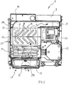
- Figure 2 shows a plane view of a first embodiment of a basement for a laundry dryer according to the invention
- Figure 3 shows a cross sectional view taken along line III-III in Figure 2 ;
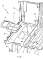
- Figure 4 shows a perspective view of a front part of basement shown in Figure 2 with a disassembled fluff filter
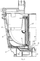
- Figure 5 shows a side cross sectional view taken along line V-V in Figure 2 ;
- Figure 6 shows a perspective cross sectional view taken along line V-V in Figure 2 ;
- Figure 7 shows an enlarged view of a part of Figure 2 with evidenced areas for supporting a refrigerant fluid evaporating unit and a refrigerant fluid condensing unit;
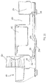
- Figure 8 shows a rear perspective view of a portion of laundry dryer illustrated in Figure 1 ;
- Figure 9 shows a plane view second embodiment of a basement for a laundry dryer according to the invention.
- Figure 10 shows a perspective view of a condensate reservoir of basement shown in Figure 9 ;
- Figure 11 shows a sectional view taken along line XI-XI of Figure 9 ;
- Figure 12 shows a bottom perspective view of the second embodiment of a basement.
- Figure 13 shows a partial sectional view taken along line XIII-XIII of Figure 9 ;
- a laundry dryer according to the invention comprises a casing 1 formed by a first couple of upright side walls 2A, 2B arranged on a front and rear side of the treating machine and by a second couple of upright side wall 2C, 2D arranged on lateral sides of such machine.
- An upper wall portion 3 and a bottom wall portion 4 close the ends of the box-like structure formed by the upright side walls 2A, 2B, 2C, 2D, joined together.
- a laundry container comprising a drum (not shown) rotatably mounted within the casing 1. Further operational devices, such as heat exchanging devices, fluid conduits, fluid pumping devices and so on, for carrying out a drying treatment on laundry are provided within the casing 1.
- An extractable moisture tank in the form of a drawer 6 is slidably arranged on the top of the casing 1, for being periodically emptied by a user in case the laundry dryer cannot be connected to a waste water net through a pipe.
- a user control interface 7 is arranged on the top of the casing 1 near the drawer 6 for input of laundry drying programs and displaying machine working conditions.
- a basement 8 On a bottom inner portion of the casing 1 a basement 8, 108 is provided as supporting structure for operational devices of drying machine.
- FIG 2 it is disclosed a first embodiment of a basement 8 suitable for being mounted on a heat pump type laundry drying machine.
- Basement 8 comprises a fan seat portion 9 for partly receiving a fan (not shown) that receives drying air, i.e. air circulating within a drying air circuit that fluidly connects a laundry container with air dehumidifying and air heating devices, from a conduit 10 collecting drying air after it is passed through said dehumidifying and heating devices.
- An electric motor seat 11 is arranged between the fan seat 9 and a refrigerant fluid compressor seat 12 such that an electric motor (not shown) may be accommodated on seat 11 and operatively connected to a fan and a refrigerant fluid compressor for powering them through a single shaft line.
- a refrigerant fluid compressor (not shown) is received on its seat 12 and forms part of a heat pump system which is further provided with a refrigerant fluid evaporating unit and a refrigerant fluid condensing unit for respectively dehumidifying and heating drying air passing therethrough.
- a refrigerant fluid evaporating unit and a refrigerant fluid condensing unit for respectively dehumidifying and heating drying air passing therethrough.
- Such evaporating unit and condensing unit may be accommodated on supporting surfaces 13, 14 formed onto basement 8.
- the refrigerant fluid condensing unit supporting surface 14 faces conduit 10 such that drying air heated by said condensing unit may be cyclically directed towards a fan inlet and then supplied to a laundry container.
- a surface 15 is provided in a basement region 17 upstream of said refrigerant fluid evaporating unit supporting surface 13 considering the drying air flow direction schematically indicated by arrows A in Figure 2 .
- Surface 15 is placed at the bottom of a chamber 16 ( Figure 3 ) and it is slightly sloping towards the refrigerant fluid evaporating unit.
- Chamber 16 receives drying air coming out from a laundry container laying over the basement 8 and then directs such air towards the refrigerant fluid evaporating unit for removing moisture therefrom by a condensing operation. Inside chamber 16 drying air changes its flow direction from a substantially vertical plane to a substantially horizontal plane before reaching the refrigerant fluid evaporating unit.
- the basement region 17 is, preferably, provided with a fluff filter 18 extending in a transverse direction relative to the drying air flow schematically indicated by arrow A in Figure 3 .
- Periodical cleaning of fluff filter 18 may be performed manually by removing filter 18 after having accessed chamber 16 through an opening 32 ( Figure 4 ) covered by a hinged door 20.
- surface 15 faces the evaporating unit of the heat pump system, i.e. a heat exchanger capable of condensing moisture contained in drying air, and considering that chamber 16 receives drying air after it has just left the laundry container, i.e. air highly enriched in moisture, surface 15 is arranged to drain moisture that condenses before entering the evaporating unit. A portion of a condensate draining path 21, 29B, 30B is therefore provided on surface 15 of basement region 17, i.e. in a front portion thereof. As mentioned above surface 15 is slightly sloping towards the refrigerant fluid evaporating unit, therefore condensate may flow towards path 21 sliding on surface 15 under gravity force effect.
- Walls 35 protrude from surface 13 to form a condensate collecting portion 36 that, when filled with condensate, generates a liquid trap preventing drying air entering chamber 16 to by-pass filter 18 escaping underneath the latter. In this way drying air rich in fluff is not passed towards the evaporating unit without being filtered through filter 18. Since drying air within chamber 16 has not yet passed through fluff filter 18, moisture condensed in that basement region 17 may have a relatively large amount of fluff impurities dispersed therein, for this reason a filter 22 is preferably provided onto the surface 15. In this way, condensate is filtered by filter 22 before entering the draining path 21. In order to allow periodical cleaning of filter 22, the later is, preferably, associated to a removable support 23 mountable on surface 15 by arranging it on a region 29B formed on such surface 15 as shown in Figure 4 and as it will be further described below.
- condensate draining path 21 that is preferably made integral with basement 8, extends from a front to a rear side of basement 8 along an edge region 25 thereof, and preferably in a direction which is substantially parallel to a drying air flow direction schematically indicated by arrows "A" in Figure 2 .
- condensate draining path 21 is configured and arranged not only to collect condensate dropped from the refrigerant fluid evaporating unit and that formed within chamber 16 as described above, but also condensate that may incidentally drop from the refrigerant fluid condensing unit.
- condensate draining path 21 is in fluid communication with the evaporating unit supporting surface 13 and with the condensing unit supporting surface 14 thereby avoiding undesired condensate accumulation on operational devices of laundry machine.
- condensate draining path 21 runs onto a basement surface portion 25 that supports neither the refrigerant evaporating unit nor the refrigerant condensing unit whose resting areas 40, 41 have been indicated in Figure 7 with a couple of rectangular hatches over supporting surfaces 13, 14, respectively.
- condensate draining path 21 it may extend only pipes bent portions for circulating a refrigerant inside said evaporating and condensing units, however, such pipes bent portions lays on higher planes relative to path 21 surface and therefore they do not touch the latter that remains free from obstructions and let the condensate to be drained towards reservoir 24.
- condensing draining path 21 preferably surrounds supporting surfaces 13, 14 without passing through them.
- condensate draining path 21 extends along a basement portion 25, which is free from evaporating and condensing units that therefore do not rest on that portion of the basement 8
- Each of said supporting surfaces 13 and 14 comprises at least one condensate guide 26 that extends transversally relative to condensate draining path 21 and has one or more walls 27, preferably sloping walls, integrally formed with basement 8 that extend transversally with respect to the extending direction of condensate draining path 21 and slope towards the latter such that condensate, under gravity force, flows to path 21.
- Further conveyors 28 configured and arranged for directing condensate towards sloping walls 27 are provided onto supporting surfaces 13 and 14, and such conveyors 28 may serve as resting surfaces for refrigerant fluid condensing and evaporating units.
- FIG. 5 shows a side cross sectional view of basement 8 taken along line V-V in Figure 2 .
- condensate draining path 21 slopes from the front part of basement (right side in Figure 5 ) to the rear part thereof (left side in Figure 5 ).
- supporting surfaces 13 and 14 are placed on a level "H" that is higher than levels "h” of condensate path 21 relative to the resting surface of basement 8 on a floor and form an angle with the path 21 extension surface.
- the basement surface portion 25 shown in Figures 2 , 6 and 7 extends on a lower level compared to supporting surfaces 13, 14. In this way, under gravity force, condensate can first flow from supporting surfaces 13, 14 into path 21 and then towards a reservoir 24.
- reservoir 24 is advantageously placed in the rear part of basement 8 in proximity of, but without being covered by, cabinet rear wall 2B, i.e. the wall opposite to cabinet wall 2A provided with a laundry loading opening closed by a hinged door 5. Furthermore, reservoir 24 is protected by a cover 42 associated to the cabinet rear wall 2B through a screw or the like. In this way, reservoir 24 may be easily accessible from the outside rear part of machine casing 1 by removing cover 42 and without the need to disassemble the whole rear side upright cabinet wall 2B. Further advantageously, reservoir 24 may be integrally molded with basement 8.
- Condensate received within reservoir 24 is pumped up by a pumping device 43 to an extractable moisture tank in the form of a drawer 6 ( Figure 1 ) placed on a front upper portion of the cabinet 1 for periodical emptying operation.
- a pumping device 43 By accessing reservoir 24 it is possible to reach pumping device 43 and a level sensor 44 that measures level of condensate within reservoir 24 to switch pumping device on only when condensate reaches a predetermined level within reservoir 24, maintenance operations can therefore be simplified.
- condensate air path 21 extends at least partly within drying air circuit while reservoir 24 is placed outside such circuit, i.e. it is separated from drying circuit. Therefore, in order to prevent drying air drained together with condensate along path 21 from reaching and entering reservoir 24, one or more condensate retaining regions 29A, 29B are provided in the condensate draining path 21 and/or on reservoir 24.
- the aim of said retaining regions 29A, 29B is to create a liquid barrier or trap to air that may accidentally be drained, i.e. dispersed through path 21.
- a siphon-shaped surface 30A that may have an outlet opening 36A placed either upstream of a passage 31 leading condensate from path 21 to reservoir 24 as depicted in Figure 6 , or forming itself the opening 31, i.e. coinciding with opening 31 such that said siphon-shaped surface 30A has an outlet section within reservoir 24.
- the outlet opening 36A can be provided downstream of opening 31
- condensate draining path 21 exists in the basement region 17 upstream of said refrigerant fluid evaporating unit supporting surface 13, it is preferred that a further condensate retaining region 29B ( Figures 2-4 and 6 ) is provided onto surface 15 placed at the bottom of chamber 16.
- region 29B advantageously in the form of a siphon-shaped surface 30B, may provide a seat for the condensate filter 22 and, preferably, may removably receive the support 23 of filter 22.
- Either of condensate retaining regions 29A, 29B may be integrally formed onto basement 8 as part of the condensate draining path 21.
- a further way to provide a liquid trap to drying air may be that of keeping opening 31 under a water head. This may be achieved by increasing the minimum water level inside the reservoir 24 on which pumping device 43 is activated for pumping condensate up to the extractable moisture tank in the form of a drawer 6. A water level increase can be obtained, in principle, by moving pumping device 43 and the condensate level sensor 44 higher relative to the resting surface of basement 8 on a floor.
- FIG. 9 it is disclosed a second embodiment of a basement 108 for a condenser type laundry dryer according to the invention.
- Such basement 108 comprises a first fan seat portion 109 for partly receiving a fan 145 (schematically shown in Figure 11 ) that moves drying air, i.e. air circulating within a drying air circuit that fluidly connects a laundry container with air dehumidifying and air heating devices.
- a second fan seat portion 133 partly receives a further fan for pumping ambient air towards an air-air condensing unit (not shown), laying over a basement supporting surface 114, as indicated by arrow "B" in Figures 9 .
- An electric motor seat 111 is arranged between the first and the second fan seats 109, 133 for powering them through a single shaft line.
- a condensing unit in the form of an air-air heat exchanger receives drying air in a direction schematically indicated by arrow "A" in Figure 9 , while cooling air is supplied along direction "B". In this way moisture contained in drying air is condensed and drops onto the condensing unit basement supporting surface 114. Said surface 114 forms a condensate guide 126 sloping towards the rear cabinet wall 2B thereby directing condensate in a reservoir 124. Similarly to the arrangement described above with reference to Figure 8 in connection with the first embodiment of the present invention, such reservoir 124 is placed in the rear part of basement 108 in proximity of, but without being covered by, cabinet rear wall 2B, i.e.
- reservoir 124 may be easily accessible from the outside rear part of machine casing 1 by removing only a cover attached thereon and without the need to disassemble the whole rear side upright cabinet wall 2B. Further advantageously, reservoir 124 may be integrally molded with basement 108. Still similarly to the arrangement described above with reference to Figure 8 , condensate collected within reservoir 124 is then pumped up by a pumping device to an extractable moisture tank in the form of a drawer 6 placed on a front upper portion of the cabinet 1 for periodical emptying operation.
- Condensing unit supporting surface 114 forms a part of a condensate draining path 121 extending in parallel with drying air flow and preferably made as integral part of basement 108.
- a further part of said path 121 extends transversally to the drying air flow in an edge region 125 of basement 108 and surrounds the supporting surface 114 for receiving condensate poured by the condensate guide 126 to lead it to reservoir 124.
- condensate draining path 121 extends at least partly within drying air circuit while reservoir 124 is placed outside such circuit, i.e. it is separated from drying circuit. Therefore, in order to prevent drying air drained together with condensate along path 121 from reaching and entering reservoir 124, a condensate retaining region 129A is provided in the condensate draining path 121 in proximity of reservoir 124, preferably as an integral part of basement 108. As already described with reference to the first embodiment of basement 8, the aim of said retaining region 129A is to create a liquid barrier or trap to air that may accidentally be drained, i.e. dispersed through path 121.
- siphon-shaped surface 130A may have an outlet opening which coincides with passage 131 to lead condensate from path 121 to reservoir 124, as shown in Figures 9 , 10 and 13 , or, as an alternative, such siphon-shaped surface 130A may have an outlet opening provided upstream of passage 131, i.e. in proximity thereof.
- outlet opening can be provided downstream of opening 131.
- FIG 13 shows how a condensate level "CL" within reservoir 124, being higher that the upper edge of passage 131, forms a liquid trap for preventing drying air dispersing along path 121 from entering reservoir 124.
- a further passage 147 which puts in fluid communication reservoir 124 with a conveyor portion 146 provided for receiving drying air flow "A" exiting a condensing unit (not shown) and deviating such air flow from a substantially horizontal plane to a substantially vertical plane so as to direct air within a laundry container. Since conveyor portion 146 may be a region subject where moisture still remaining within drying air may condensate, it is advantageous to fluidly connect this portion 146 with reservoir 124. Similarly to what has been described above with reference to passage 131, condensate level "CL" within reservoir 124 forms a liquid trap for preventing drying air circulating in the conveyor 146 from entering reservoir 124.
- basement 108 may be provided with a through bore 134 that is in fluid communication with reservoir 124 by means of a hose 137 that is placed on a opposite side of basement 108 relative to condensing draining path 121 and it is fluidly connected to reservoir 124 through a connector 138.
- Through bore 134 and the hose 137 connected thereto serves to drain moisture that may condense from drying air within the fan seat 109.
- a further condensate retaining region 129B may be formed in the hose 137 by simply bending the latter in a substantially U-shaped configuration thereby conferring to said region 129B a preferred siphon-shape surface 130B.
- a surface 115 is provided in a basement region 117 upstream of said condensing unit supporting surface 114 considering the drying air flow direction schematically indicated by arrows A in Figures 9 .
- Surface 115 is placed at the bottom of a chamber 116 of the basement region 117 that receives drying air coming out along a substantially vertical plane from a laundry container laying over the basement 8 and then directs such air towards the condensing unit for removing moisture therefrom by a condensing process along a substantially horizontal plane as indicated by arrow "A" in Figure 9 .
- the basement region 17 is preferably provided with a fluff filter extending in a transverse direction relative to the drying air flow schematically indicated by arrow A. Periodical cleaning of fluff filter may be performed manually by removing such filter after having accessed said chamber through an opening covered by a hinged door, similarly to what has been described above with reference to the first embodiment of basement 8.
- surface 115 faces the condensing unit, i.e. a heat exchanger capable of condensing moisture contained in drying air, and considering that chamber extending over surface 115 receives drying air after it has just left the laundry container, i.e. air highly enriched in moisture, surface 115 is arranged to drain moisture that condenses before entering the condensing unit. Therefore, a portion of a condensate draining path 121 may be provided on surface 115 of basement region 117, i.e. in a front portion thereof.
- a laundry dryer according to the invention allows to collect moisture that may incidentally condense onto regions of the drying air circuit where temperature is favorable and to efficiently drain it towards a reservoir. In this way condensate formed on undesired regions of a drying air circuit does not represent a source of possible performance reduction for operational components of a laundry dryer.
- a laundry dryer according to the invention has an efficient and reliable condensed moisture draining circuit interposing one or more physical, i.e. fluid, barrier to accidental passage of drying air from a drying air circuit to a reservoir where condensed water is collected.
- fluff incidentally flushed away by condensing moisture from surfaces onto which it may be accumulated is prevented from reaching a reservoir where condensate is collected thereby avoiding damages to a pump provided for pumping condensate from said reservoir to a main water container.
- the present invention can be applied to all machine suitable to carry out a drying treatment on laundry, i.e. it can be applied on a heat pump type laundry dryer, a condenser type laundry dryer or a washing-drying machine, that is a machine adapted to both washing and drying laundry.
Claims (12)
- Wäschetrockner, der ein Gehäuse (1) umfasst, in dem ein Trocknungsluftkreislauf, ein Wäschebehälter, eine Trocknungsluftfeuchtigkeits-Entfernungseinheit und weitere Betriebsvorrichtungen zur Durchführung einer Trocknungsbehandlung an der Wäsche untergebracht sind, wobei der Trockner ferner einen Sockel (8) mit einem Kondensatableitungsweg (21) zur Beförderung der von der Trocknungsluft kondensierten Feuchtigkeit in ein Reservoir (24) umfasst, wobei sich wenigstens ein Teil des Kondensatableitungswegs (21) über einen Sockelbereich (17) erstreckt, wo die aus dem Wäschebehälter austretende Trocknungsluft entlang strömt, bevor sie in die Trocknungsluftfeuchtigkeits-Entfernungseinheit eindringt, dadurch gekennzeichnet, dass ein Luftfilter (18), der sich im wesentlichen in einer Querrichtung im Verhältnis zum Trocknungsluftstrom erstreckt, im Sockelbereich (17, 117) vorgesehen ist und der Kondensatableitungsweg (21, 121) wenigstens einen Kondensatrückhaltebereich (29A, 29B; 129A, 129B) umfasst, um eine Flüssigkeitsfalle zu bilden, um die Trocknungsluft daran zu hindern, den Luftfilter (18) zu umgehen.
- Wäschetrockner gemäß Anspruch 1 oder 2, wobei der wenigstens eine Kondensatrückhaltebereich (29A, 29B; 129A, 129B) eine Siphon-förmige Oberfläche (30A, 30B; 130A, 130B) umfasst.
- Wäschetrockner gemäß einem der vorangehenden Ansprüche, wobei sich der Kondensatableitungsweg (21, 121) von einer Vorder- zu einer Rückseite desselben wenigstens teilweise in einem Randbereich (25, 125) des Sockels (8, 108) erstreckt.
- Wäschetrockner gemäß einem der vorangehenden Ansprüche, wobei sich wenigstens ein Teil des Kondensatableitungswegs (21, 121) zum Sockel (8, 108) in eine Richtung erstreckt, die im wesentlichen parallel zu einer Trocknungsluftströmungsrichtung (A) ist.
- Wäschetrockner gemäß einem der vorangehenden Ansprüche, wobei das Reservoir (24, 124) in der Nähe einer ersten Schrankrückwand (2B) angeordnet ist, die gegenüber einer zweiten Schrankvorderwand (2A) angeordnet ist, an der eine Wäschebeladeöffnung ausgebildet ist.
- Wäschetrockner gemäß einem der vorangehenden Ansprüche, wobei der Wärmetauscher über einer Unterstützungsfläche (14, 114) liegt, die eine oder mehrere Kondensatführungen (26, 126) zum Weiterleiten des Kondensats zum Kondensatableitungsweg (21, 121) umfasst.
- Wäschetrockner gemäß Anspruch 6, der einen weiteren Wärmetauscher zum Erhitzen des Trocknungsluftstroms umfasst, der in Serie mit dem feuchtigkeitskondensierenden Wärmetauscher angeordnet ist, wobei beide Wärmetauscher über einer Unterstützungsfläche (13, 14) liegen, die wenigstens teilweise vom Kondensatableitungsweg (21) umgeben ist.
- Wäschetrockner gemäß Anspruch 7, wobei Kondensatführungen (26) eine oder mehrere Wände (27) umfassen, die sich mit Bezug auf die Richtung, entlang der sich der Kondensatableitungsweg (21) erstreckt, quer erstrecken und zum Pfad (21) hin geneigt sind.
- Wäschetrockner gemäß einem der vorangehenden Ansprüche, wobei der Sockelbereich (17) einen Filter (22) umfasst, durch den Kondensat zur Entfernung von Verunreinigungen geführt wird.
- Wäschetrockner gemäß einem der vorangehenden Ansprüche, wobei der Kondensatableitungsweg (21) wenigstens einen mit einem Filter (22) versehenen Kondensatrückhaltebereich (29B) umfasst.
- Wäschetrockner gemäß einem der Ansprüche 1 bis 6, wobei der Sockel (108) einen Luftpumpenvorrichtungs-Haltesitz (109) mit einer durchgehenden Bohrung (134) in Fluidkommunikation mit dem Reservoir (124) umfasst.
- Wäschetrockner gemäß einem der vorangehenden Ansprüche, wobei sich der Abschnitt des Kondensatableitungswegs (21, 121) in einem Sockelbereich (17, 117) erstreckt, wo die aus dem Wäschebehälter austretende Trocknungsluft ihre Strömungsrichtung von einer im wesentlichen vertikalen Ebene in eine im wesentlichen horizontale Ebene ändert, bevor sie in die Trocknungsluftfeuchtigkeits-Entfernungseinheit eintritt.
Priority Applications (7)
| Application Number | Priority Date | Filing Date | Title |
|---|---|---|---|
| EP10192930.5A EP2458073B1 (de) | 2010-11-29 | 2010-11-29 | Wäschetrockner |
| CN201180057163.8A CN103370466B (zh) | 2010-11-29 | 2011-11-24 | 衣物干燥机 |
| AU2011335189A AU2011335189B2 (en) | 2010-11-29 | 2011-11-24 | Laundry dryer |
| PCT/EP2011/070920 WO2012072482A2 (en) | 2010-11-29 | 2011-11-24 | Laundry dryer |
| BR112013013217A BR112013013217A2 (pt) | 2010-11-29 | 2011-11-24 | secadora de roupas |
| US13/988,603 US20130312274A1 (en) | 2010-11-29 | 2011-11-24 | Laundry dryer |
| RU2013129931/12A RU2013129931A (ru) | 2010-11-29 | 2011-11-24 | Сушильная машина для белья |
Applications Claiming Priority (1)
| Application Number | Priority Date | Filing Date | Title |
|---|---|---|---|
| EP10192930.5A EP2458073B1 (de) | 2010-11-29 | 2010-11-29 | Wäschetrockner |
Publications (2)
| Publication Number | Publication Date |
|---|---|
| EP2458073A1 EP2458073A1 (de) | 2012-05-30 |
| EP2458073B1 true EP2458073B1 (de) | 2013-11-20 |
Family
ID=43919783
Family Applications (1)
| Application Number | Title | Priority Date | Filing Date |
|---|---|---|---|
| EP10192930.5A Active EP2458073B1 (de) | 2010-11-29 | 2010-11-29 | Wäschetrockner |
Country Status (7)
| Country | Link |
|---|---|
| US (1) | US20130312274A1 (de) |
| EP (1) | EP2458073B1 (de) |
| CN (1) | CN103370466B (de) |
| AU (1) | AU2011335189B2 (de) |
| BR (1) | BR112013013217A2 (de) |
| RU (1) | RU2013129931A (de) |
| WO (1) | WO2012072482A2 (de) |
Families Citing this family (9)
| Publication number | Priority date | Publication date | Assignee | Title |
|---|---|---|---|---|
| PL2843123T3 (pl) * | 2013-08-30 | 2022-10-31 | Electrolux Appliances Aktiebolag | Urządzenie do suszenia prania z pomocniczym filtrem kłaczków |
| EP3023531B1 (de) * | 2014-11-19 | 2018-06-06 | Samsung Electronics Co., Ltd | Wäschetrockner |
| JP6616590B2 (ja) * | 2015-05-19 | 2019-12-04 | 三星電子株式会社 | 乾燥機 |
| KR102435202B1 (ko) * | 2015-09-30 | 2022-08-24 | 삼성전자주식회사 | 제습기 |
| CN106367932A (zh) * | 2016-09-30 | 2017-02-01 | 无锡小天鹅股份有限公司 | 干衣机 |
| US10480117B2 (en) * | 2017-02-27 | 2019-11-19 | Whirlpool Corporation | Self cleaning sump cover |
| AU2019267033B2 (en) * | 2018-05-08 | 2023-03-30 | Lg Electronics Inc. | Clothes treatment apparatus and control method therefor |
| CN114075770B (zh) * | 2020-08-21 | 2022-12-20 | 无锡小天鹅电器有限公司 | 用于干衣机的风道壳和干衣机 |
| CN114075771B (zh) * | 2020-08-21 | 2023-02-28 | 无锡小天鹅电器有限公司 | 用于干衣机的风道壳和干衣机 |
Family Cites Families (6)
| Publication number | Priority date | Publication date | Assignee | Title |
|---|---|---|---|---|
| DE10002742C1 (de) * | 2000-01-22 | 2001-06-28 | Whirlpool Co | Wärmepumpen-Wäschetrockner |
| US6868689B1 (en) * | 2001-04-20 | 2005-03-22 | Buffalo Air Handling Company | Condensate drain pan |
| DE20304521U1 (de) * | 2003-03-20 | 2003-05-22 | Miele & Cie | Kondensationswäschetrockner |
| KR101021778B1 (ko) * | 2003-12-26 | 2011-03-15 | 엘지전자 주식회사 | 건조기의 컨덴서 하단부 배수유로 구조 |
| KR101180532B1 (ko) * | 2005-05-23 | 2012-09-06 | 엘지전자 주식회사 | 응축수 저장 구조가 구비된 의류 건조기 |
| CN101078172A (zh) * | 2006-05-23 | 2007-11-28 | 南京乐金熊猫电器有限公司 | 配备冷凝水储存结构的干衣机 |
-
2010
- 2010-11-29 EP EP10192930.5A patent/EP2458073B1/de active Active
-
2011
- 2011-11-24 RU RU2013129931/12A patent/RU2013129931A/ru not_active Application Discontinuation
- 2011-11-24 US US13/988,603 patent/US20130312274A1/en not_active Abandoned
- 2011-11-24 BR BR112013013217A patent/BR112013013217A2/pt not_active IP Right Cessation
- 2011-11-24 AU AU2011335189A patent/AU2011335189B2/en not_active Ceased
- 2011-11-24 WO PCT/EP2011/070920 patent/WO2012072482A2/en active Application Filing
- 2011-11-24 CN CN201180057163.8A patent/CN103370466B/zh not_active Expired - Fee Related
Also Published As
| Publication number | Publication date |
|---|---|
| WO2012072482A3 (en) | 2012-07-26 |
| AU2011335189B2 (en) | 2015-01-29 |
| CN103370466B (zh) | 2015-11-25 |
| EP2458073A1 (de) | 2012-05-30 |
| AU2011335189A1 (en) | 2013-04-11 |
| RU2013129931A (ru) | 2015-01-10 |
| WO2012072482A2 (en) | 2012-06-07 |
| CN103370466A (zh) | 2013-10-23 |
| US20130312274A1 (en) | 2013-11-28 |
| BR112013013217A2 (pt) | 2016-09-06 |
Similar Documents
| Publication | Publication Date | Title |
|---|---|---|
| AU2011335184B2 (en) | Laundry dryer | |
| EP2458073B1 (de) | Wäschetrockner | |
| EP2458074A1 (de) | Wärmepumpenwäschetrockner | |
| EP3090093B1 (de) | Wäschebehandlungsvorrichtung mit flusensiebwaschanlage | |
| EP1936022A1 (de) | Wäschetrockner | |
| EP3090094B1 (de) | Wäschebehandlungsvorrichtung mit flusensiebwaschanlage | |
| WO2006097901A2 (en) | A washer/dryer | |
| RU2411317C1 (ru) | Устройство для кондиционирования воздуха | |
| EP3237674B1 (de) | Wäschetrocknungsvorrichtung mit pumpe zum ablassen von flüssigkeit | |
| EP3234254B1 (de) | Wäschebehandlungsvorrichtung mit wärmetauscher und kondensatsammler | |
| RU2411318C1 (ru) | Устройство для кондиционирования воздуха (варианты) | |
| EP2799612B1 (de) | Wärmepumpenvorrichtung zur Wäschebehandlung | |
| EP2719819A1 (de) | Wärmepumpenwäschetrockner | |
| EP2042646A1 (de) | Haushaltswäschetrockner | |
| EP3029194B1 (de) | Wäschetrockner | |
| CN112912560A (zh) | 洗干一体机 | |
| EP3467187B1 (de) | Zur verwendung in einer maschine zum trocknen von wäsche konfigurierter filter und mit solch einem filter ausgestattete maschine zum trocknen von wäsche | |
| EP3124683B1 (de) | Wäschetrockner | |
| RU2415217C1 (ru) | Устройство для кондиционирования воздуха | |
| CN112912561A (zh) | 洗干一体机 | |
| EP4029980A1 (de) | Wäschetrockner mit einem dampferzeuger |
Legal Events
| Date | Code | Title | Description |
|---|---|---|---|
| PUAI | Public reference made under article 153(3) epc to a published international application that has entered the european phase |
Free format text: ORIGINAL CODE: 0009012 |
|
| AK | Designated contracting states |
Kind code of ref document: A1 Designated state(s): AL AT BE BG CH CY CZ DE DK EE ES FI FR GB GR HR HU IE IS IT LI LT LU LV MC MK MT NL NO PL PT RO RS SE SI SK SM TR |
|
| AX | Request for extension of the european patent |
Extension state: BA ME |
|
| 17P | Request for examination filed |
Effective date: 20121130 |
|
| GRAP | Despatch of communication of intention to grant a patent |
Free format text: ORIGINAL CODE: EPIDOSNIGR1 |
|
| INTG | Intention to grant announced |
Effective date: 20130610 |
|
| GRAS | Grant fee paid |
Free format text: ORIGINAL CODE: EPIDOSNIGR3 |
|
| GRAA | (expected) grant |
Free format text: ORIGINAL CODE: 0009210 |
|
| AK | Designated contracting states |
Kind code of ref document: B1 Designated state(s): AL AT BE BG CH CY CZ DE DK EE ES FI FR GB GR HR HU IE IS IT LI LT LU LV MC MK MT NL NO PL PT RO RS SE SI SK SM TR |
|
| REG | Reference to a national code |
Ref country code: GB Ref legal event code: FG4D |
|
| REG | Reference to a national code |
Ref country code: CH Ref legal event code: EP |
|
| REG | Reference to a national code |
Ref country code: AT Ref legal event code: REF Ref document number: 641741 Country of ref document: AT Kind code of ref document: T Effective date: 20131215 |
|
| REG | Reference to a national code |
Ref country code: IE Ref legal event code: FG4D |
|
| REG | Reference to a national code |
Ref country code: DE Ref legal event code: R096 Ref document number: 602010011845 Country of ref document: DE Effective date: 20140116 |
|
| REG | Reference to a national code |
Ref country code: NL Ref legal event code: VDEP Effective date: 20131120 |
|
| REG | Reference to a national code |
Ref country code: AT Ref legal event code: MK05 Ref document number: 641741 Country of ref document: AT Kind code of ref document: T Effective date: 20131120 |
|
| REG | Reference to a national code |
Ref country code: LT Ref legal event code: MG4D |
|
| PG25 | Lapsed in a contracting state [announced via postgrant information from national office to epo] |
Ref country code: SE Free format text: LAPSE BECAUSE OF FAILURE TO SUBMIT A TRANSLATION OF THE DESCRIPTION OR TO PAY THE FEE WITHIN THE PRESCRIBED TIME-LIMIT Effective date: 20131120 Ref country code: IS Free format text: LAPSE BECAUSE OF FAILURE TO SUBMIT A TRANSLATION OF THE DESCRIPTION OR TO PAY THE FEE WITHIN THE PRESCRIBED TIME-LIMIT Effective date: 20140320 Ref country code: LT Free format text: LAPSE BECAUSE OF FAILURE TO SUBMIT A TRANSLATION OF THE DESCRIPTION OR TO PAY THE FEE WITHIN THE PRESCRIBED TIME-LIMIT Effective date: 20131120 Ref country code: NO Free format text: LAPSE BECAUSE OF FAILURE TO SUBMIT A TRANSLATION OF THE DESCRIPTION OR TO PAY THE FEE WITHIN THE PRESCRIBED TIME-LIMIT Effective date: 20140220 Ref country code: HR Free format text: LAPSE BECAUSE OF FAILURE TO SUBMIT A TRANSLATION OF THE DESCRIPTION OR TO PAY THE FEE WITHIN THE PRESCRIBED TIME-LIMIT Effective date: 20131120 Ref country code: FI Free format text: LAPSE BECAUSE OF FAILURE TO SUBMIT A TRANSLATION OF THE DESCRIPTION OR TO PAY THE FEE WITHIN THE PRESCRIBED TIME-LIMIT Effective date: 20131120 Ref country code: NL Free format text: LAPSE BECAUSE OF FAILURE TO SUBMIT A TRANSLATION OF THE DESCRIPTION OR TO PAY THE FEE WITHIN THE PRESCRIBED TIME-LIMIT Effective date: 20131120 |
|
| PG25 | Lapsed in a contracting state [announced via postgrant information from national office to epo] |
Ref country code: BE Free format text: LAPSE BECAUSE OF FAILURE TO SUBMIT A TRANSLATION OF THE DESCRIPTION OR TO PAY THE FEE WITHIN THE PRESCRIBED TIME-LIMIT Effective date: 20131120 Ref country code: ES Free format text: LAPSE BECAUSE OF FAILURE TO SUBMIT A TRANSLATION OF THE DESCRIPTION OR TO PAY THE FEE WITHIN THE PRESCRIBED TIME-LIMIT Effective date: 20131120 Ref country code: LV Free format text: LAPSE BECAUSE OF FAILURE TO SUBMIT A TRANSLATION OF THE DESCRIPTION OR TO PAY THE FEE WITHIN THE PRESCRIBED TIME-LIMIT Effective date: 20131120 Ref country code: RS Free format text: LAPSE BECAUSE OF FAILURE TO SUBMIT A TRANSLATION OF THE DESCRIPTION OR TO PAY THE FEE WITHIN THE PRESCRIBED TIME-LIMIT Effective date: 20131120 Ref country code: AT Free format text: LAPSE BECAUSE OF FAILURE TO SUBMIT A TRANSLATION OF THE DESCRIPTION OR TO PAY THE FEE WITHIN THE PRESCRIBED TIME-LIMIT Effective date: 20131120 |
|
| PG25 | Lapsed in a contracting state [announced via postgrant information from national office to epo] |
Ref country code: PT Free format text: LAPSE BECAUSE OF FAILURE TO SUBMIT A TRANSLATION OF THE DESCRIPTION OR TO PAY THE FEE WITHIN THE PRESCRIBED TIME-LIMIT Effective date: 20140320 |
|
| PG25 | Lapsed in a contracting state [announced via postgrant information from national office to epo] |
Ref country code: EE Free format text: LAPSE BECAUSE OF FAILURE TO SUBMIT A TRANSLATION OF THE DESCRIPTION OR TO PAY THE FEE WITHIN THE PRESCRIBED TIME-LIMIT Effective date: 20131120 |
|
| REG | Reference to a national code |
Ref country code: DE Ref legal event code: R097 Ref document number: 602010011845 Country of ref document: DE |
|
| REG | Reference to a national code |
Ref country code: IE Ref legal event code: MM4A |
|
| PG25 | Lapsed in a contracting state [announced via postgrant information from national office to epo] |
Ref country code: PL Free format text: LAPSE BECAUSE OF FAILURE TO SUBMIT A TRANSLATION OF THE DESCRIPTION OR TO PAY THE FEE WITHIN THE PRESCRIBED TIME-LIMIT Effective date: 20131120 Ref country code: RO Free format text: LAPSE BECAUSE OF FAILURE TO SUBMIT A TRANSLATION OF THE DESCRIPTION OR TO PAY THE FEE WITHIN THE PRESCRIBED TIME-LIMIT Effective date: 20131120 Ref country code: CZ Free format text: LAPSE BECAUSE OF FAILURE TO SUBMIT A TRANSLATION OF THE DESCRIPTION OR TO PAY THE FEE WITHIN THE PRESCRIBED TIME-LIMIT Effective date: 20131120 Ref country code: SK Free format text: LAPSE BECAUSE OF FAILURE TO SUBMIT A TRANSLATION OF THE DESCRIPTION OR TO PAY THE FEE WITHIN THE PRESCRIBED TIME-LIMIT Effective date: 20131120 |
|
| PLBE | No opposition filed within time limit |
Free format text: ORIGINAL CODE: 0009261 |
|
| STAA | Information on the status of an ep patent application or granted ep patent |
Free format text: STATUS: NO OPPOSITION FILED WITHIN TIME LIMIT |
|
| PG25 | Lapsed in a contracting state [announced via postgrant information from national office to epo] |
Ref country code: DK Free format text: LAPSE BECAUSE OF FAILURE TO SUBMIT A TRANSLATION OF THE DESCRIPTION OR TO PAY THE FEE WITHIN THE PRESCRIBED TIME-LIMIT Effective date: 20131120 |
|
| 26N | No opposition filed |
Effective date: 20140821 |
|
| PG25 | Lapsed in a contracting state [announced via postgrant information from national office to epo] |
Ref country code: IE Free format text: LAPSE BECAUSE OF NON-PAYMENT OF DUE FEES Effective date: 20131129 |
|
| REG | Reference to a national code |
Ref country code: DE Ref legal event code: R097 Ref document number: 602010011845 Country of ref document: DE Effective date: 20140821 |
|
| PG25 | Lapsed in a contracting state [announced via postgrant information from national office to epo] |
Ref country code: SI Free format text: LAPSE BECAUSE OF FAILURE TO SUBMIT A TRANSLATION OF THE DESCRIPTION OR TO PAY THE FEE WITHIN THE PRESCRIBED TIME-LIMIT Effective date: 20131120 |
|
| PG25 | Lapsed in a contracting state [announced via postgrant information from national office to epo] |
Ref country code: MC Free format text: LAPSE BECAUSE OF FAILURE TO SUBMIT A TRANSLATION OF THE DESCRIPTION OR TO PAY THE FEE WITHIN THE PRESCRIBED TIME-LIMIT Effective date: 20131120 |
|
| PG25 | Lapsed in a contracting state [announced via postgrant information from national office to epo] |
Ref country code: SM Free format text: LAPSE BECAUSE OF FAILURE TO SUBMIT A TRANSLATION OF THE DESCRIPTION OR TO PAY THE FEE WITHIN THE PRESCRIBED TIME-LIMIT Effective date: 20131120 |
|
| PG25 | Lapsed in a contracting state [announced via postgrant information from national office to epo] |
Ref country code: TR Free format text: LAPSE BECAUSE OF FAILURE TO SUBMIT A TRANSLATION OF THE DESCRIPTION OR TO PAY THE FEE WITHIN THE PRESCRIBED TIME-LIMIT Effective date: 20131120 Ref country code: CY Free format text: LAPSE BECAUSE OF FAILURE TO SUBMIT A TRANSLATION OF THE DESCRIPTION OR TO PAY THE FEE WITHIN THE PRESCRIBED TIME-LIMIT Effective date: 20131120 |
|
| REG | Reference to a national code |
Ref country code: CH Ref legal event code: PL |
|
| PG25 | Lapsed in a contracting state [announced via postgrant information from national office to epo] |
Ref country code: MK Free format text: LAPSE BECAUSE OF FAILURE TO SUBMIT A TRANSLATION OF THE DESCRIPTION OR TO PAY THE FEE WITHIN THE PRESCRIBED TIME-LIMIT Effective date: 20131120 Ref country code: LI Free format text: LAPSE BECAUSE OF NON-PAYMENT OF DUE FEES Effective date: 20141130 Ref country code: BG Free format text: LAPSE BECAUSE OF FAILURE TO SUBMIT A TRANSLATION OF THE DESCRIPTION OR TO PAY THE FEE WITHIN THE PRESCRIBED TIME-LIMIT Effective date: 20131120 Ref country code: CH Free format text: LAPSE BECAUSE OF NON-PAYMENT OF DUE FEES Effective date: 20141130 Ref country code: HU Free format text: LAPSE BECAUSE OF FAILURE TO SUBMIT A TRANSLATION OF THE DESCRIPTION OR TO PAY THE FEE WITHIN THE PRESCRIBED TIME-LIMIT; INVALID AB INITIO Effective date: 20101129 Ref country code: LU Free format text: LAPSE BECAUSE OF NON-PAYMENT OF DUE FEES Effective date: 20131129 |
|
| PG25 | Lapsed in a contracting state [announced via postgrant information from national office to epo] |
Ref country code: GR Free format text: LAPSE BECAUSE OF NON-PAYMENT OF DUE FEES Effective date: 20131120 Ref country code: MT Free format text: LAPSE BECAUSE OF FAILURE TO SUBMIT A TRANSLATION OF THE DESCRIPTION OR TO PAY THE FEE WITHIN THE PRESCRIBED TIME-LIMIT Effective date: 20131120 |
|
| REG | Reference to a national code |
Ref country code: FR Ref legal event code: PLFP Year of fee payment: 6 |
|
| PGFP | Annual fee paid to national office [announced via postgrant information from national office to epo] |
Ref country code: GB Payment date: 20151118 Year of fee payment: 6 |
|
| PGFP | Annual fee paid to national office [announced via postgrant information from national office to epo] |
Ref country code: FR Payment date: 20151119 Year of fee payment: 6 |
|
| PG25 | Lapsed in a contracting state [announced via postgrant information from national office to epo] |
Ref country code: GR Free format text: LAPSE BECAUSE OF FAILURE TO SUBMIT A TRANSLATION OF THE DESCRIPTION OR TO PAY THE FEE WITHIN THE PRESCRIBED TIME-LIMIT Effective date: 20140221 |
|
| GBPC | Gb: european patent ceased through non-payment of renewal fee |
Effective date: 20161129 |
|
| REG | Reference to a national code |
Ref country code: FR Ref legal event code: ST Effective date: 20170731 |
|
| PG25 | Lapsed in a contracting state [announced via postgrant information from national office to epo] |
Ref country code: FR Free format text: LAPSE BECAUSE OF NON-PAYMENT OF DUE FEES Effective date: 20161130 |
|
| PG25 | Lapsed in a contracting state [announced via postgrant information from national office to epo] |
Ref country code: GB Free format text: LAPSE BECAUSE OF NON-PAYMENT OF DUE FEES Effective date: 20161129 |
|
| PG25 | Lapsed in a contracting state [announced via postgrant information from national office to epo] |
Ref country code: AL Free format text: LAPSE BECAUSE OF FAILURE TO SUBMIT A TRANSLATION OF THE DESCRIPTION OR TO PAY THE FEE WITHIN THE PRESCRIBED TIME-LIMIT Effective date: 20131120 |
|
| PGFP | Annual fee paid to national office [announced via postgrant information from national office to epo] |
Ref country code: IT Payment date: 20181126 Year of fee payment: 9 |
|
| PG25 | Lapsed in a contracting state [announced via postgrant information from national office to epo] |
Ref country code: IT Free format text: LAPSE BECAUSE OF NON-PAYMENT OF DUE FEES Effective date: 20191129 |
|
| P01 | Opt-out of the competence of the unified patent court (upc) registered |
Effective date: 20230625 |
|
| PGFP | Annual fee paid to national office [announced via postgrant information from national office to epo] |
Ref country code: DE Payment date: 20231127 Year of fee payment: 14 |