EP2458027A1 - Dimensionally stable durable thermal spray masking system - Google Patents
Dimensionally stable durable thermal spray masking system Download PDFInfo
- Publication number
- EP2458027A1 EP2458027A1 EP11191271A EP11191271A EP2458027A1 EP 2458027 A1 EP2458027 A1 EP 2458027A1 EP 11191271 A EP11191271 A EP 11191271A EP 11191271 A EP11191271 A EP 11191271A EP 2458027 A1 EP2458027 A1 EP 2458027A1
- Authority
- EP
- European Patent Office
- Prior art keywords
- masking system
- masking
- conduit
- base
- annular
- Prior art date
- Legal status (The legal status is an assumption and is not a legal conclusion. Google has not performed a legal analysis and makes no representation as to the accuracy of the status listed.)
- Withdrawn
Links
- 230000000873 masking effect Effects 0.000 title claims abstract description 55
- 239000007921 spray Substances 0.000 title description 9
- 230000000284 resting effect Effects 0.000 claims abstract description 3
- 239000011248 coating agent Substances 0.000 description 8
- 238000000576 coating method Methods 0.000 description 8
- 239000012530 fluid Substances 0.000 description 6
- 239000000463 material Substances 0.000 description 4
- 238000000034 method Methods 0.000 description 2
- 238000012986 modification Methods 0.000 description 2
- 230000004048 modification Effects 0.000 description 2
- 230000009286 beneficial effect Effects 0.000 description 1
- 239000000919 ceramic Substances 0.000 description 1
- 239000010960 cold rolled steel Substances 0.000 description 1
- 229910001026 inconel Inorganic materials 0.000 description 1
- 238000004519 manufacturing process Methods 0.000 description 1
- 239000002184 metal Substances 0.000 description 1
- 239000007769 metal material Substances 0.000 description 1
- 229920000642 polymer Polymers 0.000 description 1
- 125000006850 spacer group Chemical group 0.000 description 1
- 238000009718 spray deposition Methods 0.000 description 1
- 238000005507 spraying Methods 0.000 description 1
Images
Classifications
-
- C—CHEMISTRY; METALLURGY
- C23—COATING METALLIC MATERIAL; COATING MATERIAL WITH METALLIC MATERIAL; CHEMICAL SURFACE TREATMENT; DIFFUSION TREATMENT OF METALLIC MATERIAL; COATING BY VACUUM EVAPORATION, BY SPUTTERING, BY ION IMPLANTATION OR BY CHEMICAL VAPOUR DEPOSITION, IN GENERAL; INHIBITING CORROSION OF METALLIC MATERIAL OR INCRUSTATION IN GENERAL
- C23C—COATING METALLIC MATERIAL; COATING MATERIAL WITH METALLIC MATERIAL; SURFACE TREATMENT OF METALLIC MATERIAL BY DIFFUSION INTO THE SURFACE, BY CHEMICAL CONVERSION OR SUBSTITUTION; COATING BY VACUUM EVAPORATION, BY SPUTTERING, BY ION IMPLANTATION OR BY CHEMICAL VAPOUR DEPOSITION, IN GENERAL
- C23C4/00—Coating by spraying the coating material in the molten state, e.g. by flame, plasma or electric discharge
- C23C4/02—Pretreatment of the material to be coated, e.g. for coating on selected surface areas
-
- B—PERFORMING OPERATIONS; TRANSPORTING
- B05—SPRAYING OR ATOMISING IN GENERAL; APPLYING FLUENT MATERIALS TO SURFACES, IN GENERAL
- B05B—SPRAYING APPARATUS; ATOMISING APPARATUS; NOZZLES
- B05B12/00—Arrangements for controlling delivery; Arrangements for controlling the spray area
- B05B12/16—Arrangements for controlling delivery; Arrangements for controlling the spray area for controlling the spray area
- B05B12/18—Arrangements for controlling delivery; Arrangements for controlling the spray area for controlling the spray area using fluids, e.g. gas streams
-
- B—PERFORMING OPERATIONS; TRANSPORTING
- B05—SPRAYING OR ATOMISING IN GENERAL; APPLYING FLUENT MATERIALS TO SURFACES, IN GENERAL
- B05B—SPRAYING APPARATUS; ATOMISING APPARATUS; NOZZLES
- B05B12/00—Arrangements for controlling delivery; Arrangements for controlling the spray area
- B05B12/16—Arrangements for controlling delivery; Arrangements for controlling the spray area for controlling the spray area
- B05B12/20—Masking elements, i.e. elements defining uncoated areas on an object to be coated
-
- C—CHEMISTRY; METALLURGY
- C23—COATING METALLIC MATERIAL; COATING MATERIAL WITH METALLIC MATERIAL; CHEMICAL SURFACE TREATMENT; DIFFUSION TREATMENT OF METALLIC MATERIAL; COATING BY VACUUM EVAPORATION, BY SPUTTERING, BY ION IMPLANTATION OR BY CHEMICAL VAPOUR DEPOSITION, IN GENERAL; INHIBITING CORROSION OF METALLIC MATERIAL OR INCRUSTATION IN GENERAL
- C23C—COATING METALLIC MATERIAL; COATING MATERIAL WITH METALLIC MATERIAL; SURFACE TREATMENT OF METALLIC MATERIAL BY DIFFUSION INTO THE SURFACE, BY CHEMICAL CONVERSION OR SUBSTITUTION; COATING BY VACUUM EVAPORATION, BY SPUTTERING, BY ION IMPLANTATION OR BY CHEMICAL VAPOUR DEPOSITION, IN GENERAL
- C23C4/00—Coating by spraying the coating material in the molten state, e.g. by flame, plasma or electric discharge
- C23C4/01—Selective coating, e.g. pattern coating, without pre-treatment of the material to be coated
-
- F—MECHANICAL ENGINEERING; LIGHTING; HEATING; WEAPONS; BLASTING
- F05—INDEXING SCHEMES RELATING TO ENGINES OR PUMPS IN VARIOUS SUBCLASSES OF CLASSES F01-F04
- F05B—INDEXING SCHEME RELATING TO WIND, SPRING, WEIGHT, INERTIA OR LIKE MOTORS, TO MACHINES OR ENGINES FOR LIQUIDS COVERED BY SUBCLASSES F03B, F03D AND F03G
- F05B2230/00—Manufacture
- F05B2230/30—Manufacture with deposition of material
- F05B2230/31—Layer deposition
- F05B2230/312—Layer deposition by plasma spray
Definitions
- the present disclosure relates to a dimensionally stable durable thermal spray masking system for protecting a portion of a part such as a turbine engine component.
- Certain rotors and rotor spacers that receive ceramic thermal spray coatings have very tight spacing of the coating pocket to no-coat areas such as blades and surfaces that mate to adjacent parts. These no-coat areas are typically masked in order to protect them from plasma spray deposition.
- Conventional tape and polymer based maskants tend to burn off due to the high heat input from the spray process that is associated with achieving a microcracked structure of the coating.
- Durable metal based masking has been made from Inconel sheet stock and machined from thick sections. Due to the high heat input of the process, these masks may distort and may not maintain the tight tolerances necessary along the edges of the coat to no-coat regions.
- a masking system for protecting portions of a part to be coated which masking system broadly comprises a base, a conduit mounted on said base, said part to be coated being positioned over said conduit, and an annular plate positioned over said conduit and resting on a first portion of said part.
- the part may be a turbine engine component.
- a masking system for protecting portions of a turbine engine component being coated comprising a central conduit positioned on a base, an annular tube positioned on said base, a turbine engine component having a plurality of airfoils positioned over said central conduit, and means for reducing overspraying adhering to said airfoils.
- a system for masking a portion of a part, such as a turbine engine component, to be coated has durable metallic masking features that are free to expand and contract without distortion. These features are known as floating rings. These rings are relatively small and mostly, if not completely, coated with the part. The rings are not intended to provide full protection to the part; however, the rings do create the close tolerance edge feature which is needed. The rings work to hold tight tolerances because the rings come up to temperature during spray with the part while not being constrained by additional mask features that are not equally heated. The rings are easily replaceable since they are not fixed to their support structures.
- the system described herein provides masking which is pressurized with air to create a leakage flow along the gap between the masking and the coating area. This is to help counter the flow of overspray material that deflects under the mask and prevent it from adhering to portions of the part being coated, such as the airfoils of an integrally bladed rotor (IBR).
- IBR integrally bladed rotor
- the masking system 10 for coating one or more portions 14 of a part or turbine engine component 12 such as an IBR.
- the masking system 10 includes a rotatable metallic base 16 to which is mounted a central support column 18.
- the rotatable base 16 may be secured to any suitable means (not shown) for rotating same.
- Fitted within the central support column 18 is a fluid conduit 20.
- the fluid conduit 20 is positioned on the base 16. It may be mounted to the base if desired using any suitable fastening device known in the art.
- the component 12 to be coated has a hub 13 which allows the component to be placed over the exterior of the fluid conduit 20 and seated on an end 19 of the central support column 18.
- the fluid conduit 20 has one or more holes 22 which align with one or more holes 24 in the central support column 18.
- the fluid conduit 20 mates with an air cap 26 which rotates with the base 16. Not shown is a rotary union between air cap 26 and an air hose 28 which is connected to a source of pressurized air.
- the masking system 10 uses two separate masks 30 and 50 to protect those portions of the component 12 to which a coating is not to be applied.
- the lower mask 30 comprises an annular metallic tube 32 which is positioned on the base 16.
- the tube 32 if desired, may be connected to the base 16 using any suitable fastening device known in the art.
- the annular tube 32 has an edge 34 on which an annular masking element 36 in the form of a flexible ring is positioned.
- the annular masking element 36 may be a single annular ring or may be a ring formed from a plurality of sections 38 joined together by one or more bolts 40 which allow the circumference of the masking element 36 to be adjusted so that the masking element 36 fits around the annular tube 32 and the component 12.
- the masking element 36 Since the masking element 36 is not fixed to the tube 12, it is free to expand and contract without distortion.
- the masking element 36 as shown in the Figure, has an annular lip 42 which overlaps, but does not contact, a desired portion of the component 12, such as the airfoils 44 on the component 12.
- the annular lip 42 may be integrally formed with the sections 38 or may be placed over the sections 38 so as to rest on the sections 38. Alternatively, if desired, the annular lip 42 may be joined to the sections 38 using any suitable fastening means known in the art.
- the masking system 10 further comprises an upper mask 50 which includes an annular metallic plate 52 which has a central opening 54 which allows the plate 52 to be positioned over the fluid conduit 20.
- the plate 52 rests on a first portion 56 of the component 12 at an inner end and a second portion 60 of the component 12 at an outer end.
- the plate 52 has a downwardly depending portion 53 which contacts the portion 56.
- the upper mask 50 further comprises an outer masking element or flexible ring 58 which rests on another portion 60 of the component 12.
- the outer masking element 58 has a first portion 59 which overlaps the portion 60 and which overlaps the plate 52.
- the outer masking element 58 is positioned adjacent the plate 52 using a slip fit. Since it is not connected to the plate 52, the outer masking element 58 is free to expand and/or contract without distortion.
- one or more spray nozzles 62 are provided to coat the portion 14 of the component 12.
- the spray nozzles 62 aim the coating material towards the gap 64 between the lower and upper masks 30 and 50 respectively.
- Air is utilized to reduce overspraying of the coating material from adhering to the airfoils 44.
- Pressurized air may be supplied to the conduit 20 via the air hose 28 and the air cap 26. Pressurized air flows through the interior 21 of the conduit 20 and then into the interior 31 of the annular tube 32 via the holes 22 and 24. The pressurized air then rises up under the pressure at the base 70 of the airfoils 40 and exits the tube 32 in the vicinity of the base 70. In this way, the amount of any overspray adhering to the airfoils 44 is reduced.
- the various components of the masking system have been described as being metallic, they may also be made from any suitable material known in the art if desired. As noted above, the components of the masking system may all be formed from a metallic material such as cold rolled steel.
- the masking system described hereinbefore is beneficial in that it includes a tight tolerance part design which is easy to manufacture. Further, it provides cost savings by limiting the amount of manual part cleanup that is necessary after coating.
Landscapes
- Chemical & Material Sciences (AREA)
- Engineering & Computer Science (AREA)
- Physics & Mathematics (AREA)
- Plasma & Fusion (AREA)
- Chemical Kinetics & Catalysis (AREA)
- Materials Engineering (AREA)
- Mechanical Engineering (AREA)
- Metallurgy (AREA)
- Organic Chemistry (AREA)
- Coating By Spraying Or Casting (AREA)
- Details Or Accessories Of Spraying Plant Or Apparatus (AREA)
Abstract
A masking system (10) protects portions of a part (12), such as a turbine engine component, to be coated. The masking system (10) has a base (16), a conduit (20) positioned on said base (16), a part (12) to be coated being positioned over the conduit (20), and an annular plate (52) positioned over the conduit (20) and resting on a first portion (56) of the part (12).
Description
- The present disclosure relates to a dimensionally stable durable thermal spray masking system for protecting a portion of a part such as a turbine engine component.
- Certain rotors and rotor spacers that receive ceramic thermal spray coatings have very tight spacing of the coating pocket to no-coat areas such as blades and surfaces that mate to adjacent parts. These no-coat areas are typically masked in order to protect them from plasma spray deposition. Conventional tape and polymer based maskants tend to burn off due to the high heat input from the spray process that is associated with achieving a microcracked structure of the coating. Durable metal based masking has been made from Inconel sheet stock and machined from thick sections. Due to the high heat input of the process, these masks may distort and may not maintain the tight tolerances necessary along the edges of the coat to no-coat regions.
- In accordance with the instant disclosure, there is provided a masking system for protecting portions of a part to be coated, which masking system broadly comprises a base, a conduit mounted on said base, said part to be coated being positioned over said conduit, and an annular plate positioned over said conduit and resting on a first portion of said part. The part may be a turbine engine component.
- Also in accordance with the instant disclosure, there is provided a masking system for protecting portions of a turbine engine component being coated comprising a central conduit positioned on a base, an annular tube positioned on said base, a turbine engine component having a plurality of airfoils positioned over said central conduit, and means for reducing overspraying adhering to said airfoils.
- Other details of the masking system of the present invention are set forth in the following detailed description and the accompanying drawing wherein like reference numerals depict like elements.
-
-
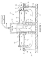
FIGURE 1 is a cross sectional view of a masking system. - As set forth herein, there is provided a system for masking a portion of a part, such as a turbine engine component, to be coated. The system described herein has durable metallic masking features that are free to expand and contract without distortion. These features are known as floating rings. These rings are relatively small and mostly, if not completely, coated with the part. The rings are not intended to provide full protection to the part; however, the rings do create the close tolerance edge feature which is needed. The rings work to hold tight tolerances because the rings come up to temperature during spray with the part while not being constrained by additional mask features that are not equally heated. The rings are easily replaceable since they are not fixed to their support structures.
- Further, the system described herein provides masking which is pressurized with air to create a leakage flow along the gap between the masking and the coating area. This is to help counter the flow of overspray material that deflects under the mask and prevent it from adhering to portions of the part being coated, such as the airfoils of an integrally bladed rotor (IBR). The air is supplied to the rotating part during spray through a rotary fitting located at a top portion of the masking system.
- Referring now to
Figure 1 , there is shown amasking system 10 for coating one ormore portions 14 of a part orturbine engine component 12 such as an IBR. As can be seen from the Figure, themasking system 10 includes a rotatablemetallic base 16 to which is mounted acentral support column 18. Therotatable base 16 may be secured to any suitable means (not shown) for rotating same. Fitted within thecentral support column 18 is afluid conduit 20. Thefluid conduit 20 is positioned on thebase 16. It may be mounted to the base if desired using any suitable fastening device known in the art. Thecomponent 12 to be coated has ahub 13 which allows the component to be placed over the exterior of thefluid conduit 20 and seated on anend 19 of thecentral support column 18. - As can be seen from
Figure 1 , thefluid conduit 20 has one ormore holes 22 which align with one ormore holes 24 in thecentral support column 18. The fluid conduit 20 mates with anair cap 26 which rotates with thebase 16. Not shown is a rotary union betweenair cap 26 and anair hose 28 which is connected to a source of pressurized air. - The
masking system 10 uses twoseparate masks component 12 to which a coating is not to be applied. Thelower mask 30 comprises an annularmetallic tube 32 which is positioned on thebase 16. Thetube 32, if desired, may be connected to thebase 16 using any suitable fastening device known in the art. Theannular tube 32 has anedge 34 on which anannular masking element 36 in the form of a flexible ring is positioned. If desired, theannular masking element 36 may be a single annular ring or may be a ring formed from a plurality ofsections 38 joined together by one ormore bolts 40 which allow the circumference of themasking element 36 to be adjusted so that themasking element 36 fits around theannular tube 32 and thecomponent 12. Since themasking element 36 is not fixed to thetube 12, it is free to expand and contract without distortion. Themasking element 36, as shown in the Figure, has anannular lip 42 which overlaps, but does not contact, a desired portion of thecomponent 12, such as theairfoils 44 on thecomponent 12. Theannular lip 42 may be integrally formed with thesections 38 or may be placed over thesections 38 so as to rest on thesections 38. Alternatively, if desired, theannular lip 42 may be joined to thesections 38 using any suitable fastening means known in the art. - The
masking system 10 further comprises anupper mask 50 which includes an annularmetallic plate 52 which has acentral opening 54 which allows theplate 52 to be positioned over thefluid conduit 20. Theplate 52 rests on afirst portion 56 of thecomponent 12 at an inner end and asecond portion 60 of thecomponent 12 at an outer end. As can be seen fromFigure 1 , theplate 52 has a downwardly dependingportion 53 which contacts theportion 56. Theupper mask 50 further comprises an outer masking element orflexible ring 58 which rests on anotherportion 60 of thecomponent 12. Theouter masking element 58 has afirst portion 59 which overlaps theportion 60 and which overlaps theplate 52. Theouter masking element 58 is positioned adjacent theplate 52 using a slip fit. Since it is not connected to theplate 52, theouter masking element 58 is free to expand and/or contract without distortion. - As shown in
Figure 1 , one ormore spray nozzles 62 are provided to coat theportion 14 of thecomponent 12. Thespray nozzles 62 aim the coating material towards thegap 64 between the lower andupper masks - Air is utilized to reduce overspraying of the coating material from adhering to the
airfoils 44. Pressurized air may be supplied to theconduit 20 via theair hose 28 and theair cap 26. Pressurized air flows through theinterior 21 of theconduit 20 and then into theinterior 31 of theannular tube 32 via theholes base 70 of theairfoils 40 and exits thetube 32 in the vicinity of thebase 70. In this way, the amount of any overspray adhering to theairfoils 44 is reduced. - While the various components of the masking system have been described as being metallic, they may also be made from any suitable material known in the art if desired. As noted above, the components of the masking system may all be formed from a metallic material such as cold rolled steel.
- The masking system described hereinbefore is beneficial in that it includes a tight tolerance part design which is easy to manufacture. Further, it provides cost savings by limiting the amount of manual part cleanup that is necessary after coating.
- There has been described in accordance with the present disclosure a dimensionally stable durable thermal spray masking system. While the dimensionally stable durable thermal spray masking system has been described in the context of a specific embodiment thereof, other unforeseeable alternatives, modifications, and variations may become apparent to those skilled in the art having read the foregoing description. Accordingly, it is intended to embrace those alternatives, modifications, and variations, as fall within the broad scope of the appended claims.
Claims (15)
- A masking system (10) for protecting portions of a part (12) to be coated, said masking system (10) comprising:a base (16);a conduit (20) mounted on said base (16), said part (12) to be coated being positioned over said conduit (20); andan annular plate (52) positioned over said conduit (20) and resting on a first portion (56) of said part (12).
- The masking system (10) according to claim 1, further comprising an outer masking element (58) positioned at an end of said annular plate (52).
- The masking system according to claim 2, wherein said outer masking element (58) rests on a second portion (60) of said part (12).
- The masking system (10) according to any of claims 1 to 3, further comprising:an annular tube (32) positioned on said base (16); andan annular masking element (36) positioned on an upper end of said annular tube (32).
- The masking system (10) according to claim 4, wherein said annular masking element (36) overlaps a plurality of airfoils (44) on said part (12).
- The masking system (10) according to claim 4 or 5, wherein said annular masking element (36) comprises a plurality of sections (38) joined together.
- The masking system (10) of any preceding claim, further comprising a support column (18) positioned on said base (16), said support column (18) surrounding said conduit.
- The masking system (10) of claim 7, wherein:said conduit (20) has a plurality of holes (22); andsaid support column (18) has a plurality of holes (24) aligned with the holes (22) in said conduit (20).
- The masking system (10) of claim 7 or 8, wherein said support column (18) supports an interior portion of said part (12) being coated.
- The masking system (10) of any preceding claim, further comprising a source of air connected to an interior of said conduit (20) via a fitting.
- The masking system of any preceding claim, wherein said base (16) is a rotatable base.
- A masking system (10) for protecting portions of a turbine engine component (12) being coated comprising:a central conduit (20) positioned on a base (16);an annular tube (32) positioned on said base (16);a turbine engine component (12) having a plurality of airfoils (44) positioned over said central conduit (20); andmeans for reducing overspraying adhering to said airfoils (44).
- The masking system (10) of claim 12, wherein said reducing means comprises means for creating a flow of pressurized air in said tube (32) which exits at a base (70) of said airfoils (44).
- The masking system (10) of claim 13, wherein said flow of pressurized air creating means comprising a source of pressurized air connected to said central conduit (20) and holes (22) in said central conduit (20) for introducing said pressurized air into said annular tube (32).
- The masking system (10) of any of claims 12 to 14, further comprising a top mask (50) for protecting a first portion of said turbine engine component (12) from being coated and a lower mask (30) mounted on said annular tube (32) for protecting said airfoils (44) from being coated.
Applications Claiming Priority (1)
| Application Number | Priority Date | Filing Date | Title |
|---|---|---|---|
| US12/956,288 US8468969B2 (en) | 2010-11-30 | 2010-11-30 | Dimensionally stable durable thermal spray masking system |
Publications (1)
| Publication Number | Publication Date |
|---|---|
| EP2458027A1 true EP2458027A1 (en) | 2012-05-30 |
Family
ID=45093503
Family Applications (1)
| Application Number | Title | Priority Date | Filing Date |
|---|---|---|---|
| EP11191271A Withdrawn EP2458027A1 (en) | 2010-11-30 | 2011-11-30 | Dimensionally stable durable thermal spray masking system |
Country Status (2)
| Country | Link |
|---|---|
| US (1) | US8468969B2 (en) |
| EP (1) | EP2458027A1 (en) |
Cited By (1)
| Publication number | Priority date | Publication date | Assignee | Title |
|---|---|---|---|---|
| EP4670852A1 (en) * | 2024-06-28 | 2025-12-31 | Chromalloy Gas Turbine LLC | HEAT SPRAY BOOTS AND HOLDER |
Families Citing this family (6)
| Publication number | Priority date | Publication date | Assignee | Title |
|---|---|---|---|---|
| TWI458557B (en) * | 2009-11-26 | 2014-11-01 | Hon Hai Prec Ind Co Ltd | Spray-paint shielding device and the method using the same |
| US20130136864A1 (en) * | 2011-11-28 | 2013-05-30 | United Technologies Corporation | Passive termperature control of hpc rotor coating |
| WO2014138416A1 (en) * | 2013-03-06 | 2014-09-12 | United Technologies Corporation | Fixturing for thermal spray coating of gas turbine components |
| US9956580B2 (en) | 2014-02-14 | 2018-05-01 | United Technologies Corporation | Spray masking for rotors |
| DE102015117424A1 (en) * | 2015-10-13 | 2017-04-13 | Rolls-Royce Deutschland Ltd & Co Kg | Covering device for attachment to a component |
| US20190078463A1 (en) | 2017-09-08 | 2019-03-14 | United Technologies Corporation | Segmented Ceramic Coatings and Methods |
Citations (4)
| Publication number | Priority date | Publication date | Assignee | Title |
|---|---|---|---|---|
| EP0965389A1 (en) * | 1998-06-17 | 1999-12-22 | United Technologies Corporation | Shield for masking a flow directing assembly |
| EP1630256A1 (en) * | 2004-07-30 | 2006-03-01 | United Technologies Corporation | Non-stick masking fixtures and methods of preparing same |
| EP1801360A2 (en) * | 2005-12-20 | 2007-06-27 | General Electric Company | Methods and apparatus for fabricating turbine engine components |
| US20090252872A1 (en) * | 2006-03-13 | 2009-10-08 | General Electric Company | Method and device to prevent coating a dovetail of a turbine airfoil |
Family Cites Families (3)
| Publication number | Priority date | Publication date | Assignee | Title |
|---|---|---|---|---|
| CH544274A (en) * | 1971-10-27 | 1973-11-15 | Balzers Patent Beteilig Ag | Device for cooling workpieces that are subjected to a treatment in a vacuum |
| US6037004A (en) * | 1997-12-19 | 2000-03-14 | United Technologies Corporation | Shield and method for protecting an airfoil surface |
| DE10356679A1 (en) * | 2003-11-28 | 2005-07-21 | Rolls-Royce Deutschland Ltd & Co Kg | Process and apparatus for coating or heat treating BLISK aircraft gas turbine disks |
-
2010
- 2010-11-30 US US12/956,288 patent/US8468969B2/en not_active Expired - Fee Related
-
2011
- 2011-11-30 EP EP11191271A patent/EP2458027A1/en not_active Withdrawn
Patent Citations (4)
| Publication number | Priority date | Publication date | Assignee | Title |
|---|---|---|---|---|
| EP0965389A1 (en) * | 1998-06-17 | 1999-12-22 | United Technologies Corporation | Shield for masking a flow directing assembly |
| EP1630256A1 (en) * | 2004-07-30 | 2006-03-01 | United Technologies Corporation | Non-stick masking fixtures and methods of preparing same |
| EP1801360A2 (en) * | 2005-12-20 | 2007-06-27 | General Electric Company | Methods and apparatus for fabricating turbine engine components |
| US20090252872A1 (en) * | 2006-03-13 | 2009-10-08 | General Electric Company | Method and device to prevent coating a dovetail of a turbine airfoil |
Cited By (1)
| Publication number | Priority date | Publication date | Assignee | Title |
|---|---|---|---|---|
| EP4670852A1 (en) * | 2024-06-28 | 2025-12-31 | Chromalloy Gas Turbine LLC | HEAT SPRAY BOOTS AND HOLDER |
Also Published As
| Publication number | Publication date |
|---|---|
| US8468969B2 (en) | 2013-06-25 |
| US20120132138A1 (en) | 2012-05-31 |
Similar Documents
| Publication | Publication Date | Title |
|---|---|---|
| US8468969B2 (en) | Dimensionally stable durable thermal spray masking system | |
| EP1600608B1 (en) | Gas turbine impingement cooling structure and method of impingement cooling | |
| US8177493B2 (en) | Airtight external shroud for a turbomachine turbine wheel | |
| EP2710231B1 (en) | Seals for a gas turbine combustion system transition duct | |
| JP6496499B2 (en) | Turbine component and method of assembling it | |
| EP2604804B1 (en) | Blade tip clearance control | |
| EP2944768B1 (en) | Distributor device for cooling air within an engine | |
| CA2619516A1 (en) | Combustor with chamfered dome | |
| US9670791B2 (en) | Flexible finger seal for sealing a gap between turbine engine components | |
| CN109779697A (en) | Active clearance with finger portion controls cooling air track | |
| EP2027932B1 (en) | Masking fixture for a coating process | |
| US8282356B2 (en) | Apparatus and method for reducing wear in disk lugs | |
| US6485655B1 (en) | Method and apparatus for retaining an internal coating during article repair | |
| EP3179043B1 (en) | Turbine component comprising a cooling passage embedded within the coating | |
| CN116423146B (en) | Tool for repairing flow passage of axial-flow casing of aero-engine easy to assemble and application method of tool | |
| US9126278B2 (en) | Template for forming cooling passages in a turbine engine component | |
| US10527288B2 (en) | Small exit duct for a reverse flow combustor with integrated cooling elements | |
| US9476322B2 (en) | Combustor transition duct assembly with inner liner | |
| CN111201370A (en) | Elements for distributing cooling fluid and associated turbine ring assemblies | |
| US6645299B2 (en) | Method and assembly for masking | |
| US11306613B2 (en) | Turbocharger | |
| US9759231B2 (en) | Mid-frame for a gas turbine and gas turbine | |
| CN107931952B (en) | Auxiliary device for aircraft engine casing assembly | |
| EP3112592B1 (en) | Gas turbine blade | |
| JP4995557B2 (en) | Assembly comprising a turbine engine component |
Legal Events
| Date | Code | Title | Description |
|---|---|---|---|
| PUAI | Public reference made under article 153(3) epc to a published international application that has entered the european phase |
Free format text: ORIGINAL CODE: 0009012 |
|
| AK | Designated contracting states |
Kind code of ref document: A1 Designated state(s): AL AT BE BG CH CY CZ DE DK EE ES FI FR GB GR HR HU IE IS IT LI LT LU LV MC MK MT NL NO PL PT RO RS SE SI SK SM TR |
|
| AX | Request for extension of the european patent |
Extension state: BA ME |
|
| 17P | Request for examination filed |
Effective date: 20121120 |
|
| STAA | Information on the status of an ep patent application or granted ep patent |
Free format text: STATUS: THE APPLICATION IS DEEMED TO BE WITHDRAWN |
|
| 18D | Application deemed to be withdrawn |
Effective date: 20140603 |