EP2457704A1 - Cutting device for absorbent article band body - Google Patents
Cutting device for absorbent article band body Download PDFInfo
- Publication number
- EP2457704A1 EP2457704A1 EP10802187A EP10802187A EP2457704A1 EP 2457704 A1 EP2457704 A1 EP 2457704A1 EP 10802187 A EP10802187 A EP 10802187A EP 10802187 A EP10802187 A EP 10802187A EP 2457704 A1 EP2457704 A1 EP 2457704A1
- Authority
- EP
- European Patent Office
- Prior art keywords
- negative pressure
- positive
- port
- roll
- holding
- Prior art date
- Legal status (The legal status is an assumption and is not a legal conclusion. Google has not performed a legal analysis and makes no representation as to the accuracy of the status listed.)
- Withdrawn
Links
Images





Classifications
-
- A—HUMAN NECESSITIES
- A61—MEDICAL OR VETERINARY SCIENCE; HYGIENE
- A61F—FILTERS IMPLANTABLE INTO BLOOD VESSELS; PROSTHESES; DEVICES PROVIDING PATENCY TO, OR PREVENTING COLLAPSING OF, TUBULAR STRUCTURES OF THE BODY, e.g. STENTS; ORTHOPAEDIC, NURSING OR CONTRACEPTIVE DEVICES; FOMENTATION; TREATMENT OR PROTECTION OF EYES OR EARS; BANDAGES, DRESSINGS OR ABSORBENT PADS; FIRST-AID KITS
- A61F13/00—Bandages or dressings; Absorbent pads
- A61F13/15—Absorbent pads, e.g. sanitary towels, swabs or tampons for external or internal application to the body; Supporting or fastening means therefor; Tampon applicators
- A61F13/15577—Apparatus or processes for manufacturing
- A61F13/15707—Mechanical treatment, e.g. notching, twisting, compressing, shaping
- A61F13/15723—Partitioning batts; Cutting
-
- B—PERFORMING OPERATIONS; TRANSPORTING
- B26—HAND CUTTING TOOLS; CUTTING; SEVERING
- B26D—CUTTING; DETAILS COMMON TO MACHINES FOR PERFORATING, PUNCHING, CUTTING-OUT, STAMPING-OUT OR SEVERING
- B26D1/00—Cutting through work characterised by the nature or movement of the cutting member or particular materials not otherwise provided for; Apparatus or machines therefor; Cutting members therefor
- B26D1/01—Cutting through work characterised by the nature or movement of the cutting member or particular materials not otherwise provided for; Apparatus or machines therefor; Cutting members therefor involving a cutting member which does not travel with the work
- B26D1/12—Cutting through work characterised by the nature or movement of the cutting member or particular materials not otherwise provided for; Apparatus or machines therefor; Cutting members therefor involving a cutting member which does not travel with the work having a cutting member moving about an axis
- B26D1/25—Cutting through work characterised by the nature or movement of the cutting member or particular materials not otherwise provided for; Apparatus or machines therefor; Cutting members therefor involving a cutting member which does not travel with the work having a cutting member moving about an axis with a non-circular cutting member
- B26D1/34—Cutting through work characterised by the nature or movement of the cutting member or particular materials not otherwise provided for; Apparatus or machines therefor; Cutting members therefor involving a cutting member which does not travel with the work having a cutting member moving about an axis with a non-circular cutting member moving about an axis parallel to the line of cut
- B26D1/40—Cutting through work characterised by the nature or movement of the cutting member or particular materials not otherwise provided for; Apparatus or machines therefor; Cutting members therefor involving a cutting member which does not travel with the work having a cutting member moving about an axis with a non-circular cutting member moving about an axis parallel to the line of cut and coacting with a rotary member
- B26D1/405—Cutting through work characterised by the nature or movement of the cutting member or particular materials not otherwise provided for; Apparatus or machines therefor; Cutting members therefor involving a cutting member which does not travel with the work having a cutting member moving about an axis with a non-circular cutting member moving about an axis parallel to the line of cut and coacting with a rotary member for thin material, e.g. for sheets, strips or the like
-
- B—PERFORMING OPERATIONS; TRANSPORTING
- B26—HAND CUTTING TOOLS; CUTTING; SEVERING
- B26D—CUTTING; DETAILS COMMON TO MACHINES FOR PERFORATING, PUNCHING, CUTTING-OUT, STAMPING-OUT OR SEVERING
- B26D7/00—Details of apparatus for cutting, cutting-out, stamping-out, punching, perforating, or severing by means other than cutting
- B26D7/18—Means for removing cut-out material or waste
- B26D7/1845—Means for removing cut-out material or waste by non mechanical means
- B26D7/1863—Means for removing cut-out material or waste by non mechanical means by suction
-
- B—PERFORMING OPERATIONS; TRANSPORTING
- B26—HAND CUTTING TOOLS; CUTTING; SEVERING
- B26F—PERFORATING; PUNCHING; CUTTING-OUT; STAMPING-OUT; SEVERING BY MEANS OTHER THAN CUTTING
- B26F1/00—Perforating; Punching; Cutting-out; Stamping-out; Apparatus therefor
- B26F1/38—Cutting-out; Stamping-out
- B26F1/384—Cutting-out; Stamping-out using rotating drums
-
- B—PERFORMING OPERATIONS; TRANSPORTING
- B26—HAND CUTTING TOOLS; CUTTING; SEVERING
- B26D—CUTTING; DETAILS COMMON TO MACHINES FOR PERFORATING, PUNCHING, CUTTING-OUT, STAMPING-OUT OR SEVERING
- B26D3/00—Cutting work characterised by the nature of the cut made; Apparatus therefor
- B26D3/10—Making cuts of other than simple rectilinear form
-
- Y—GENERAL TAGGING OF NEW TECHNOLOGICAL DEVELOPMENTS; GENERAL TAGGING OF CROSS-SECTIONAL TECHNOLOGIES SPANNING OVER SEVERAL SECTIONS OF THE IPC; TECHNICAL SUBJECTS COVERED BY FORMER USPC CROSS-REFERENCE ART COLLECTIONS [XRACs] AND DIGESTS
- Y10—TECHNICAL SUBJECTS COVERED BY FORMER USPC
- Y10T—TECHNICAL SUBJECTS COVERED BY FORMER US CLASSIFICATION
- Y10T83/00—Cutting
- Y10T83/202—With product handling means
- Y10T83/2066—By fluid current
- Y10T83/207—By suction means
Definitions
- the present invention relates to a cutting apparatus for a strip-like body of absorbent articles.
- a cutting apparatus including a cutter roll and an anvil roll which rotate about the axes of rotation nearly in parallel with each other and in the directions opposite to each other, in which a strip-like body of absorbent articles fed to between the cutter roll and the anvil roll is cut into a product portion and a trim by a blade provided on the cutter roll, wherein the cutter roll is constituted by a holding roll capable of temporarily holding the trim, the holding roll having circumferential ports formed in the circumferential surface thereof, a side port formed in the side surface thereof and a communication passage for communicating the circumferential ports with the side port, wherein the cutting apparatus includes a negative pressure manifold having a negative pressure chamber connected to a negative pressure source, the negative pressure manifold having, in the side surface thereof, a negative pressure port communicated with the negative pressure chamber, and the negative pressure manifold being so fixed that the side surface thereof faces the side surface of the holding roll, wherein the communication and shut-off between the side port of the holding roll and the negative pressure port are changed over accompanying the rotation of the holding
- the above cutting apparatus is provided with sealing means such as packing between the side surface of the holding roll and the side surface of the negative pressure manifold by taking the slidability into account.
- the holding roll i.e., the cutter roll rotates at a high speed and in contact with the sealing means and thus the heat of friction is produced.
- the cutter roll may gradually expand thermally due to the heat of friction and may deform.
- the cutter that is deformed may cause defective cutting in which the strip may not be sufficiently cut. If the contact pressure is elevated between the cutter roll and the anvil roll in order to avoid defective cutting, then the life of the blade of the cutter roll may decrease.
- a cutting apparatus comprising a cutter roll and an anvil roll which rotate about the axes of rotation nearly in parallel with each other and in the directions opposite to each other, in which a strip-like body of absorbent articles fed to between the cutter roll and the anvil roll is cut into a plurality of cut portions by a blade provided on the cutter roll, wherein: either one or both of the cutter roll and the anvil roll are constituted by a holding roll capable of temporarily holding the cut portion, the holding roll having a circumferential port formed in the circumferential surface thereof, a side port formed in the side surface thereof and a communication passage for communicating the circumferential port and the side port with each other; the cutting apparatus comprises a positive/negative pressure manifold having a positive pressure chamber connected to a positive pressure source and a negative pressure chamber connected to a negative pressure source, the positive/negative pressure manifold having, in one side surface thereof, a positive pressure port communicated with the positive pressure chamber and a negative pressure port communicated with the negative pressure chamber, and
- Fig. 1 shows a cutting apparatus 1 according to a first embodiment of the present invention.
- the cutting apparatus 1 is for cutting a strip-like body of absorbent articles into a plurality of cut portions.
- the cut portion comprises an absorbent article and a trim, i.e., the strip is cut into absorbent articles and trims which are then separated.
- the absorbent article comprises a top sheet, a back sheet and an absorbent body arranged between the top sheet and the back sheet, and is, for example, a sanitary napkin, a panty liner, an incontinence pad or a diaper.
- the cutting apparatus 1 includes a cutter roll 2 and an anvil roll 3 arranged in the vertical direction.
- the cutter roll 2 and the anvil roll 3 are supported to rotate about the axes of rotation L and M in nearly the horizontal direction relative to the frame 2, and, therefore, are allowed to rotate about the axes of rotation L and M which are in nearly parallel with each other.
- the cutter roll 2 and the anvil roll 3 are rotated by a drive unit (not shown) in the directions opposite to each other.
- the cutter roll 2 includes a main body 2a and a shaft body 2b.
- the cutter roll 2 is provided with flanges 2c on both sides of the main body 2a, and the flanges 2c are in contact with the circumferential surface of the main body 3a of the anvil roll 3. Further, the main body 2a is provided on a circumferential surface 2d thereof with, for example, a pair of blades 2e for cutting the strip. A holding region 2f is formed on a region surrounded by the blades 2e on the circumferential surface 2d to temporarily hold a cut portion. A plurality of circumferential ports 2g are formed in the holding region 2f being aligned along, for example, the axis of rotation L.
- a side port 2i is formed in one side surface 2h of the main body 2a of the cutter roll 2.
- the circumferential ports 2g and the side port 2i are communicated with each other through a communication passage 2j that penetrates through the main body 2a.
- a recovery device 5 is arranged over the cutter roll 2 to recover the trims held by the cutter roll 2.
- the recovery device 5 is connected to a negative pressure source (not shown).
- a positive/negative pressure manifold 6 is arranged so that it faces the one side surface 2h of the cutter roll 2 while it is not rotatable.
- the positive/negative pressure manifold 6 has a through hole 6a that penetrates through the center thereof and, therefore, assumes the shape of a ring.
- the positive/negative pressure manifold 6, further, includes a positive pressure chamber 6c which is connected to a positive pressure source (not shown) at all times through a connection port 6b and a negative pressure chamber 6e which is connected to a negative pressure source (not shown) at all times through a connection port 6d.
- the positive/negative pressure manifold 6 further, has a positive pressure port 6g of an arcuate shape communicated with the positive pressure chamber 6c and a negative pressure port 6h of an arcuate shape communicated with the negative pressure chamber 6e, the positive pressure port 6g and the negative pressure port 6h being formed in one side surface 6f of the positive/negative pressure manifold 6 facing the one side surface 2h of the cutter roll 2.
- the radial positions of the positive pressure port 6g and the negative pressure port 6h from the axis of rotation L are nearly equal to each other, and are also nearly equal to the radial position of the side port 2i of the cutter roll 2 from the axis of rotation L.
- the side port 2i When the side port 2i faces the negative pressure port 6h accompanying the rotation of the cutter roll 2, the side port 2i communicates with the negative pressure port 6h, and the negative pressure in the negative pressure chamber 6e is applied into the circumferential ports 2g. Similarly, when the side port 2i faces the positive pressure port 6g, the side port 2i communicates with the positive pressure port 6g, and the positive pressure in the positive pressure chamber 6c is applied into the circumferential ports 2g. On the other hand, as the cutter roll 2 rotates further and the side port 2i no longer faces the negative pressure port 6h, the side port 2i is shut off from the negative pressure port 6h.
- the negative pressure port 6h is so formed that the side port 2i faces thereto over a rotational angular range in which the holding region 2f comes to face the anvil roll 3 and moves up to arriving at the recovery device 5.
- the positive pressure port 6g is so formed that the side port 2i faces thereto over a rotational angular range in which the holding region 2f faces the recovery device 5.
- the positive/negative pressure manifold 6 is so fixed that a slight gap 7 is formed between the one side surface 2h of the cutter roll 2 and the one side surface 6f of the positive/negative pressure manifold 6. Namely, the cutter roll 2 and the positive/negative pressure manifold 6 do not come in contact with each other.
- the one side surface 2h and the one side surface 6f are both flat.
- a fixing member 8 of a ring-like shape having a cylindrical portion 8a is fixed to the frame 4.
- the positive/negative pressure manifold 6 is arranged surrounding the cylindrical portion 8a, and is fixed to the cylindrical portion 8a by a screw 8b.
- the shaft body 2b of the cutter roll 2 penetrates through the through hole 6a of the positive/negative pressure manifold 6 and the through hole of the fixing member 8, and is supported by the frame 4.
- the position of the positive/negative pressure manifold 6 with respect to the fixing member 8 can be adjusted in the direction of the axis of rotation L and, therefore, a magnitude of the gap 7 can be adjusted.
- the strip-like body of absorbent articles is conveyed by a conveyer in nearly a horizontal direction, and is fed to the cutting apparatus 1 or, concretely, to between the cutter roll 2 and the anvil rill 3.
- the blades 2e reach the strip accompanying the rotation of the cutter roll 2, the strip is cut into an absorbent article A and a trim T as shown in Fig. 7 .
- the absorbent article A is then conveyed by a conveyer (not shown) in nearly a horizontal direction.
- the side port 2i of the cutter roll 2 is in communication with the negative pressure port 6h of the positive/negative pressure manifold 6 (see Fig. 3 ). At this moment, therefore, the negative pressure is applied into the circumferential ports 2g, and the trim T is held in the holding region 2f of the cutter roll 2 due to the negative pressure or the suction force. As the cutter roll 2 rotates further, the trim T is conveyed toward the recovery device 5. When the holding region 2f arrives at the recovery device 5, the side port 2i is shut off from the negative pressure port 6h but is communicated with the positive pressure port 6g (see Fig. 3 ) whereby the positive pressure is applied into the circumferential ports 2g. As a result, the trim T that had been held by the holding region 2f now separates away from the holding region 2f, and is recovered in the recovery device 5 due to the negative pressure or the suction force of the recovery device 5.
- the slight gap 7 is formed between the cutter roll 2 and the positive/negative pressure manifold 6. This means that no heat of friction is generated by the contact with the positive/negative pressure manifold 6, and the cutter roll 2 is reliably prevented from being thermally expanded.
- the air flow is generated in the gap 7 due to the positive pressure applied into the positive pressure port 6g and the negative pressure applied into the negative pressure port 6h. Namely, the air flowing out from the positive pressure port 6g flows through the gap 7 or the air in the gap 7 flows into the negative pressure port 6h. Therefore, the cutter roll 2 is cooled by the air flow. Accordingly, the cutter roll 2 is further prevented from being thermally expanded. As a result, it is made possible to reliably suppress the defective cutting caused by the cutter roll 2 that is thermally expanded.
- the fact that the air flow is generated in the gap 7 means that the positive pressure or the negative pressure is leaking. Therefore, the positive pressure or the negative pressure applied to the circumferential ports 2g may be weakened, and the trim T may not be reliably held or may separate away. It is therefore necessary to suppress the air flow generated in the gap 7 or the leakage.
- the air flow in the gap 7 can be suppressed in a manner, for example, as described below.
- ring-like projections 9 are formed on one side surface 6f of the positive/negative pressure manifold 6 so as to project toward the one side surface 2h of the cutter roll 2.
- the projections 9 extend in concentric on the outer side and the inner side in the radial direction so as to surround the positive pressure port 6g and the negative pressure port 6h. As a result, the air flow in the gap 7 can be suppressed.
- the one side surface 2h of the cutter roll 2 is flat.
- the projections 9 may not be of the shape of a ring.
- the projection 9 extends in an arcuate shape so as to surround the positive pressure port 6g and the negative pressure port 6h.
- a partition wall 9a is formed between the positive pressure port 6g and the negative pressure port 6h. The partition wall 9a suppresses the air flow from the positive pressure port 6g to the negative pressure port 6h through the gap 7.
- the projection 9 or the partition wall 9a may be formed on the one side surface 2h of the cutter roll 2, as a matter of course.
- ring-like recesses 10 are formed in one side surface 2h of the cutter roll 2, and the projections 9 are received in the recesses 10.
- projections 11 similar to the projections 9 are formed on one side surface 2h of the cutter roll 2
- recesses 12 similar to the recesses 10 are formed in one side surface 6f of the positive/negative pressure manifold 6, and the projections 11 are received in the recesses 12. This enables the positive pressure or the negative pressure to be more reliably applied into the circumferential ports 2g.
- projections 9 are formed on one side surface 6f of the positive/negative pressure manifold 6, and projections 11 are formed on one side surface 2h of the cutter roll 2. Further, the projections 9 are received in a recess 13 defined in one surface 2h on the inner sides of the projections 11, and the projections 11 are received in a recess 14 defined in one side surface 6f on the outer sides of the projections 9.
- the radial positions of the positive pressure port 6g and the negative pressure ports 6h are different from each other.
- ring-shaped projections 9 are formed on the radially outer side of the positive pressure port 6g, between the positive pressure port 6g and the negative pressure port 6h, and on the radially inner side of the negative pressure port 6h. This suppresses the air flow from the positive pressure port 6g to the negative pressure port 6h, too.
- the side port 2i is so dimensioned that it can be communicated with both the positive pressure port 6g and the negative pressure port 6h.
- a ring-like projection 15 is formed along the outer circumferential edge of the one side surface 6f of the positive/negative pressure manifold 6, and an outer circumferential edge 16 of the one side surface 2h of the cutter roll 2 is surrounded by the projection 15. This also makes it possible to suppress the air flow in the gap 7.
- the projection 15 may not be of the shape of a ring and is, for example, of an arcuate shape.
- a ring-like dent 17 is formed in the one side surface 2h of the cutter roll 2 along the outer circumferential edge 16, and the projection 15 is received in the dent 17.
- the dent 17 can also be formed by attaching a disk member of a reduced diameter to the side surfaces of flanges 2c of the cutter roll 2.
- the outer circumferential edge of the disk member constitutes the outer circumferential edge 16 of the one side surface 2h of the cutter roll 2.
- a ring-like projection 18 is formed along the outer circumferential edge of one side surface 2h of the cutter roll 2, and the outer circumferential edge 19 of the one side surface 6f of the positive/negative pressure manifold 6 is surrounded by the projection 18.
- the trims T are separated from each other.
- the absorbent articles A are cut out from the strip the trims T continues like a strip.
- the present invention can also be applied in this case.
- the holding regions 2f are formed on the outer circumferential sides of the blades 2e.
- the trim T is held by the cutter roll 2.
- the trim T may be held by the anvil roll 3.
- either one of the absorbent article A or the trim T may be held by the cutter roll 2 and the other one may be held by the anvil roll 3.
- Fig. 17 shows an eleventh embodiment in which the absorbent article A is held by the cutter roll 2 and the trim T is held by the anvil roll 3.
- a positive/negative pressure manifold 20 is fixed facing the one side surface of the anvil roll 3.
- a holding region 21 is also formed on the circumferential surface of the anvil roll 3, and the positive pressure or the negative pressure is applied into circumferential ports formed in the holding region 21 from the positive/negative pressure manifold 20. In this case, a slight gap can be maintained between the one side surface of the anvil roll 3 and the one side surface of the positive/negative pressure manifold 20 facing to each other.
- a roll capable of temporarily holding the cut portion is referred to as a holding roll, then it can be the that either one or both of the cutter roll 2 and the anvil roll 3 are constituted by the holding rolls.
- a slight gap is formed between the one side surface of the holding roll and the one side surface of the positive/negative pressure manifold that are facing each other.
- the positive/negative pressure manifold 6 is assuming the shape of a ring. As shown in Fig. 18 depicting a twelfth embodiment, however, a notch 6i of, for example, a sector shape may be formed in the positive/negative pressure manifold 6 at a position where neither the positive pressure chamber 6c nor the negative pressure chamber 6e has been formed. This permits the one side surface 6f of the cutter roll 2 to be exposed promoting the radiation of heat from the one side surface 6f. Moreover, the positive/negative pressure manifold 6 can be produced using a material in a decreased amount, and the weight thereof can be decreased.
- the positive/negative pressure manifold 20 can be constituted in the same manner, as a matter of course.
- the projections 9 can be formed on the one side surface 6f of the positive/negative pressure manifold 6, and the projection 15 can be formed along the outer circumferential edge of the one side surface 6f thereof.
Landscapes
- Engineering & Computer Science (AREA)
- Mechanical Engineering (AREA)
- Life Sciences & Earth Sciences (AREA)
- Health & Medical Sciences (AREA)
- Forests & Forestry (AREA)
- Heart & Thoracic Surgery (AREA)
- Epidemiology (AREA)
- Biomedical Technology (AREA)
- Manufacturing & Machinery (AREA)
- Vascular Medicine (AREA)
- Animal Behavior & Ethology (AREA)
- General Health & Medical Sciences (AREA)
- Public Health (AREA)
- Veterinary Medicine (AREA)
- Perforating, Stamping-Out Or Severing By Means Other Than Cutting (AREA)
- Absorbent Articles And Supports Therefor (AREA)
Abstract
Description
- The present invention relates to a cutting apparatus for a strip-like body of absorbent articles.
- A cutting apparatus including a cutter roll and an anvil roll which rotate about the axes of rotation nearly in parallel with each other and in the directions opposite to each other, in which a strip-like body of absorbent articles fed to between the cutter roll and the anvil roll is cut into a product portion and a trim by a blade provided on the cutter roll, wherein the cutter roll is constituted by a holding roll capable of temporarily holding the trim, the holding roll having circumferential ports formed in the circumferential surface thereof, a side port formed in the side surface thereof and a communication passage for communicating the circumferential ports with the side port, wherein the cutting apparatus includes a negative pressure manifold having a negative pressure chamber connected to a negative pressure source, the negative pressure manifold having, in the side surface thereof, a negative pressure port communicated with the negative pressure chamber, and the negative pressure manifold being so fixed that the side surface thereof faces the side surface of the holding roll, wherein the communication and shut-off between the side port of the holding roll and the negative pressure port are changed over accompanying the rotation of the holding roll, and when the side port of the holding roll is communicated with the negative pressure port, a negative pressure is applied into the circumferential ports of the holding roll causing the trim to be held by the holding roll is widely known (see PLT 1).
- The above cutting apparatus is provided with sealing means such as packing between the side surface of the holding roll and the side surface of the negative pressure manifold by taking the slidability into account.
-
- Patent Literature:
- PLT 1: Japanese Unexamined Patent Publication No.
2008-237796
- PLT 1: Japanese Unexamined Patent Publication No.
- However, the holding roll, i.e., the cutter roll rotates at a high speed and in contact with the sealing means and thus the heat of friction is produced. The cutter roll may gradually expand thermally due to the heat of friction and may deform. The cutter that is deformed may cause defective cutting in which the strip may not be sufficiently cut. If the contact pressure is elevated between the cutter roll and the anvil roll in order to avoid defective cutting, then the life of the blade of the cutter roll may decrease.
- According to the present invention, there is provided a cutting apparatus comprising a cutter roll and an anvil roll which rotate about the axes of rotation nearly in parallel with each other and in the directions opposite to each other, in which a strip-like body of absorbent articles fed to between the cutter roll and the anvil roll is cut into a plurality of cut portions by a blade provided on the cutter roll, wherein: either one or both of the cutter roll and the anvil roll are constituted by a holding roll capable of temporarily holding the cut portion, the holding roll having a circumferential port formed in the circumferential surface thereof, a side port formed in the side surface thereof and a communication passage for communicating the circumferential port and the side port with each other; the cutting apparatus comprises a positive/negative pressure manifold having a positive pressure chamber connected to a positive pressure source and a negative pressure chamber connected to a negative pressure source, the positive/negative pressure manifold having, in one side surface thereof, a positive pressure port communicated with the positive pressure chamber and a negative pressure port communicated with the negative pressure chamber, and the positive/negative pressure manifold being so fixed that the one side surface thereof faces the one side surface of the holding roll; the communication and shut-off between the side port of the holding roll and the positive pressure port/negative pressure port are changed over accompanying the rotation of the holding roll, when the side port of the holding roll is communicated with the negative pressure port, a negative pressure is applied into the circumferential port of the holding roll causing the cut portion to be held by the holding roll and when the side port of the holding roll is communicated with the positive pressure port, a positive pressure is applied into the circumferential port of the holding roll causing the cut portion being held to separate away from the holding roll; and a slight gap is formed between the one side surface of the holding roll and the one side surface of the positive/negative pressure manifold that are facing each other.
- It is possible to suppress the defective cutting that results from the thermal expansion of the holding roll.
-
-
Fig. 1 is a general view of a cutting apparatus illustrating a first embodiment of the present invention. -
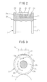
Fig. 2 is a partly sectional front view of a cutter roll shown inFig. 1 . -
Fig. 3 is a side view of the cutter roll shown inFig. 1 . -
Fig. 4 is a perspective view of a positive/negative pressure manifold shown inFig. 1 . -
Fig. 5 is a partly enlarged section view of the cutter roll and the positive/negative pressure manifold shown inFig. 1 . -
Fig. 6 is a partly disassembled view of the cutting apparatus shown inFig. 1 . -
Fig. 7 is a schematic perspective view illustrating the operation of the cutting apparatus shown inFig. 1 . -
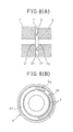
Fig. 8(A) is a partly enlarged sectional view of the cutter roll and the positive/negative pressure manifold illustrating a second embodiment of the present invention. -
Fig. 8(B) is a side view of the positive/negative pressure manifold illustrating the second embodiment of the present invention. -
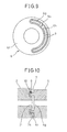
Fig. 9 is a side view of the positive/negative pressure manifold illustrating a third embodiment of the present invention. -
Fig. 10 is a partly enlarged sectional view of the cutter roll and the positive/negative pressure manifold illustrating a fourth embodiment of the present invention. -
Fig. 11 is a partly enlarged sectional view of the cutter roll and the positive/negative pressure manifold illustrating a fifth embodiment of the present invention. -
Fig. 12 is a partly enlarged sectional view of the cutter roll and the positive/negative pressure manifold illustrating a sixth embodiment of the present invention. -
Fig. 13 is a partly enlarged sectional view of the cutter roll and the positive/negative pressure manifold illustrating a seventh embodiment of the present invention. -
Fig. 14 is a partly enlarged view of the cutter roll and the positive/negative pressure manifold illustrating an eighth embodiment of the present invention. -
Fig. 15 is a partly enlarged view of the cutter roll and the positive/negative pressure manifold illustrating a ninth embodiment of the present invention. -
Fig. 16 is a partly enlarged view of the cutter roll and the positive/negative pressure manifold illustrating a tenth embodiment of the present invention. -
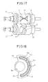
Fig. 17 is a schematic perspective view illustrating the operation of the cutting apparatus according to an eleventh embodiment of the present invention. -
Fig. 18 is a side view of the positive/negative pressure manifold illustrating a twelfth embodiment of the present invention. -
Fig. 1 shows a cutting apparatus 1 according to a first embodiment of the present invention. The cutting apparatus 1 is for cutting a strip-like body of absorbent articles into a plurality of cut portions. According to an embodiment of the present invention, the cut portion comprises an absorbent article and a trim, i.e., the strip is cut into absorbent articles and trims which are then separated. The absorbent article comprises a top sheet, a back sheet and an absorbent body arranged between the top sheet and the back sheet, and is, for example, a sanitary napkin, a panty liner, an incontinence pad or a diaper. - Referring to
Fig. 1 , the cutting apparatus 1 includes acutter roll 2 and ananvil roll 3 arranged in the vertical direction. Thecutter roll 2 and theanvil roll 3 are supported to rotate about the axes of rotation L and M in nearly the horizontal direction relative to theframe 2, and, therefore, are allowed to rotate about the axes of rotation L and M which are in nearly parallel with each other. Thecutter roll 2 and theanvil roll 3 are rotated by a drive unit (not shown) in the directions opposite to each other. - The
cutter roll 2 includes amain body 2a and ashaft body 2b. Theanvil roll 3, too, includes a main body 3a and a shaft body 3b. - The
cutter roll 2 is provided with flanges 2c on both sides of themain body 2a, and the flanges 2c are in contact with the circumferential surface of the main body 3a of theanvil roll 3. Further, themain body 2a is provided on acircumferential surface 2d thereof with, for example, a pair ofblades 2e for cutting the strip. Aholding region 2f is formed on a region surrounded by theblades 2e on thecircumferential surface 2d to temporarily hold a cut portion. A plurality ofcircumferential ports 2g are formed in theholding region 2f being aligned along, for example, the axis of rotation L. - As shown in
Figs. 2 and 3 , further, a side port 2i is formed in oneside surface 2h of themain body 2a of thecutter roll 2. Thecircumferential ports 2g and the side port 2i are communicated with each other through acommunication passage 2j that penetrates through themain body 2a. - Reverting to
Fig. 1 , arecovery device 5 is arranged over thecutter roll 2 to recover the trims held by thecutter roll 2. Therecovery device 5 is connected to a negative pressure source (not shown). Further, a positive/negative pressure manifold 6 is arranged so that it faces the oneside surface 2h of thecutter roll 2 while it is not rotatable. - As shown in
Fig. 4 , the positive/negative pressure manifold 6 has a throughhole 6a that penetrates through the center thereof and, therefore, assumes the shape of a ring. The positive/negative pressure manifold 6, further, includes apositive pressure chamber 6c which is connected to a positive pressure source (not shown) at all times through aconnection port 6b and anegative pressure chamber 6e which is connected to a negative pressure source (not shown) at all times through aconnection port 6d. The positive/negative pressure manifold 6, further, has apositive pressure port 6g of an arcuate shape communicated with thepositive pressure chamber 6c and anegative pressure port 6h of an arcuate shape communicated with thenegative pressure chamber 6e, thepositive pressure port 6g and thenegative pressure port 6h being formed in oneside surface 6f of the positive/negative pressure manifold 6 facing the oneside surface 2h of thecutter roll 2. In this case, as also shown inFig. 3 , the radial positions of thepositive pressure port 6g and thenegative pressure port 6h from the axis of rotation L are nearly equal to each other, and are also nearly equal to the radial position of the side port 2i of thecutter roll 2 from the axis of rotation L. - When the side port 2i faces the
negative pressure port 6h accompanying the rotation of thecutter roll 2, the side port 2i communicates with thenegative pressure port 6h, and the negative pressure in thenegative pressure chamber 6e is applied into thecircumferential ports 2g. Similarly, when the side port 2i faces thepositive pressure port 6g, the side port 2i communicates with thepositive pressure port 6g, and the positive pressure in thepositive pressure chamber 6c is applied into thecircumferential ports 2g. On the other hand, as thecutter roll 2 rotates further and the side port 2i no longer faces thenegative pressure port 6h, the side port 2i is shut off from thenegative pressure port 6h. Similarly, when the side port 2i no longer faces thepositive pressure port 6g, the side port 2i is shut off from thepositive pressure port 6g. Thus, the communication and shut-off of the side port 2i are changed over relative to thenegative pressure port 6h and thepositive pressure port 6g accompanying the rotation of thecutter roll 2. - According to an embodiment of the present invention, as will be learned from
Fig. 3 , too, thenegative pressure port 6h is so formed that the side port 2i faces thereto over a rotational angular range in which the holdingregion 2f comes to face theanvil roll 3 and moves up to arriving at therecovery device 5. Further, thepositive pressure port 6g is so formed that the side port 2i faces thereto over a rotational angular range in which the holdingregion 2f faces therecovery device 5. - As shown in
Fig. 5 , the positive/negative pressure manifold 6 is so fixed that aslight gap 7 is formed between the oneside surface 2h of thecutter roll 2 and the oneside surface 6f of the positive/negative pressure manifold 6. Namely, thecutter roll 2 and the positive/negative pressure manifold 6 do not come in contact with each other. In the embodiment shown inFig. 5 , the oneside surface 2h and the oneside surface 6f are both flat. - As shown in
Fig. 6 , a fixing member 8 of a ring-like shape having acylindrical portion 8a is fixed to theframe 4. The positive/negative pressure manifold 6 is arranged surrounding thecylindrical portion 8a, and is fixed to thecylindrical portion 8a by ascrew 8b. Theshaft body 2b of thecutter roll 2 penetrates through the throughhole 6a of the positive/negative pressure manifold 6 and the through hole of the fixing member 8, and is supported by theframe 4. - In this case, the position of the positive/
negative pressure manifold 6 with respect to the fixing member 8 can be adjusted in the direction of the axis of rotation L and, therefore, a magnitude of thegap 7 can be adjusted. - The strip-like body of absorbent articles is conveyed by a conveyer in nearly a horizontal direction, and is fed to the cutting apparatus 1 or, concretely, to between the
cutter roll 2 and theanvil rill 3. When theblades 2e reach the strip accompanying the rotation of thecutter roll 2, the strip is cut into an absorbent article A and a trim T as shown inFig. 7 . The absorbent article A is then conveyed by a conveyer (not shown) in nearly a horizontal direction. - While the strip is being cut, on the other hand, the side port 2i of the
cutter roll 2 is in communication with thenegative pressure port 6h of the positive/negative pressure manifold 6 (seeFig. 3 ). At this moment, therefore, the negative pressure is applied into thecircumferential ports 2g, and the trim T is held in the holdingregion 2f of thecutter roll 2 due to the negative pressure or the suction force. As thecutter roll 2 rotates further, the trim T is conveyed toward therecovery device 5. When the holdingregion 2f arrives at therecovery device 5, the side port 2i is shut off from thenegative pressure port 6h but is communicated with thepositive pressure port 6g (seeFig. 3 ) whereby the positive pressure is applied into thecircumferential ports 2g. As a result, the trim T that had been held by the holdingregion 2f now separates away from the holdingregion 2f, and is recovered in therecovery device 5 due to the negative pressure or the suction force of therecovery device 5. - As described above with reference to
Fig. 5 , theslight gap 7 is formed between thecutter roll 2 and the positive/negative pressure manifold 6. This means that no heat of friction is generated by the contact with the positive/negative pressure manifold 6, and thecutter roll 2 is reliably prevented from being thermally expanded. - Further, the air flow is generated in the
gap 7 due to the positive pressure applied into thepositive pressure port 6g and the negative pressure applied into thenegative pressure port 6h. Namely, the air flowing out from thepositive pressure port 6g flows through thegap 7 or the air in thegap 7 flows into thenegative pressure port 6h. Therefore, thecutter roll 2 is cooled by the air flow. Accordingly, thecutter roll 2 is further prevented from being thermally expanded. As a result, it is made possible to reliably suppress the defective cutting caused by thecutter roll 2 that is thermally expanded. - The fact that the air flow is generated in the
gap 7 means that the positive pressure or the negative pressure is leaking. Therefore, the positive pressure or the negative pressure applied to thecircumferential ports 2g may be weakened, and the trim T may not be reliably held or may separate away. It is therefore necessary to suppress the air flow generated in thegap 7 or the leakage. - The air flow in the
gap 7 can be suppressed in a manner, for example, as described below. - In a second embodiment shown in
Figs. 8(A) and 8(B) , ring-like projections 9 are formed on oneside surface 6f of the positive/negative pressure manifold 6 so as to project toward the oneside surface 2h of thecutter roll 2. Theprojections 9 extend in concentric on the outer side and the inner side in the radial direction so as to surround thepositive pressure port 6g and thenegative pressure port 6h. As a result, the air flow in thegap 7 can be suppressed. The oneside surface 2h of thecutter roll 2 is flat. - The
projections 9 may not be of the shape of a ring. In a third embodiment shown inFig. 9 , theprojection 9 extends in an arcuate shape so as to surround thepositive pressure port 6g and thenegative pressure port 6h. Further, apartition wall 9a is formed between thepositive pressure port 6g and thenegative pressure port 6h. Thepartition wall 9a suppresses the air flow from thepositive pressure port 6g to thenegative pressure port 6h through thegap 7. Theprojection 9 or thepartition wall 9a may be formed on the oneside surface 2h of thecutter roll 2, as a matter of course. - In a fourth embodiment shown in
Fig. 10 , ring-like recesses 10 are formed in oneside surface 2h of thecutter roll 2, and theprojections 9 are received in therecesses 10. In a fifth embodiment shown inFig. 11 ,projections 11 similar to theprojections 9 are formed on oneside surface 2h of thecutter roll 2, recesses 12 similar to therecesses 10 are formed in oneside surface 6f of the positive/negative pressure manifold 6, and theprojections 11 are received in therecesses 12. This enables the positive pressure or the negative pressure to be more reliably applied into thecircumferential ports 2g. - In a sixth embodiment shown in
Fig. 12 ,projections 9 are formed on oneside surface 6f of the positive/negative pressure manifold 6, andprojections 11 are formed on oneside surface 2h of thecutter roll 2. Further, theprojections 9 are received in arecess 13 defined in onesurface 2h on the inner sides of theprojections 11, and theprojections 11 are received in arecess 14 defined in oneside surface 6f on the outer sides of theprojections 9. - In a seventh embodiment shown in
Fig. 13 , the radial positions of thepositive pressure port 6g and thenegative pressure ports 6h are different from each other. In addition, ring-shapedprojections 9 are formed on the radially outer side of thepositive pressure port 6g, between thepositive pressure port 6g and thenegative pressure port 6h, and on the radially inner side of thenegative pressure port 6h. This suppresses the air flow from thepositive pressure port 6g to thenegative pressure port 6h, too. In this case, the side port 2i is so dimensioned that it can be communicated with both thepositive pressure port 6g and thenegative pressure port 6h. - In an eighth embodiment shown in
Fig. 14 , a ring-like projection 15 is formed along the outer circumferential edge of the oneside surface 6f of the positive/negative pressure manifold 6, and an outercircumferential edge 16 of the oneside surface 2h of thecutter roll 2 is surrounded by theprojection 15. This also makes it possible to suppress the air flow in thegap 7. Theprojection 15 may not be of the shape of a ring and is, for example, of an arcuate shape. - In a ninth embodiment shown in
Fig. 15 , a ring-like dent 17 is formed in the oneside surface 2h of thecutter roll 2 along the outercircumferential edge 16, and theprojection 15 is received in thedent 17. Thedent 17 can also be formed by attaching a disk member of a reduced diameter to the side surfaces of flanges 2c of thecutter roll 2. In this case, the outer circumferential edge of the disk member constitutes the outercircumferential edge 16 of the oneside surface 2h of thecutter roll 2. - In a tenth embodiment shown in
Fig. 16 , a ring-like projection 18 is formed along the outer circumferential edge of oneside surface 2h of thecutter roll 2, and the outercircumferential edge 19 of the oneside surface 6f of the positive/negative pressure manifold 6 is surrounded by theprojection 18. - In the embodiments of the present invention described above, the trims T are separated from each other. When the absorbent articles A are cut out from the strip the trims T continues like a strip. The present invention can also be applied in this case. In this case, however, the holding
regions 2f are formed on the outer circumferential sides of theblades 2e. - In the embodiments of the present invention described above, further, the trim T is held by the
cutter roll 2. However, the trim T may be held by theanvil roll 3. Alternatively, either one of the absorbent article A or the trim T may be held by thecutter roll 2 and the other one may be held by theanvil roll 3. -
Fig. 17 shows an eleventh embodiment in which the absorbent article A is held by thecutter roll 2 and the trim T is held by theanvil roll 3. A positive/negative pressure manifold 20 is fixed facing the one side surface of theanvil roll 3. A holdingregion 21 is also formed on the circumferential surface of theanvil roll 3, and the positive pressure or the negative pressure is applied into circumferential ports formed in the holdingregion 21 from the positive/negative pressure manifold 20. In this case, a slight gap can be maintained between the one side surface of theanvil roll 3 and the one side surface of the positive/negative pressure manifold 20 facing to each other. - Therefore, if a roll capable of temporarily holding the cut portion is referred to as a holding roll, then it can be the that either one or both of the
cutter roll 2 and theanvil roll 3 are constituted by the holding rolls. In addition, a slight gap is formed between the one side surface of the holding roll and the one side surface of the positive/negative pressure manifold that are facing each other. - In the embodiments of the present invention described above, further, the positive/
negative pressure manifold 6 is assuming the shape of a ring. As shown inFig. 18 depicting a twelfth embodiment, however, a notch 6i of, for example, a sector shape may be formed in the positive/negative pressure manifold 6 at a position where neither thepositive pressure chamber 6c nor thenegative pressure chamber 6e has been formed. This permits the oneside surface 6f of thecutter roll 2 to be exposed promoting the radiation of heat from the oneside surface 6f. Moreover, the positive/negative pressure manifold 6 can be produced using a material in a decreased amount, and the weight thereof can be decreased. The positive/negative pressure manifold 20 can be constituted in the same manner, as a matter of course. - Further, the embodiments of the present invention described above can be combined together. For instance, the
projections 9 can be formed on the oneside surface 6f of the positive/negative pressure manifold 6, and theprojection 15 can be formed along the outer circumferential edge of the oneside surface 6f thereof. -
- 1
- cutting apparatus
- 2
- cutter roll
- 2e
- blades
- 2g
- circumferential ports
- 2h
- one side surface of the cutter roll
- 2i
- side port
- 3
- anvil roll
- 6
- positive/negative pressure manifold
- 6f
- one side surface of the positive/negative pressure manifold
- 6g
- positive pressure port
- 6h
- negative pressure port
- 7
- gap
Claims (8)
- A cutting apparatus comprising a cutter roll and an anvil roll which rotate about the axes of rotation nearly in parallel with each other and in the directions opposite to each other, in which a strip-like body of absorbent articles fed to between the cutter roll and the anvil roll is cut into a plurality of cut portions by a blade provided on the cutter roll, wherein:either one or both of the cutter roll and the anvil roll are constituted by a holding roll capable of temporarily holding the cut portion, the holding roll having a circumferential port formed in the circumferential surface thereof, a side port formed in the side surface thereof and a communication passage for communicating the circumferential port and the side port with each other;the cutting apparatus comprises a positive/negative pressure manifold having a positive pressure chamber connected to a positive pressure source and a negative pressure chamber connected to a negative pressure source, the positive/negative pressure manifold having, in one side surface thereof, a positive pressure port communicated with the positive pressure chamber and a negative pressure port communicated with the negative pressure chamber, and the positive/negative pressure manifold being so fixed that the one side surface thereof faces the one side surface of the holding roll;the communication and shut-off between the side port of the holding roll and the positive pressure port/negative pressure port are changed over accompanying the rotation of the holding roll, when the side port of the holding roll is communicated with the negative pressure port, a negative pressure is applied into the circumferential port of the holding roll causing the cut portion to be held by the holding roll and when the side port of the holding roll is communicated with the positive pressure port, a positive pressure is applied into the circumferential port of the holding roll causing the cut portion being held to separate away from the holding roll; anda slight gap is formed between the one side surface of the holding roll and the one side surface of the positive/negative pressure manifold that are facing each other.
- The cutting apparatus for a strip-like body of absorbent articles according to claim 1, wherein a projection is formed on one of the one side surface of the holding roll and the one side surface of the positive/negative pressure manifold, the projection projecting toward the other.
- The cutting apparatus for a strip-like body of absorbent articles according to claim 2, wherein a recess is formed in the other of the one side surface of the holding roll and the one side surface of the positive/negative pressure manifold, the recess receiving the projection.
- The cutting apparatus for a strip-like body of absorbent articles according to claim 2, wherein the other of the one side surface of the holding roll and the one side surface of the positive/negative pressure manifold is flat.
- The cutting apparatus for a strip-like body of absorbent articles according to claim 1, wherein projections are formed in the one side surface of the holding roll and the one side surface of the positive/negative pressure manifold, respectively, the projections projecting toward each other.
- The cutting apparatus for a strip-like body of absorbent articles according to claim 1, wherein a projection is formed along the outer circumferential edge of one of the one side surface of the holding roll and the one side surface of the positive/negative pressure manifold, the projection surrounding the outer circumferential edge of the other.
- The cutting apparatus for a strip-like body of absorbent articles according to claim 1, wherein the one side surface of the holding roll and the one side surface of the positive/negative pressure manifold are both flat.
- The cutting apparatus for a strip-like body of absorbent articles according to claim 1, wherein the positive/negative pressure manifold is so fixed that the gap is adjustable.
Applications Claiming Priority (2)
| Application Number | Priority Date | Filing Date | Title |
|---|---|---|---|
| JP2009170089A JP5570151B2 (en) | 2009-07-21 | 2009-07-21 | Absorbent article strip cutting device |
| PCT/JP2010/061728 WO2011010567A1 (en) | 2009-07-21 | 2010-07-05 | Cutting device for absorbent article band body |
Publications (2)
| Publication Number | Publication Date |
|---|---|
| EP2457704A1 true EP2457704A1 (en) | 2012-05-30 |
| EP2457704A4 EP2457704A4 (en) | 2013-05-29 |
Family
ID=43499039
Family Applications (1)
| Application Number | Title | Priority Date | Filing Date |
|---|---|---|---|
| EP10802187.4A Withdrawn EP2457704A4 (en) | 2009-07-21 | 2010-07-05 | CUTTING DEVICE FOR BODY-SHAPED BODY D ABSORBENT ARTICLE |
Country Status (6)
| Country | Link |
|---|---|
| US (1) | US20120272804A1 (en) |
| EP (1) | EP2457704A4 (en) |
| JP (1) | JP5570151B2 (en) |
| CN (1) | CN102470540B (en) |
| TW (1) | TW201119816A (en) |
| WO (1) | WO2011010567A1 (en) |
Cited By (1)
| Publication number | Priority date | Publication date | Assignee | Title |
|---|---|---|---|---|
| EP4186663A1 (en) * | 2021-11-29 | 2023-05-31 | Madern, Jean Henry Robert | Thermally insensitive rotary die system |
Families Citing this family (16)
| Publication number | Priority date | Publication date | Assignee | Title |
|---|---|---|---|---|
| US9902083B2 (en) | 2010-09-30 | 2018-02-27 | The Procter & Gamble Company | Absorbent article substrate trim material removal process and apparatus |
| JP5806874B2 (en) * | 2011-07-29 | 2015-11-10 | ユニ・チャーム株式会社 | Absorbent article workpiece cutter device |
| KR101340105B1 (en) * | 2011-12-28 | 2013-12-10 | 하이디스 테크놀로지 주식회사 | Clamp for fixing roller of protection film peeling device |
| JP5995533B2 (en) * | 2012-06-01 | 2016-09-21 | 株式会社瑞光 | System for cutting out parts one after another and removing them from a material that becomes a disposable wearing article and method for restoring the system |
| CN104441055A (en) * | 2014-12-16 | 2015-03-25 | 义乌市敦美电子商务有限公司 | Mold mechanism used for cutting paper samples |
| US20170173812A1 (en) * | 2015-12-16 | 2017-06-22 | Delta Industial Services, Inc. | Apparatus and method for rotary kiss cut liner efficiency |
| WO2017217973A1 (en) * | 2016-06-14 | 2017-12-21 | Del Packaging, Ltd. | Continuous motion induction sealer rotary die & vacuum conveyor |
| PL3541708T3 (en) * | 2016-11-15 | 2022-07-25 | Mespack Cloud, Llc | Machine for cutting pouches with shaped perimeter edge, method and pouch |
| US20190016004A1 (en) * | 2017-07-17 | 2019-01-17 | Elsner Engineering Works, Inc. | Thermal compensating mount for a knife roll in a web processing machine |
| DE102018219710B3 (en) | 2018-11-16 | 2020-01-02 | Koenig & Bauer Ag | Sheet-fed rotary printing machine |
| DE102018219709B3 (en) | 2018-11-16 | 2019-12-24 | Koenig & Bauer Ag | Sheet-fed rotary printing machine |
| CN109318291A (en) * | 2018-12-07 | 2019-02-12 | 温州佳诚机械有限公司 | Eye mask hanging ear rolling cutting and waste collection mechanism |
| CN114226351B (en) * | 2021-08-16 | 2024-01-30 | 重庆大学 | Complex multi-working-condition self-adaptive dust removing device for dry cutting processing of composite material |
| DE102021126070A1 (en) * | 2021-10-07 | 2023-04-13 | Multivac Sepp Haggenmüller Se & Co. Kg | SUCTION NOZZLE |
| CN114750241A (en) * | 2022-06-10 | 2022-07-15 | 南通悦阳运动器材有限公司 | Conveying device for stamping leather on surface layer of ball sports goods |
| AU2023476584A1 (en) * | 2023-12-11 | 2026-07-16 | Kimberly-Clark Worldwide, Inc. | An apparatus and method for application of discrete parts |
Family Cites Families (21)
| Publication number | Priority date | Publication date | Assignee | Title |
|---|---|---|---|---|
| US4080856A (en) * | 1975-09-23 | 1978-03-28 | E. I. Du Pont De Nemours And Company | Rotary web chopper |
| DE3417536A1 (en) * | 1984-05-11 | 1985-11-14 | Winkler & Dünnebier, Maschinenfabrik und Eisengießerei GmbH & Co KG, 5450 Neuwied | METHOD AND DEVICE FOR CUTTING OUT WINDOWS IN ENVELOPES |
| DE4000078A1 (en) * | 1990-01-03 | 1991-07-04 | Winkler Duennebier Kg Masch | KNIFE ROLLER |
| AU2146895A (en) * | 1994-04-13 | 1995-11-10 | Winkler & Dunnebier | Flexible die and supporting cylinder |
| JPH08268604A (en) * | 1995-03-31 | 1996-10-15 | Fuji Photo Film Co Ltd | Web winding method and apparatus |
| US6026725A (en) * | 1995-04-10 | 2000-02-22 | Best Cutting Die Company | Panel cutting apparatus with waste repellant die structure |
| US5701789A (en) * | 1995-04-10 | 1997-12-30 | Best Cutting Die Company | Waste repellent die structure |
| EP0990588B1 (en) * | 1998-09-30 | 2003-05-07 | Fameccanica.Data S.p.A. | Device for cutting from a web elements for laminating |
| EP1152124A1 (en) * | 2000-05-04 | 2001-11-07 | Siemens Aktiengesellschaft | Sealing device |
| US20030159558A1 (en) * | 2001-03-02 | 2003-08-28 | Hiroshi Takayama | Cut and removal apparatus and method |
| JPWO2002070213A1 (en) * | 2001-03-02 | 2004-07-02 | 株式会社瑞光 | Cutting and removing apparatus and method |
| US6634269B2 (en) * | 2001-03-15 | 2003-10-21 | The Procter & Gamble Company | Apparatus and method for associating cut sheet sections with a moving carrier web |
| SE528038C2 (en) * | 2004-07-02 | 2006-08-15 | Sandvik Intellectual Property | An air distribution assembly and a rotary knife assembly provided with such an air distribution assembly |
| SE528041C2 (en) * | 2004-07-02 | 2006-08-15 | Sandvik Intellectual Property | Rotary knife and rotary knife unit with such a rotary knife |
| DE102004044803A1 (en) * | 2004-09-16 | 2006-03-30 | WINKLER + DüNNEBIER AG | Self-adjusting gap seal between two mutually movable components |
| US20060191390A1 (en) * | 2005-02-25 | 2006-08-31 | Neal Kenneth R | Die cutter blanket/anvil locking system |
| JP5001697B2 (en) | 2007-03-29 | 2012-08-15 | 大王製紙株式会社 | Absorbent product cutter equipment |
| JP5022808B2 (en) * | 2007-07-31 | 2012-09-12 | 花王株式会社 | Sheet joining apparatus and manufacturing method of absorbent article |
| JP5280754B2 (en) * | 2008-06-30 | 2013-09-04 | ユニ・チャーム株式会社 | Intermittent cutting transfer device |
| DE102009005180A1 (en) * | 2009-01-15 | 2010-07-22 | Khs Ag | Container handling machine |
| DK2656988T3 (en) * | 2012-04-27 | 2016-06-06 | Sandvik Intellectual Property | Cutting unit with a stationary frame, a knockout drum and a ambolttromle |
-
2009
- 2009-07-21 JP JP2009170089A patent/JP5570151B2/en not_active Expired - Fee Related
-
2010
- 2010-07-05 EP EP10802187.4A patent/EP2457704A4/en not_active Withdrawn
- 2010-07-05 WO PCT/JP2010/061728 patent/WO2011010567A1/en not_active Ceased
- 2010-07-05 CN CN201080032049.5A patent/CN102470540B/en not_active Expired - Fee Related
- 2010-07-05 US US13/386,137 patent/US20120272804A1/en not_active Abandoned
- 2010-07-21 TW TW99123967A patent/TW201119816A/en unknown
Cited By (2)
| Publication number | Priority date | Publication date | Assignee | Title |
|---|---|---|---|---|
| EP4186663A1 (en) * | 2021-11-29 | 2023-05-31 | Madern, Jean Henry Robert | Thermally insensitive rotary die system |
| WO2023094685A1 (en) * | 2021-11-29 | 2023-06-01 | Madern, Jean Henry Robert | Thermally insensitive rotary die system |
Also Published As
| Publication number | Publication date |
|---|---|
| CN102470540A (en) | 2012-05-23 |
| EP2457704A4 (en) | 2013-05-29 |
| JP2011025321A (en) | 2011-02-10 |
| US20120272804A1 (en) | 2012-11-01 |
| TW201119816A (en) | 2011-06-16 |
| CN102470540B (en) | 2015-06-17 |
| WO2011010567A1 (en) | 2011-01-27 |
| JP5570151B2 (en) | 2014-08-13 |
Similar Documents
| Publication | Publication Date | Title |
|---|---|---|
| US20120272804A1 (en) | Cutting apparatus for strip-like body of absorbent articles | |
| ES2818561T3 (en) | Cross tab application method and apparatus | |
| CN100396885C (en) | Shaft seal mechanism, shaft seal mechanism assembling structure and large size fluid machine | |
| EP1295581B1 (en) | Method and Apparatus for manufacturing disposable wearing articles | |
| JP5462475B2 (en) | Cutting tool for cutting labels | |
| WO2008015588A3 (en) | Variable sheet-length perforation or cutting system | |
| CA2677627A1 (en) | Apparatus and method for slicing food products | |
| JP2013123504A (en) | Cutting device | |
| JP2008002467A5 (en) | ||
| EP1526311A1 (en) | Mechanical seal | |
| JP2006015485A (en) | Rotary cutter drum and rotary cutter unit equipped with the rotary cutter drum | |
| TWI534942B (en) | Sheet manufacturing apparatus and manufacturing method thereof | |
| EP3048072B1 (en) | Composite sheet manufacturing device and composite sheet manufacturing method | |
| JP3695875B2 (en) | Intermittent cutting and transfer device for adhesive sheets | |
| US6418828B1 (en) | Force-adjustable rotary apparatus for working webs or sheets of material | |
| JP5936408B2 (en) | Heat sealing equipment | |
| WO2007118142A3 (en) | Floating fluid film seals | |
| JP2015077639A (en) | Die cut device and cutting method | |
| JP2011094803A (en) | Plate brush seal device | |
| CN203555887U (en) | Manufacturing device for composite sheet | |
| JP6261106B1 (en) | Slitter | |
| JPH0938893A (en) | Slitting blade for corrugated sheet | |
| CN106457589B (en) | Disconnecting device | |
| JP2007144543A (en) | Cutting device | |
| JP2011177733A (en) | Device for straightening end part of pipe |
Legal Events
| Date | Code | Title | Description |
|---|---|---|---|
| PUAI | Public reference made under article 153(3) epc to a published international application that has entered the european phase |
Free format text: ORIGINAL CODE: 0009012 |
|
| 17P | Request for examination filed |
Effective date: 20120120 |
|
| AK | Designated contracting states |
Kind code of ref document: A1 Designated state(s): AL AT BE BG CH CY CZ DE DK EE ES FI FR GB GR HR HU IE IS IT LI LT LU LV MC MK MT NL NO PL PT RO SE SI SK SM TR |
|
| DAX | Request for extension of the european patent (deleted) | ||
| A4 | Supplementary search report drawn up and despatched |
Effective date: 20130502 |
|
| RIC1 | Information provided on ipc code assigned before grant |
Ipc: B26D 7/18 20060101AFI20130424BHEP Ipc: B26D 1/40 20060101ALI20130424BHEP Ipc: A61F 13/15 20060101ALI20130424BHEP Ipc: A61F 13/49 20060101ALI20130424BHEP |
|
| STAA | Information on the status of an ep patent application or granted ep patent |
Free format text: STATUS: THE APPLICATION HAS BEEN WITHDRAWN |
|
| 18W | Application withdrawn |
Effective date: 20130724 |