EP2457543A1 - Prosthetic acetabular cup inserter and impactor - Google Patents
Prosthetic acetabular cup inserter and impactor Download PDFInfo
- Publication number
- EP2457543A1 EP2457543A1 EP11250902A EP11250902A EP2457543A1 EP 2457543 A1 EP2457543 A1 EP 2457543A1 EP 11250902 A EP11250902 A EP 11250902A EP 11250902 A EP11250902 A EP 11250902A EP 2457543 A1 EP2457543 A1 EP 2457543A1
- Authority
- EP
- European Patent Office
- Prior art keywords
- cup
- impactor
- prosthetic acetabular
- inserter
- acetabular cup
- Prior art date
- Legal status (The legal status is an assumption and is not a legal conclusion. Google has not performed a legal analysis and makes no representation as to the accuracy of the status listed.)
- Granted
Links
Images


Classifications
-
- A—HUMAN NECESSITIES
- A61—MEDICAL OR VETERINARY SCIENCE; HYGIENE
- A61F—FILTERS IMPLANTABLE INTO BLOOD VESSELS; PROSTHESES; DEVICES PROVIDING PATENCY TO, OR PREVENTING COLLAPSING OF, TUBULAR STRUCTURES OF THE BODY, e.g. STENTS; ORTHOPAEDIC, NURSING OR CONTRACEPTIVE DEVICES; FOMENTATION; TREATMENT OR PROTECTION OF EYES OR EARS; BANDAGES, DRESSINGS OR ABSORBENT PADS; FIRST-AID KITS
- A61F2/00—Filters implantable into blood vessels; Prostheses, i.e. artificial substitutes or replacements for parts of the body; Appliances for connecting them with the body; Devices providing patency to, or preventing collapsing of, tubular structures of the body, e.g. stents
- A61F2/02—Prostheses implantable into the body
- A61F2/30—Joints
- A61F2/46—Special tools for implanting artificial joints
- A61F2/4603—Special tools for implanting artificial joints for insertion or extraction of endoprosthetic joints or of accessories thereof
- A61F2/4609—Special tools for implanting artificial joints for insertion or extraction of endoprosthetic joints or of accessories thereof of acetabular cups
-
- A—HUMAN NECESSITIES
- A61—MEDICAL OR VETERINARY SCIENCE; HYGIENE
- A61F—FILTERS IMPLANTABLE INTO BLOOD VESSELS; PROSTHESES; DEVICES PROVIDING PATENCY TO, OR PREVENTING COLLAPSING OF, TUBULAR STRUCTURES OF THE BODY, e.g. STENTS; ORTHOPAEDIC, NURSING OR CONTRACEPTIVE DEVICES; FOMENTATION; TREATMENT OR PROTECTION OF EYES OR EARS; BANDAGES, DRESSINGS OR ABSORBENT PADS; FIRST-AID KITS
- A61F2/00—Filters implantable into blood vessels; Prostheses, i.e. artificial substitutes or replacements for parts of the body; Appliances for connecting them with the body; Devices providing patency to, or preventing collapsing of, tubular structures of the body, e.g. stents
- A61F2/02—Prostheses implantable into the body
- A61F2/30—Joints
- A61F2002/30001—Additional features of subject-matter classified in A61F2/28, A61F2/30 and subgroups thereof
- A61F2002/30316—The prosthesis having different structural features at different locations within the same prosthesis; Connections between prosthetic parts; Special structural features of bone or joint prostheses not otherwise provided for
- A61F2002/30329—Connections or couplings between prosthetic parts, e.g. between modular parts; Connecting elements
- A61F2002/30331—Connections or couplings between prosthetic parts, e.g. between modular parts; Connecting elements made by longitudinally pushing a protrusion into a complementarily-shaped recess, e.g. held by friction fit
- A61F2002/30378—Spherically-shaped protrusion and recess
-
- A—HUMAN NECESSITIES
- A61—MEDICAL OR VETERINARY SCIENCE; HYGIENE
- A61F—FILTERS IMPLANTABLE INTO BLOOD VESSELS; PROSTHESES; DEVICES PROVIDING PATENCY TO, OR PREVENTING COLLAPSING OF, TUBULAR STRUCTURES OF THE BODY, e.g. STENTS; ORTHOPAEDIC, NURSING OR CONTRACEPTIVE DEVICES; FOMENTATION; TREATMENT OR PROTECTION OF EYES OR EARS; BANDAGES, DRESSINGS OR ABSORBENT PADS; FIRST-AID KITS
- A61F2/00—Filters implantable into blood vessels; Prostheses, i.e. artificial substitutes or replacements for parts of the body; Appliances for connecting them with the body; Devices providing patency to, or preventing collapsing of, tubular structures of the body, e.g. stents
- A61F2/02—Prostheses implantable into the body
- A61F2/30—Joints
- A61F2002/30001—Additional features of subject-matter classified in A61F2/28, A61F2/30 and subgroups thereof
- A61F2002/30316—The prosthesis having different structural features at different locations within the same prosthesis; Connections between prosthetic parts; Special structural features of bone or joint prostheses not otherwise provided for
- A61F2002/30329—Connections or couplings between prosthetic parts, e.g. between modular parts; Connecting elements
- A61F2002/30476—Connections or couplings between prosthetic parts, e.g. between modular parts; Connecting elements locked by an additional locking mechanism
- A61F2002/30484—Mechanically expandable devices located on the first prosthetic part for locking into or onto the second prosthetic part
-
- A—HUMAN NECESSITIES
- A61—MEDICAL OR VETERINARY SCIENCE; HYGIENE
- A61F—FILTERS IMPLANTABLE INTO BLOOD VESSELS; PROSTHESES; DEVICES PROVIDING PATENCY TO, OR PREVENTING COLLAPSING OF, TUBULAR STRUCTURES OF THE BODY, e.g. STENTS; ORTHOPAEDIC, NURSING OR CONTRACEPTIVE DEVICES; FOMENTATION; TREATMENT OR PROTECTION OF EYES OR EARS; BANDAGES, DRESSINGS OR ABSORBENT PADS; FIRST-AID KITS
- A61F2/00—Filters implantable into blood vessels; Prostheses, i.e. artificial substitutes or replacements for parts of the body; Appliances for connecting them with the body; Devices providing patency to, or preventing collapsing of, tubular structures of the body, e.g. stents
- A61F2/02—Prostheses implantable into the body
- A61F2/30—Joints
- A61F2002/30001—Additional features of subject-matter classified in A61F2/28, A61F2/30 and subgroups thereof
- A61F2002/30316—The prosthesis having different structural features at different locations within the same prosthesis; Connections between prosthetic parts; Special structural features of bone or joint prostheses not otherwise provided for
- A61F2002/30329—Connections or couplings between prosthetic parts, e.g. between modular parts; Connecting elements
- A61F2002/30476—Connections or couplings between prosthetic parts, e.g. between modular parts; Connecting elements locked by an additional locking mechanism
- A61F2002/305—Snap connection
-
- A—HUMAN NECESSITIES
- A61—MEDICAL OR VETERINARY SCIENCE; HYGIENE
- A61F—FILTERS IMPLANTABLE INTO BLOOD VESSELS; PROSTHESES; DEVICES PROVIDING PATENCY TO, OR PREVENTING COLLAPSING OF, TUBULAR STRUCTURES OF THE BODY, e.g. STENTS; ORTHOPAEDIC, NURSING OR CONTRACEPTIVE DEVICES; FOMENTATION; TREATMENT OR PROTECTION OF EYES OR EARS; BANDAGES, DRESSINGS OR ABSORBENT PADS; FIRST-AID KITS
- A61F2/00—Filters implantable into blood vessels; Prostheses, i.e. artificial substitutes or replacements for parts of the body; Appliances for connecting them with the body; Devices providing patency to, or preventing collapsing of, tubular structures of the body, e.g. stents
- A61F2/02—Prostheses implantable into the body
- A61F2/30—Joints
- A61F2/46—Special tools for implanting artificial joints
- A61F2/4603—Special tools for implanting artificial joints for insertion or extraction of endoprosthetic joints or of accessories thereof
- A61F2002/4625—Special tools for implanting artificial joints for insertion or extraction of endoprosthetic joints or of accessories thereof with relative movement between parts of the instrument during use
- A61F2002/4627—Special tools for implanting artificial joints for insertion or extraction of endoprosthetic joints or of accessories thereof with relative movement between parts of the instrument during use with linear motion along or rotating motion about the instrument axis or the implantation direction, e.g. telescopic, along a guiding rod, screwing inside the instrument
Definitions
- the present invention relates to a prosthetic acetabular cup inserter and impactor, for use particularly, but not exclusively, in minimal invasive surgery (MIS) with a short incision.
- MIS minimal invasive surgery
- Prosthetic acetabular cup inserter and impactors are used to implant prosthetic acetabular cups into the cavity of a patient's hip, and generally comprise an elongate straight or curved body with a cup engaging head at a first end thereof, and a handle and impaction anvil at a second end thereof.
- the surgeon releasably fits a cup implant to the cup engaging head, and then positions the cup inside the patient's hip. He then applies a hammering force to the impaction anvil to secure the cup in place, before releasing the cup from the cup engaging head.
- cup engaging head which use different methods to releasably engage a cup.
- a common arrangement is to provide a screw threaded hole in the top of the cup, which can be fitted to a threaded head at a first end of the body.
- a threaded head is provided at a first end of a curved body, onto which is screwed a cup with a screw threaded hole.
- the threaded head is collapsed. This is necessary because the threaded head is not rotatable in relation to the body of the inserter and impactor.
- US20080021481 in the name of BURGI discloses another screw thread arrangement, but this time the threaded head is disposed at the end of an axially rotatable drive train carried by the body of the inserter and impactor. Therefore, a handle at the end of the drive train is rotated to screw the threaded head into and out of the cup.
- US2007/0270783 in the name of ZUMSTEG et al discloses a cup engaging head comprising an expandable metal ring which engages the inner surface of the cup by being forced radially outwardly by relative axial movement of a cone arranged inside it.
- the ring has a plurality of projections which engage corresponding radial grooves in the inner surface of the cup. This arrangement does away with the requirement for a screw threaded hole, but requires said radial grooves instead, which again may not be desirable from both a performance and manufacturing point of view.
- US2004/0215200 in the name of TORNIER et al discloses a cup engaging head comprising a radially deformable supple ring, which again engages the inner surface of the cup by being forced to expand by relative axial movement of a cone.
- the ring comprises a plurality of resilient petals which are simply pressed against the inner surface of the cup to engage it. This is advantageous because the inner surface of the cup can be free from any engagement formations.
- EP15708145 and W02009136284 both in the name of the applicant, there are disclosed further prosthetic acetabular inserter and impactors which engage the inner surface of a cup by means of a resilient ring.
- a cylindrical flexible ring is disposed on a plate at the first end of the body, and an axial displaceable operating member with an outer rim overlying the ring is drawn towards the plate to compress the ring so it if forced radially outwardly against the inner surface of the cup.
- W02009136284 a rather different configuration is disclosed, in which an expandable resilient ring is drawn back onto a static expander cone to force it to radially outwardly expand and engage the inner surface of the cup.
- EP1522283 in the name of the applicant discloses a prosthetic acetabular cup comprising an inner part-spherical bearing surface and an outer peripheral rim portion which is shaped to mimic the contours of the natural shape of an acetabulum.
- the outer peripheral rim portion has an illium rim portion, an ischium rim portion and a pubis rim portion.
- the portions of the rim between the pubis rim portion and the illium rim portion and between the pubis rim portion and the ischium rim portion are concave and slightly more proximal than the pubis rim portion; the portions of the rim between the illium rim portion and the pubis rim portion, and between the illium rim portion and the ischium rim portion are more concave and proximal than the illium rim portion; and the portions of the rim between the ischium rim portion and the illium rim portion and between the ischium rim portion and the pubis rim portion are more concave and proximal than the ischium rim portion.
- the neck portion is particularly short at the concave portions between the illium rim portion, the ischium rim portion and the pubis rim portion, and at the pubis rim portion itself.
- the neck only really has any significant extent at the illium rim portion and the ischium rim portion. The result is that when the known resilient radially outwardly expanding rings are used with these cups, engagement is only really achieved at the illium rim portion and the ischium rim portion, and this is not sufficient to properly engage the cup for insertion into the patient.
- the present invention is intended to overcome some of the above problems.
- a prosthetic acetabular cup inserter and impactor comprises a body and a cup engaging element disposed at a first end of said body and adapted to engage an inner surface of a cup with which it is used via outward biasing thereof, in which said cup engaging element increases in cross-sectional area from an inner end thereof to a fullest transverse section, and decreases in cross-sectional area from said fullest transverse section to an outer end thereof.
- the cup engaging element of the present invention has a shape which allows it to engage the inner bearing surface of a cup which is greater than hemi-spherical in shape, without any outward biasing or expansion being delimited by the narrower neck portion of the cup. It has been found that this shape of cup engaging element functions well with the type of cup disclosed in EP1522283 and described above.
- the cup engaging element can be any shape which is capable of engaging the inner surface of the cup, however preferably the cup engaging element can comprise an exterior surface which is part-spherical, and which increases in diameter from said inner end to said fullest transverse section, and decreases in diameter from said fullest transverse section to said outer end. This is the most expedient construction as it provides the greatest contact area between the cup engaging element and the inner surface of the cup.
- biasing is used here because the invention includes cup engaging elements which outwardly expand to engage a cup, as well as those which fit snugly inside a cup and then engage it by being compressed into greater contact therewith, or a mixture of both.
- the means by with the cup engaging element is radially outwardly biased can be any of the known arrangements described above.
- the cup engaging element could be drawn onto a static expander in the manner disclosed in W02009136284 .
- the inserter and impactor can further comprise biasing means adapted to bias said cup engaging element outwardly via relative axial movement therewith, and operating means adapted to axially move said biasing means relative to said cup engaging element.
- the cup engaging element can comprise a resilient ring comprising a central aperture having an inner surface which tapers in a direction toward said first end of said body, and said biasing means can comprise a cone element disposed within said aperture and which comprises an outer surface having a taper corresponding with that of said inner surface. Therefore, axial movement of the cone element inside the resilient ring causes it to expand and engage the cup, and/or be compressed into greater contact therewith. This arrangement is neater and simpler than having an expander which overlies the resilient ring, or moving the resilient ring itself onto an expander.
- the operating means can easily connect to the cone element within the resilient ring, and reverse axial movement can be readily achieved.
- the operating means can axially move said cone element between from a preliminary position into an engaged position, and in the engaged position the cup can be fully engaged with the cup engaging element.
- said cup in said preliminary position said cup can be partially engaged with said cup engaging element. This allows the cup to be initially held in place on the inserter and impactor, before the operating means is operated to axially move the cone element into the engaged position.
- the cup engaging element is compressed into greater contact with the cup to engage it fully, rather than physically expanding outwardly, although there may be a degree of this in practice. Having partial engagement is advantageous when one hand is required to hold the body while the other is required to operate the operating means.
- This arrangement also finds particular application with prosthetic acetabular cup inserter and impactors in which the operating means are adapted to axially rotate the cup and/or an associated impaction plate in relation to the body, because it allows the cup to be initially held in place for this process, before it is fully engaged prior to actual insertion into the patient.
- a prosthetic acetabular cup inserter and impactor comprising a body, a cup engaging means disposed at a first end of said body and adapted to engage an inner surface of a cup with which it is used, and operating means adapted to axially rotate said cup engaging means in relation to said body in use, in which an impaction plate adapted to engage a rim of said cup is disposed between said body and said cup engaging means, and in which said impaction plate is connected to said operating means by linkage means which act to axially rotate said impaction plate in unison with said cup engaging means in use.
- the manner in which the cup engaging element of the invention is mounted to the first end of the body, and is supported for the above described radial outward biasing can be any known practical arrangement.
- a plate can be disposed between said first end of said body and said cup engaging element, which plate can comprise a front face against which said inner end of said cup engaging element can abut.
- Said biasing means can move towards said front face when it is moved into said engaged position. Therefore, the plate holds the cup engaging element axially in position, ensuring that the axial movement of the cone in use is converted into a radial outward biasing or expansion of the ring.
- the resilient ring can comprise a slot which extends axially from said outer end to said inner end, and laterally from said inner surface to said exterior surface.
- the resilient ring can further comprise an axially extending groove formed in said inner surface opposite to said slot.
- the plate described above can be an impaction plate having an annular cup engaging wall adapted to engage a rim of said cup.
- This annular cup engaging wall can comprise an irregular upper surface comprising a plurality of convex portions. Therefore, the impaction plate can be suitable for use with a cup like that disclosed in EP1522283 .
- the operating means of the invention can be any mechanism which can impart an axial movement to the cone element.
- This could be a rigid rod which is axially displaced, like that shown in W02009136284 or EP1813229 SYMMETRY MEDICAL, INC., a rigid rod which is axially rotated to axially displace an expander means mounted on a screw thread, like that shown in US2004/0215200 TORNIER, or a flexible cable which is tensioned, like that sown in EP1570815 or US2007/0270783 ZUMSTEG.
- the operating means can comprise a rigid drive train carried by said body and comprising a connection to said biasing means at a first end thereof, and an operating knob at a second end thereof.
- the operating knob can be operable to axially move said biasing means from said preliminary position into said engaged position.
- the operating knob can be operable to axially move said biasing means in any know way, for example if the rigid drive train is linear in nature, it can simply be axially moved back and forth.
- the body is preferably curved, so the rigid drive train can follow this curved shape. Therefore, said second end of said rigid drive train can be carried on a rack, which can be disposed in a slot in said body, and be moveable therethrough both towards and away from said body.
- the position of said rack can be determined by a spring loaded ratchet disposed inside said body, and which can extend laterally into said slot to engage said rack. This ratchet can be movable between an engaged position and a disengaged position.
- the ratchet In said engaged position the ratchet can allow said rack to ride over it when said rack is moved towards said body, and it can prevent said rack from moving away from said body. In said disengaged position said ratchet can allow said rack to move freely in said slot.
- the movement of said second end of said rigid drive train towards said body can be converted by the rigid drive train into axial movement of said biasing means into said engaged position.
- said rigid drive train can comprise an outer end rod, an intermediary rod and an inner end rod, connected together end to end in sequence by universal joints.
- Said outer end rod can be mounted part way along its length in a first pivot mounting
- said intermediary rod can be mounted part way along its length in a second pivot mounting
- said inner rod can be mounted for axial movement in a sleeve mounted at a first end of said body. Therefore, movement of said second end of said rigid drive train towards said body can rotate said outer end rod lengthwise about said first pivot mounting in a first direction, rotate said intermediary rod lengthwise about said second pivot mounting in a second direction, and move said inner rod substantially axially through said sleeve.
- said biasing means can be releasably fixed to said first end of said drive train with a screw thread.
- said biasing means can be releasably fixed to said first end of said drive train with a spring loaded quick release mechanism. Either of these arrangements is acceptable, but the latter allows for the inserter and impactor to be more readily dismantled.
- said impaction plate can also be mounted to said first end of said body with a spring loaded quick release mechanism.
- the cup engaging element can be a snap-fit onto said front face of the impaction plate.
- it could be slightly larger than the inner diameter of the cup engaging wall, so it is retained within it.
- the cup engaging element can be disposed against the front face without constraint. This is possible because it can be held against the front face by the biasing means inside it.
- a second end of the body can be provided with a handle and an impaction plate or anvil.
- the handle facilitates the manipulation of the inserter and impactor in use, and the impaction anvil allows for an impaction force to be imparted to the cup to fit it in the acetabulum in use.
- said body can be curved, in the known way which is suitable for MIS. If this is the case, longitudinal axes of said cup engaging means and said handle can be substantially aligned. This is a known configuration, and allows the impaction force to be applied to the cup in a linear fashion.
- a prosthetic acetabular cup inserter and impactor 1 comprises a body 2 and a cup engaging element 3 disposed at a first end 4 of said body 2 and adapted to engage an inner surface 5 of a cup 6 with which it is used via outward biasing thereof.
- the cup engaging element 3 increases in cross-sectional area from an inner end 7 thereof to a fullest transverse section, indicated by hashed line A-A, and decreases in cross-sectional area from said fullest transverse section A-A to an outer end 8 thereof.
- the acetabular cup inserter and impactor 1 shown in the Figures is the same as that in the applicant's co-pending patent application referred to above, and it comprises several specialist features which are not relevant to the present invention, for example an axially rotating impaction plate, springs, locking teeth and so on.
- the present invention relates to the particular shape and operating principals of the cup engaging element 3, and it will be appreciated that these could be applied to an acetabular cup inserter and impactor which does not include the above described specialist features.
- the cup engaging element 3 is a resilient ring made from a suitable material, for example rubber or a plastics material, and it comprises an exterior surface 9 which is part-spherical.
- the exterior surface 9 has the characteristic of being spherical because all parts of the surface 9 lie at substantially the same radius from a centre point 10.
- the sphere is truncated by being delimited by two parallel planes, indicated in Figure 1 by lines B-B and C-C.
- the ring 3 comprises a central aperture 11 aligned on an axis D-D, which is normal to said parallel planes B-B and C-C. Taking the direction of D-D as a reference, the outer surface 9 of the ring 3 increases in diameter from said inner end 7, at plane B-B, to a fullest transverse section at plane A-A, and decreases in diameter from said fullest transverse section A-A to said outer end 8, at plane C-C.
- FIG. 1 shows an enlarged section of Figure 1 , and is compressed to half its original width in order to better illustrate the characteristics of the inner surface 5 of the cup 6.
- the inner surface 5 of the cup 6 comprises a part-spherical inner bearing surface 12.
- the inner bearing surface 12 has the characteristic of being spherical because all parts of it lie at the same radius from a centre point 13 (shown in Figure 1 ).
- the inner bearing surface 12 is slightly larger than a hemisphere.
- it comprises a hemispherical portion 14 which extends to plane E-E, and an additional portion 15 which extends to plane F-F. This greater than hemispherical shape is created during manufacture when inner bearing surface 12 of the cup 6 is polished.
- the cup 6 also comprises a neck portion 16, which is cylindrical and extends from plane F-F to plane G-G. Therefore, the outer rim 17 of the cup 6 has a smaller diameter than the largest diameter of the inner bearing surface 12, at plane E-E.
- the outer rim 17 of the cup 6 is shaped to mimic the contours of the natural shape of an acetabulum, and is the same as that disclosed in EP1522283 .
- the neck portion 16 is particularly short at the concave portions between the illium rim portion, the ischium rim portion and the pubis rim portion, and at the pubis rim portion itself. In fact, the neck 16 only really has any significant extent at the illium rim portion and the ischium rim portion.
- the central aperture 11 has an inner surface 18 which tapers in a direction toward the first end 4 of the body 2.
- a biasing means in the form of cone element 19 Disposed inside the aperture 11 is a biasing means in the form of cone element 19, which has an outer surface 20 having a taper corresponding with that of said inner surface 18. Therefore, relative axial movement of the cone element 19 towards the first end 4 of the body 2 in use causes the ring 3 to be radially outwardly biased and/or expanded to engage the cup 6.
- the ring 3 comprises a slot 21 which extends axially from said outer end 8 to said inner end 7, and laterally from said inner surface 18 to said exterior surface 9.
- the ring 3 further comprises an axially extending groove 22 formed in said inner surface 18 opposite to said slot 21.
- the groove 22 also extends from said outer end 8 to said inner end 7.
- an impaction plate 23 is disposed between the body 2 and the ring 3.
- the impaction plate 23 has a front face 24 against which the inner end 7 of the ring 3 abuts.
- the cone 19 moves towards said front face 24 when it is moved into the engaged position, and the impaction plate 23 holds the ring 3 axially in position when this happens, as described further below, ensuring that the axial movement of the cone 19 is converted into a radial outward biasing and/or expansion of the ring 3.
- the impaction plate 23 also has annular cup engaging wall 25, which has an irregular upper surface 26 adapted to engage the outer rim 17 of the cup 6.
- the central aperture 11 comprises a first portion 27 which comprises the above described taper, and a second narrower portion 28 above said first portion 27.
- the cone element 19 comprises a first portion 29 which comprises the above described taper, and a second portion 30 above said first portion 29, which tapers in the opposite direction.
- the second portion 28 of the aperture 11 serves to retain the cone element 19 therein. It may also prevent the ring 3 from moving axially towards the front face 24 of the impaction plate 23 when the cup 6 is initially applied to the ring 4 in use, as described further below.
- the second portion 28 of the aperture 11 engages the second portion 30 of the cone element 19, and significant axial compression of the resilient ring 3 is prevented.
- the second portion 28 of the aperture 11 also assists in the dismantling of the cone element 19 and the ring 3.
- the second portion 30 of the cone element 19 engages the second portion 28 of the aperture 11 and forces the resilient ring 3 to expand, allowing the cone 19 to be freed.
- the resilient ring 3 also comprises a recess 31 formed in the inner end 7, which provides space for other components.
- the prosthetic acetabular cup inserter and impactor 1 also comprises operating means, in the form of rigid drive train 32, which is adapted to axially move the cone 19 relative to the ring 3.
- the drive train 32 is carried by the body 2, and comprises a number of rods 33, held together with universal joints 34.
- the body 2 is curved, in the known way which is suitable for MIS, and the drive train 32 is adapted to follow this curved shape.
- the cone 19 is connected to a first end 35 of the drive train 32.
- An inner end rod 36 comprises a collar 37 and a screw threaded portion 38.
- the cone 19 comprises a corresponding central aperture 39 provided with a screw thread, which is screwed onto to said screw threaded portion 38, such that an underside 40 of the cone 19 abuts against said collar 37.
- the drive train 32 emerges from the body 2 at an intermediary opening 41.
- An operating knob 42 is provided at a second end 43 of the drive train 32. Movement of the operating knob 42 towards the body 2 moves the cone 19 from a preliminary position into an engaged position, as described further below. (Axial rotation of the operating knob 42 is transmitted into axial rotation of the cone element 4 via axial rotation of the rods 33 and universal joints 34 of the drive train 32. However, this functionality is not of relevance to the present invention, so is not further described here in any detail.)
- the second end 43 of the drive train 32 is supported by an adjustable housing 44, mounted on the end of a rack 45.
- the rack 45 is disposed in a slot 46 in the body 2, and is moveable therethrough both towards and away from the body 2.
- the position of the rack 45 is determined by a spring loaded ratchet (not visible) which is disposed inside the body 2, and which extends laterally into said slot 46 to engage the toothed surface 47 of the rack 45 and hold it in position.
- the ratchet In an engaged position the ratchet is configured to allow the rack 45 to ride over it when it is moved towards the body 2, but to prevent the rack 45 from moving away from the body 2.
- a disengaged position the ratchet allows the rack 45 to move freely in the slot 46. Engagement and disengagement of the ratchet is controlled by lever 48. In the position shown in Figure 3 the ratchet is in the engaged position, and movement of the lever 48 away from the body 2 disengages the ratchet.
- Outer end rod 49 is connected to intermediary rod 51 (visible in Figure 1 ) beyond the first pivot mounting 50, and therefore lengthwise rotation of the outer end rod 49 about first pivot mounting 50 rotates intermediary rod 51 lengthwise about its own second pivot mounting 52.
- Intermediary rod 51 is connected to inner end rod 36 (again visible in Figure 1 ) beyond said second pivot mounting 52, and therefore lengthwise rotation of the intermediary rod 51 about pivot mounting 52 axially moves the inner end rod 36 through a sleeve 53 mounted between the body 2 and the inner end rod 36. This draws the cone 19 towards the impaction plate 23, which serves to outwardly bias and/or expand the ring 3 to engage the cup 6.
- intermediary rod 51 is not transmitted into a perfectly linear axial movement of inner end rod 36, because the universal joint 34 therebetween follows an orbital path about pivot mounting 52.
- the required axial movement of the inner end rod 36 is short, and any deviation caused by the orbital movement of the universal joint 34 is well within functional tolerances.
- the body 2 had a handle 55 and an impaction anvil 56 at a second end 57 thereof.
- the handle 55 facilitates the manipulation of the body 2 in use, and the impaction anvil 56 allows for an impaction force to be imparted to the cup 6 to fit it in the acetabulum in use.
- the longitudinal axes of the ring 3 and said handle 55 are aligned so the impaction force is applied to the cup 6 in a linear fashion. Such a configuration is known, and is not further described here.
- the cone 19 has a radially outwardly extending spigot 58
- the impaction plate 23 has a radially inwardly extending spigot 59 provided on the cup engaging wall 25, both of which fit into the slot 21.
- the inserter and impactor 1 operates as follows. Prior to engagement with the cup 6, the cone element 19 is arranged in the preliminary position. This is achieved by placing the ratchet in its disengaged position, so the ring 3 is not outwardly biased or expanded and holds the cone element 19 at an outer end of the first portion 27 of the central aperture 11. The ratchet is then engaged by movement of the lever 48 towards the body 2, so that the operating knob 42 will be held in position when later moved towards the body 2 as described below.
- the surgeon then introduces a cup 6 to the ring 3.
- the cup 6 With the cone 19 in the preliminary position as shown, the cup 6 can be forced onto the ring 3 and held in place as shown in Figure 5 .
- the cup 6 is partially engaged on the ring 3, as it can be manually removed fairly easily if required.
- the second portion 28 of the aperture 11 may engage the second portion 30 of the cone 19 to prevent significant axial compression of the resilient ring 3.
- the cup 6 is aligned with the cup engaging wall 25 such that the irregular shapes of the upper surface 26 of the wall 25 and the rim 17 of the cup 6 fit together.
- the surgeon can introduce the inserter and impactor 1 into the patient and place the cup 6 in the acetabulum. They can then use a hammer or similar tool to impart an impaction force to the anvil 56 at the second end 57 of the body 2, which acts to firmly locate the cup 6 in the acetabulum.
- the lever 48 is moved away from the body 2 so the rack 45 is disengaged.
- the ring 3 is then released from its outwardly biased state, contracts and returns to the cone 19 to the preliminary position. In this state the ring 3 can be readily manually removed from the cup 7.
- the inserter and impactor 1 can be dismantled for cleaning.
- the ring 3 can be pulled from the cone 19 by virtue of its resilience.
- the cone 19 can then be unscrewed from the inner end rod 32 and removed therefrom.
- inserter and impactors are provided which do not include the additional features forming a part of inserter and impactor 1 which are not relevant to the present invention.
- the impaction plate is statically mounted to the first end of the body, and the rigid drive train does not axially rotate the cone, the ring or the impaction plate in relation to the body.
- the body is straight, and the operating means is a straight rod which is axially moved in the body to actuate the cone.
- the body is either straight or curved, and the operating means is a flexible, tensionable cable.
- biasing means are employed to outwardly bias the ring.
- the resilient ring is drawn onto a static expander in a manner like that disclosed in W02009136284 .
- the outer end of the ring is depressed by an overlying expander means in a manner like that disclosed in EP15708145 .
- the ring is forced to expand by having a cone forced into its inner end in a manner like that disclosed in US2004/0215200 .
- the resilient ring is a snap-fit onto the front face of the impaction plate.
- the ring can be slightly larger than the inner diameter of the cup engaging wall, so it is retained within it.
- the cone is releasably fixed to the first end of the drive train with a spring loaded quick release mechanism. This allows for the inserter and impactor to be more readily dismantled.
- the present invention provides a cup engaging ring with a shape which allows it to properly and effectively engage a cup with an inner bearing surface which is greater than hemi-spherical in shape and with a neck portion of very limited extent.
Landscapes
- Health & Medical Sciences (AREA)
- Transplantation (AREA)
- Orthopedic Medicine & Surgery (AREA)
- Heart & Thoracic Surgery (AREA)
- Cardiology (AREA)
- Oral & Maxillofacial Surgery (AREA)
- Engineering & Computer Science (AREA)
- Biomedical Technology (AREA)
- Physical Education & Sports Medicine (AREA)
- Vascular Medicine (AREA)
- Life Sciences & Earth Sciences (AREA)
- Animal Behavior & Ethology (AREA)
- General Health & Medical Sciences (AREA)
- Public Health (AREA)
- Veterinary Medicine (AREA)
- Prostheses (AREA)
Abstract
Description
- The present invention relates to a prosthetic acetabular cup inserter and impactor, for use particularly, but not exclusively, in minimal invasive surgery (MIS) with a short incision.
- Prosthetic acetabular cup inserter and impactors are used to implant prosthetic acetabular cups into the cavity of a patient's hip, and generally comprise an elongate straight or curved body with a cup engaging head at a first end thereof, and a handle and impaction anvil at a second end thereof. The surgeon releasably fits a cup implant to the cup engaging head, and then positions the cup inside the patient's hip. He then applies a hammering force to the impaction anvil to secure the cup in place, before releasing the cup from the cup engaging head.
- There are several known types of cup engaging head, which use different methods to releasably engage a cup. A common arrangement is to provide a screw threaded hole in the top of the cup, which can be fitted to a threaded head at a first end of the body. Such an arrangement is shown in
EP1813229 in the name of SYMMETRY MEDICAL, INC. In this case a threaded head is provided at a first end of a curved body, onto which is screwed a cup with a screw threaded hole. To release the cup from the inserter and impactor the threaded head is collapsed. This is necessary because the threaded head is not rotatable in relation to the body of the inserter and impactor. -
US20080021481 in the name of BURGI discloses another screw thread arrangement, but this time the threaded head is disposed at the end of an axially rotatable drive train carried by the body of the inserter and impactor. Therefore, a handle at the end of the drive train is rotated to screw the threaded head into and out of the cup. - However, these devices cannot function with cups which are not provided with screw threaded holes, which may be preferred for various reasons. Therefore, it is also known to releasably engage a cup using an outwardly expandable cup engaging element applied to the inner surface of the cup.
-
US2007/0270783 in the name of ZUMSTEG et al discloses a cup engaging head comprising an expandable metal ring which engages the inner surface of the cup by being forced radially outwardly by relative axial movement of a cone arranged inside it. The ring has a plurality of projections which engage corresponding radial grooves in the inner surface of the cup. This arrangement does away with the requirement for a screw threaded hole, but requires said radial grooves instead, which again may not be desirable from both a performance and manufacturing point of view. -
US2004/0215200 in the name of TORNIER et al discloses a cup engaging head comprising a radially deformable supple ring, which again engages the inner surface of the cup by being forced to expand by relative axial movement of a cone. However, this time the ring comprises a plurality of resilient petals which are simply pressed against the inner surface of the cup to engage it. This is advantageous because the inner surface of the cup can be free from any engagement formations. - In
EP15708145 W02009136284 , both in the name of the applicant, there are disclosed further prosthetic acetabular inserter and impactors which engage the inner surface of a cup by means of a resilient ring. InEP15708145 W02009136284 a rather different configuration is disclosed, in which an expandable resilient ring is drawn back onto a static expander cone to force it to radially outwardly expand and engage the inner surface of the cup. - However, all of these resilient expandable rings suffer from a certain problem when they are used with a particular type of cup. Prosthetic acetabular cups are commonly polished to a high degree on their inner surface, and this process creates a part-spherical inner bearing surface which is slightly larger than a hemisphere. In other words, the outer rim of the cup has a smaller diameter than the largest diameter of the inner bearing surface. In most cups there is a substantially cylindrical neck portion extending from the inner bearing surface to the outer rim. This means that when resilient radially outwardly expanding rings like those described above are used to engage a cup, the ring actually engages the neck portion, and not the inner bearing surface. This is because all known rings are either cylindrical in shape, or hemi-spherical, and therefore come into contact with the neck of the cup due to its smaller diameter. This is not an issue when the neck of the cup extends far enough for a sufficient grip to be established, and this is the case with known cups with a flat outer rim.
- However,
EP1522283 , in the name of the applicant discloses a prosthetic acetabular cup comprising an inner part-spherical bearing surface and an outer peripheral rim portion which is shaped to mimic the contours of the natural shape of an acetabulum. The outer peripheral rim portion has an illium rim portion, an ischium rim portion and a pubis rim portion. The portions of the rim between the pubis rim portion and the illium rim portion and between the pubis rim portion and the ischium rim portion are concave and slightly more proximal than the pubis rim portion; the portions of the rim between the illium rim portion and the pubis rim portion, and between the illium rim portion and the ischium rim portion are more concave and proximal than the illium rim portion; and the portions of the rim between the ischium rim portion and the illium rim portion and between the ischium rim portion and the pubis rim portion are more concave and proximal than the ischium rim portion. - With this construction of cup, the neck portion is particularly short at the concave portions between the illium rim portion, the ischium rim portion and the pubis rim portion, and at the pubis rim portion itself. In fact, the neck only really has any significant extent at the illium rim portion and the ischium rim portion. The result is that when the known resilient radially outwardly expanding rings are used with these cups, engagement is only really achieved at the illium rim portion and the ischium rim portion, and this is not sufficient to properly engage the cup for insertion into the patient.
- The present invention is intended to overcome some of the above problems.
- Therefore, according to the present invention, a prosthetic acetabular cup inserter and impactor comprises a body and a cup engaging element disposed at a first end of said body and adapted to engage an inner surface of a cup with which it is used via outward biasing thereof, in which said cup engaging element increases in cross-sectional area from an inner end thereof to a fullest transverse section, and decreases in cross-sectional area from said fullest transverse section to an outer end thereof.
- Thus, the cup engaging element of the present invention has a shape which allows it to engage the inner bearing surface of a cup which is greater than hemi-spherical in shape, without any outward biasing or expansion being delimited by the narrower neck portion of the cup. It has been found that this shape of cup engaging element functions well with the type of cup disclosed in
EP1522283 and described above. - The cup engaging element can be any shape which is capable of engaging the inner surface of the cup, however preferably the cup engaging element can comprise an exterior surface which is part-spherical, and which increases in diameter from said inner end to said fullest transverse section, and decreases in diameter from said fullest transverse section to said outer end. This is the most expedient construction as it provides the greatest contact area between the cup engaging element and the inner surface of the cup.
- The term "biasing" is used here because the invention includes cup engaging elements which outwardly expand to engage a cup, as well as those which fit snugly inside a cup and then engage it by being compressed into greater contact therewith, or a mixture of both.
- The means by with the cup engaging element is radially outwardly biased can be any of the known arrangements described above. For example, the cup engaging element could be drawn onto a static expander in the manner disclosed in
W02009136284 . However, preferably the inserter and impactor can further comprise biasing means adapted to bias said cup engaging element outwardly via relative axial movement therewith, and operating means adapted to axially move said biasing means relative to said cup engaging element. - Such a construction could involve the outer end of the cup engaging element being acted upon in the manner disclosed in
EP15708145 US2004/0215200 . However, preferably the cup engaging element can comprise a resilient ring comprising a central aperture having an inner surface which tapers in a direction toward said first end of said body, and said biasing means can comprise a cone element disposed within said aperture and which comprises an outer surface having a taper corresponding with that of said inner surface. Therefore, axial movement of the cone element inside the resilient ring causes it to expand and engage the cup, and/or be compressed into greater contact therewith. This arrangement is neater and simpler than having an expander which overlies the resilient ring, or moving the resilient ring itself onto an expander. The operating means can easily connect to the cone element within the resilient ring, and reverse axial movement can be readily achieved. - In one version of the invention the operating means can axially move said cone element between from a preliminary position into an engaged position, and in the engaged position the cup can be fully engaged with the cup engaging element. However, in an enhanced version of the invention in said preliminary position said cup can be partially engaged with said cup engaging element. This allows the cup to be initially held in place on the inserter and impactor, before the operating means is operated to axially move the cone element into the engaged position. In such a construction the cup engaging element is compressed into greater contact with the cup to engage it fully, rather than physically expanding outwardly, although there may be a degree of this in practice. Having partial engagement is advantageous when one hand is required to hold the body while the other is required to operate the operating means.
- This arrangement also finds particular application with prosthetic acetabular cup inserter and impactors in which the operating means are adapted to axially rotate the cup and/or an associated impaction plate in relation to the body, because it allows the cup to be initially held in place for this process, before it is fully engaged prior to actual insertion into the patient. Such an arrangement is disclosed in the applicant's co-pending patent application for a prosthetic acetabular cup inserter and impactor comprising a body, a cup engaging means disposed at a first end of said body and adapted to engage an inner surface of a cup with which it is used, and operating means adapted to axially rotate said cup engaging means in relation to said body in use, in which an impaction plate adapted to engage a rim of said cup is disposed between said body and said cup engaging means, and in which said impaction plate is connected to said operating means by linkage means which act to axially rotate said impaction plate in unison with said cup engaging means in use.
- The manner in which the cup engaging element of the invention is mounted to the first end of the body, and is supported for the above described radial outward biasing, can be any known practical arrangement. However, preferably a plate can be disposed between said first end of said body and said cup engaging element, which plate can comprise a front face against which said inner end of said cup engaging element can abut. Said biasing means can move towards said front face when it is moved into said engaged position. Therefore, the plate holds the cup engaging element axially in position, ensuring that the axial movement of the cone in use is converted into a radial outward biasing or expansion of the ring.
- The resilient ring can comprise a slot which extends axially from said outer end to said inner end, and laterally from said inner surface to said exterior surface. The resilient ring can further comprise an axially extending groove formed in said inner surface opposite to said slot. These features allow the resilient ring to be radially outwardly biased efficiently.
- In one construction the plate described above can be an impaction plate having an annular cup engaging wall adapted to engage a rim of said cup. This annular cup engaging wall can comprise an irregular upper surface comprising a plurality of convex portions. Therefore, the impaction plate can be suitable for use with a cup like that disclosed in
EP1522283 . - The operating means of the invention can be any mechanism which can impart an axial movement to the cone element. This could be a rigid rod which is axially displaced, like that shown in
W02009136284 orEP1813229 SYMMETRY MEDICAL, INC., a rigid rod which is axially rotated to axially displace an expander means mounted on a screw thread, like that shown inUS2004/0215200 TORNIER, or a flexible cable which is tensioned, like that sown inEP1570815 orUS2007/0270783 ZUMSTEG. - However, in one version of the invention the operating means can comprise a rigid drive train carried by said body and comprising a connection to said biasing means at a first end thereof, and an operating knob at a second end thereof. The operating knob can be operable to axially move said biasing means from said preliminary position into said engaged position. This is the construction of operating means employed in the applicant's co-pending patent application referred to above, and is expedient because it allows for a simple lever action or the like to be converted into the required axial relative movement which radially outwardly biases or expands the cup engaging element.
- The operating knob can be operable to axially move said biasing means in any know way, for example if the rigid drive train is linear in nature, it can simply be axially moved back and forth. However, as referred to below, the body is preferably curved, so the rigid drive train can follow this curved shape. Therefore, said second end of said rigid drive train can be carried on a rack, which can be disposed in a slot in said body, and be moveable therethrough both towards and away from said body. The position of said rack can be determined by a spring loaded ratchet disposed inside said body, and which can extend laterally into said slot to engage said rack. This ratchet can be movable between an engaged position and a disengaged position. In said engaged position the ratchet can allow said rack to ride over it when said rack is moved towards said body, and it can prevent said rack from moving away from said body. In said disengaged position said ratchet can allow said rack to move freely in said slot. The movement of said second end of said rigid drive train towards said body can be converted by the rigid drive train into axial movement of said biasing means into said engaged position.
- In order to facilitate the above described conversion, said rigid drive train can comprise an outer end rod, an intermediary rod and an inner end rod, connected together end to end in sequence by universal joints. Said outer end rod can be mounted part way along its length in a first pivot mounting, said intermediary rod can be mounted part way along its length in a second pivot mounting, and said inner rod can be mounted for axial movement in a sleeve mounted at a first end of said body. Therefore, movement of said second end of said rigid drive train towards said body can rotate said outer end rod lengthwise about said first pivot mounting in a first direction, rotate said intermediary rod lengthwise about said second pivot mounting in a second direction, and move said inner rod substantially axially through said sleeve.
- It will be appreciated that the lengthwise rotation of intermediary rod may not be transmitted into a perfectly linear axial movement of inner end rod, because the universal joint therebetween follows an orbital path about the second pivot mounting. However, the required axial movement of the inner end rod is short, and any deviation caused by the orbital movement of this universal joint is well within functional tolerances.
- In one construction said biasing means can be releasably fixed to said first end of said drive train with a screw thread. Alternatively, said biasing means can be releasably fixed to said first end of said drive train with a spring loaded quick release mechanism. Either of these arrangements is acceptable, but the latter allows for the inserter and impactor to be more readily dismantled.
- In addition, said impaction plate can also be mounted to said first end of said body with a spring loaded quick release mechanism.
- The cup engaging element can be a snap-fit onto said front face of the impaction plate. For example, it could be slightly larger than the inner diameter of the cup engaging wall, so it is retained within it. As an alternative, the cup engaging element can be disposed against the front face without constraint. This is possible because it can be held against the front face by the biasing means inside it.
- A second end of the body can be provided with a handle and an impaction plate or anvil. The handle facilitates the manipulation of the inserter and impactor in use, and the impaction anvil allows for an impaction force to be imparted to the cup to fit it in the acetabulum in use.
- As mentioned above, said body can be curved, in the known way which is suitable for MIS. If this is the case, longitudinal axes of said cup engaging means and said handle can be substantially aligned. This is a known configuration, and allows the impaction force to be applied to the cup in a linear fashion.
- The present invention can be performed in various ways, but one embodiment will now be described by way of example, in which:
-
Figure 1 is a cross-sectional side view of a portion of a prosthetic acetabular cup inserter and impactor according to the present invention, in a first in use configuration; -
Figure 2 is a compressed cross-sectional side view of a portion of the prosthetic acetabular cup inserter and impactor as shown inFigure 1 , in which the image has been compressed to half its original width for illustrative purposes; -
Figure 3 is a perspective view of the prosthetic acetabular cup inserter and impactor as shown inFigure 1 , in a second in use configuration; -
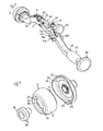
Figure 4 is an exploded perspective view of components of the prosthetic acetabular inserter and impactor as shown inFigure 1 ; -
Figure 5 is a cross-sectional side view of the portion of the prosthetic acetabular inserter and impactor as shown inFigure 1 , in said second in use configuration; and -
Figure 6 is a cross-sectional side view of the portion of the prosthetic acetabular inserter and impactor as shown inFigure 1 , in a third in use configuration. - As shown in
Figure 1 , a prosthetic acetabular cup inserter and impactor 1 comprises abody 2 and acup engaging element 3 disposed at afirst end 4 of saidbody 2 and adapted to engage aninner surface 5 of acup 6 with which it is used via outward biasing thereof. Thecup engaging element 3 increases in cross-sectional area from aninner end 7 thereof to a fullest transverse section, indicated by hashed line A-A, and decreases in cross-sectional area from said fullest transverse section A-A to anouter end 8 thereof. - The acetabular cup inserter and impactor 1 shown in the Figures is the same as that in the applicant's co-pending patent application referred to above, and it comprises several specialist features which are not relevant to the present invention, for example an axially rotating impaction plate, springs, locking teeth and so on. The present invention relates to the particular shape and operating principals of the
cup engaging element 3, and it will be appreciated that these could be applied to an acetabular cup inserter and impactor which does not include the above described specialist features. - Referring to the
cup engaging element 3, it is a resilient ring made from a suitable material, for example rubber or a plastics material, and it comprises anexterior surface 9 which is part-spherical. In particular, theexterior surface 9 has the characteristic of being spherical because all parts of thesurface 9 lie at substantially the same radius from acentre point 10. However, as is clear from the figures, the sphere is truncated by being delimited by two parallel planes, indicated inFigure 1 by lines B-B and C-C. - The
ring 3 comprises a central aperture 11 aligned on an axis D-D, which is normal to said parallel planes B-B and C-C. Taking the direction of D-D as a reference, theouter surface 9 of thering 3 increases in diameter from saidinner end 7, at plane B-B, to a fullest transverse section at plane A-A, and decreases in diameter from said fullest transverse section A-A to saidouter end 8, at plane C-C. - This basic structure is an essential feature of the present invention, and is designed to function with acetabular cups comprising particular characteristics, which are illustrated by
Figure 2. Figure 2 shows an enlarged section ofFigure 1 , and is compressed to half its original width in order to better illustrate the characteristics of theinner surface 5 of thecup 6. - In particular, the
inner surface 5 of thecup 6 comprises a part-sphericalinner bearing surface 12. Theinner bearing surface 12 has the characteristic of being spherical because all parts of it lie at the same radius from a centre point 13 (shown inFigure 1 ). As is clear fromFigure 2 , with thecup 6 axially aligned on axis D-D, theinner bearing surface 12 is slightly larger than a hemisphere. In particular, it comprises ahemispherical portion 14 which extends to plane E-E, and an additional portion 15 which extends to plane F-F. This greater than hemispherical shape is created during manufacture wheninner bearing surface 12 of thecup 6 is polished. - The
cup 6 also comprises aneck portion 16, which is cylindrical and extends from plane F-F to plane G-G. Therefore, theouter rim 17 of thecup 6 has a smaller diameter than the largest diameter of theinner bearing surface 12, at plane E-E. - The
outer rim 17 of thecup 6 is shaped to mimic the contours of the natural shape of an acetabulum, and is the same as that disclosed inEP1522283 . As referred to above, with this construction of cup theneck portion 16 is particularly short at the concave portions between the illium rim portion, the ischium rim portion and the pubis rim portion, and at the pubis rim portion itself. In fact, theneck 16 only really has any significant extent at the illium rim portion and the ischium rim portion. - Referring to
Figure 1 , the central aperture 11 has aninner surface 18 which tapers in a direction toward thefirst end 4 of thebody 2. Disposed inside the aperture 11 is a biasing means in the form ofcone element 19, which has anouter surface 20 having a taper corresponding with that of saidinner surface 18. Therefore, relative axial movement of thecone element 19 towards thefirst end 4 of thebody 2 in use causes thering 3 to be radially outwardly biased and/or expanded to engage thecup 6. - Referring to
Figure 4 , thering 3 comprises aslot 21 which extends axially from saidouter end 8 to saidinner end 7, and laterally from saidinner surface 18 to saidexterior surface 9. Thering 3 further comprises anaxially extending groove 22 formed in saidinner surface 18 opposite to saidslot 21. Thegroove 22 also extends from saidouter end 8 to saidinner end 7. These features allow thering 3 to be radially outwardly biased and/or expanded efficiently in use. - Referring back to
Figure 1 , animpaction plate 23 is disposed between thebody 2 and thering 3. Theimpaction plate 23 has afront face 24 against which theinner end 7 of thering 3 abuts. Thecone 19 moves towards saidfront face 24 when it is moved into the engaged position, and theimpaction plate 23 holds thering 3 axially in position when this happens, as described further below, ensuring that the axial movement of thecone 19 is converted into a radial outward biasing and/or expansion of thering 3. - The
impaction plate 23 also has annularcup engaging wall 25, which has an irregularupper surface 26 adapted to engage theouter rim 17 of thecup 6. - The central aperture 11 comprises a
first portion 27 which comprises the above described taper, and a secondnarrower portion 28 above saidfirst portion 27. Thecone element 19 comprises afirst portion 29 which comprises the above described taper, and asecond portion 30 above saidfirst portion 29, which tapers in the opposite direction. Thesecond portion 28 of the aperture 11 serves to retain thecone element 19 therein. It may also prevent thering 3 from moving axially towards thefront face 24 of theimpaction plate 23 when thecup 6 is initially applied to thering 4 in use, as described further below. Thesecond portion 28 of the aperture 11 engages thesecond portion 30 of thecone element 19, and significant axial compression of theresilient ring 3 is prevented. Thesecond portion 28 of the aperture 11 also assists in the dismantling of thecone element 19 and thering 3. When thecone element 19 is removed from the aperture 11, thesecond portion 30 of thecone element 19 engages thesecond portion 28 of the aperture 11 and forces theresilient ring 3 to expand, allowing thecone 19 to be freed. - The
resilient ring 3 also comprises arecess 31 formed in theinner end 7, which provides space for other components. - The prosthetic acetabular cup inserter and impactor 1 also comprises operating means, in the form of
rigid drive train 32, which is adapted to axially move thecone 19 relative to thering 3. Thedrive train 32 is carried by thebody 2, and comprises a number ofrods 33, held together withuniversal joints 34. As is clear fromFigure 3 , thebody 2 is curved, in the known way which is suitable for MIS, and thedrive train 32 is adapted to follow this curved shape. - The
cone 19 is connected to afirst end 35 of thedrive train 32. Aninner end rod 36 comprises acollar 37 and a screw threadedportion 38. Thecone 19 comprises a corresponding central aperture 39 provided with a screw thread, which is screwed onto to said screw threadedportion 38, such that anunderside 40 of thecone 19 abuts against saidcollar 37. - Referring to
Figure 3 , thedrive train 32 emerges from thebody 2 at anintermediary opening 41. An operatingknob 42 is provided at asecond end 43 of thedrive train 32. Movement of the operatingknob 42 towards thebody 2 moves thecone 19 from a preliminary position into an engaged position, as described further below. (Axial rotation of the operatingknob 42 is transmitted into axial rotation of thecone element 4 via axial rotation of therods 33 anduniversal joints 34 of thedrive train 32. However, this functionality is not of relevance to the present invention, so is not further described here in any detail.) - The
second end 43 of thedrive train 32 is supported by anadjustable housing 44, mounted on the end of arack 45. Therack 45 is disposed in aslot 46 in thebody 2, and is moveable therethrough both towards and away from thebody 2. The position of therack 45 is determined by a spring loaded ratchet (not visible) which is disposed inside thebody 2, and which extends laterally into saidslot 46 to engage thetoothed surface 47 of therack 45 and hold it in position. In an engaged position the ratchet is configured to allow therack 45 to ride over it when it is moved towards thebody 2, but to prevent therack 45 from moving away from thebody 2. In a disengaged position the ratchet allows therack 45 to move freely in theslot 46. Engagement and disengagement of the ratchet is controlled bylever 48. In the position shown inFigure 3 the ratchet is in the engaged position, and movement of thelever 48 away from thebody 2 disengages the ratchet. - Movement of the
rack 45 and thehousing 44 towards thebody 2 rotatesouter end rod 49 lengthwise about first pivot mounting 50.Outer end rod 49 is connected to intermediary rod 51 (visible inFigure 1 ) beyond the first pivot mounting 50, and therefore lengthwise rotation of theouter end rod 49 about first pivot mounting 50 rotates intermediary rod 51 lengthwise about its own second pivot mounting 52. Intermediary rod 51 is connected to inner end rod 36 (again visible inFigure 1 ) beyond said second pivot mounting 52, and therefore lengthwise rotation of the intermediary rod 51 about pivot mounting 52 axially moves theinner end rod 36 through asleeve 53 mounted between thebody 2 and theinner end rod 36. This draws thecone 19 towards theimpaction plate 23, which serves to outwardly bias and/or expand thering 3 to engage thecup 6. - Movement of the
rack 45 and thehousing 44 away from thebody 2 achieves the opposite result. Although in fact, when the ratchet is disengaged thering 3 is released from its outwardly biased state, and it contracts back to its neutral state, pushing thecone 19 back out, which in turn acts to move thedrive train 32 in the opposite manner to as described above, forcing therack 45,housing 44 and operatingknob 22 to move away from thebody 2. (When therack 45 is disengaged like this aspring 54 mounted between thebody 2 and theimpaction plate 23 acts to axially move theimpaction plate 23 on thesleeve 53. However, this axial movement of theimpaction plate 23 is once again functionally not of relevance to the present invention, so it is not further described here in any detail.) - It will be appreciated that the lengthwise rotation of intermediary rod 51 is not transmitted into a perfectly linear axial movement of
inner end rod 36, because the universal joint 34 therebetween follows an orbital path about pivot mounting 52. However, the required axial movement of theinner end rod 36 is short, and any deviation caused by the orbital movement of theuniversal joint 34 is well within functional tolerances. - The
body 2 had a handle 55 and animpaction anvil 56 at asecond end 57 thereof. The handle 55 facilitates the manipulation of thebody 2 in use, and theimpaction anvil 56 allows for an impaction force to be imparted to thecup 6 to fit it in the acetabulum in use. The longitudinal axes of thering 3 and said handle 55 are aligned so the impaction force is applied to thecup 6 in a linear fashion. Such a configuration is known, and is not further described here. - Referring to
Figure 4 , thecone 19 has a radially outwardly extendingspigot 58, and theimpaction plate 23 has a radially inwardly extendingspigot 59 provided on thecup engaging wall 25, both of which fit into theslot 21. These features facilitate the transmission of axial rotation of thecone 19 to theimpaction plate 23, which once again is a feature which is not relevant to the present invention, so is not further described here in any detail. - In use the inserter and impactor 1 operates as follows. Prior to engagement with the
cup 6, thecone element 19 is arranged in the preliminary position. This is achieved by placing the ratchet in its disengaged position, so thering 3 is not outwardly biased or expanded and holds thecone element 19 at an outer end of thefirst portion 27 of the central aperture 11. The ratchet is then engaged by movement of thelever 48 towards thebody 2, so that the operatingknob 42 will be held in position when later moved towards thebody 2 as described below. - As shown in
Figure 1 , the surgeon then introduces acup 6 to thering 3. With thecone 19 in the preliminary position as shown, thecup 6 can be forced onto thering 3 and held in place as shown inFigure 5 . As such, thecup 6 is partially engaged on thering 3, as it can be manually removed fairly easily if required. During this mounting process thesecond portion 28 of the aperture 11 may engage thesecond portion 30 of thecone 19 to prevent significant axial compression of theresilient ring 3. - It will be appreciated from
Figure 5 that because theexterior surface 9 of thering 3 increases in cross-sectional area from theinner end 7 to a fullest transverse section at plane A-A, and then decreases in cross-sectional area to theouter end 8, once the fullest transverse section of thering 3 has passed through theneck portion 16 of thecup 6, that section expands and engages theinner bearing surface 12 of thecup 6. As is clear fromFigure 5 , theexterior surface 9ring 3 is specifically shaped to mirror theinner bearing surface 12, so contact is made across most of theexterior surface 9 of thering 3. This provides a far larger contact area than would be achieved with a known conical or cylindrical ring, which would only engage theneck portion 16 of thecup 6. - Referring to
Figures 1 and 2 , it should be noted that a portion of thering 3 between the fullest transverse section at plane A-A and theinner end 7 engages the additional portion 15 of theinner bearing surface 12 between planes E-E and F-F. Not only does this increase the contact made between these surfaces, it also acts to hold thecup 6 in place on thering 3, in the manner of a snap-fit, because the fullest transverse section of thering 3 at plane A-A is wider than theneck portion 16 of thecup 6. - The
cup 6 is aligned with thecup engaging wall 25 such that the irregular shapes of theupper surface 26 of thewall 25 and therim 17 of thecup 6 fit together. - At this point the surgeon can axially rotate the
knob 42 to align thecup 6 andimpaction plate 23 as desired in relation to thebody 2. However, as mentioned above, this functionality is not relevant to the present invention, so is not further described here in any detail. - Once the
cup 6 is in place as shown inFigure 5 , the surgeon then pushes the operatingknob 42 downward towards thebody 2, as indicated byarrow 60 inFigure 3 , rotating theouter end rod 49 lengthwise in a clockwise direction about the first pivot mounting 50. As described above, this lengthwise rotational movement of theouter end rod 49 is transmitted to thecone element 19 via the lengthwise rotational movement of the intermediary rod 51 and the axial movement of theinner end rod 32, so thecone element 19 is axially moved a short distance towards theimpaction plate 23, to the position illustrated inFigure 6 . (In practice theimpaction plate 23 initially moves axially onsleeve 53 from the position shown inFigure 5 until it abuts against a collar component 55, against the force ofspring 54, as illustrated inFigure 6 . However, again this feature is not relevant to the present invention.) - In this engaged position the
ring 3 is radially outwardly biased, and is forced into greater contact with theinner bearing surface 12 of thecup 6, by virtue of the relative movement of the taperedcone 19 inside the tapered central aperture 11. This radial biasing compresses thering 3 against theinner bearing surface 12 of thecup 6, firmly fixing thecup 6 in a fully engaged position. In contrast to the partially engaged position shown inFigure 5 , thecup 6 cannot be readily manually removed from thering 3. - Downward movement of the operating
knob 42 towards thebody 2 forces therack 45 to ride over the ratchet until the engaged position is achieved, and then the ratchet locks thecone 19 in position. - Now the
cup 6 is fully engaged, the surgeon can introduce the inserter and impactor 1 into the patient and place thecup 6 in the acetabulum. They can then use a hammer or similar tool to impart an impaction force to theanvil 56 at thesecond end 57 of thebody 2, which acts to firmly locate thecup 6 in the acetabulum. - To release the
cup 6 from the inserter and impactor 1 thelever 48 is moved away from thebody 2 so therack 45 is disengaged. Thering 3 is then released from its outwardly biased state, contracts and returns to thecone 19 to the preliminary position. In this state thering 3 can be readily manually removed from thecup 7. - After surgery the inserter and impactor 1 can be dismantled for cleaning. The
ring 3 can be pulled from thecone 19 by virtue of its resilience. Thecone 19 can then be unscrewed from theinner end rod 32 and removed therefrom. - The above described embodiment can be altered without departing from the scope of claim 1. For example, in other alternative embodiments (not shown) inserter and impactors are provided which do not include the additional features forming a part of inserter and impactor 1 which are not relevant to the present invention. In particular, in one alternative embodiment (not shown), the impaction plate is statically mounted to the first end of the body, and the rigid drive train does not axially rotate the cone, the ring or the impaction plate in relation to the body. In another alternative embodiment (not shown) the body is straight, and the operating means is a straight rod which is axially moved in the body to actuate the cone. In other alternative embodiments (not shown), the body is either straight or curved, and the operating means is a flexible, tensionable cable.
- In other alternative embodiments (not shown) other types of biasing means are employed to outwardly bias the ring. For example, in one alternative embodiment (not shown) the resilient ring is drawn onto a static expander in a manner like that disclosed in
W02009136284 . In another alternative embodiment (not shown) the outer end of the ring is depressed by an overlying expander means in a manner like that disclosed inEP15708145 US2004/0215200 . - In another alternative embodiment (not shown), the resilient ring is a snap-fit onto the front face of the impaction plate. The ring can be slightly larger than the inner diameter of the cup engaging wall, so it is retained within it.
- In another alternative embodiment (not shown) the cone is releasably fixed to the first end of the drive train with a spring loaded quick release mechanism. This allows for the inserter and impactor to be more readily dismantled.
- Thus, the present invention provides a cup engaging ring with a shape which allows it to properly and effectively engage a cup with an inner bearing surface which is greater than hemi-spherical in shape and with a neck portion of very limited extent.
Claims (20)
- A prosthetic acetabular cup inserter and impactor comprising a body, and a cup engaging element disposed at a first end of said body and adapted to engage an inner surface of a cup with which it is used via outward biasing thereof, in which said cup engaging element increases in cross-sectional area from an inner end thereof to a fullest transverse section, and decreases in cross-sectional area from said fullest transverse section to an outer end thereof.
- A prosthetic acetabular cup inserter and impactor as claimed in claim 1, in which said cup engaging element comprises an exterior surface which is part-spherical, and which increases in diameter from said inner end to said fullest transverse section, and decreases in diameter from said fullest transverse section to said outer end.
- A prosthetic acetabular cup inserter and impactor as claimed in claim 2 further comprising biasing means adapted to bias said cup engaging element outwardly via relative axial movement therewith, and operating means adapted to axially move said biasing means relative to said cup engaging element.
- A prosthetic acetabular cup inserter and impactor as claimed in claim 3 in which said cup engaging element comprises a resilient ring comprising a central aperture having an inner surface which tapers in a direction toward said first end of said body, and in which said biasing means comprises a cone element disposed within said aperture and which comprises an outer surface having a taper corresponding with that of said inner surface.
- A prosthetic acetabular cup inserter and impactor as claimed in claim 4 in which said operating means axially moves said cone element from a preliminary position into an engaged position, in which in said engaged position said cup is fully engaged with said cup engaging element.
- A prosthetic acetabular cup inserter and impactor as claimed in claim 5 in which in said preliminary position said cup is partially engaged with said cup engaging element.
- A prosthetic acetabular cup inserter and impactor as claimed claim 6 in which a plate is disposed between said first end of said body and said cup engaging element, in which said plate comprises a front face against which said inner end of said cup engaging element abuts, and in which said biasing means moves towards said front face when it is moved into said engaged position.
- A prosthetic acetabular cup inserter and impactor as claimed in claim 4 in which said resilient ring comprises a slot which extends axially from said outer end to said inner end, and laterally from said inner surface of said exterior surface.
- A prosthetic acetabular cup inserter and impactor as claimed in claim 8 in which said resilient ring further comprises an axially extending groove formed in said inner surface opposite to said slot.
- A prosthetic acetabular cup inserter and impactor as claimed in claim 7 in which said plate comprises an impaction plate having an annular cup engaging wall adapted to engage a rim of said cup.
- A prosthetic acetabular cup inserter and impactor as claimed in claim 10 in which said annular cup engaging wall comprises an irregular upper surface comprising a plurality of convex portions.
- A prosthetic acetabular cup inserter and impactor as claimed in claim 5 in which said operating means comprises a rigid drive train carried by said body and comprising a connection to said biasing means at a first end thereof, and an operating knob at a second end thereof, which operating knob is operable to axially move said biasing means from said preliminary position into said engaged position.
- A prosthetic acetabular cup inserter and impactor as claimed in claim 12 in which said second end of said rigid drive train is carried on a rack, in which said rack is disposed in a slot in said body, and is moveable therethrough both towards and away from said body, in which the position of said rack is determined by a spring loaded ratchet disposed inside said body, and which extends laterally into said slot to engage said rack, in which said ratchet is movable between an engaged position and a disengaged position, in which in said engaged position said ratchet allows said rack to ride over it when said rack is moved towards said body and prevents said rack from moving away from said body, in which in said disengaged position said ratchet allows said rack to move freely in said slot, in which movement of said second end of said rigid drive train towards said body is converted by the rigid drive train into axial movement of said biasing means into said engaged position.
- A prosthetic acetabular cup inserter and impactor as claimed in claim 13 in which said body is curved and in which said rigid drive train comprises an outer end rod, an intermediary rod and an inner end rod, connected together end to end in sequence by universal joints, in which said outer end rod is mounted part way along its length in a first pivot mounting, in which said intermediary rod is mounted part way along its length in a second pivot mounting, in which said inner rod is mounted for axial movement in a sleeve mounted at a first end of said body, in which movement of said second end of said rigid drive train towards said body rotates said outer end rod lengthwise about said first pivot mounting in a first direction, which rotates said intermediary rod lengthwise about said second pivot mounting in a second direction, which moves said inner rod substantially axially through said sleeve.
- A prosthetic acetabular cup inserter and impactor as claimed in claim 12 in which said biasing means is releasably fixed to said first end of said drive train with a screw thread.
- A prosthetic acetabular cup inserter and impactor as claimed in claim 12 in which said biasing means is releasably fixed to said first end of said drive train with a spring loaded quick release mechanism.
- A prosthetic acetabular cup inserter and impactor as claimed in claim 10 in which said impaction plate is mounted to said first end of said body with a spring loaded quick release mechanism.
- A prosthetic acetabular cup inserter and impactor as claimed in claim 10 in which said cup engaging element is a snap-fit onto said front face.
- A prosthetic acetabular cup inserter and impactor as claimed in any of the preceding claims in which a second end of said body is provided with a handle and an impaction anvil or plate.
- A prosthetic acetabular cup inserter and impactor as claimed in claim 19 in which said body is curved, and in which longitudinal axes of said cup engaging means and said handle are substantially aligned.
Applications Claiming Priority (1)
| Application Number | Priority Date | Filing Date | Title |
|---|---|---|---|
| GB201020041A GB201020041D0 (en) | 2010-11-25 | 2010-11-25 | Prosthetic acetabular cup inserter and impactor |
Publications (2)
| Publication Number | Publication Date |
|---|---|
| EP2457543A1 true EP2457543A1 (en) | 2012-05-30 |
| EP2457543B1 EP2457543B1 (en) | 2017-04-05 |
Family
ID=43500662
Family Applications (1)
| Application Number | Title | Priority Date | Filing Date |
|---|---|---|---|
| EP11250902.1A Active EP2457543B1 (en) | 2010-11-25 | 2011-11-18 | Prosthetic acetabular cup inserter and impactor |
Country Status (4)
| Country | Link |
|---|---|
| US (1) | US8834479B2 (en) |
| EP (1) | EP2457543B1 (en) |
| AU (1) | AU2011253603B2 (en) |
| GB (1) | GB201020041D0 (en) |
Cited By (2)
| Publication number | Priority date | Publication date | Assignee | Title |
|---|---|---|---|---|
| EP2684543A1 (en) * | 2012-07-10 | 2014-01-15 | Stryker Ireland Limited | Prosthetic acetabular cup impaction plate |
| FR3034005A1 (en) * | 2015-03-23 | 2016-09-30 | Fournitures Hospitalieres Ind | BODY FOR HOLDING A COTYLOID IMPLANT CUP |
Families Citing this family (8)
| Publication number | Priority date | Publication date | Assignee | Title |
|---|---|---|---|---|
| FR2994645B1 (en) * | 2012-08-21 | 2014-08-22 | Rech S Et De Fabrication Serf Soc Et | ANCILLARY FOR THE IMPLANTATION OF A CUPULE, IN PARTICULAR A COTYLOID IMPLANT |
| US10568649B2 (en) | 2014-05-06 | 2020-02-25 | Howmedica Osteonics Corp. | Acetabular reamer |
| EP3111897B1 (en) | 2015-07-02 | 2018-11-14 | Greatbatch Ltd. | Orthopedic impactor |
| US10603178B2 (en) | 2016-11-22 | 2020-03-31 | Storage Enterprises, LLC | Prosthetic hip system |
| CN109381281B (en) * | 2017-08-07 | 2024-02-13 | 创生医疗器械(中国)有限公司 | Acetabular system and method of using the same |
| WO2019057867A1 (en) * | 2017-09-22 | 2019-03-28 | Medichanical Engineering Aps | Device for radial expansion of an acetabulum measuring head |
| GB2585284B (en) | 2018-02-27 | 2022-07-13 | Nextremity Solutions Inc | Disposable handle for medical instruments |
| US12064356B2 (en) | 2021-08-19 | 2024-08-20 | Howmedica Osteonics Corp. | Multi-size acetabular impactor |
Citations (10)
| Publication number | Priority date | Publication date | Assignee | Title |
|---|---|---|---|---|
| FR2701206A1 (en) * | 1993-02-09 | 1994-08-12 | Medinov Sa | Impacter equipment for a polyethylene core or cup for acetabular implant |
| US20040215200A1 (en) | 2003-01-17 | 2004-10-28 | Alain Tornier | Ancillary tool and method for positioning a prosthetic acetabulum of a hip prosthesis |
| EP1522283A2 (en) | 2003-09-15 | 2005-04-13 | Benoist Girard Sas | Prosthetic acetabular cup and prosthetic femoral joint incorporating such a cup |
| EP1570815A1 (en) | 2004-03-05 | 2005-09-07 | Benoist Girard SAS | Prosthetic acetabular cup inserter |
| US20060149285A1 (en) * | 2004-12-09 | 2006-07-06 | Precimed S.A. | Inserter for minimally invasive joint surgery |
| EP1813229A1 (en) | 2006-01-25 | 2007-08-01 | Symmetry Medical, Inc. | Split thread orthopaedic implant impactor |
| US20070270783A1 (en) | 2004-06-22 | 2007-11-22 | Lukas Zumsteg | Device for Placing or Removing Joints or Joints Sockets |
| US20080021481A1 (en) | 2006-05-01 | 2008-01-24 | Precimed S.A. | Inserter for minimally invasive joint surgery having interchangeable thread |
| WO2009136284A1 (en) | 2008-05-07 | 2009-11-12 | Benoist Girard Sas | Prosthetic acetabular cup inserter and impactor |
| FR2948013A1 (en) * | 2009-07-16 | 2011-01-21 | Rech S Et De Fabrication Serf Soc Et | Metal cup for ancillary during cotyloidal implant of total hip prosthesis of patient, has restricted section provided at free edge of part with respect to section of part at equatorial plane to form undercut |
Family Cites Families (7)
| Publication number | Priority date | Publication date | Assignee | Title |
|---|---|---|---|---|
| US5098437A (en) | 1991-02-13 | 1992-03-24 | Pfizer Hospital Products Group, Inc. | Acetabular cup positioning insert |
| US5171243A (en) | 1991-02-13 | 1992-12-15 | Pfizer Hospital Products Group, Inc. | Acetabular cup positioning insert |
| US5169399A (en) * | 1991-10-17 | 1992-12-08 | Boehringer Mannheim Corporation | Acetabular cup impactor |
| US5954727A (en) | 1993-10-29 | 1999-09-21 | Howmedica Inc. | Acetabular cup positioning tool and method of positioning an acetabular cup |
| GB0426385D0 (en) | 2004-12-01 | 2005-01-05 | Benoist Girard Sas | Prosthetic implanatation inserter for a flexible acetabular cup |
| US7993348B2 (en) | 2005-12-20 | 2011-08-09 | Howmedica Osteonics Corp. | Curved acetabular positioner, impactor and reamer handle |
| US8430886B2 (en) | 2010-01-25 | 2013-04-30 | Howmedica Osteonics Corp. | Inserter for locating and impacting an acetabular cup |
-
2010
- 2010-11-25 GB GB201020041A patent/GB201020041D0/en not_active Ceased
-
2011
- 2011-11-18 EP EP11250902.1A patent/EP2457543B1/en active Active
- 2011-11-22 US US13/302,376 patent/US8834479B2/en active Active
- 2011-11-22 AU AU2011253603A patent/AU2011253603B2/en active Active
Patent Citations (10)
| Publication number | Priority date | Publication date | Assignee | Title |
|---|---|---|---|---|
| FR2701206A1 (en) * | 1993-02-09 | 1994-08-12 | Medinov Sa | Impacter equipment for a polyethylene core or cup for acetabular implant |
| US20040215200A1 (en) | 2003-01-17 | 2004-10-28 | Alain Tornier | Ancillary tool and method for positioning a prosthetic acetabulum of a hip prosthesis |
| EP1522283A2 (en) | 2003-09-15 | 2005-04-13 | Benoist Girard Sas | Prosthetic acetabular cup and prosthetic femoral joint incorporating such a cup |
| EP1570815A1 (en) | 2004-03-05 | 2005-09-07 | Benoist Girard SAS | Prosthetic acetabular cup inserter |
| US20070270783A1 (en) | 2004-06-22 | 2007-11-22 | Lukas Zumsteg | Device for Placing or Removing Joints or Joints Sockets |
| US20060149285A1 (en) * | 2004-12-09 | 2006-07-06 | Precimed S.A. | Inserter for minimally invasive joint surgery |
| EP1813229A1 (en) | 2006-01-25 | 2007-08-01 | Symmetry Medical, Inc. | Split thread orthopaedic implant impactor |
| US20080021481A1 (en) | 2006-05-01 | 2008-01-24 | Precimed S.A. | Inserter for minimally invasive joint surgery having interchangeable thread |
| WO2009136284A1 (en) | 2008-05-07 | 2009-11-12 | Benoist Girard Sas | Prosthetic acetabular cup inserter and impactor |
| FR2948013A1 (en) * | 2009-07-16 | 2011-01-21 | Rech S Et De Fabrication Serf Soc Et | Metal cup for ancillary during cotyloidal implant of total hip prosthesis of patient, has restricted section provided at free edge of part with respect to section of part at equatorial plane to form undercut |
Cited By (2)
| Publication number | Priority date | Publication date | Assignee | Title |
|---|---|---|---|---|
| EP2684543A1 (en) * | 2012-07-10 | 2014-01-15 | Stryker Ireland Limited | Prosthetic acetabular cup impaction plate |
| FR3034005A1 (en) * | 2015-03-23 | 2016-09-30 | Fournitures Hospitalieres Ind | BODY FOR HOLDING A COTYLOID IMPLANT CUP |
Also Published As
| Publication number | Publication date |
|---|---|
| GB201020041D0 (en) | 2011-01-12 |
| EP2457543B1 (en) | 2017-04-05 |
| AU2011253603B2 (en) | 2016-11-24 |
| AU2011253603A1 (en) | 2012-06-14 |
| US20120136360A1 (en) | 2012-05-31 |
| US8834479B2 (en) | 2014-09-16 |
Similar Documents
| Publication | Publication Date | Title |
|---|---|---|
| EP2457543B1 (en) | Prosthetic acetabular cup inserter and impactor | |
| EP2457542B1 (en) | Prosthetic acetabular cup inserter and impactor | |
| US7341593B2 (en) | Prosthetic acetabular cup inserter | |
| US4100626A (en) | Wrist implant apparatus | |
| US10166118B2 (en) | Spiral assembly tool | |
| US5540697A (en) | Prosthetic socket installation apparatus and method | |
| US8821503B2 (en) | Ancillary tool and method for positioning a prosthetic acetabulum of a hip prosthesis | |
| US7785331B2 (en) | Acetabular liner extraction device, kit and associated method | |
| US20070005144A1 (en) | Expandable acetabular liner extraction device, cup assembly and associated method | |
| JP4034378B2 (en) | Alternative femoral head adapter, alternative femoral head system and alternative femoral head | |
| US20060149285A1 (en) | Inserter for minimally invasive joint surgery | |
| WO2003084432A2 (en) | Liner assembly for prosthetic components | |
| EP1679051B1 (en) | Trial bearing insert | |
| WO2015044680A1 (en) | An instrument for positioning a cup component of an orthopaedic joint prosthesis | |
| JP2019514537A (en) | Impactor | |
| JP4215867B2 (en) | Bipolar-unipolar type femoral head adapter | |
| EP2737877B1 (en) | Orthopaedic prosthesis assembly tool | |
| EP2663261B1 (en) | A socket, in particular an acetabular socket for a hip endoprosthesis |
Legal Events
| Date | Code | Title | Description |
|---|---|---|---|
| PUAI | Public reference made under article 153(3) epc to a published international application that has entered the european phase |
Free format text: ORIGINAL CODE: 0009012 |
|
| AK | Designated contracting states |
Kind code of ref document: A1 Designated state(s): AL AT BE BG CH CY CZ DE DK EE ES FI FR GB GR HR HU IE IS IT LI LT LU LV MC MK MT NL NO PL PT RO RS SE SI SK SM TR |
|
| AX | Request for extension of the european patent |
Extension state: BA ME |
|
| 17P | Request for examination filed |
Effective date: 20121129 |
|
| RAP1 | Party data changed (applicant data changed or rights of an application transferred) |
Owner name: STRYKER IRELAND LIMITED |
|
| 17Q | First examination report despatched |
Effective date: 20150922 |
|
| RAP1 | Party data changed (applicant data changed or rights of an application transferred) |
Owner name: STRYKER EUROPEAN HOLDINGS I, LLC |
|
| GRAP | Despatch of communication of intention to grant a patent |
Free format text: ORIGINAL CODE: EPIDOSNIGR1 |
|
| STAA | Information on the status of an ep patent application or granted ep patent |
Free format text: STATUS: GRANT OF PATENT IS INTENDED |
|
| INTG | Intention to grant announced |
Effective date: 20161202 |
|
| GRAS | Grant fee paid |
Free format text: ORIGINAL CODE: EPIDOSNIGR3 |
|
| GRAA | (expected) grant |
Free format text: ORIGINAL CODE: 0009210 |
|
| STAA | Information on the status of an ep patent application or granted ep patent |
Free format text: STATUS: THE PATENT HAS BEEN GRANTED |
|
| AK | Designated contracting states |
Kind code of ref document: B1 Designated state(s): AL AT BE BG CH CY CZ DE DK EE ES FI FR GB GR HR HU IE IS IT LI LT LU LV MC MK MT NL NO PL PT RO RS SE SI SK SM TR |
|
| REG | Reference to a national code |
Ref country code: GB Ref legal event code: FG4D |
|
| REG | Reference to a national code |
Ref country code: CH Ref legal event code: EP |
|
| REG | Reference to a national code |
Ref country code: AT Ref legal event code: REF Ref document number: 881080 Country of ref document: AT Kind code of ref document: T Effective date: 20170415 |
|
| REG | Reference to a national code |
Ref country code: IE Ref legal event code: FG4D |
|
| REG | Reference to a national code |
Ref country code: DE Ref legal event code: R096 Ref document number: 602011036624 Country of ref document: DE |
|
| REG | Reference to a national code |
Ref country code: NL Ref legal event code: MP Effective date: 20170405 |
|
| REG | Reference to a national code |
Ref country code: LT Ref legal event code: MG4D |
|
| REG | Reference to a national code |
Ref country code: AT Ref legal event code: MK05 Ref document number: 881080 Country of ref document: AT Kind code of ref document: T Effective date: 20170405 |
|
| PG25 | Lapsed in a contracting state [announced via postgrant information from national office to epo] |
Ref country code: NL Free format text: LAPSE BECAUSE OF FAILURE TO SUBMIT A TRANSLATION OF THE DESCRIPTION OR TO PAY THE FEE WITHIN THE PRESCRIBED TIME-LIMIT Effective date: 20170405 |
|
| REG | Reference to a national code |
Ref country code: FR Ref legal event code: PLFP Year of fee payment: 7 |
|
| PG25 | Lapsed in a contracting state [announced via postgrant information from national office to epo] |
Ref country code: NO Free format text: LAPSE BECAUSE OF FAILURE TO SUBMIT A TRANSLATION OF THE DESCRIPTION OR TO PAY THE FEE WITHIN THE PRESCRIBED TIME-LIMIT Effective date: 20170705 Ref country code: LT Free format text: LAPSE BECAUSE OF FAILURE TO SUBMIT A TRANSLATION OF THE DESCRIPTION OR TO PAY THE FEE WITHIN THE PRESCRIBED TIME-LIMIT Effective date: 20170405 Ref country code: GR Free format text: LAPSE BECAUSE OF FAILURE TO SUBMIT A TRANSLATION OF THE DESCRIPTION OR TO PAY THE FEE WITHIN THE PRESCRIBED TIME-LIMIT Effective date: 20170706 Ref country code: HR Free format text: LAPSE BECAUSE OF FAILURE TO SUBMIT A TRANSLATION OF THE DESCRIPTION OR TO PAY THE FEE WITHIN THE PRESCRIBED TIME-LIMIT Effective date: 20170405 Ref country code: ES Free format text: LAPSE BECAUSE OF FAILURE TO SUBMIT A TRANSLATION OF THE DESCRIPTION OR TO PAY THE FEE WITHIN THE PRESCRIBED TIME-LIMIT Effective date: 20170405 Ref country code: AT Free format text: LAPSE BECAUSE OF FAILURE TO SUBMIT A TRANSLATION OF THE DESCRIPTION OR TO PAY THE FEE WITHIN THE PRESCRIBED TIME-LIMIT Effective date: 20170405 Ref country code: FI Free format text: LAPSE BECAUSE OF FAILURE TO SUBMIT A TRANSLATION OF THE DESCRIPTION OR TO PAY THE FEE WITHIN THE PRESCRIBED TIME-LIMIT Effective date: 20170405 |
|
| PG25 | Lapsed in a contracting state [announced via postgrant information from national office to epo] |
Ref country code: IS Free format text: LAPSE BECAUSE OF FAILURE TO SUBMIT A TRANSLATION OF THE DESCRIPTION OR TO PAY THE FEE WITHIN THE PRESCRIBED TIME-LIMIT Effective date: 20170805 Ref country code: LV Free format text: LAPSE BECAUSE OF FAILURE TO SUBMIT A TRANSLATION OF THE DESCRIPTION OR TO PAY THE FEE WITHIN THE PRESCRIBED TIME-LIMIT Effective date: 20170405 Ref country code: SE Free format text: LAPSE BECAUSE OF FAILURE TO SUBMIT A TRANSLATION OF THE DESCRIPTION OR TO PAY THE FEE WITHIN THE PRESCRIBED TIME-LIMIT Effective date: 20170405 Ref country code: BG Free format text: LAPSE BECAUSE OF FAILURE TO SUBMIT A TRANSLATION OF THE DESCRIPTION OR TO PAY THE FEE WITHIN THE PRESCRIBED TIME-LIMIT Effective date: 20170705 Ref country code: PL Free format text: LAPSE BECAUSE OF FAILURE TO SUBMIT A TRANSLATION OF THE DESCRIPTION OR TO PAY THE FEE WITHIN THE PRESCRIBED TIME-LIMIT Effective date: 20170405 Ref country code: RS Free format text: LAPSE BECAUSE OF FAILURE TO SUBMIT A TRANSLATION OF THE DESCRIPTION OR TO PAY THE FEE WITHIN THE PRESCRIBED TIME-LIMIT Effective date: 20170405 |
|
| REG | Reference to a national code |
Ref country code: DE Ref legal event code: R097 Ref document number: 602011036624 Country of ref document: DE |
|
| PG25 | Lapsed in a contracting state [announced via postgrant information from national office to epo] |
Ref country code: CZ Free format text: LAPSE BECAUSE OF FAILURE TO SUBMIT A TRANSLATION OF THE DESCRIPTION OR TO PAY THE FEE WITHIN THE PRESCRIBED TIME-LIMIT Effective date: 20170405 Ref country code: EE Free format text: LAPSE BECAUSE OF FAILURE TO SUBMIT A TRANSLATION OF THE DESCRIPTION OR TO PAY THE FEE WITHIN THE PRESCRIBED TIME-LIMIT Effective date: 20170405 Ref country code: SK Free format text: LAPSE BECAUSE OF FAILURE TO SUBMIT A TRANSLATION OF THE DESCRIPTION OR TO PAY THE FEE WITHIN THE PRESCRIBED TIME-LIMIT Effective date: 20170405 Ref country code: RO Free format text: LAPSE BECAUSE OF FAILURE TO SUBMIT A TRANSLATION OF THE DESCRIPTION OR TO PAY THE FEE WITHIN THE PRESCRIBED TIME-LIMIT Effective date: 20170405 Ref country code: DK Free format text: LAPSE BECAUSE OF FAILURE TO SUBMIT A TRANSLATION OF THE DESCRIPTION OR TO PAY THE FEE WITHIN THE PRESCRIBED TIME-LIMIT Effective date: 20170405 |
|
| PLBE | No opposition filed within time limit |
Free format text: ORIGINAL CODE: 0009261 |
|
| STAA | Information on the status of an ep patent application or granted ep patent |
Free format text: STATUS: NO OPPOSITION FILED WITHIN TIME LIMIT |
|
| PG25 | Lapsed in a contracting state [announced via postgrant information from national office to epo] |
Ref country code: SM Free format text: LAPSE BECAUSE OF FAILURE TO SUBMIT A TRANSLATION OF THE DESCRIPTION OR TO PAY THE FEE WITHIN THE PRESCRIBED TIME-LIMIT Effective date: 20170405 Ref country code: IT Free format text: LAPSE BECAUSE OF FAILURE TO SUBMIT A TRANSLATION OF THE DESCRIPTION OR TO PAY THE FEE WITHIN THE PRESCRIBED TIME-LIMIT Effective date: 20170405 |
|
| 26N | No opposition filed |
Effective date: 20180108 |
|
| PG25 | Lapsed in a contracting state [announced via postgrant information from national office to epo] |
Ref country code: SI Free format text: LAPSE BECAUSE OF FAILURE TO SUBMIT A TRANSLATION OF THE DESCRIPTION OR TO PAY THE FEE WITHIN THE PRESCRIBED TIME-LIMIT Effective date: 20170405 |
|
| PG25 | Lapsed in a contracting state [announced via postgrant information from national office to epo] |
Ref country code: MC Free format text: LAPSE BECAUSE OF FAILURE TO SUBMIT A TRANSLATION OF THE DESCRIPTION OR TO PAY THE FEE WITHIN THE PRESCRIBED TIME-LIMIT Effective date: 20170405 |
|
| PG25 | Lapsed in a contracting state [announced via postgrant information from national office to epo] |
Ref country code: LI Free format text: LAPSE BECAUSE OF NON-PAYMENT OF DUE FEES Effective date: 20171130 Ref country code: CH Free format text: LAPSE BECAUSE OF NON-PAYMENT OF DUE FEES Effective date: 20171130 |
|
| PG25 | Lapsed in a contracting state [announced via postgrant information from national office to epo] |
Ref country code: LU Free format text: LAPSE BECAUSE OF NON-PAYMENT OF DUE FEES Effective date: 20171118 |
|
| REG | Reference to a national code |
Ref country code: BE Ref legal event code: MM Effective date: 20171130 |
|
| REG | Reference to a national code |
Ref country code: IE Ref legal event code: MM4A |
|
| PG25 | Lapsed in a contracting state [announced via postgrant information from national office to epo] |
Ref country code: MT Free format text: LAPSE BECAUSE OF NON-PAYMENT OF DUE FEES Effective date: 20171118 |
|
| REG | Reference to a national code |
Ref country code: FR Ref legal event code: PLFP Year of fee payment: 8 |
|
| PG25 | Lapsed in a contracting state [announced via postgrant information from national office to epo] |
Ref country code: IE Free format text: LAPSE BECAUSE OF NON-PAYMENT OF DUE FEES Effective date: 20171118 |
|
| PG25 | Lapsed in a contracting state [announced via postgrant information from national office to epo] |
Ref country code: BE Free format text: LAPSE BECAUSE OF NON-PAYMENT OF DUE FEES Effective date: 20171130 |
|
| PG25 | Lapsed in a contracting state [announced via postgrant information from national office to epo] |
Ref country code: HU Free format text: LAPSE BECAUSE OF FAILURE TO SUBMIT A TRANSLATION OF THE DESCRIPTION OR TO PAY THE FEE WITHIN THE PRESCRIBED TIME-LIMIT; INVALID AB INITIO Effective date: 20111118 |
|
| PG25 | Lapsed in a contracting state [announced via postgrant information from national office to epo] |
Ref country code: CY Free format text: LAPSE BECAUSE OF NON-PAYMENT OF DUE FEES Effective date: 20170405 |
|
| PG25 | Lapsed in a contracting state [announced via postgrant information from national office to epo] |
Ref country code: MK Free format text: LAPSE BECAUSE OF FAILURE TO SUBMIT A TRANSLATION OF THE DESCRIPTION OR TO PAY THE FEE WITHIN THE PRESCRIBED TIME-LIMIT Effective date: 20170405 |
|
| PG25 | Lapsed in a contracting state [announced via postgrant information from national office to epo] |
Ref country code: TR Free format text: LAPSE BECAUSE OF FAILURE TO SUBMIT A TRANSLATION OF THE DESCRIPTION OR TO PAY THE FEE WITHIN THE PRESCRIBED TIME-LIMIT Effective date: 20170405 |
|
| PG25 | Lapsed in a contracting state [announced via postgrant information from national office to epo] |
Ref country code: PT Free format text: LAPSE BECAUSE OF FAILURE TO SUBMIT A TRANSLATION OF THE DESCRIPTION OR TO PAY THE FEE WITHIN THE PRESCRIBED TIME-LIMIT Effective date: 20170405 |
|
| PG25 | Lapsed in a contracting state [announced via postgrant information from national office to epo] |
Ref country code: AL Free format text: LAPSE BECAUSE OF FAILURE TO SUBMIT A TRANSLATION OF THE DESCRIPTION OR TO PAY THE FEE WITHIN THE PRESCRIBED TIME-LIMIT Effective date: 20170405 |
|
| REG | Reference to a national code |
Ref country code: DE Ref legal event code: R082 Ref document number: 602011036624 Country of ref document: DE Representative=s name: LEDERER & KELLER PATENTANWAELTE PARTNERSCHAFT , DE Ref country code: DE Ref legal event code: R081 Ref document number: 602011036624 Country of ref document: DE Owner name: STRYKER EUROPEAN OPERATIONS HOLDINGS LLC, KALA, US Free format text: FORMER OWNER: STRYKER EUROPEAN HOLDINGS I, LLC, KALAMAZOO, MICH., US |
|
| REG | Reference to a national code |
Ref country code: GB Ref legal event code: 732E Free format text: REGISTERED BETWEEN 20210408 AND 20210414 |
|
| P01 | Opt-out of the competence of the unified patent court (upc) registered |
Effective date: 20230522 |
|
| REG | Reference to a national code |
Ref country code: DE Ref legal event code: R082 Ref document number: 602011036624 Country of ref document: DE Representative=s name: KRAUS & LEDERER PARTGMBB, DE |
|
| PGFP | Annual fee paid to national office [announced via postgrant information from national office to epo] |
Ref country code: GB Payment date: 20250925 Year of fee payment: 15 |
|
| PGFP | Annual fee paid to national office [announced via postgrant information from national office to epo] |
Ref country code: FR Payment date: 20250908 Year of fee payment: 15 |
|
| PGFP | Annual fee paid to national office [announced via postgrant information from national office to epo] |
Ref country code: DE Payment date: 20250923 Year of fee payment: 15 |