EP2457072B1 - Shack hartman sensor with removable lenslet array - Google Patents
Shack hartman sensor with removable lenslet array Download PDFInfo
- Publication number
- EP2457072B1 EP2457072B1 EP10739756.4A EP10739756A EP2457072B1 EP 2457072 B1 EP2457072 B1 EP 2457072B1 EP 10739756 A EP10739756 A EP 10739756A EP 2457072 B1 EP2457072 B1 EP 2457072B1
- Authority
- EP
- European Patent Office
- Prior art keywords
- optical
- sensor
- wave front
- dissector
- dowel pin
- Prior art date
- Legal status (The legal status is an assumption and is not a legal conclusion. Google has not performed a legal analysis and makes no representation as to the accuracy of the status listed.)
- Active
Links
Images


Classifications
-
- G—PHYSICS
- G01—MEASURING; TESTING
- G01J—MEASUREMENT OF INTENSITY, VELOCITY, SPECTRAL CONTENT, POLARISATION, PHASE OR PULSE CHARACTERISTICS OF INFRARED, VISIBLE OR ULTRAVIOLET LIGHT; COLORIMETRY; RADIATION PYROMETRY
- G01J9/00—Measuring optical phase difference; Determining degree of coherence; Measuring optical wavelength
Definitions
- the present invention relates to sensors in general, and more particularly to a Shack Hartmann ("SH") Wavefront Sensor with a removable lenslet array. More particularly, this invention relates to means of removably and replaceably mounting a wave front dissector relative to a sensor such that the dissector is not permanently fixed in position relative to the sensor while maintaining precise relative alignment between the dissector and sensor, such that the precision and accuracy of the measured wave front for the combined dissector and sensor is not degraded relative to wave front sensors that permanently fix the dissector relative to the sensor.
- SH Shack Hartmann
- a body in free space has six independent degrees of freedom, three translational, and three rotational, all typically defined with respect to a Cartesian coordinate system with the three translational degrees of freedom taking place along the three perpendicular axis of the Cartesian coordinate system, and the three angular degrees of freedom being defined as rotational degrees of freedom about the axis of the same system.
- the motion of a body in space can be described as a linear combination of these coordinates.
- each degree of freedom can be restrained with the appropriate placement of a point restraint on the body.
- a nearly ideal point restraint can be achieved using a high quality hardened steel ball bearing pressing against a polished sapphire plate that is optically flat (better than 0.25 microns) that is attached to the body being constrained.
- kinematical design Within the field of opto-mechanical design the concept of a "kinematical design" is well known, here the designer is challenged to provide just one nearly ideal constraint for each of the six degrees of freedom that a body has in free space. Additionally a successful kinematic design is typically considered to be relatively independent of the structure being built but relies on the use of inexpensive mass produced parts such as precision hardened steel ball bearings and small optically polished sapphire plates to form a kinematic interface between moving or joined parts.
- the book “Building Scientific Apparatus” by John H. Moore et al describes the details of achieving a reasonable approximation to a kinematic design, see for example page 43 sections 1.6.1 and 1.6.2 of the 3rd addition.
- This KB3X3 device is advertised as providing micro-radian level repeatability in its rotational degrees of freedom after repeated removal and replacement of the top of the two part device. It is assumed that the bottom part of the device is securely fixed to a massively rigid structure, typically an optical table also sold by Thorlabs. The typical use of the Thorlabs device is to allow the user to build flexible optical systems with one use being the redirecting of a laser beam on an optical table from one experimental setup to another with a high degree of repeatability. To achieve this function a KB3X3 in located along the laser beam path, for this example assume an existing experiment lies a small distance in front of the source of the laser beam.
- a kinematic mirror mount for example a Thorlabs KS1 along with an appropriate mirror
- the mirror is mounted to the top plate of the KB3X3 using opto-mechanical holders well known within the field of optical sciences and also provided by Thorlabs.
- the mirror mount controls to deflect the beam well away from the uninterrupted beam path to an unused portion of the optical table.
- the user can have the laser available for two experiments, by placing the top plate of the KB3X3 onto its base the beam is deflected precisely along the desired path to the unused portion of the optical table where a second experiment can be constructed. And by removing the top plate of the KB3X3 the undeflected beam is free to travel past the KB3X3 to serve the first application.
- SH Wavefront Sensors are capable of accurate measurements of an optical wave front's shape and intensity distribution by analyzing the location and intensity of spots (spot field) formed by imaging an incident light field onto a CCD (charge coupled device) camera, for example, via a lenslet array or a micro-lens array.
- CCD charge coupled device
- the lenslet array must be very precisely aligned relative to the CCD sensor.
- the lenslet array is permanently fixed relative to the CCD to assure precise alignment over time.
- One embodiment of a system for repeatedly precise positioning of one element, such as a lenslet array, with respect to a second element, such as a CCD array, or other optical subsystem, such that one element is removable and replaceable while maintaining sufficient alignment of the six degrees of freedom of the alignment so that no subsequent alignment or calibration is required.
- one element such as a lenslet array
- a second element such as a CCD array, or other optical subsystem
- Figure 1 illustrates an exploded view of one embodiment of a SH sensor system of the invention comprising three separate plates, namely a base mounting plate 1, an intermediate plate 2, and a wave front dissector plate 3.
- Base mounting plate 1 which is positioned adjacent and preferably mounted to a CCD sensor or the like 4, preferably includes three reference alignment regions 5, each formed by a pair of radially-arranged, spaced-apart and preferably parallel dowel pins 6.
- the mechanical axis of each parallel dowel pin pair is defined as being in the plane created by the mechanical axis of each dowel pin 6 and equidistant to each dowel pin's mechanical axis.
- the mechanical axes of the dowel pins 6 in this embodiment are in a common plane, and the mechanical axis of each dowel pin pair is disposed at equal angles.
- the dowel pins 6 are pressed into machined grooves 7, whose separation tolerance is preferably within approximately 0.001 inches (although other values are contemplated) and whose depth is such that the dowel pin axes are set to a prescribed distance below surface 8 of base plate 1 to assure that the dowel pins 6 are securely fixed in position and do not require the need of an adhesive, or other mechanical fastener.
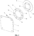
- pairs of magnets 9 in base plate 1 are positioned such that there is one magnet 9 on each side of each dowel pin pair.
- the magnets 9 are oriented such that their magnetic poles are aligned in the same direction and attract oppositely-disposed magnets 10 ( Figures 2 , 4 ) on intermediate plate 2.
- An alignment pin 11 extends outwardly from base plate 1 to mate with an alignment hole 12 in intermediate plate 2 to assure the rotational alignment during the engagement of base plate 1 with intermediate plate 2, while the interaction of the magnets 9, 10 draws the plates 1, 2 together as will be described below.
- rotational alignment of base plate 1 with intermediate plate 2 can occur by manipulating the polarity of the magnet pairs 9, 10 such that the polarity of the magnets differs along the base plate 1 for example, such that the plates 1, 2 would only coaxially and rotationally engage upon a certain angular orientation of the plates 1, 2, otherwise the plates would not engage and/or repel each other.
- Figure 2 is a rear isometric view of the mount of Figure 1 .
- Three hardened balls 13 disposed within pockets 14 are situated on a mating surface 15 of intermediate plate 2, such that the location of the balls 13 correspond with the reference alignment regions 5 on base plate 1.
- the balls 13 are preferably pressed into precisely positioned mounting holes or pockets 14 in plate 2 using manufacturing fixtures, such that they extend outwardly at precise distances from mating surface 15.
- An alternate embodiment would allow for individual adjustability of each ball position, such as through the use of integrated adjustment screws, prior to being affixed in position.
- mating balls 13 and dowel pin pairs 6 form a kinematic mounting seat that enable base plate 1 and intermediate plate 2 to repeatedly be engaged and disengaged, such that each time the plates are engaged the change in position of one plate with respect to the other is negligible from one engagement to the next.
- the embodiment of the present arrangement allows a user to vary, change and interchange dissector plates relative to the sensor in the event it is desired to, for example, change the distance between the dissector plate and the sensor depending on the specific environment or operating conditions.
- a user can be provided with a system, for example, comprising a single sensor mounted to a base plate and a plurality of interchangeable dissector mounts each mounted to intermediate plates (as shown, for example, in Figures 3 and 4 ) that are designed to mate with the base plate as described herein. It is preferred, in such an example, that each interchangeable dissector mount is calibrated with the base plate, where such calibration could occur at the manufacturer's location. During this calibration various optical parameters of the dissector, such as, but not limited to, focal distance and inter-lens distances, relative to the sensor are measured and saved so that these parameters can be used by a software application that uses the sensor data to calculate the wave front incident on the dissector.
- the three paired pressed dowel pin pairs 6 and three hardened balls 13 are one embodiment of a kinematic seat, in which each ball makes two points of contact with each dowel pin pair 6 for a total of six constraining points, one per degree of freedom.
- the illustrated embodiments show the dowel pin pairs 6 on the base plate 1, and the hardened balls 13 on the intermediate plate 2, it will be appreciated that the dowel pin pairs 6 could be on the intermediate plate 2, and the hardened balls 13 could be on the base plate 1, as the case may be.
- the base plate 1 could have a mix of dowel pin pairs and balls that cooperatively mate with a similar mix on the intermediate plate, as long as the kinematic mounting relationship between the two plates is maintained.
- various kinematic arrangements other than that shown in the present embodiments are contemplated, such as a standard kinematic mount where one ball contacts a conical or pyramid-shaped hole, another ball contacts a v-groove and the third ball rests on a flat surface.
- magnets 9, 10 are strategically mounted in the plates as initially discussed above.
- the size and strength of the magnets are selected to assure the engaged plates do not move with respect to each other during normal handling and use.
- the combined forces between the opposing magnets are preferably strong enough such that it would not be difficult to remove the base plate 1 from intermediate plate 2 using solely finger strength.
- a threaded hole 16 in intermediate plate 2 allows one to use a tool (not shown), such as a screw for example, to assist with the disengagement of the joined plates 3 and 2 with base plate 1 to the extent that it is difficult to obtain a finger purchase on the plates 2, 3.
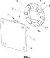
- a through-hole 17 is strategically located in the wave front dissector plate 3 that provides access through the plate 3 to the threaded hole 16 or the like in intermediate plate 2.
- a tool such as a screw (not shown) is inserted through the through-hole 17 and into the threaded hole 16 and thereafter functions as a handle for gripping the plates 2 and 3 through the engagement of the tool with the threaded hole 16 and further functions as a lever for assisting with the separation of the base plate from the intermediate plate 2.
- the tool may be removed after disengagement of the plates 1, 2, or the tool may reside in the threaded hole 16 in preparation for re-engagement of the plates 2, 3 with the base plate 1 or a different base plate (not shown) in another system (not shown).
- two or more holes could be positioned on the plates 2, 3 to assist in the disengagement of the plates 1, 2.
- Intermediate plate 2 and wave front dissector plate 3 are aligned separately from base plate 1.
- a precision manufacturing fixture is used to permanently affix plates 2 and 3 together as shown in Figures 3 and 4 .
- a wave front dissector 18 is preferably permanently mounted in plate 3 using adhesive or other means known in the art to assure the proper alignment of the dissector 18 with respect to the dissector mount.
- Plate 3 is designed such that the wave front dissector 18, specified to be square for this embodiment, sits in a square well 19.
- Intermediate plate 2 and dissector plate 3 are aligned separately from base plate 1. More specifically, a precision manufacturing fixture is used to permanently affix plates 2 and 3 together.
- the design and assembly of manufacturing fixtures significantly contribute to enable the assembly of the removable subassemblies (elements 2, 10, 13, 3, 18) to properly mate with base plate subassemblies (elements 1, 6, 9, 11).
- One manufacturing fixture is used to precisely align the six degrees of freedom of the base plate subassembly's reference plane, defined as the plane that includes the mechanical axes of the dowel pins 6, with respect to the sensor 4, and maintain the alignment while the sensor and the base plate subassembly are permanently affixed.
- a separate manufacturing fixture is used to align and set the removable subassemblies' reference plane, defined as the plane created by the centers of balls 13, relative to a surface of the wave front dissector 18, as well as the angular alignment of the wave front dissector 18 relative to the orientation of the balls 13.
- the precision six-axis alignment of base plate 1 to the sensor 4, such as a CCD array can be simplified to a single rotational adjustment and dissector plate 3 is aligned when intermediate plate 2 is already mated with base plate 1 using manufacturing fixtures.
- base plate 1 is preferably permanently affixed to a sensor 4, such as a CCD array. This can be done using an adhesive or other means known in the art.
- Figure 5 illustrates one embodiment of the assembly of Figure 1 with the sensor not shown attached to the base plate 1.
- a groove 20, shown in the embodiment of Figure 5 just below the alignment pin 11, although this location is not critical, is used to align base plate 1 with respect to the sensor 4 (not shown in Figure 5 ) prior to it being affixed to the base plate 1.
- a rod (not shown), or other such straight element, for example, can be set in the groove 20 to cast a shadow on the sensor 4, which can be actively sensed with the sensor 4.
- the groove 20 would be designed into base plate 1 such that the shadow of the rod, or other straight element, is aligned with a row, or column, of the sensor 4, allowing fine rotational alignment of the base plate 1 relative to the sensor 4.
- the groove 20 is also preferably positioned on the base plate 1 such that the utilized straight element would not interfere with the alignment regions 5.
- a means for precisely positioning a wave front dissector such as a lenslet array 18, in front of a sensor 4, such as a CCD sensor.
- This means for positioning addresses six degrees of alignment adjustment: two transverse alignments (in the plane of the sensor) through the use of the balls 13, longitudinal alignment (orthogonal to the sensor) through the use of the ball geometry and the relative orientation of the dowel pins within the pin pairs, rotational alignment about an axis orthogonal to the sensor through the interaction of the balls and the dowel pin pairs, and rotational alignments about two orthogonal axes that are each orthogonal to the prior rotational axis again through the interaction of the balls and the dowel pin pairs.
- the positioning means does not permanently mount the dissector relative to the sensor, but instead allows for the dissectors to be replaced or interchanged with another dissector by the user, while precisely holding the position of the integrated dissector relative to the sensor such that the accuracy and precision of the wave front measurements is not degraded in comparison to measurements made with wave front sensors that permanently mount the dissector relative to the sensor.
- Figure 6 illustrates one embodiment of a kit 30 including a SH sensor system 32 defined by a base plate 34 associated with a sensor 36 (such as a CCD camera, for example), an intermediate plate 44, and a wavefront dissector 40 such as a microlens array housed in a wavefront dissector plate 42, for example.
- Additional wavefront dissectors 50 and 60 can be provided in the kit 30 and/or vended separately for use with the SH sensor system 32, wherein each wavefront dissector, when associated with the SH sensor system 32, may exhibit a different optical characteristic relative to the sensor 36 including, but not limited to, focal length or lens pitch.
- wavefront dissector 50 is positioned further away from the intermediate plate 54 that engages with the base plate 34 as compared with the position of the wavefront dissector 40 relative to its intermediate plate 44, and therefore the wavefront dissector 50 exhibits a greater focal length as compared with the focal length of wavefront dissector 40 or wavefront dissector 60.
- wavefront dissectors 40 and 60 may have the same focal length, one wavefront dissector may have a different lens pitch. Accordingly, various wavefront dissectors may be provided that exhibit differing optical characteristics or features that would be beneficial in a given environment or application.
- a tool 70 having an engagement end 72 for assisting with the engagement and disengagement of the various microlens arrays 40, 50, and 60 with the base plate 34.
- the engagement end 72 of the tool 70 is securely engageable with the openings 46, 56, and 66 provided in the intermediate plates 44, 54, and 64 associated with the wavefront dissectors 40, 50 and 60 respectively to maneuver such wavefront dissectors with intermediate plates through the mount 38 provided on the face of the system 32 (see also the above discussion of the engagement of a tool with through holes 16 and 17 shown, for example, in Figures 1 and 3 ).
- Figure 7 illustrates the SH sensor system 32 with wavefront dissector 40 and dissector plate 42 mounted to the base plate 34.
- the mount 38 is preferably threaded to accommodate filters (not shown) to help prevent the saturation of the sensor pixel provided in the sensor 36 and lens tubes to reduce scattered light and to allow for the mounting of additional optical components (not shown).
- the exchange of wavefront dissectors such as microlens arrays allows for economic switching to different applications requiring different wavefront sensor specifications in terms of spatial resolution (lenslet pitch), focal length, wavefront sensitivity and dynamic range.
- Each microlens array mounted in a wavefront dissector plate can be interfaced with the same base plate 34 and sensor 36.
- one microlens array might comprise a chrome mask microlens array, which prevents light from passing between the microlenses.
- microlens array considerably increases the intensity of the back reflection from the surface of the microlens array however, it can be used over a broad operating wavelength range (300 - 1100 nm).
- Other microlens arrays could be AR-coated (400 - 900 nm) and are suitable for applications that are sensitive to back reflections.
- Other microlens arrays are possible.
- Each microlens array may be pre-mounted to a dissector plate and calibrated relative to the sensor, or it may be provided un-mounted and require mounting to a dissector plate and calibration relative to a sensor.
- FIGS 8 and 9 illustrates the general functional principle behind a SH sensor, which consists basically of an optical sensor, such as a CCD camera, with a microlens array mounted in a defined distance in front of its sensor chip.
- Each microlens generates a spot onto the sensor whereas the spot centroid position depends on the wavefront gradient in front of the lens area.
- Each microlens of the lenslet array collects the light falling onto its aperture and generates a single spot on the detector plane (CCD camera) that is situated a focal length behind the lenslets.
- the spot positions are straight behind the lenses, on the optical axis or each lens, only in the case that the launched wavefront is planar and parallel to the plane of the lenslets. These are termed Reference Spot Positions or Reference Spotfield.
- the current spot positions will be deviated in X and, or, Y direction, that is, every spot will lie away from the optical axis Z of its associated microlens, separated by an angle ⁇ .
- W(x,y) describes the shape of the wavefront so its partial derivation relative to x and y are determined by the spot shift ⁇ x and ⁇ y, respectively as well as by the distance between microlens end detector which is usually the focal length of the microlens f ML .
- Spot deviations ⁇ x and ⁇ y are determined by calculating the centroid coordinates of all detectable spots and subtracting the corresponding reference coordinates afterwards. These spot deviations are integrated within a 2-dimensional integration process that gives the wavefront W(x,y).
Landscapes
- Physics & Mathematics (AREA)
- Spectroscopy & Molecular Physics (AREA)
- General Physics & Mathematics (AREA)
- Telescopes (AREA)
- Photometry And Measurement Of Optical Pulse Characteristics (AREA)
- Length Measuring Devices By Optical Means (AREA)
- Optical Communication System (AREA)
Applications Claiming Priority (2)
| Application Number | Priority Date | Filing Date | Title |
|---|---|---|---|
| US22682109P | 2009-07-20 | 2009-07-20 | |
| PCT/US2010/042558 WO2011011385A2 (en) | 2009-07-20 | 2010-07-20 | Shack hartman sensor with removable lenslet array |
Publications (2)
| Publication Number | Publication Date |
|---|---|
| EP2457072A2 EP2457072A2 (en) | 2012-05-30 |
| EP2457072B1 true EP2457072B1 (en) | 2019-01-23 |
Family
ID=42732733
Family Applications (1)
| Application Number | Title | Priority Date | Filing Date |
|---|---|---|---|
| EP10739756.4A Active EP2457072B1 (en) | 2009-07-20 | 2010-07-20 | Shack hartman sensor with removable lenslet array |
Country Status (7)
| Country | Link |
|---|---|
| US (1) | US8289504B2 (enExample) |
| EP (1) | EP2457072B1 (enExample) |
| JP (1) | JP5689879B2 (enExample) |
| CN (1) | CN102483358B (enExample) |
| CA (1) | CA2767900C (enExample) |
| ES (1) | ES2720631T3 (enExample) |
| WO (1) | WO2011011385A2 (enExample) |
Families Citing this family (7)
| Publication number | Priority date | Publication date | Assignee | Title |
|---|---|---|---|---|
| CN103512668B (zh) * | 2013-09-13 | 2016-01-13 | 华中科技大学 | 一种红外图像与波前双模一体化成像探测芯片 |
| JP7199835B2 (ja) | 2018-05-25 | 2023-01-06 | キヤノン株式会社 | 波面センサ、波面計測装置、光学素子の製造方法、光学系の製造方法 |
| FR3083800B1 (fr) | 2018-07-13 | 2020-12-25 | Total Marketing Services | Composition refroidissante et ignifugeante pour systeme de propulsion d'un vehicule electrique ou hybride |
| FR3083803B1 (fr) | 2018-07-13 | 2020-07-31 | Total Marketing Services | Composition de refroidissement et ignifugeante pour systeme de propulsion d'un vehicule electrique ou hybride |
| FR3083802B1 (fr) | 2018-07-13 | 2021-02-12 | Total Marketing Services | Composition refroidissante et ignifugeante pour systeme de propulsion d'un vehicule electrique ou hybride |
| FR3083801B1 (fr) | 2018-07-13 | 2021-02-12 | Total Marketing Services | Composition de refroidissement et ignifugeante pour systeme de propulsion d'un vehicule electrique ou hybride |
| WO2026041484A1 (de) * | 2024-08-22 | 2026-02-26 | Aumovio Germany Gmbh | Projektionsgerät |
Family Cites Families (13)
| Publication number | Priority date | Publication date | Assignee | Title |
|---|---|---|---|---|
| US5406412A (en) * | 1993-06-17 | 1995-04-11 | Visidyne, Inc. | High-resolution synthetic aperture adaptive optics system |
| US5493391A (en) * | 1994-07-11 | 1996-02-20 | Sandia Corporation | One dimensional wavefront distortion sensor comprising a lens array system |
| US5629765A (en) * | 1995-12-15 | 1997-05-13 | Adaptive Optics Associates, Inc. | Wavefront measuring system with integral geometric reference (IGR) |
| US5936720A (en) * | 1996-07-10 | 1999-08-10 | Neal; Daniel R. | Beam characterization by wavefront sensor |
| US5748827A (en) | 1996-10-23 | 1998-05-05 | University Of Washington | Two-stage kinematic mount |
| US6565209B2 (en) * | 2000-04-25 | 2003-05-20 | Alcon Universal Ltd. | Range-extending system and spatial filter for enhancing Hartmann-Shack images and associated methods |
| US7646544B2 (en) * | 2005-05-14 | 2010-01-12 | Batchko Robert G | Fluidic optical devices |
| GB0026407D0 (en) * | 2000-10-28 | 2000-12-13 | Renishaw Plc | Mounting module for an optical element |
| US6582079B2 (en) * | 2001-06-05 | 2003-06-24 | Metrologic Instruments, Inc. | Modular adaptive optical subsystem for integration with a fundus camera body and CCD camera unit and improved fundus camera employing same |
| US7078665B2 (en) * | 2002-07-09 | 2006-07-18 | Wavefront Sciences, Inc. | System and method of wavefront sensing for determining a location of focal spot |
| US20060186312A1 (en) * | 2005-02-23 | 2006-08-24 | Zino Altman | Apparatus and method for optical wavefront analysis using active light modulation |
| WO2007070006A1 (en) * | 2005-12-13 | 2007-06-21 | Agency For Science, Technology And Research | Optical wavefront sensor |
| JP2007279396A (ja) * | 2006-04-06 | 2007-10-25 | Fujifilm Corp | カメラシステム |
-
2010
- 2010-07-20 WO PCT/US2010/042558 patent/WO2011011385A2/en not_active Ceased
- 2010-07-20 JP JP2012521724A patent/JP5689879B2/ja not_active Expired - Fee Related
- 2010-07-20 US US12/839,719 patent/US8289504B2/en active Active
- 2010-07-20 CN CN201080032698.5A patent/CN102483358B/zh not_active Expired - Fee Related
- 2010-07-20 ES ES10739756T patent/ES2720631T3/es active Active
- 2010-07-20 CA CA2767900A patent/CA2767900C/en active Active
- 2010-07-20 EP EP10739756.4A patent/EP2457072B1/en active Active
Non-Patent Citations (1)
| Title |
|---|
| None * |
Also Published As
| Publication number | Publication date |
|---|---|
| US8289504B2 (en) | 2012-10-16 |
| CA2767900C (en) | 2017-08-15 |
| EP2457072A2 (en) | 2012-05-30 |
| JP2012533758A (ja) | 2012-12-27 |
| WO2011011385A2 (en) | 2011-01-27 |
| CN102483358B (zh) | 2014-03-05 |
| ES2720631T3 (es) | 2019-07-23 |
| US20110013178A1 (en) | 2011-01-20 |
| WO2011011385A3 (en) | 2011-04-28 |
| JP5689879B2 (ja) | 2015-03-25 |
| CA2767900A1 (en) | 2011-01-27 |
| CN102483358A (zh) | 2012-05-30 |
Similar Documents
| Publication | Publication Date | Title |
|---|---|---|
| EP2457072B1 (en) | Shack hartman sensor with removable lenslet array | |
| JP5909365B2 (ja) | 接触プローブ | |
| JP7254858B2 (ja) | 可動レーザビームを備えたモジュール式対物アセンブリ | |
| US20110154645A1 (en) | Apparatus for forming a kinematic coupling and related methods | |
| US7312859B2 (en) | Optical fiber inspection device | |
| JP4633484B2 (ja) | 光学素子の支持機構 | |
| US20120092655A1 (en) | Inspection system utilizing solid immersion lenses | |
| TW201523058A (zh) | 攝影模組的製造方法以及攝影模組的製造裝置 | |
| JP6051361B2 (ja) | 形状可変x線ミラーシステム | |
| US9645345B2 (en) | Optical element alignment and retention for optical instruments | |
| JP2002244018A (ja) | ミラーの距離、角度調整機構 | |
| EP3899418A1 (en) | Precision coupling | |
| CN213714691U (zh) | 镜头透光率检测设备 | |
| CN118140115A (zh) | 用于材料去除差分计量的偏转测量装置 | |
| TW202108977A (zh) | 保持具及測量用治具 | |
| EP1526396A1 (en) | Polarization conditioner packaging and collimator alignment mechanism | |
| JP2001281514A (ja) | 光学要素保持機構および該光学要素保持機構を含む光学機器 | |
| US7689091B1 (en) | Unitary fiber clamp with flexible members and a member mover | |
| CN214375602U (zh) | 用于对准光轴的框架部件以及激光聚焦仪器 | |
| JP2003247909A (ja) | 光通信用の多芯コネクタ或いは多芯ファイバアレーのフェルール偏心量測定装置における入射光照明装置および光ファイバ位置測定装置 | |
| JP2007127445A (ja) | エタロン装置及びその製造方法 | |
| GB2573087A (en) | Improvements in or relating to optical components | |
| PL223500B1 (pl) | Sposób pomiaru położenia i współosiowości otworów | |
| CN121028320A (zh) | 光学装置及其装配方法 | |
| JPH026918A (ja) | 走査光学装置のレンズ保持構造 |
Legal Events
| Date | Code | Title | Description |
|---|---|---|---|
| PUAI | Public reference made under article 153(3) epc to a published international application that has entered the european phase |
Free format text: ORIGINAL CODE: 0009012 |
|
| 17P | Request for examination filed |
Effective date: 20120217 |
|
| AK | Designated contracting states |
Kind code of ref document: A2 Designated state(s): AL AT BE BG CH CY CZ DE DK EE ES FI FR GB GR HR HU IE IS IT LI LT LU LV MC MK MT NL NO PL PT RO SE SI SK SM TR |
|
| DAX | Request for extension of the european patent (deleted) | ||
| STAA | Information on the status of an ep patent application or granted ep patent |
Free format text: STATUS: EXAMINATION IS IN PROGRESS |
|
| 17Q | First examination report despatched |
Effective date: 20161222 |
|
| GRAP | Despatch of communication of intention to grant a patent |
Free format text: ORIGINAL CODE: EPIDOSNIGR1 |
|
| STAA | Information on the status of an ep patent application or granted ep patent |
Free format text: STATUS: GRANT OF PATENT IS INTENDED |
|
| INTG | Intention to grant announced |
Effective date: 20181005 |
|
| RAP1 | Party data changed (applicant data changed or rights of an application transferred) |
Owner name: THORLABS, INC. |
|
| GRAS | Grant fee paid |
Free format text: ORIGINAL CODE: EPIDOSNIGR3 |
|
| GRAA | (expected) grant |
Free format text: ORIGINAL CODE: 0009210 |
|
| STAA | Information on the status of an ep patent application or granted ep patent |
Free format text: STATUS: THE PATENT HAS BEEN GRANTED |
|
| AK | Designated contracting states |
Kind code of ref document: B1 Designated state(s): AL AT BE BG CH CY CZ DE DK EE ES FI FR GB GR HR HU IE IS IT LI LT LU LV MC MK MT NL NO PL PT RO SE SI SK SM TR |
|
| REG | Reference to a national code |
Ref country code: GB Ref legal event code: FG4D |
|
| REG | Reference to a national code |
Ref country code: CH Ref legal event code: EP |
|
| REG | Reference to a national code |
Ref country code: AT Ref legal event code: REF Ref document number: 1091811 Country of ref document: AT Kind code of ref document: T Effective date: 20190215 |
|
| REG | Reference to a national code |
Ref country code: IE Ref legal event code: FG4D |
|
| REG | Reference to a national code |
Ref country code: DE Ref legal event code: R096 Ref document number: 602010056721 Country of ref document: DE |
|
| REG | Reference to a national code |
Ref country code: SE Ref legal event code: TRGR |
|
| REG | Reference to a national code |
Ref country code: NL Ref legal event code: MP Effective date: 20190123 |
|
| PG25 | Lapsed in a contracting state [announced via postgrant information from national office to epo] |
Ref country code: NL Free format text: LAPSE BECAUSE OF FAILURE TO SUBMIT A TRANSLATION OF THE DESCRIPTION OR TO PAY THE FEE WITHIN THE PRESCRIBED TIME-LIMIT Effective date: 20190123 |
|
| REG | Reference to a national code |
Ref country code: ES Ref legal event code: FG2A Ref document number: 2720631 Country of ref document: ES Kind code of ref document: T3 Effective date: 20190723 |
|
| PG25 | Lapsed in a contracting state [announced via postgrant information from national office to epo] |
Ref country code: FI Free format text: LAPSE BECAUSE OF FAILURE TO SUBMIT A TRANSLATION OF THE DESCRIPTION OR TO PAY THE FEE WITHIN THE PRESCRIBED TIME-LIMIT Effective date: 20190123 Ref country code: NO Free format text: LAPSE BECAUSE OF FAILURE TO SUBMIT A TRANSLATION OF THE DESCRIPTION OR TO PAY THE FEE WITHIN THE PRESCRIBED TIME-LIMIT Effective date: 20190423 Ref country code: PL Free format text: LAPSE BECAUSE OF FAILURE TO SUBMIT A TRANSLATION OF THE DESCRIPTION OR TO PAY THE FEE WITHIN THE PRESCRIBED TIME-LIMIT Effective date: 20190123 Ref country code: LT Free format text: LAPSE BECAUSE OF FAILURE TO SUBMIT A TRANSLATION OF THE DESCRIPTION OR TO PAY THE FEE WITHIN THE PRESCRIBED TIME-LIMIT Effective date: 20190123 Ref country code: PT Free format text: LAPSE BECAUSE OF FAILURE TO SUBMIT A TRANSLATION OF THE DESCRIPTION OR TO PAY THE FEE WITHIN THE PRESCRIBED TIME-LIMIT Effective date: 20190523 |
|
| REG | Reference to a national code |
Ref country code: AT Ref legal event code: MK05 Ref document number: 1091811 Country of ref document: AT Kind code of ref document: T Effective date: 20190123 |
|
| PG25 | Lapsed in a contracting state [announced via postgrant information from national office to epo] |
Ref country code: LV Free format text: LAPSE BECAUSE OF FAILURE TO SUBMIT A TRANSLATION OF THE DESCRIPTION OR TO PAY THE FEE WITHIN THE PRESCRIBED TIME-LIMIT Effective date: 20190123 Ref country code: BG Free format text: LAPSE BECAUSE OF FAILURE TO SUBMIT A TRANSLATION OF THE DESCRIPTION OR TO PAY THE FEE WITHIN THE PRESCRIBED TIME-LIMIT Effective date: 20190423 Ref country code: IS Free format text: LAPSE BECAUSE OF FAILURE TO SUBMIT A TRANSLATION OF THE DESCRIPTION OR TO PAY THE FEE WITHIN THE PRESCRIBED TIME-LIMIT Effective date: 20190523 Ref country code: GR Free format text: LAPSE BECAUSE OF FAILURE TO SUBMIT A TRANSLATION OF THE DESCRIPTION OR TO PAY THE FEE WITHIN THE PRESCRIBED TIME-LIMIT Effective date: 20190424 Ref country code: HR Free format text: LAPSE BECAUSE OF FAILURE TO SUBMIT A TRANSLATION OF THE DESCRIPTION OR TO PAY THE FEE WITHIN THE PRESCRIBED TIME-LIMIT Effective date: 20190123 |
|
| REG | Reference to a national code |
Ref country code: DE Ref legal event code: R097 Ref document number: 602010056721 Country of ref document: DE |
|
| PG25 | Lapsed in a contracting state [announced via postgrant information from national office to epo] |
Ref country code: DK Free format text: LAPSE BECAUSE OF FAILURE TO SUBMIT A TRANSLATION OF THE DESCRIPTION OR TO PAY THE FEE WITHIN THE PRESCRIBED TIME-LIMIT Effective date: 20190123 Ref country code: EE Free format text: LAPSE BECAUSE OF FAILURE TO SUBMIT A TRANSLATION OF THE DESCRIPTION OR TO PAY THE FEE WITHIN THE PRESCRIBED TIME-LIMIT Effective date: 20190123 Ref country code: SK Free format text: LAPSE BECAUSE OF FAILURE TO SUBMIT A TRANSLATION OF THE DESCRIPTION OR TO PAY THE FEE WITHIN THE PRESCRIBED TIME-LIMIT Effective date: 20190123 Ref country code: AL Free format text: LAPSE BECAUSE OF FAILURE TO SUBMIT A TRANSLATION OF THE DESCRIPTION OR TO PAY THE FEE WITHIN THE PRESCRIBED TIME-LIMIT Effective date: 20190123 Ref country code: CZ Free format text: LAPSE BECAUSE OF FAILURE TO SUBMIT A TRANSLATION OF THE DESCRIPTION OR TO PAY THE FEE WITHIN THE PRESCRIBED TIME-LIMIT Effective date: 20190123 Ref country code: RO Free format text: LAPSE BECAUSE OF FAILURE TO SUBMIT A TRANSLATION OF THE DESCRIPTION OR TO PAY THE FEE WITHIN THE PRESCRIBED TIME-LIMIT Effective date: 20190123 |
|
| PG25 | Lapsed in a contracting state [announced via postgrant information from national office to epo] |
Ref country code: SM Free format text: LAPSE BECAUSE OF FAILURE TO SUBMIT A TRANSLATION OF THE DESCRIPTION OR TO PAY THE FEE WITHIN THE PRESCRIBED TIME-LIMIT Effective date: 20190123 |
|
| PLBE | No opposition filed within time limit |
Free format text: ORIGINAL CODE: 0009261 |
|
| STAA | Information on the status of an ep patent application or granted ep patent |
Free format text: STATUS: NO OPPOSITION FILED WITHIN TIME LIMIT |
|
| PG25 | Lapsed in a contracting state [announced via postgrant information from national office to epo] |
Ref country code: AT Free format text: LAPSE BECAUSE OF FAILURE TO SUBMIT A TRANSLATION OF THE DESCRIPTION OR TO PAY THE FEE WITHIN THE PRESCRIBED TIME-LIMIT Effective date: 20190123 |
|
| 26N | No opposition filed |
Effective date: 20191024 |
|
| PG25 | Lapsed in a contracting state [announced via postgrant information from national office to epo] |
Ref country code: MC Free format text: LAPSE BECAUSE OF FAILURE TO SUBMIT A TRANSLATION OF THE DESCRIPTION OR TO PAY THE FEE WITHIN THE PRESCRIBED TIME-LIMIT Effective date: 20190123 Ref country code: SI Free format text: LAPSE BECAUSE OF FAILURE TO SUBMIT A TRANSLATION OF THE DESCRIPTION OR TO PAY THE FEE WITHIN THE PRESCRIBED TIME-LIMIT Effective date: 20190123 |
|
| PG25 | Lapsed in a contracting state [announced via postgrant information from national office to epo] |
Ref country code: TR Free format text: LAPSE BECAUSE OF FAILURE TO SUBMIT A TRANSLATION OF THE DESCRIPTION OR TO PAY THE FEE WITHIN THE PRESCRIBED TIME-LIMIT Effective date: 20190123 |
|
| REG | Reference to a national code |
Ref country code: BE Ref legal event code: MM Effective date: 20190731 |
|
| PG25 | Lapsed in a contracting state [announced via postgrant information from national office to epo] |
Ref country code: LU Free format text: LAPSE BECAUSE OF NON-PAYMENT OF DUE FEES Effective date: 20190720 Ref country code: BE Free format text: LAPSE BECAUSE OF NON-PAYMENT OF DUE FEES Effective date: 20190731 |
|
| PG25 | Lapsed in a contracting state [announced via postgrant information from national office to epo] |
Ref country code: IE Free format text: LAPSE BECAUSE OF NON-PAYMENT OF DUE FEES Effective date: 20190720 |
|
| PG25 | Lapsed in a contracting state [announced via postgrant information from national office to epo] |
Ref country code: CY Free format text: LAPSE BECAUSE OF FAILURE TO SUBMIT A TRANSLATION OF THE DESCRIPTION OR TO PAY THE FEE WITHIN THE PRESCRIBED TIME-LIMIT Effective date: 20190123 |
|
| PG25 | Lapsed in a contracting state [announced via postgrant information from national office to epo] |
Ref country code: HU Free format text: LAPSE BECAUSE OF FAILURE TO SUBMIT A TRANSLATION OF THE DESCRIPTION OR TO PAY THE FEE WITHIN THE PRESCRIBED TIME-LIMIT; INVALID AB INITIO Effective date: 20100720 Ref country code: MT Free format text: LAPSE BECAUSE OF FAILURE TO SUBMIT A TRANSLATION OF THE DESCRIPTION OR TO PAY THE FEE WITHIN THE PRESCRIBED TIME-LIMIT Effective date: 20190123 |
|
| PG25 | Lapsed in a contracting state [announced via postgrant information from national office to epo] |
Ref country code: MK Free format text: LAPSE BECAUSE OF FAILURE TO SUBMIT A TRANSLATION OF THE DESCRIPTION OR TO PAY THE FEE WITHIN THE PRESCRIBED TIME-LIMIT Effective date: 20190123 |
|
| PGFP | Annual fee paid to national office [announced via postgrant information from national office to epo] |
Ref country code: SE Payment date: 20220727 Year of fee payment: 13 Ref country code: IT Payment date: 20220721 Year of fee payment: 13 Ref country code: ES Payment date: 20220801 Year of fee payment: 13 |
|
| PGFP | Annual fee paid to national office [announced via postgrant information from national office to epo] |
Ref country code: FR Payment date: 20220725 Year of fee payment: 13 |
|
| PGFP | Annual fee paid to national office [announced via postgrant information from national office to epo] |
Ref country code: CH Payment date: 20220808 Year of fee payment: 13 |
|
| PGFP | Annual fee paid to national office [announced via postgrant information from national office to epo] |
Ref country code: GB Payment date: 20230727 Year of fee payment: 14 |
|
| PGFP | Annual fee paid to national office [announced via postgrant information from national office to epo] |
Ref country code: DE Payment date: 20230727 Year of fee payment: 14 |
|
| REG | Reference to a national code |
Ref country code: CH Ref legal event code: PL |
|
| REG | Reference to a national code |
Ref country code: SE Ref legal event code: EUG |
|
| PG25 | Lapsed in a contracting state [announced via postgrant information from national office to epo] |
Ref country code: CH Free format text: LAPSE BECAUSE OF NON-PAYMENT OF DUE FEES Effective date: 20230731 |
|
| PG25 | Lapsed in a contracting state [announced via postgrant information from national office to epo] |
Ref country code: SE Free format text: LAPSE BECAUSE OF NON-PAYMENT OF DUE FEES Effective date: 20230721 Ref country code: FR Free format text: LAPSE BECAUSE OF NON-PAYMENT OF DUE FEES Effective date: 20230731 |
|
| PG25 | Lapsed in a contracting state [announced via postgrant information from national office to epo] |
Ref country code: IT Free format text: LAPSE BECAUSE OF NON-PAYMENT OF DUE FEES Effective date: 20230720 |
|
| REG | Reference to a national code |
Ref country code: ES Ref legal event code: FD2A Effective date: 20240830 |
|
| PG25 | Lapsed in a contracting state [announced via postgrant information from national office to epo] |
Ref country code: ES Free format text: LAPSE BECAUSE OF NON-PAYMENT OF DUE FEES Effective date: 20230721 |
|
| PG25 | Lapsed in a contracting state [announced via postgrant information from national office to epo] |
Ref country code: ES Free format text: LAPSE BECAUSE OF NON-PAYMENT OF DUE FEES Effective date: 20230721 |
|
| REG | Reference to a national code |
Ref country code: DE Ref legal event code: R119 Ref document number: 602010056721 Country of ref document: DE |
|
| GBPC | Gb: european patent ceased through non-payment of renewal fee |
Effective date: 20240720 |
|
| PG25 | Lapsed in a contracting state [announced via postgrant information from national office to epo] |
Ref country code: DE Free format text: LAPSE BECAUSE OF NON-PAYMENT OF DUE FEES Effective date: 20250201 |
|
| PG25 | Lapsed in a contracting state [announced via postgrant information from national office to epo] |
Ref country code: GB Free format text: LAPSE BECAUSE OF NON-PAYMENT OF DUE FEES Effective date: 20240720 |