EP2457032B1 - Solar concentrator with improved manufacturabillty and efficiency - Google Patents
Solar concentrator with improved manufacturabillty and efficiency Download PDFInfo
- Publication number
- EP2457032B1 EP2457032B1 EP10802930.7A EP10802930A EP2457032B1 EP 2457032 B1 EP2457032 B1 EP 2457032B1 EP 10802930 A EP10802930 A EP 10802930A EP 2457032 B1 EP2457032 B1 EP 2457032B1
- Authority
- EP
- European Patent Office
- Prior art keywords
- solar
- reflector
- concentrator
- solar radiation
- petals
- Prior art date
- Legal status (The legal status is an assumption and is not a legal conclusion. Google has not performed a legal analysis and makes no representation as to the accuracy of the status listed.)
- Not-in-force
Links
Images


Classifications
-
- F—MECHANICAL ENGINEERING; LIGHTING; HEATING; WEAPONS; BLASTING
- F24—HEATING; RANGES; VENTILATING
- F24S—SOLAR HEAT COLLECTORS; SOLAR HEAT SYSTEMS
- F24S23/00—Arrangements for concentrating solar-rays for solar heat collectors
- F24S23/70—Arrangements for concentrating solar-rays for solar heat collectors with reflectors
- F24S23/71—Arrangements for concentrating solar-rays for solar heat collectors with reflectors with parabolic reflective surfaces
-
- F—MECHANICAL ENGINEERING; LIGHTING; HEATING; WEAPONS; BLASTING
- F24—HEATING; RANGES; VENTILATING
- F24S—SOLAR HEAT COLLECTORS; SOLAR HEAT SYSTEMS
- F24S23/00—Arrangements for concentrating solar-rays for solar heat collectors
- F24S23/70—Arrangements for concentrating solar-rays for solar heat collectors with reflectors
- F24S23/79—Arrangements for concentrating solar-rays for solar heat collectors with reflectors with spaced and opposed interacting reflective surfaces
-
- F—MECHANICAL ENGINEERING; LIGHTING; HEATING; WEAPONS; BLASTING
- F24—HEATING; RANGES; VENTILATING
- F24S—SOLAR HEAT COLLECTORS; SOLAR HEAT SYSTEMS
- F24S23/00—Arrangements for concentrating solar-rays for solar heat collectors
- F24S23/70—Arrangements for concentrating solar-rays for solar heat collectors with reflectors
- F24S23/80—Arrangements for concentrating solar-rays for solar heat collectors with reflectors having discontinuous faces
-
- F—MECHANICAL ENGINEERING; LIGHTING; HEATING; WEAPONS; BLASTING
- F24—HEATING; RANGES; VENTILATING
- F24S—SOLAR HEAT COLLECTORS; SOLAR HEAT SYSTEMS
- F24S23/00—Arrangements for concentrating solar-rays for solar heat collectors
- F24S23/70—Arrangements for concentrating solar-rays for solar heat collectors with reflectors
- F24S23/82—Arrangements for concentrating solar-rays for solar heat collectors with reflectors characterised by the material or the construction of the reflector
-
- F—MECHANICAL ENGINEERING; LIGHTING; HEATING; WEAPONS; BLASTING
- F24—HEATING; RANGES; VENTILATING
- F24S—SOLAR HEAT COLLECTORS; SOLAR HEAT SYSTEMS
- F24S50/00—Arrangements for controlling solar heat collectors
- F24S50/20—Arrangements for controlling solar heat collectors for tracking
-
- G—PHYSICS
- G01—MEASURING; TESTING
- G01D—MEASURING NOT SPECIALLY ADAPTED FOR A SPECIFIC VARIABLE; ARRANGEMENTS FOR MEASURING TWO OR MORE VARIABLES NOT COVERED IN A SINGLE OTHER SUBCLASS; TARIFF METERING APPARATUS; MEASURING OR TESTING NOT OTHERWISE PROVIDED FOR
- G01D5/00—Mechanical means for transferring the output of a sensing member; Means for converting the output of a sensing member to another variable where the form or nature of the sensing member does not constrain the means for converting; Transducers not specially adapted for a specific variable
- G01D5/26—Mechanical means for transferring the output of a sensing member; Means for converting the output of a sensing member to another variable where the form or nature of the sensing member does not constrain the means for converting; Transducers not specially adapted for a specific variable characterised by optical transfer means, i.e. using infrared, visible, or ultraviolet light
- G01D5/32—Mechanical means for transferring the output of a sensing member; Means for converting the output of a sensing member to another variable where the form or nature of the sensing member does not constrain the means for converting; Transducers not specially adapted for a specific variable characterised by optical transfer means, i.e. using infrared, visible, or ultraviolet light with attenuation or whole or partial obturation of beams of light
- G01D5/34—Mechanical means for transferring the output of a sensing member; Means for converting the output of a sensing member to another variable where the form or nature of the sensing member does not constrain the means for converting; Transducers not specially adapted for a specific variable characterised by optical transfer means, i.e. using infrared, visible, or ultraviolet light with attenuation or whole or partial obturation of beams of light the beams of light being detected by photocells
- G01D5/347—Mechanical means for transferring the output of a sensing member; Means for converting the output of a sensing member to another variable where the form or nature of the sensing member does not constrain the means for converting; Transducers not specially adapted for a specific variable characterised by optical transfer means, i.e. using infrared, visible, or ultraviolet light with attenuation or whole or partial obturation of beams of light the beams of light being detected by photocells using displacement encoding scales
- G01D5/3473—Circular or rotary encoders
-
- H—ELECTRICITY
- H02—GENERATION; CONVERSION OR DISTRIBUTION OF ELECTRIC POWER
- H02S—GENERATION OF ELECTRIC POWER BY CONVERSION OF INFRARED RADIATION, VISIBLE LIGHT OR ULTRAVIOLET LIGHT, e.g. USING PHOTOVOLTAIC [PV] MODULES
- H02S20/00—Supporting structures for PV modules
- H02S20/30—Supporting structures being movable or adjustable, e.g. for angle adjustment
- H02S20/32—Supporting structures being movable or adjustable, e.g. for angle adjustment specially adapted for solar tracking
-
- H—ELECTRICITY
- H02—GENERATION; CONVERSION OR DISTRIBUTION OF ELECTRIC POWER
- H02S—GENERATION OF ELECTRIC POWER BY CONVERSION OF INFRARED RADIATION, VISIBLE LIGHT OR ULTRAVIOLET LIGHT, e.g. USING PHOTOVOLTAIC [PV] MODULES
- H02S40/00—Components or accessories in combination with PV modules, not provided for in groups H02S10/00 - H02S30/00
-
- H—ELECTRICITY
- H02—GENERATION; CONVERSION OR DISTRIBUTION OF ELECTRIC POWER
- H02S—GENERATION OF ELECTRIC POWER BY CONVERSION OF INFRARED RADIATION, VISIBLE LIGHT OR ULTRAVIOLET LIGHT, e.g. USING PHOTOVOLTAIC [PV] MODULES
- H02S40/00—Components or accessories in combination with PV modules, not provided for in groups H02S10/00 - H02S30/00
- H02S40/40—Thermal components
- H02S40/44—Means to utilise heat energy, e.g. hybrid systems producing warm water and electricity at the same time
-
- H—ELECTRICITY
- H10—SEMICONDUCTOR DEVICES; ELECTRIC SOLID-STATE DEVICES NOT OTHERWISE PROVIDED FOR
- H10F—INORGANIC SEMICONDUCTOR DEVICES SENSITIVE TO INFRARED RADIATION, LIGHT, ELECTROMAGNETIC RADIATION OF SHORTER WAVELENGTH OR CORPUSCULAR RADIATION
- H10F77/00—Constructional details of devices covered by this subclass
- H10F77/40—Optical elements or arrangements
- H10F77/42—Optical elements or arrangements directly associated or integrated with photovoltaic cells, e.g. light-reflecting means or light-concentrating means
- H10F77/48—Back surface reflectors [BSR]
-
- H—ELECTRICITY
- H10—SEMICONDUCTOR DEVICES; ELECTRIC SOLID-STATE DEVICES NOT OTHERWISE PROVIDED FOR
- H10F—INORGANIC SEMICONDUCTOR DEVICES SENSITIVE TO INFRARED RADIATION, LIGHT, ELECTROMAGNETIC RADIATION OF SHORTER WAVELENGTH OR CORPUSCULAR RADIATION
- H10F77/00—Constructional details of devices covered by this subclass
- H10F77/40—Optical elements or arrangements
- H10F77/42—Optical elements or arrangements directly associated or integrated with photovoltaic cells, e.g. light-reflecting means or light-concentrating means
- H10F77/488—Reflecting light-concentrating means, e.g. parabolic mirrors or concentrators using total internal reflection
-
- H—ELECTRICITY
- H10—SEMICONDUCTOR DEVICES; ELECTRIC SOLID-STATE DEVICES NOT OTHERWISE PROVIDED FOR
- H10F—INORGANIC SEMICONDUCTOR DEVICES SENSITIVE TO INFRARED RADIATION, LIGHT, ELECTROMAGNETIC RADIATION OF SHORTER WAVELENGTH OR CORPUSCULAR RADIATION
- H10F77/00—Constructional details of devices covered by this subclass
- H10F77/60—Arrangements for cooling, heating, ventilating or compensating for temperature fluctuations
- H10F77/63—Arrangements for cooling directly associated or integrated with photovoltaic cells, e.g. heat sinks directly associated with the photovoltaic cells or integrated Peltier elements for active cooling
-
- F—MECHANICAL ENGINEERING; LIGHTING; HEATING; WEAPONS; BLASTING
- F24—HEATING; RANGES; VENTILATING
- F24S—SOLAR HEAT COLLECTORS; SOLAR HEAT SYSTEMS
- F24S23/00—Arrangements for concentrating solar-rays for solar heat collectors
- F24S23/70—Arrangements for concentrating solar-rays for solar heat collectors with reflectors
- F24S2023/87—Reflectors layout
- F24S2023/874—Reflectors formed by assemblies of adjacent similar reflective facets
-
- F—MECHANICAL ENGINEERING; LIGHTING; HEATING; WEAPONS; BLASTING
- F24—HEATING; RANGES; VENTILATING
- F24S—SOLAR HEAT COLLECTORS; SOLAR HEAT SYSTEMS
- F24S50/00—Arrangements for controlling solar heat collectors
- F24S50/20—Arrangements for controlling solar heat collectors for tracking
- F24S2050/25—Calibration means; Methods for initial positioning of solar concentrators or solar receivers
-
- H—ELECTRICITY
- H10—SEMICONDUCTOR DEVICES; ELECTRIC SOLID-STATE DEVICES NOT OTHERWISE PROVIDED FOR
- H10F—INORGANIC SEMICONDUCTOR DEVICES SENSITIVE TO INFRARED RADIATION, LIGHT, ELECTROMAGNETIC RADIATION OF SHORTER WAVELENGTH OR CORPUSCULAR RADIATION
- H10F77/00—Constructional details of devices covered by this subclass
- H10F77/95—Circuit arrangements
- H10F77/953—Circuit arrangements for devices having potential barriers
- H10F77/957—Circuit arrangements for devices having potential barriers for position-sensitive photodetectors, e.g. lateral-effect photodiodes or quadrant photodiodes
-
- Y—GENERAL TAGGING OF NEW TECHNOLOGICAL DEVELOPMENTS; GENERAL TAGGING OF CROSS-SECTIONAL TECHNOLOGIES SPANNING OVER SEVERAL SECTIONS OF THE IPC; TECHNICAL SUBJECTS COVERED BY FORMER USPC CROSS-REFERENCE ART COLLECTIONS [XRACs] AND DIGESTS
- Y02—TECHNOLOGIES OR APPLICATIONS FOR MITIGATION OR ADAPTATION AGAINST CLIMATE CHANGE
- Y02B—CLIMATE CHANGE MITIGATION TECHNOLOGIES RELATED TO BUILDINGS, e.g. HOUSING, HOUSE APPLIANCES OR RELATED END-USER APPLICATIONS
- Y02B10/00—Integration of renewable energy sources in buildings
- Y02B10/20—Solar thermal
-
- Y—GENERAL TAGGING OF NEW TECHNOLOGICAL DEVELOPMENTS; GENERAL TAGGING OF CROSS-SECTIONAL TECHNOLOGIES SPANNING OVER SEVERAL SECTIONS OF THE IPC; TECHNICAL SUBJECTS COVERED BY FORMER USPC CROSS-REFERENCE ART COLLECTIONS [XRACs] AND DIGESTS
- Y02—TECHNOLOGIES OR APPLICATIONS FOR MITIGATION OR ADAPTATION AGAINST CLIMATE CHANGE
- Y02E—REDUCTION OF GREENHOUSE GAS [GHG] EMISSIONS, RELATED TO ENERGY GENERATION, TRANSMISSION OR DISTRIBUTION
- Y02E10/00—Energy generation through renewable energy sources
- Y02E10/40—Solar thermal energy, e.g. solar towers
-
- Y—GENERAL TAGGING OF NEW TECHNOLOGICAL DEVELOPMENTS; GENERAL TAGGING OF CROSS-SECTIONAL TECHNOLOGIES SPANNING OVER SEVERAL SECTIONS OF THE IPC; TECHNICAL SUBJECTS COVERED BY FORMER USPC CROSS-REFERENCE ART COLLECTIONS [XRACs] AND DIGESTS
- Y02—TECHNOLOGIES OR APPLICATIONS FOR MITIGATION OR ADAPTATION AGAINST CLIMATE CHANGE
- Y02E—REDUCTION OF GREENHOUSE GAS [GHG] EMISSIONS, RELATED TO ENERGY GENERATION, TRANSMISSION OR DISTRIBUTION
- Y02E10/00—Energy generation through renewable energy sources
- Y02E10/40—Solar thermal energy, e.g. solar towers
- Y02E10/47—Mountings or tracking
-
- Y—GENERAL TAGGING OF NEW TECHNOLOGICAL DEVELOPMENTS; GENERAL TAGGING OF CROSS-SECTIONAL TECHNOLOGIES SPANNING OVER SEVERAL SECTIONS OF THE IPC; TECHNICAL SUBJECTS COVERED BY FORMER USPC CROSS-REFERENCE ART COLLECTIONS [XRACs] AND DIGESTS
- Y02—TECHNOLOGIES OR APPLICATIONS FOR MITIGATION OR ADAPTATION AGAINST CLIMATE CHANGE
- Y02E—REDUCTION OF GREENHOUSE GAS [GHG] EMISSIONS, RELATED TO ENERGY GENERATION, TRANSMISSION OR DISTRIBUTION
- Y02E10/00—Energy generation through renewable energy sources
- Y02E10/50—Photovoltaic [PV] energy
- Y02E10/52—PV systems with concentrators
-
- Y—GENERAL TAGGING OF NEW TECHNOLOGICAL DEVELOPMENTS; GENERAL TAGGING OF CROSS-SECTIONAL TECHNOLOGIES SPANNING OVER SEVERAL SECTIONS OF THE IPC; TECHNICAL SUBJECTS COVERED BY FORMER USPC CROSS-REFERENCE ART COLLECTIONS [XRACs] AND DIGESTS
- Y02—TECHNOLOGIES OR APPLICATIONS FOR MITIGATION OR ADAPTATION AGAINST CLIMATE CHANGE
- Y02E—REDUCTION OF GREENHOUSE GAS [GHG] EMISSIONS, RELATED TO ENERGY GENERATION, TRANSMISSION OR DISTRIBUTION
- Y02E10/00—Energy generation through renewable energy sources
- Y02E10/60—Thermal-PV hybrids
Definitions
- the present invention relates to a solar concentrator particularly well-suited for low cost applications, with easy assembly and repair and, more particularly, to a solar concentrator comprising a pair of concentric reflectors having a spindle toroid geometry for focusing the collected solar radiation into a ring-shaped focal area, as opposed to the "point" or "line” focus of prior art configurations.
- the incident solar radiation at the surface of the earth has fairly low intensity, somewhat variable depending on the time of the day, season and location of the earth; roughly 800- 1000 watts of thermal energy per square meter of area.
- the key challenges for the solar industry are to harness the solar radiation at high efficiency and significantly low costs, and improve both the ease of global manufacturability of solar technologies and the ease of assembly and implementation by the conventional commercial sector for diverse applications.
- passive solar devices take the form of solar heaters and rooftop solar panels with pipes running underneath that are simply heated from incident solar radiation; the heat transferring to the fluid or air passing through the passive solar devices.
- passive solar radiation intensity is generally too low to be directly useful for most applications that require heat at high temperatures and pressures (such as running HVAC, industrial process heat, turbines, etc.).
- Another category of solar technology takes of the form of flat panels of solar photovoltaic cells that contain semiconductor devices. These devices convert incident solar radiation directly into electricity; the electrical energy output is a direct function of the area of the PV cell array.
- Solar “concentrators” are considered as another category and are designed to reflect the incident solar radiation from a large area onto a smaller focal area in order to concentrate (collect) the solar radiation to generate large amounts of heat that can be transferred to a fluid circulating at the focal area (thus achieving higher temperature and pressure), suitable for various applications where heat of desired quality is needed, such as industrial process heat, HVAC heating and cooling, desalination, dehydration etc., or for steam production to drive turbines in order to generate electricity.
- a hybrid technology has been explored, where solar collectors are used in conjunction with a special type of PV cell; the solar concentration technology directs a high intensity solar radiation beam onto a specialized small number of photovoltaic cells (called concentrator PV cells) at the focal area of the collectors.
- concentrator PV cells photovoltaic cells
- solar concentrator technologies are most widely useful whether the application needs heat or electricity or both. As compared to passive solar technologies or PV cell technologies, solar concentrators provide heat at low-costs and high efficiency.
- a parabolic trough collector One particular type of concentrating collector is known in the art as a parabolic trough collector.
- This type of collector uses an elongated reflective trough having a parabolic cross-section to concentrate the sun's radiation along a focal line extending through the focal points of the parabolic elements forming the trough.
- a conduit is typically positioned along this focal line, with a heat-transferring liquid circulating through the conduit. The liquid will be heated by the sun's energy as it moves through the conduit.
- a solar concentrator may take the form of a parabolic point concentrator, using a plurality of curved mirrors arranged to form a parabolic dish that focuses the incoming solar radiation onto a single point.
- a Stirling engine or cavity receiver is typically placed at the focal point of the dish concentrator to capture the solar energy and convert it into heat (or mechanical) energy.
- Yet another variation of solar concentrator technology is referred to as a "power tower” or “heliostat”, where hundreds of individual parabolic point reflectors are arranged in a solar field and each reflector focuses its beam onto the top of a large central tower where the receiver is housed.
- the advantage of this configuration is that the heat collection from a large collection area of the field is centralized to minimize heat loss and cost of piping.
- the shadowing effects, large land requirements, and other considerations are some of the disadvantages of the power tower types of concentrator technologies.
- CLL Concentrated Linear Fresnel Reflector
- the configurations are usually "application specific" in terms of being designed for the specific geographic conditions of a given site (i.e., a function of the local movements of the sun), or requiring highly planar field for fine mirror alignment, or requiring a large tract of land in a desert, etc.).
- Each implementation also has requirements for specific dimensions (in terms of their surface area, lengths, etc.), offering little flexibility to adapt to application-specific situation.
- the solar collector optics are generally comprised of glass reflectors that must be painstakingly constructed and polished, require costly supporting structures, and thereafter require extensive and tedious installation.
- US 4 919 527 A discloses a solar radiation concentrator having a reflecting surface made of spherical or toroidal facets arranged in a plurality of annular zones.
- the present invention relates to a solar concentrator particularly well-suited for low cost applications, with easy assembly and repair and, more particularly, to a solar concentrator comprising a plurality of concentric reflectors having a spindle toroid geometry for focusing the collected solar radiation into ring-shaped focal areas, as opposed to the "point" or "line” focus of prior art
- This object is met by the solar concentrator of the present invention defined in claim 1. configurations.
- This object is met by the solarconcentrator of the present invention defined in claim 1.
- a pair of reflectors is shown.
- the solar concentrator of the present invention may utilize any number of reflectors having the preferred spindle toroid geometry.
- each reflector is formed to exhibit a spindle toroid geometry and thus focus the incoming solar radiation into a ring-like focal area.
- the spindle toroid reflector creates a ring-like focal area, concentrating a larger amount of the incoming energy into a small region while not requiring the precise alignment between receiver and concentrator associated with the prior art dish ("point") concentrator.
- each reflector is formed of a plurality of curved petals that are disposed in a contiguous, keystone arrangement that requires minimal fixturing (e.g., epoxy) to hold the petals in place.
- fixturing e.g., epoxy
- each petal is of monocoque construction, where the outer "skin" of the petal also functions to provide the necessary rigidity to the petal and carries all of the applied load.
- Each petal may have a reflective outer surface or may be formed itself of a reflective material disposed across its outer surface. Materials such as aluminum or elastically-formed thin glass are suitable for this reflective surface.
- the solar concentrator of the present invention may be configured in conjunction with a Cassegrain-type system, where a secondary reflector disposed along the optical axis redirects the concentrated solar radiation into a receiver positioned at another location.
- a receiver in the form of a concentrated solar thermal (CST) system or concentrated photo-voltaic (CPV) cell may be disposed at the ring-like focal area.
- a dielectric filter may be disposed at the ring-like focal area and used to direct the wavelengths associated with thermal energy production into a thermal-based receiver, while directing the wavelengths associated with electrical energy production into, for example, a PV structure.
- FIG. 1 is an isometric view of an exemplary solar concentrator 10 formed in accordance with the present invention.
- the spindle toroid geometry of the inventive concentrator functions to direct the reflected solar into ring-like regions at the focal area F of concentrator 10.
- the ring-like focal area provides a greater concentration of energy than the "line" focus associated with the prior art trough collectors, without requiring the expensive alignments associated with the prior art "point" focus associated with the prior art dish collectors.
- solar concentrator 10 is shown as comprising a pair of concentric reflectors including an outer reflector 12 and an inner reflector 14, where each reflector is formed of the spindle toroid geometry.
- a pair of reflectors is considered to be exemplary only, any suitable number of reflectors may be utilized to form a particular solar concentrator assembly.
- FIG. 2 is a ray tracing diagram illustrating the concentration of the reflected solar radiation into rings R-12 and R-14, also showing an enlargement of rings R-12 and R-14 for the sake of clarity.
- a spindle torus, as used herein in the formation of reflectors 12 and 14, is created when R ⁇ r, forming a "self-intersecting" surface.
- each of reflector 12 and 14 With this definition of the structure of each of reflector 12 and 14, it can be shown that the focal area of each takes the form of a ring, which allows for a significant concentration of, in this case, solar radiation, into a well-defined, relatively small area for better heat distribution as compared to that prior art collectors with point focus.
- Rings R-12 and R-14 in FIGs. 1 and 2 illustrate this improvement in solar radiation concentration in accordance with the spindle toroid configuration of reflectors 12 and 14.
- the specific geometry of the focal area can be modified to suit different needs; that is, whether solar concentrator 10 is part of a CPV system, HVAC system, industrial heat generation, electricity, or the like.
- the ability to concentrate the solar radiation into such a relatively small area with improved heat distribution by ring focus, and without the need for the expensive, "tight tolerance" optics of prior art solar collectors is considered to be a significant advantage of the arrangement of the present invention.
- each reflector 12, 14 in solar concentrator 10 comprises a plurality of separate reflecting "petals", held in place in a keystone arrangement such that the final reflector structure is self-supporting.
- No additional bracing or support structure is required; this is considered to be a significant advance over prior art concentrator designs that required an extensive support mechanism which added to the weight and cost (as well as construction complexities) of the overall concentrator. Indeed, by eliminating the need for a support structure, the final solar concentrator structure is considerably lighter, easier to assemble on-site, and easier to maneuver than conventional solar collectors.
- FIGs. 4-6 particularly illustrate the keystone construction of solar concentrator 10, where FIG. 4 is an isometric view of outer reflector 12, FIG. 5 is an isometric view of inner reflector 14, and FIG. 6 shows the concentric arrangement of inner reflector 14 disposed to overly outer reflector 12. As noted above, each reflector will separately concentrate the impinging radiation into a ring-like focal area (see FIGs. 1 and 6).
- FIG. 6 in particular illustrates the concentric arrangement of solar concentrator 10, with inner reflector 14 affixed to overly the central area 13 of outer reflector 12 (central area 13 is indicated by the dotted line in FIG. 4 ).
- FIG. 4 clearly illustrates the exemplary keystone configuration of outer reflector 12, where outer reflector 12 is shown as comprising a plurality of separate reflecting petals 16.
- a set of reflecting petals 16-1, 16-2 and 16-3 of reflector 12 is specifically referenced and shown as being disposed in a contiguous relationship, with the complete plurality of petals 16 disposed in a circular arrangement in the self-supporting keystone configuration.
- the exemplary embodiment of outer reflector 12 shown in FIG. 4 is formed of sixteen separate petals 16 and may be epoxied together, as discussed below, to form outer reflector 12. In one experimental design, a reflector of this geometry was shown to exhibit a clear aperture of 28.26m 2 .
- FIG. 5 A similar keystone configuration of inner reflector 14 is shown in FIG. 5 , where reflector 14 is shown as comprising a plurality of reflecting petals 18.
- a set of reflecting petals 18-1, 18-2 and 18-3 of inner reflector 14 is specifically illustrated in FIG. 5 .
- outer reflector 12 a set of sixteen individual petals 18 is used to form this particular embodiment, epoxied together along their sides, to form the final arrangement as shown.
- a reflector of this geometry was found to exhibit a clear aperture of 14.13m 2 .
- FIG. 7 shows the set of three petals 16-1, 16-2 and 16-3, as they are begun to be placed side-by-side along a radius of curvature RC for outer reflector 12, radius RC dictated by the curvature of the individual petals 16.
- An exemplary embodiment of outer reflector 12 may exhibit a curvature on the order of 10.725, while inner reflector 14 may have a slightly reduced curvature, on the order of 10.0.
- each reflecting petal 16 and 18 comprises a monocoque construction, where a reflecting surface 20 (i.e., the "skin" of the petal) bears the majority of torsional and bending stresses.
- a reflecting surface 20 i.e., the "skin" of the petal
- Monocoque construction which has previously been used in the manufacture of automobiles and airplanes, reduces weight and cost while improving the strength by including the skin as a structural member.
- monocoque construction improves the ability of the concentrator to withstand stresses induced by the environment (wind loading).
- FIG. 8 is an isometric view of an exemplary monocoque-constructed petal 16 from outer reflector 12, where elements 22 indicate exemplary locations where epoxy (or other suitable fixing material, including bolts or mechanical fixtures) may be disposed to allow for the plurality of petals 16 to be joined together to form outer reflector 12 without the use of any other mechanical support (i.e., the "keystone" configuration discussed above in association with FIGs. 4-7 ).
- epoxy or other suitable fixing material, including bolts or mechanical fixtures
- Support structure 25 of each petal 16 or 18 is preferably formed of aluminum (or other suitable lightweight material) and, as shown in FIG. 8 , comprises a top brace 24, a pair of opposing sidewalls 26, 28 and a lower brace 30.
- FIG. 9 - a rear view of solar concentrator 10 - clearly illustrates each petal support structure 25 for the pluralities of individual petals 16 and 18.
- mirror surface skin 20 is formed of a reflective material, preferably a material that is lightweight and relatively easy to replace when damaged or aged.
- Material choices for skin 20 include, but are not limited to, a passivated aluminum (or a layer of passivated aluminum disposed on the surface of another material), a highly reflective dielectric material, a polymer, an ultra-thin glass (e.g., 50 microns or less), or the like.
- Various alloys and/or surface finishes may be used to provide the desired degree of reflectivity on the skin for the solar concentrator of the present invention.
- each reflector forming the inventive solar concentrator It is an advantage of the sectionalized structure of each reflector forming the inventive solar concentrator that if skin surface 20 of a single petal is somehow damaged, a new sheet of appropriately-formed reflective material may simply be affixed to the surface of that petal. There is no need to dismantle the entire concentrator or remove the entire petal to solve the problem, as would be required for prior art arrangements..
- the use of aluminum for the light-weight monocoque construction of reflective skin surface 20 provides a significant advantage over the glass mirrors used in the conventional concentrators.
- the conventional concentrators that use glass mirrors which comprise of reflective surface coating such as silver nitrate and a glass cover to protect the reflective surface
- the light beam suffers losses upon entering the protective glass as an incident beam and then upon exiting the glass as a reflected beam.
- the present invention eliminates such loss of light and offers higher efficiency.
- the concentric rings of concentrated solar radiation created at focal areas R-12 and R-14 (on the order of, for example, 40 or more suns) is thereafter utilized by a suitable receiver (such as a photovolatic (PV) device and/or a thermal device) to transform the solar radiation into electricity and/or heat.
- a suitable receiver such as a photovolatic (PV) device and/or a thermal device
- PV photovolatic
- the specifics of the receiver design will be determined so as to best match the desired energy flux distribution across the focal area (i.e., the "rings").
- the ring-shaped beam offers larger surface area for heat transfer onto the receiver than the prior art "point-shaped" beam. It is considered that the ability to adaptively configure the sensitivity of the receiver to match the distribution of the energy flux will even more so improve the efficiency and economy of the inventive solar concentrator over those available in the prior art.
- One particular system for capturing and utilizing the concentrated solar radiation requires the use of an additional reflective surface to redirect the focused radiation (or at least a portion thereof) into an associated receiver.
- One advantage of using secondary reflection is that the receiver that may be more advantageously situated at a location (second focal region) other than initial focal area denoted by R-12 and R-14 (the first focal regions). This is useful because typically thermal or engine type of receivers are fairly heavy and therefore it is considered more practical to place this type of a receiver at the base.
- the used of a second focal region also allows for the concentrator assembly itself to be quickly and easily removed or repaired, without having to first disassemble a receiver component.
- a number of different kinds of secondary mirrors geometry and surfaces may be used. It is a significant additional aspect of the present invention to utilize a secondary mirror that consists of Cassegrain reflective surface.
- a Cassegrain mirror can be fabricated to allow 'application-specific' beam configuration to be reflected onto the receiver, typically located at the base of the concentrator system.
- FIG. 10 is a side view of a solar collection system based on solar concentrator 10, showing the use of an additional reflective surface along the optical axis where the incoming rays will be concentrated in their ring-like patterns.
- a secondary reflector 40 is disposed at this location and used to redirect the concentrated radiation into a receiver that may be located at a second focal region (for example, in the center area 14 of inner reflector 14).
- FIG. 11 is a "top view" of the arrangement of FIG. 10 . This view clearly shows the curvatures and relationship between secondary reflector 40 and the pair of spindle toroid reflectors 12 and 14 forming solar concentrator 10. Secondary reflector 40 is shown as redirecting the incoming, focused and concentrated radiation into a receiver 15 located at (for example) the center of inner reflector 14.
- this Cassegrain-type arrangement of the present invention is particularly well-suited for situations where it is desired to extract multiple types of energy from the solar radiation, as described above. Indeed, it is possible, in accordance with one aspect of the present invention, to create both thermal and electrical outputs by directing the wavelengths (and frequencies) associated with the creation of electric energy into a PV cell array affixed at the secondary reflector, and directing the energy at the remaining wavelengths into a Stirling engine or other type of thermal receiver. That is, by incorporating a specific type of "notch" wavelength (frequency) filter at the focal area F, the different groupings of wavelengths may be directed into the proper receivers.
- FIG. 11 shows secondary reflector 40 as being formed to include a "notch type" dielectric filter 60 disposed over the surface thereof.
- Dielectric filter 60 is fabricated to pass only the wavelengths associated with electrical energy creation, reflecting all other wavelengths associated toward receiver 15 (which is therefore configured as a thermal device).
- the wavelengths associated with the creation of electrical energy e.g., 800-1200 nm
- the wavelengths passing through filter 40 can be efficiently used to create electrical energy.
Landscapes
- Engineering & Computer Science (AREA)
- Physics & Mathematics (AREA)
- Life Sciences & Earth Sciences (AREA)
- Sustainable Development (AREA)
- Chemical & Material Sciences (AREA)
- Thermal Sciences (AREA)
- Sustainable Energy (AREA)
- Combustion & Propulsion (AREA)
- Mechanical Engineering (AREA)
- General Engineering & Computer Science (AREA)
- General Physics & Mathematics (AREA)
- Photovoltaic Devices (AREA)
- Optical Elements Other Than Lenses (AREA)
- Mounting And Adjusting Of Optical Elements (AREA)
Description
- This application claims the benefit of
US Provisional Application No. 61/228,440, filed July 24, 2009 - The present invention relates to a solar concentrator particularly well-suited for low cost applications, with easy assembly and repair and, more particularly, to a solar concentrator comprising a pair of concentric reflectors having a spindle toroid geometry for focusing the collected solar radiation into a ring-shaped focal area, as opposed to the "point" or "line" focus of prior art configurations.
- The incident solar radiation at the surface of the earth has fairly low intensity, somewhat variable depending on the time of the day, season and location of the earth; roughly 800- 1000 watts of thermal energy per square meter of area. For the solar industry to become commercially competitive in diverse global markets as compared to the costs of energy production from fossil industry (such as coal-generated energy), the key challenges for the solar industry are to harness the solar radiation at high efficiency and significantly low costs, and improve both the ease of global manufacturability of solar technologies and the ease of assembly and implementation by the conventional commercial sector for diverse applications.
- There are primarily four categories of solar energy harnessing technologies. The first of which, denoted as passive solar devices, take the form of solar heaters and rooftop solar panels with pipes running underneath that are simply heated from incident solar radiation; the heat transferring to the fluid or air passing through the passive solar devices. However, passive solar radiation intensity is generally too low to be directly useful for most applications that require heat at high temperatures and pressures (such as running HVAC, industrial process heat, turbines, etc.). Another category of solar technology takes of the form of flat panels of solar photovoltaic cells that contain semiconductor devices. These devices convert incident solar radiation directly into electricity; the electrical energy output is a direct function of the area of the PV cell array. Solar "concentrators" are considered as another category and are designed to reflect the incident solar radiation from a large area onto a smaller focal area in order to concentrate (collect) the solar radiation to generate large amounts of heat that can be transferred to a fluid circulating at the focal area (thus achieving higher temperature and pressure), suitable for various applications where heat of desired quality is needed, such as industrial process heat, HVAC heating and cooling, desalination, dehydration etc., or for steam production to drive turbines in order to generate electricity. Recently, a hybrid technology has been explored, where solar collectors are used in conjunction with a special type of PV cell; the solar concentration technology directs a high intensity solar radiation beam onto a specialized small number of photovoltaic cells (called concentrator PV cells) at the focal area of the collectors. Thus, concentrating solar collectors in conjunction with PV cells have an advantage over flat-panel collectors in that they utilize substantially smaller amounts of semiconductor material, while also being more efficient in generating electrical energy.
- In any event, solar concentrator technologies are most widely useful whether the application needs heat or electricity or both. As compared to passive solar technologies or PV cell technologies, solar concentrators provide heat at low-costs and high efficiency.
- One particular type of concentrating collector is known in the art as a parabolic trough collector. This type of collector uses an elongated reflective trough having a parabolic cross-section to concentrate the sun's radiation along a focal line extending through the focal points of the parabolic elements forming the trough. A conduit is typically positioned along this focal line, with a heat-transferring liquid circulating through the conduit. The liquid will be heated by the sun's energy as it moves through the conduit.
- Alternatively, a solar concentrator may take the form of a parabolic point concentrator, using a plurality of curved mirrors arranged to form a parabolic dish that focuses the incoming solar radiation onto a single point. A Stirling engine or cavity receiver is typically placed at the focal point of the dish concentrator to capture the solar energy and convert it into heat (or mechanical) energy.
- Yet another variation of solar concentrator technology is referred to as a "power tower" or "heliostat", where hundreds of individual parabolic point reflectors are arranged in a solar field and each reflector focuses its beam onto the top of a large central tower where the receiver is housed. The advantage of this configuration is that the heat collection from a large collection area of the field is centralized to minimize heat loss and cost of piping. However, the shadowing effects, large land requirements, and other considerations are some of the disadvantages of the power tower types of concentrator technologies.
- Recently, a hybrid concentrator technology has been developed called a Concentrated Linear Fresnel Reflector (CLFR) where there is a hybrid of trough shape reflectors are arranged in a field with a central linear receiver. That is, instead of a small receiver area on the tower, the CLL uses a long receiving pipe that collects focal beams of an array of parabolic reflectors.
- One problem with these and other types of conventional concentrating solar collectors is that they are expensive to fabricate and install. Additionally, the configurations are usually "application specific" in terms of being designed for the specific geographic conditions of a given site (i.e., a function of the local movements of the sun), or requiring highly planar field for fine mirror alignment, or requiring a large tract of land in a desert, etc.). Each implementation also has requirements for specific dimensions (in terms of their surface area, lengths, etc.), offering little flexibility to adapt to application-specific situation. Moreover, the solar collector optics are generally comprised of glass reflectors that must be painstakingly constructed and polished, require costly supporting structures, and thereafter require extensive and tedious installation.
- Thus, a need remains in the art for an improved solar concentrator with efficient operation, while being relatively simple to install and maintain, and ubiquitous in how they are used (to produce heat, electricity, or both) and as few or as many as needed.
-
US 4 919 527 A discloses a solar radiation concentrator having a reflecting surface made of spherical or toroidal facets arranged in a plurality of annular zones. - The needs remaining in the art are addressed by the present invention, which relates to a solar concentrator particularly well-suited for low cost applications, with easy assembly and repair and, more particularly, to a solar concentrator comprising a plurality of concentric reflectors having a spindle toroid geometry for focusing the collected solar radiation into ring-shaped focal areas, as opposed to the "point" or "line" focus of prior art This object is met by the solar concentrator of the present invention defined in claim 1. configurations. This object is met by the solarconcentrator of the present invention defined in claim 1. In one embodiment discussed below, a pair of reflectors is shown. However, it is to be understood that the solar concentrator of the present invention may utilize any number of reflectors having the preferred spindle toroid geometry.
- In accordance with the present invention, therefore, each reflector is formed to exhibit a spindle toroid geometry and thus focus the incoming solar radiation into a ring-like focal area. Unlike the focal line or point focusing properties associated with the prior art trough and dish reflectors, the spindle toroid reflector creates a ring-like focal area, concentrating a larger amount of the incoming energy into a small region while not requiring the precise alignment between receiver and concentrator associated with the prior art dish ("point") concentrator.
- In a preferred embodiment of the present invention, each reflector is formed of a plurality of curved petals that are disposed in a contiguous, keystone arrangement that requires minimal fixturing (e.g., epoxy) to hold the petals in place. Such an arrangement reduces the weight, complexity and cost of the final solar concentrator structure.
- In a preferred arrangement of the above-described embodiment, each petal is of monocoque construction, where the outer "skin" of the petal also functions to provide the necessary rigidity to the petal and carries all of the applied load. Each petal may have a reflective outer surface or may be formed itself of a reflective material disposed across its outer surface. Materials such as aluminum or elastically-formed thin glass are suitable for this reflective surface.
- The solar concentrator of the present invention may be configured in conjunction with a Cassegrain-type system, where a secondary reflector disposed along the optical axis redirects the concentrated solar radiation into a receiver positioned at another location. Alternatively, a receiver in the form of a concentrated solar thermal (CST) system or concentrated photo-voltaic (CPV) cell may be disposed at the ring-like focal area.
- In yet another embodiment of the present invention, a dielectric filter may be disposed at the ring-like focal area and used to direct the wavelengths associated with thermal energy production into a thermal-based receiver, while directing the wavelengths associated with electrical energy production into, for example, a PV structure.
- Other and further embodiments and aspects of the present invention will become apparent during the course of the following discussion and by reference to the accompanying drawings.
- Referring now to the drawings, where like numerals represent like parts in several views:
-
FIG. 1 is an isometric view of an exemplarysolar concentrator 10 formed in accordance with the present invention; -
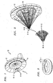
FIG. 2 is a ray tracing diagram illustrating the concentration of the reflected solar radiation for the solar concentrator ofFIG. 1 ; -
FIG. 3 illustrates a standard torus configuration, useful for understanding the spindle toroid geometry of the inventive solar reflectors; -
FIG. 4 is a front view of an exemplary outer reflector of the inventive solar concentrator, illustrating its keystone configuration; -
FIG. 5 is a front view of an exemplary inner reflector of the inventive solar concentrator, illustrating its keystone configuration; -
FIG. 6 is a front view of the concentric arrangement of the outer and inner reflectors, with the inner reflector disposed to overly the central region of the outer reflector; -
FIG. 7 illustrates the arrangement of a set of three separate petals from the outer reflector and their placement in creating the keystone configuration; -
FIG. 8 is an isometric view of a single petal from a reflector, showing its preferred monocoque construction; -
FIG. 9 is a rear view of the supporting structure for the solar concentrator of the present invention; -
FIG..10 is a side view of a Cassegrain type solar collection system using the solar concentrator of the present invention; and -
FIG. 11 is a top view of the system ofFIG 10 . -
FIG. 1 is an isometric view of an exemplarysolar concentrator 10 formed in accordance with the present invention. Unlike prior art solar concentrator arrangements based on creating "point" or "line" concentration of the solar radiation, the spindle toroid geometry of the inventive concentrator functions to direct the reflected solar into ring-like regions at the focal area F ofconcentrator 10. As mentioned above, the ring-like focal area provides a greater concentration of energy than the "line" focus associated with the prior art trough collectors, without requiring the expensive alignments associated with the prior art "point" focus associated with the prior art dish collectors. - In particular,
solar concentrator 10 is shown as comprising a pair of concentric reflectors including anouter reflector 12 and aninner reflector 14, where each reflector is formed of the spindle toroid geometry. As mentioned above, the use of a pair of reflectors is considered to be exemplary only, any suitable number of reflectors may be utilized to form a particular solar concentrator assembly. - Referring again to
FIG. 1 , the incoming solar energy reflected fromouter reflector 12 will be concentrated into a ring R-12 at focal area F, as shown, with the solar energy reflected frominner reflector 14 concentrated into a somewhat smaller ring R-14 at the same focal area F.FIG. 2 is a ray tracing diagram illustrating the concentration of the reflected solar radiation into rings R-12 and R-14, also showing an enlargement of rings R-12 and R-14 for the sake of clarity. By formingouter reflector 12 andinner reflector 14 of the preferred spindle toroid curvature, each one will independently reflect and focus the incoming light rays into a concentric ring configuration by separately delivering reflected beams at different locations as desired. - A standard torus is shown as a "tube" in
FIG. 3 and is defined by the following set of equations:


reflectors reflector 
- With this definition of the structure of each of
reflector FIGs. 1 and 2 illustrate this improvement in solar radiation concentration in accordance with the spindle toroid configuration ofreflectors solar concentrator 10 is part of a CPV system, HVAC system, industrial heat generation, electricity, or the like. The ability to concentrate the solar radiation into such a relatively small area with improved heat distribution by ring focus, and without the need for the expensive, "tight tolerance" optics of prior art solar collectors is considered to be a significant advantage of the arrangement of the present invention. - It is another significant aspect of the present invention that each
reflector solar concentrator 10 comprises a plurality of separate reflecting "petals", held in place in a keystone arrangement such that the final reflector structure is self-supporting. No additional bracing or support structure is required; this is considered to be a significant advance over prior art concentrator designs that required an extensive support mechanism which added to the weight and cost (as well as construction complexities) of the overall concentrator. Indeed, by eliminating the need for a support structure, the final solar concentrator structure is considerably lighter, easier to assemble on-site, and easier to maneuver than conventional solar collectors. -
FIGs. 4-6 particularly illustrate the keystone construction ofsolar concentrator 10, whereFIG. 4 is an isometric view ofouter reflector 12,FIG. 5 is an isometric view ofinner reflector 14, andFIG. 6 shows the concentric arrangement ofinner reflector 14 disposed to overlyouter reflector 12. As noted above, each reflector will separately concentrate the impinging radiation into a ring-like focal area (seeFIGs. 1 and6). FIG. 6 in particular illustrates the concentric arrangement ofsolar concentrator 10, withinner reflector 14 affixed to overly thecentral area 13 of outer reflector 12 (central area 13 is indicated by the dotted line inFIG. 4 ). -
FIG. 4 clearly illustrates the exemplary keystone configuration ofouter reflector 12, whereouter reflector 12 is shown as comprising a plurality of separate reflectingpetals 16. A set of reflecting petals 16-1, 16-2 and 16-3 ofreflector 12 is specifically referenced and shown as being disposed in a contiguous relationship, with the complete plurality ofpetals 16 disposed in a circular arrangement in the self-supporting keystone configuration. The exemplary embodiment ofouter reflector 12 shown inFIG. 4 is formed of sixteenseparate petals 16 and may be epoxied together, as discussed below, to formouter reflector 12. In one experimental design, a reflector of this geometry was shown to exhibit a clear aperture of 28.26m2. - A similar keystone configuration of
inner reflector 14 is shown inFIG. 5 , wherereflector 14 is shown as comprising a plurality of reflectingpetals 18. A set of reflecting petals 18-1, 18-2 and 18-3 ofinner reflector 14 is specifically illustrated inFIG. 5 . As withouter reflector 12, a set of sixteenindividual petals 18 is used to form this particular embodiment, epoxied together along their sides, to form the final arrangement as shown. A reflector of this geometry was found to exhibit a clear aperture of 14.13m2. - As noted above, the keystone configuration of each reflector in the solar concentrator of the present invention allows for adjacent petals to keep one another in place without additional fixturing.
FIG. 7 shows the set of three petals 16-1, 16-2 and 16-3, as they are begun to be placed side-by-side along a radius of curvature RC forouter reflector 12, radius RC dictated by the curvature of theindividual petals 16. An exemplary embodiment ofouter reflector 12 may exhibit a curvature on the order of 10.725, whileinner reflector 14 may have a slightly reduced curvature, on the order of 10.0. There is also presumed to be a unique relationship between the curvatures for outer andinner reflectors solar concentrator 10, as desired for various applications, while maintaining the optimal efficiency of light concentration (as well as directing desired wavelengths onto a receiver - which may comprise a number of PV cells). As stated above, the ability to formsolar concentrator 10 without other support structure significantly reduces the cost, weight and complexity of the final solar concentrator system. - In accordance with another aspect of the present invention, each reflecting
petal -
FIG. 8 is an isometric view of an exemplary monocoque-constructedpetal 16 fromouter reflector 12, whereelements 22 indicate exemplary locations where epoxy (or other suitable fixing material, including bolts or mechanical fixtures) may be disposed to allow for the plurality ofpetals 16 to be joined together to formouter reflector 12 without the use of any other mechanical support (i.e., the "keystone" configuration discussed above in association withFIGs. 4-7 ). By affixingreflective skin surface 20 to anunderlying support structure 25, the stresses experienced by anindividual petal 16 are uniformly disposed across the entire surface ofskin 20, allowing for the skin itself to be the load-bearing portion of the petal - the monocoque type of construction. -
Support structure 25 of eachpetal FIG. 8 , comprises atop brace 24, a pair of opposingsidewalls lower brace 30.FIG. 9 - a rear view of solar concentrator 10 - clearly illustrates eachpetal support structure 25 for the pluralities ofindividual petals - In accordance with the present invention,
mirror surface skin 20 is formed of a reflective material, preferably a material that is lightweight and relatively easy to replace when damaged or aged. Material choices forskin 20 include, but are not limited to, a passivated aluminum (or a layer of passivated aluminum disposed on the surface of another material), a highly reflective dielectric material, a polymer, an ultra-thin glass (e.g., 50 microns or less), or the like. Various alloys and/or surface finishes may be used to provide the desired degree of reflectivity on the skin for the solar concentrator of the present invention. - It is an advantage of the sectionalized structure of each reflector forming the inventive solar concentrator that if
skin surface 20 of a single petal is somehow damaged, a new sheet of appropriately-formed reflective material may simply be affixed to the surface of that petal. There is no need to dismantle the entire concentrator or remove the entire petal to solve the problem, as would be required for prior art arrangements.. - Further, the use of aluminum for the light-weight monocoque construction of
reflective skin surface 20 provides a significant advantage over the glass mirrors used in the conventional concentrators. In the conventional concentrators that use glass mirrors (which comprise of reflective surface coating such as silver nitrate and a glass cover to protect the reflective surface), the light beam suffers losses upon entering the protective glass as an incident beam and then upon exiting the glass as a reflected beam. By not requiring a glass cover, the present invention eliminates such loss of light and offers higher efficiency. - In accordance with the operation of the inventive solar concentrator, the concentric rings of concentrated solar radiation created at focal areas R-12 and R-14 (on the order of, for example, 40 or more suns) is thereafter utilized by a suitable receiver (such as a photovolatic (PV) device and/or a thermal device) to transform the solar radiation into electricity and/or heat. The specifics of the receiver design will be determined so as to best match the desired energy flux distribution across the focal area (i.e., the "rings"). As mentioned above, the ring-shaped beam offers larger surface area for heat transfer onto the receiver than the prior art "point-shaped" beam. It is considered that the ability to adaptively configure the sensitivity of the receiver to match the distribution of the energy flux will even more so improve the efficiency and economy of the inventive solar concentrator over those available in the prior art.
- One particular system for capturing and utilizing the concentrated solar radiation requires the use of an additional reflective surface to redirect the focused radiation (or at least a portion thereof) into an associated receiver. One advantage of using secondary reflection is that the receiver that may be more advantageously situated at a location (second focal region) other than initial focal area denoted by R-12 and R-14 (the first focal regions). This is useful because typically thermal or engine type of receivers are fairly heavy and therefore it is considered more practical to place this type of a receiver at the base. The used of a second focal region also allows for the concentrator assembly itself to be quickly and easily removed or repaired, without having to first disassemble a receiver component.
- A number of different kinds of secondary mirrors geometry and surfaces (such as glass, aluminum, dielectric) may be used. It is a significant additional aspect of the present invention to utilize a secondary mirror that consists of Cassegrain reflective surface. A Cassegrain mirror can be fabricated to allow 'application-specific' beam configuration to be reflected onto the receiver, typically located at the base of the concentrator system.
-
FIG. 10 is a side view of a solar collection system based onsolar concentrator 10, showing the use of an additional reflective surface along the optical axis where the incoming rays will be concentrated in their ring-like patterns. In particular, asecondary reflector 40 is disposed at this location and used to redirect the concentrated radiation into a receiver that may be located at a second focal region (for example, in thecenter area 14 of inner reflector 14). -
FIG. 11 is a "top view" of the arrangement ofFIG. 10 . This view clearly shows the curvatures and relationship betweensecondary reflector 40 and the pair ofspindle toroid reflectors solar concentrator 10.Secondary reflector 40 is shown as redirecting the incoming, focused and concentrated radiation into areceiver 15 located at (for example) the center ofinner reflector 14. - In addition to allowing for "application-specific" beam shaping, this Cassegrain-type arrangement of the present invention is particularly well-suited for situations where it is desired to extract multiple types of energy from the solar radiation, as described above. Indeed, it is possible, in accordance with one aspect of the present invention, to create both thermal and electrical outputs by directing the wavelengths (and frequencies) associated with the creation of electric energy into a PV cell array affixed at the secondary reflector, and directing the energy at the remaining wavelengths into a Stirling engine or other type of thermal receiver. That is, by incorporating a specific type of "notch" wavelength (frequency) filter at the focal area F, the different groupings of wavelengths may be directed into the proper receivers.
-
FIG. 11 showssecondary reflector 40 as being formed to include a "notch type"dielectric filter 60 disposed over the surface thereof.Dielectric filter 60 is fabricated to pass only the wavelengths associated with electrical energy creation, reflecting all other wavelengths associated toward receiver 15 (which is therefore configured as a thermal device). The wavelengths associated with the creation of electrical energy (e.g., 800-1200 nm) will pass throughdielectric filter 16 and impinge aPV cell array 17 disposed behindsecondary reflector 40. Thus, by covering the underlying surface ofreflector 40 withPV cells 17, the wavelengths passing throughfilter 40 can be efficiently used to create electrical energy. - By virtue of incorporating both types of receivers in the system, very little remaining solar energy will need to be eliminated. Various types of receivers may be arranged and designed to use in association with this and other embodiments of the present invention.
- While the invention has been described with regard to the preferred embodiments, it is to be understood by those skilled in the art that the invention is not limited thereof, and that changes and modifications may be made thereto without departing from the scope of the present invention as defined by the following claims.
Claims (14)
- A solar concentrator (10) comprising:one or more concentric solar reflectors (12, 14) comprising:∘ at least one outer solar reflector (12) with a central region (13); and∘ at least one inner solar reflector (14),
characterized in that
the at least one inner solar reflector (14) overlies the central region (13) of the at least one outer solar reflector (12),each of the at least one outer solar reflector (12) and each of the at least one inner solar reflector (14) is configured to create at the same focal area (F) one ring-like focal area(R-12, R-14);each of the at least one outer solar reflector (12) has a first spindle toroid geometry for directing first reflected solar radiation into said ring-like focal areas (R-12); andeach of the at least one inner solar reflector (14) has a second spindle toroid geometry for directing second reflected solar radiation into said ring-like focal areas (R-14). - The solar concentrator (10) of claim 1 wherein
each the at least one outer solar reflector (12) comprises one or more first separate petals (16) disposed in a first circular arrangement; and
each the at least one inner solar reflector (14) comprises one or more separate second petals (18) disposed in a second circular arrangement. - The solar concentrator (10) of claim 2 wherein
the one or more first separate petals (16) are in a first keystone arrangement; and
the one or more second separate petals (18) are in a second keystone arrangement. - The solar concentrator (10) of claim 2 wherein
each petal (16) of the one or more first separate petals has a monocoque construction;
the monocoque construction comprises a supporting structure (25) and a reflective skin surface (20) attached to the supporting structure (25); and
the reflective skin surface (20) is configured to support a load of torsional and bending stresses. - The solar concentrator (10) of claim 4 wherein the reflective skin surface (20) of the monocoque construction of each petal (16) of the one or more separate petals is removable and replaceable.
- The solar concentrator (10) of claim 4 or 5 wherein the supporting structure (25) of the monocoque construction of each petal (16) of the one or more separate petals comprises an aluminum material.
- The solar concentrator (10) of claim 4 or 5 wherein the reflective skin surface (20) of the monocoque construction of each petal (16) of the one or more separate petals comprises a material selected from: a first passivated aluminum layer, a second passivated aluminum layer disposed an a surface of another material, a highly reflective dielectric mate-rial, a polymer, or an ultra-thin glass layer.
- A solar energy collection system comprising
the solar concentrator (10) of claim 1; and
a receiver,
wherein the receiver is configured to convert the first solar radiation and the second solar radiation at the concentrated ring-like focal area (R-12, R-14) into at least one of electrical energy or thermal energy. - A solar energy collection system of claim 8 wherein the receiver is disposed at the focal area of the two or more concentric solar reflectors (12, 14).
- A solar energy collection system of claim 8 further comprising a secondary reflector (40) disposed at the focal area of the two or more of concentric solar reflectors (12, 14), wherein the secondary reflector (40) is configured to redirect at least a portion of the first solar radiation and a portion of the second solar radiation.
- A solar energy collection system of claim 10 wherein the secondary reflector (40) comprises a Cassegrain reflector.
- A solar energy collection system of claim 10, or 11 wherein the secondary reflector (40) further comprises a wavelength selective device (60) configured to direct first wavelengths of the first solar radiation and the second solar radiation into a photovoltaic cell array (17) and directing remaining wavelengths of the first solar radiation and the second solar radiation into a thermal energy receiver (15).
- A solar concentrator (10) of claim 2 or 3 wherein
each petal (18) of the one or more second separate petals has a monocoque construction;
the monocoque construction comprises a supporting structure and a reflective skin surface attached to the supporting structure; and
the reflective skin surface is configured to support a load of torsional and bending stresses. - The solar concentrator (10) of claim 1, 2, 3, 4, 5, 6, or 7 further comprising a receiver configured to convert the reflected solar radiation into at least one of electrical energy or thermal energy.
Priority Applications (1)
| Application Number | Priority Date | Filing Date | Title |
|---|---|---|---|
| EP15002855.3A EP3001120A1 (en) | 2009-07-24 | 2010-07-23 | Solar concentrator configuration with improved manufacturability and efficiency |
Applications Claiming Priority (3)
| Application Number | Priority Date | Filing Date | Title |
|---|---|---|---|
| US22844009P | 2009-07-24 | 2009-07-24 | |
| US12/841,266 US8680391B2 (en) | 2009-07-24 | 2010-07-22 | Solar concentrator configuration with improved manufacturability and efficiency |
| PCT/US2010/042987 WO2011011650A2 (en) | 2009-07-24 | 2010-07-23 | Solar concentrator configuration with improved manufacturabillty and efficiency |
Related Child Applications (1)
| Application Number | Title | Priority Date | Filing Date |
|---|---|---|---|
| EP15002855.3A Division EP3001120A1 (en) | 2009-07-24 | 2010-07-23 | Solar concentrator configuration with improved manufacturability and efficiency |
Publications (3)
| Publication Number | Publication Date |
|---|---|
| EP2457032A2 EP2457032A2 (en) | 2012-05-30 |
| EP2457032A4 EP2457032A4 (en) | 2014-05-21 |
| EP2457032B1 true EP2457032B1 (en) | 2015-10-07 |
Family
ID=43496228
Family Applications (3)
| Application Number | Title | Priority Date | Filing Date |
|---|---|---|---|
| EP15002855.3A Withdrawn EP3001120A1 (en) | 2009-07-24 | 2010-07-23 | Solar concentrator configuration with improved manufacturability and efficiency |
| EP10802930.7A Not-in-force EP2457032B1 (en) | 2009-07-24 | 2010-07-23 | Solar concentrator with improved manufacturabillty and efficiency |
| EP10802931.5A Withdrawn EP2457031A4 (en) | 2009-07-24 | 2010-07-23 | CALIBRATION SYSTEM FOR SOLAR COLLECTOR INSTALLATION |
Family Applications Before (1)
| Application Number | Title | Priority Date | Filing Date |
|---|---|---|---|
| EP15002855.3A Withdrawn EP3001120A1 (en) | 2009-07-24 | 2010-07-23 | Solar concentrator configuration with improved manufacturability and efficiency |
Family Applications After (1)
| Application Number | Title | Priority Date | Filing Date |
|---|---|---|---|
| EP10802931.5A Withdrawn EP2457031A4 (en) | 2009-07-24 | 2010-07-23 | CALIBRATION SYSTEM FOR SOLAR COLLECTOR INSTALLATION |
Country Status (10)
| Country | Link |
|---|---|
| US (5) | US8466400B2 (en) |
| EP (3) | EP3001120A1 (en) |
| CN (3) | CN102549350B (en) |
| BR (2) | BR112012001620A2 (en) |
| ES (1) | ES2552645T3 (en) |
| HK (2) | HK1214857A1 (en) |
| IN (2) | IN2012DN01338A (en) |
| MX (3) | MX349570B (en) |
| PT (1) | PT2457032E (en) |
| WO (2) | WO2011011651A2 (en) |
Families Citing this family (21)
| Publication number | Priority date | Publication date | Assignee | Title |
|---|---|---|---|---|
| IN2012DN02543A (en) * | 2009-09-23 | 2015-08-28 | Eagle Eye Res Inc | |
| US20110088684A1 (en) * | 2009-10-16 | 2011-04-21 | Raja Singh Tuli | Solar Energy Concentrator |
| US20140042296A1 (en) * | 2011-03-03 | 2014-02-13 | Aplicaciones Renovables Integradas, S.L. | Heliostat with a Drive Shaft Pointing at the Target, Reflection Sensor and a Closed-Loop Control System |
| FR2976917B1 (en) * | 2011-06-23 | 2013-06-28 | Thales Sa | HYBRID ASSEMBLY OF AT LEAST ONE SOLAR PANEL |
| US9482583B1 (en) * | 2011-10-06 | 2016-11-01 | Esolar, Inc. | Automated heliostat reflectivity measurement system |
| US9322437B2 (en) * | 2012-12-28 | 2016-04-26 | Sunpower Corporation | Support for solar energy collection |
| CN103062922B (en) * | 2013-01-28 | 2014-09-10 | 中国石油大学(华东) | Two-stage convergent solar energy concentrator system with decompressing and thermal stress reducing functions |
| CN103984360A (en) * | 2013-02-07 | 2014-08-13 | 浙江同景科技有限公司 | Sun-tracking four-quadrant measurement control system of disc-type solar thermal power generation system |
| US9279417B2 (en) * | 2013-04-26 | 2016-03-08 | Sol-Electrica, Llc | Solar power system |
| US9279416B2 (en) * | 2013-04-26 | 2016-03-08 | Sol-Electrica, Llc | Solar power system |
| JP5849191B2 (en) * | 2013-07-12 | 2016-01-27 | パナソニックIpマネジメント株式会社 | Condensing photoelectric conversion device |
| FR3013174B1 (en) * | 2013-11-14 | 2015-11-20 | Soitec Solar Gmbh | DEVICE FOR TESTING A CONCENTRATION PHOTOVOLTAIC MODULE |
| FR3013173B1 (en) | 2013-11-14 | 2017-05-12 | Soitec Solar Gmbh | METHOD FOR TESTING A CONCENTRATION PHOTOVOLTAIC MODULE |
| US11509264B2 (en) | 2014-05-22 | 2022-11-22 | Solar Cubed Holdings Llc | Full spectrum electro-magnetic energy system |
| CN105509339B (en) * | 2015-12-30 | 2017-06-06 | 哈尔滨工业大学 | A kind of scope of freedom Opticai Concentrating System With Secondary Reflection efficiently changed for solar heat/electricity |
| CN105972836B (en) * | 2016-05-24 | 2017-11-17 | 湖南科技大学 | A kind of quick focus adjustment method of solar energy dish-style concentrator mirror unit installation |
| CN108036527A (en) * | 2017-12-25 | 2018-05-15 | 天津清芸主力能源科技有限公司 | A kind of novel dish type optical collector structure |
| CN108518879A (en) * | 2018-04-09 | 2018-09-11 | 山西炅奇新能源科技有限公司 | A kind of focusing solar tracking control system, method and hot water preparation system |
| US11835265B2 (en) * | 2020-11-30 | 2023-12-05 | National Cheng Kung University | Apparatus combining solar tracker and dual heat source collector |
| USD1073590S1 (en) | 2022-10-03 | 2025-05-06 | James Curtis Godfrey | Solar and thermal mirror-cell panel |
| US20250020890A1 (en) * | 2023-07-14 | 2025-01-16 | Blueshift, LLC dba Outward Technologies | Lunar Articulating Mirror Array |
Family Cites Families (54)
| Publication number | Priority date | Publication date | Assignee | Title |
|---|---|---|---|---|
| US3267617A (en) * | 1962-08-22 | 1966-08-23 | Volk David | Lens generating apparatus |
| US3861379A (en) * | 1974-03-05 | 1975-01-21 | Jr Henry Anderson | Low profile solar ray concentrator |
| US3988166A (en) * | 1975-01-07 | 1976-10-26 | Beam Engineering, Inc. | Apparatus for enhancing the output of photovoltaic solar cells |
| US4148297A (en) * | 1976-07-08 | 1979-04-10 | Sherman Benjamin F Jr | Collector of direct dispersed and reflected waves |
| US4240406A (en) * | 1977-11-21 | 1980-12-23 | Solar Kinetics, Inc. | Solar reflector structure |
| US4161942A (en) * | 1977-12-27 | 1979-07-24 | Monk Robert J | Solar energy collector |
| US4146785A (en) * | 1978-02-13 | 1979-03-27 | Sunpower Systems Corporation | Sun-tracking control system for solar collector |
| US4215410A (en) * | 1979-02-09 | 1980-07-29 | Jerome H. Weslow | Solar tracker |
| US4348798A (en) * | 1979-10-19 | 1982-09-14 | Solar Kinetics, Inc. | Method of manufacturing solar collector module |
| US4314546A (en) * | 1980-01-21 | 1982-02-09 | Rca Corporation | Array positioning system |
| US4678292A (en) * | 1981-05-01 | 1987-07-07 | Rca Corporation | Curved structure and method for making same |
| JPS5813961A (en) * | 1981-07-18 | 1983-01-26 | Takashi Mori | Solar beam collector |
| US4548195A (en) * | 1983-12-27 | 1985-10-22 | Balhorn Alan C | Solar energy apparatus with automatic tracking alignment adjustments |
| US4611575A (en) * | 1984-03-07 | 1986-09-16 | Powell Roger A | Parabolic trough solar reflector |
| US4564275A (en) * | 1984-06-21 | 1986-01-14 | Mcdonnell Douglas Corporation | Automatic heliostat track alignment method |
| US4919527A (en) * | 1986-03-31 | 1990-04-24 | Nurmamed Saiylov | Solar radiation concentrator |
| US5002379A (en) * | 1989-04-12 | 1991-03-26 | Murtha R Michael | Bypass mirrors |
| US4947825A (en) * | 1989-09-11 | 1990-08-14 | Rockwell International Corporation | Solar concentrator - radiator assembly |
| US5934271A (en) * | 1994-07-19 | 1999-08-10 | Anutech Pty Limited | Large aperture solar collectors with improved stability |
| IL114261A0 (en) * | 1995-06-22 | 1995-10-31 | Yeda Res & Dev | System for control of heliostat field |
| KR970048612A (en) * | 1995-12-29 | 1997-07-29 | 김주용 | Solar Tracking System and Method Using Solar Array |
| US5882434A (en) * | 1996-10-15 | 1999-03-16 | United Solar Technologies, Inc. | Solar concentrator having an offset parabolic configuration |
| EP1174342A1 (en) * | 2000-07-20 | 2002-01-23 | Université de Liège | Solar concentrator |
| MXPA01000376A (en) * | 2001-01-11 | 2002-07-15 | Fernando Arcos Gomar Benjamin | Device for collecting and emitting radiations. |
| AUPR403901A0 (en) * | 2001-03-28 | 2001-04-26 | Solar Systems Pty Ltd | Solar tracking system |
| US6704607B2 (en) * | 2001-05-21 | 2004-03-09 | The Boeing Company | Method and apparatus for controllably positioning a solar concentrator |
| US6688303B2 (en) * | 2001-06-22 | 2004-02-10 | Science Applications International Corporation | Method and system for controlling operation of an energy conversion device |
| US6668820B2 (en) * | 2001-08-24 | 2003-12-30 | Solargenix Energy Llc | Multiple reflector solar concentrators and systems |
| US6680693B2 (en) * | 2002-03-07 | 2004-01-20 | The University Of Southern Mississippi | Method and apparatus for automatically tracking the sun with an object |
| AU2002950582A0 (en) * | 2002-08-05 | 2002-09-12 | Robert Edgar Whelan | Dish assembly |
| GR1005183B (en) * | 2003-04-02 | 2006-04-07 | �. ������ | Hybrid photovoltaic concentrating system with corrected total reflection reflectors for very large concentrating ratios |
| US6959993B2 (en) * | 2003-07-10 | 2005-11-01 | Energy Innovations, Inc. | Solar concentrator array with individually adjustable elements |
| US6988809B2 (en) * | 2004-01-16 | 2006-01-24 | Mario Rabinowitz | Advanced micro-optics solar energy collection system |
| US20060225582A1 (en) * | 2004-11-19 | 2006-10-12 | Uri Tasch | Apparatus and method for orienting rotatable objects |
| NZ555529A (en) * | 2004-12-03 | 2010-11-26 | Edo Dol | A reflector assembly for energy concentrators with an annular array of concentric reflective elements |
| DE102005018657A1 (en) * | 2005-04-21 | 2006-10-26 | Lokurlu, Ahmet, Dr. | Collector and collector assembly for recovering heat from incident radiation |
| US7858875B2 (en) * | 2005-09-29 | 2010-12-28 | Enfocus Engineering Corp. | Radiant energy conversion system |
| US7432488B1 (en) * | 2006-03-30 | 2008-10-07 | Energy Innovations, Inc. | Tracking solar collector with non-uniform solar cells and empirical tracking system including solar angle information |
| WO2007125867A1 (en) * | 2006-04-24 | 2007-11-08 | Sharp Kabushiki Kaisha | Photovoltaic power generation system and photovoltaic power generation system control method |
| US20070256725A1 (en) * | 2006-05-05 | 2007-11-08 | Palo Alto Research Center Incorporated | Solar Concentrating Photovoltaic Device With Resilient Cell Package Assembly |
| US7638708B2 (en) * | 2006-05-05 | 2009-12-29 | Palo Alto Research Center Incorporated | Laminated solar concentrating photovoltaic device |
| US20080029151A1 (en) * | 2006-08-07 | 2008-02-07 | Mcglynn Daniel | Terrestrial solar power system using III-V semiconductor solar cells |
| KR20090057242A (en) * | 2006-08-10 | 2009-06-04 | 업스트림 엔지니어링 오와이 | Lighting method and device |
| DE102006053758A1 (en) * | 2006-11-13 | 2008-05-15 | Deutsches Zentrum für Luft- und Raumfahrt e.V. | Method for controlling the alignment of a heliostat to a receiver, heliostat device and solar power plant |
| ES2534037T3 (en) * | 2007-03-30 | 2015-04-16 | Esolar, Inc. | System to direct incident radiation |
| US20080314438A1 (en) * | 2007-06-20 | 2008-12-25 | Alan Anthuan Tran | Integrated concentrator photovoltaics and water heater |
| US20090050191A1 (en) * | 2007-08-22 | 2009-02-26 | Sol Focus, Inc. | System and Method for Solar Tracking |
| US7645973B2 (en) * | 2007-10-15 | 2010-01-12 | Chien-Feng Lin | Sun-tracking power generating apparatus |
| US7501572B1 (en) * | 2007-12-31 | 2009-03-10 | Mario Rabinowitz | Solar photovoltaic cell system tracks the sun for increased efficiency |
| CN101266078B (en) * | 2008-04-29 | 2010-04-21 | 河海大学 | A heliostat tracking control device and control method thereof |
| US8253086B2 (en) * | 2008-07-03 | 2012-08-28 | Mh Solar Co., Ltd. | Polar mounting arrangement for a solar concentrator |
| TWI369470B (en) * | 2008-09-10 | 2012-08-01 | Sunplus Mmedia Inc | Solar tracking and concentration device |
| WO2012083383A1 (en) * | 2010-12-22 | 2012-06-28 | Commonwealth Scientific And Industrial Research Organisation | Heliostat calibration and control |
| TWI510749B (en) * | 2012-09-03 | 2015-12-01 | Atomic Energy Council | Solar tracking apparatus |
-
2010
- 2010-07-22 US US12/841,360 patent/US8466400B2/en not_active Expired - Fee Related
- 2010-07-22 US US12/841,266 patent/US8680391B2/en active Active - Reinstated
- 2010-07-23 MX MX2015003756A patent/MX349570B/en unknown
- 2010-07-23 EP EP15002855.3A patent/EP3001120A1/en not_active Withdrawn
- 2010-07-23 CN CN201080042707.9A patent/CN102549350B/en not_active Expired - Fee Related
- 2010-07-23 WO PCT/US2010/042991 patent/WO2011011651A2/en not_active Ceased
- 2010-07-23 ES ES10802930.7T patent/ES2552645T3/en active Active
- 2010-07-23 EP EP10802930.7A patent/EP2457032B1/en not_active Not-in-force
- 2010-07-23 IN IN1338DEN2012 patent/IN2012DN01338A/en unknown
- 2010-07-23 WO PCT/US2010/042987 patent/WO2011011650A2/en not_active Ceased
- 2010-07-23 PT PT108029307T patent/PT2457032E/en unknown
- 2010-07-23 MX MX2012001032A patent/MX2012001032A/en active IP Right Grant
- 2010-07-23 BR BR112012001620A patent/BR112012001620A2/en not_active IP Right Cessation
- 2010-07-23 BR BR112012001621A patent/BR112012001621A2/en not_active IP Right Cessation
- 2010-07-23 CN CN201080042186.7A patent/CN102575877B/en not_active Expired - Fee Related
- 2010-07-23 MX MX2012001033A patent/MX2012001033A/en active IP Right Grant
- 2010-07-23 IN IN1339DEN2012 patent/IN2012DN01339A/en unknown
- 2010-07-23 CN CN201510113289.2A patent/CN104913521A/en active Pending
- 2010-07-23 EP EP10802931.5A patent/EP2457031A4/en not_active Withdrawn
-
2013
- 2013-05-17 US US13/897,268 patent/US8937270B2/en active Active
-
2014
- 2014-02-26 US US14/190,946 patent/US9467089B2/en active Active
-
2015
- 2015-01-07 US US14/591,063 patent/US9312804B2/en active Active
-
2016
- 2016-03-09 HK HK16102722.3A patent/HK1214857A1/en unknown
- 2016-08-08 HK HK16109427.6A patent/HK1221280A1/en unknown
Also Published As
Similar Documents
| Publication | Publication Date | Title |
|---|---|---|
| US8680391B2 (en) | Solar concentrator configuration with improved manufacturability and efficiency | |
| US6384320B1 (en) | Solar compound concentrator of electric power generation system for residential homes | |
| US6668820B2 (en) | Multiple reflector solar concentrators and systems | |
| US6620995B2 (en) | Non-imaging system for radiant energy flux transformation | |
| CN103140723B (en) | Cross spider sexual type solar heat gathering-device | |
| US20130068285A1 (en) | Method and device for two-stage solar concentration and spectrum splitting based on dish concentration | |
| US20100206302A1 (en) | Rotational Trough Reflector Array For Solar-Electricity Generation | |
| TW200412410A (en) | Photovoltaic array module design for solar electric power generation systems | |
| AU2003259804A1 (en) | Concentrating solar energy receiver | |
| CN102422427A (en) | Solar concentrator | |
| US4150663A (en) | Solar energy collector and concentrator | |
| US20140048118A1 (en) | Solar energy systems using external reflectors | |
| US20030137754A1 (en) | Multistage system for radiant energy flux transformation | |
| JP2003149586A (en) | Condenser | |
| CN101203717A (en) | Collector and collector structure for obtaining heat from solar rays | |
| US20210254861A1 (en) | Solar thermal receivers with multi-scale light trapping geometry and features | |
| JP2003322419A (en) | Solar power concentrator for residential power generation system | |
| TWI232594B (en) | Stationary photovoltaic array module design for solar electric power generation systems | |
| KR100420868B1 (en) | Solar concentrator module | |
| KR101118478B1 (en) | Secondary concentrator for solar high concentration and easy changeable focal direction | |
| CN102971590A (en) | device for collecting solar energy | |
| KR101317361B1 (en) | Solar heat generator to use curved surface reflector | |
| CN119561480A (en) | A light-gathering and light-splitting system | |
| AU2002331695A1 (en) | Multiple reflector solar concentrators and systems |
Legal Events
| Date | Code | Title | Description |
|---|---|---|---|
| PUAI | Public reference made under article 153(3) epc to a published international application that has entered the european phase |
Free format text: ORIGINAL CODE: 0009012 |
|
| 17P | Request for examination filed |
Effective date: 20120224 |
|
| AK | Designated contracting states |
Kind code of ref document: A2 Designated state(s): AL AT BE BG CH CY CZ DE DK EE ES FI FR GB GR HR HU IE IS IT LI LT LU LV MC MK MT NL NO PL PT RO SE SI SK SM TR |
|
| DAX | Request for extension of the european patent (deleted) | ||
| REG | Reference to a national code |
Ref country code: HK Ref legal event code: DE Ref document number: 1170797 Country of ref document: HK |
|
| A4 | Supplementary search report drawn up and despatched |
Effective date: 20140424 |
|
| RIC1 | Information provided on ipc code assigned before grant |
Ipc: F24J 2/10 20060101ALI20140416BHEP Ipc: F24J 2/18 20060101AFI20140416BHEP |
|
| GRAP | Despatch of communication of intention to grant a patent |
Free format text: ORIGINAL CODE: EPIDOSNIGR1 |
|
| INTG | Intention to grant announced |
Effective date: 20150326 |
|
| RIN1 | Information on inventor provided before grant (corrected) |
Inventor name: FANGMAN, JOHN STEWART Inventor name: FANGMAN, JOHN MATHEW Inventor name: NETI, SUDHAKAR Inventor name: SHAH-YUKICH, ARATI Inventor name: FANGMAN, MICHAEL E. |
|
| GRAS | Grant fee paid |
Free format text: ORIGINAL CODE: EPIDOSNIGR3 |
|
| GRAA | (expected) grant |
Free format text: ORIGINAL CODE: 0009210 |
|
| AK | Designated contracting states |
Kind code of ref document: B1 Designated state(s): AL AT BE BG CH CY CZ DE DK EE ES FI FR GB GR HR HU IE IS IT LI LT LU LV MC MK MT NL NO PL PT RO SE SI SK SM TR |
|
| REG | Reference to a national code |
Ref country code: GB Ref legal event code: FG4D |
|
| REG | Reference to a national code |
Ref country code: AT Ref legal event code: REF Ref document number: 753995 Country of ref document: AT Kind code of ref document: T Effective date: 20151015 Ref country code: CH Ref legal event code: EP |
|
| REG | Reference to a national code |
Ref country code: IE Ref legal event code: FG4D |
|
| REG | Reference to a national code |
Ref country code: CH Ref legal event code: NV Representative=s name: FELBER AND PARTNER AG, CH Ref country code: CH Ref legal event code: PCOW Free format text: NEW ADDRESS: 1041 BERN ROAD, WYOMISSING PA 19610 (US) |
|
| REG | Reference to a national code |
Ref country code: DE Ref legal event code: R096 Ref document number: 602010028115 Country of ref document: DE |
|
| REG | Reference to a national code |
Ref country code: DE Ref legal event code: R082 Ref document number: 602010028115 Country of ref document: DE Representative=s name: PATENTANWAELTE STREHL, SCHUEBEL-HOPF & PARTNER, DE Ref country code: DE Ref legal event code: R081 Ref document number: 602010028115 Country of ref document: DE Owner name: CEWA TECHNOLOGIES, INC., WYOMISSING, US Free format text: FORMER OWNER: CEWA TECHNOLOGIES, INC., BETHLEHEM, PA., US Ref country code: DE Ref legal event code: R082 Ref document number: 602010028115 Country of ref document: DE Representative=s name: STREHL SCHUEBEL-HOPF & PARTNER MBB PATENTANWAE, DE |
|
| REG | Reference to a national code |
Ref country code: ES Ref legal event code: FG2A Ref document number: 2552645 Country of ref document: ES Kind code of ref document: T3 Effective date: 20151201 |
|
| REG | Reference to a national code |
Ref country code: PT Ref legal event code: SC4A Free format text: AVAILABILITY OF NATIONAL TRANSLATION Effective date: 20151209 |
|
| REG | Reference to a national code |
Ref country code: NL Ref legal event code: MP Effective date: 20151007 |
|
| REG | Reference to a national code |
Ref country code: LT Ref legal event code: MG4D |
|
| REG | Reference to a national code |
Ref country code: HK Ref legal event code: GR Ref document number: 1170797 Country of ref document: HK |
|
| PG25 | Lapsed in a contracting state [announced via postgrant information from national office to epo] |
Ref country code: NL Free format text: LAPSE BECAUSE OF FAILURE TO SUBMIT A TRANSLATION OF THE DESCRIPTION OR TO PAY THE FEE WITHIN THE PRESCRIBED TIME-LIMIT Effective date: 20151007 Ref country code: HR Free format text: LAPSE BECAUSE OF FAILURE TO SUBMIT A TRANSLATION OF THE DESCRIPTION OR TO PAY THE FEE WITHIN THE PRESCRIBED TIME-LIMIT Effective date: 20151007 Ref country code: IS Free format text: LAPSE BECAUSE OF FAILURE TO SUBMIT A TRANSLATION OF THE DESCRIPTION OR TO PAY THE FEE WITHIN THE PRESCRIBED TIME-LIMIT Effective date: 20160207 Ref country code: NO Free format text: LAPSE BECAUSE OF FAILURE TO SUBMIT A TRANSLATION OF THE DESCRIPTION OR TO PAY THE FEE WITHIN THE PRESCRIBED TIME-LIMIT Effective date: 20160107 Ref country code: LT Free format text: LAPSE BECAUSE OF FAILURE TO SUBMIT A TRANSLATION OF THE DESCRIPTION OR TO PAY THE FEE WITHIN THE PRESCRIBED TIME-LIMIT Effective date: 20151007 |
|
| PG25 | Lapsed in a contracting state [announced via postgrant information from national office to epo] |
Ref country code: PL Free format text: LAPSE BECAUSE OF FAILURE TO SUBMIT A TRANSLATION OF THE DESCRIPTION OR TO PAY THE FEE WITHIN THE PRESCRIBED TIME-LIMIT Effective date: 20151007 Ref country code: LV Free format text: LAPSE BECAUSE OF FAILURE TO SUBMIT A TRANSLATION OF THE DESCRIPTION OR TO PAY THE FEE WITHIN THE PRESCRIBED TIME-LIMIT Effective date: 20151007 Ref country code: SE Free format text: LAPSE BECAUSE OF FAILURE TO SUBMIT A TRANSLATION OF THE DESCRIPTION OR TO PAY THE FEE WITHIN THE PRESCRIBED TIME-LIMIT Effective date: 20151007 Ref country code: FI Free format text: LAPSE BECAUSE OF FAILURE TO SUBMIT A TRANSLATION OF THE DESCRIPTION OR TO PAY THE FEE WITHIN THE PRESCRIBED TIME-LIMIT Effective date: 20151007 |
|
| REG | Reference to a national code |
Ref country code: GR Ref legal event code: EP Ref document number: 20150402474 Country of ref document: GR Effective date: 20160201 |
|
| REG | Reference to a national code |
Ref country code: DE Ref legal event code: R097 Ref document number: 602010028115 Country of ref document: DE |
|
| REG | Reference to a national code |
Ref country code: FR Ref legal event code: PLFP Year of fee payment: 7 |
|
| PG25 | Lapsed in a contracting state [announced via postgrant information from national office to epo] |
Ref country code: CZ Free format text: LAPSE BECAUSE OF FAILURE TO SUBMIT A TRANSLATION OF THE DESCRIPTION OR TO PAY THE FEE WITHIN THE PRESCRIBED TIME-LIMIT Effective date: 20151007 |
|
| PLBE | No opposition filed within time limit |
Free format text: ORIGINAL CODE: 0009261 |
|
| STAA | Information on the status of an ep patent application or granted ep patent |
Free format text: STATUS: NO OPPOSITION FILED WITHIN TIME LIMIT |
|
| PG25 | Lapsed in a contracting state [announced via postgrant information from national office to epo] |
Ref country code: RO Free format text: LAPSE BECAUSE OF FAILURE TO SUBMIT A TRANSLATION OF THE DESCRIPTION OR TO PAY THE FEE WITHIN THE PRESCRIBED TIME-LIMIT Effective date: 20151007 Ref country code: DK Free format text: LAPSE BECAUSE OF FAILURE TO SUBMIT A TRANSLATION OF THE DESCRIPTION OR TO PAY THE FEE WITHIN THE PRESCRIBED TIME-LIMIT Effective date: 20151007 Ref country code: SM Free format text: LAPSE BECAUSE OF FAILURE TO SUBMIT A TRANSLATION OF THE DESCRIPTION OR TO PAY THE FEE WITHIN THE PRESCRIBED TIME-LIMIT Effective date: 20151007 Ref country code: SK Free format text: LAPSE BECAUSE OF FAILURE TO SUBMIT A TRANSLATION OF THE DESCRIPTION OR TO PAY THE FEE WITHIN THE PRESCRIBED TIME-LIMIT Effective date: 20151007 Ref country code: EE Free format text: LAPSE BECAUSE OF FAILURE TO SUBMIT A TRANSLATION OF THE DESCRIPTION OR TO PAY THE FEE WITHIN THE PRESCRIBED TIME-LIMIT Effective date: 20151007 |
|
| 26N | No opposition filed |
Effective date: 20160708 |
|
| PG25 | Lapsed in a contracting state [announced via postgrant information from national office to epo] |
Ref country code: SI Free format text: LAPSE BECAUSE OF FAILURE TO SUBMIT A TRANSLATION OF THE DESCRIPTION OR TO PAY THE FEE WITHIN THE PRESCRIBED TIME-LIMIT Effective date: 20151007 |
|
| PG25 | Lapsed in a contracting state [announced via postgrant information from national office to epo] |
Ref country code: BE Free format text: LAPSE BECAUSE OF FAILURE TO SUBMIT A TRANSLATION OF THE DESCRIPTION OR TO PAY THE FEE WITHIN THE PRESCRIBED TIME-LIMIT Effective date: 20151007 |
|
| PG25 | Lapsed in a contracting state [announced via postgrant information from national office to epo] |
Ref country code: MC Free format text: LAPSE BECAUSE OF FAILURE TO SUBMIT A TRANSLATION OF THE DESCRIPTION OR TO PAY THE FEE WITHIN THE PRESCRIBED TIME-LIMIT Effective date: 20151007 |
|
| REG | Reference to a national code |
Ref country code: IE Ref legal event code: MM4A |
|
| REG | Reference to a national code |
Ref country code: FR Ref legal event code: PLFP Year of fee payment: 8 |
|
| PG25 | Lapsed in a contracting state [announced via postgrant information from national office to epo] |
Ref country code: IE Free format text: LAPSE BECAUSE OF NON-PAYMENT OF DUE FEES Effective date: 20160723 |
|
| PG25 | Lapsed in a contracting state [announced via postgrant information from national office to epo] |
Ref country code: LU Free format text: LAPSE BECAUSE OF NON-PAYMENT OF DUE FEES Effective date: 20160723 |
|
| PGFP | Annual fee paid to national office [announced via postgrant information from national office to epo] |
Ref country code: ES Payment date: 20170818 Year of fee payment: 8 Ref country code: FR Payment date: 20170727 Year of fee payment: 8 Ref country code: DE Payment date: 20170915 Year of fee payment: 8 Ref country code: GB Payment date: 20170727 Year of fee payment: 8 Ref country code: IT Payment date: 20170721 Year of fee payment: 8 Ref country code: CH Payment date: 20170727 Year of fee payment: 8 Ref country code: GR Payment date: 20170725 Year of fee payment: 8 |
|
| REG | Reference to a national code |
Ref country code: DE Ref legal event code: R079 Ref document number: 602010028115 Country of ref document: DE Free format text: PREVIOUS MAIN CLASS: F24J0002180000 Ipc: F24S0023790000 |
|
| PGFP | Annual fee paid to national office [announced via postgrant information from national office to epo] |
Ref country code: PT Payment date: 20170823 Year of fee payment: 8 Ref country code: AT Payment date: 20170728 Year of fee payment: 8 |
|
| PG25 | Lapsed in a contracting state [announced via postgrant information from national office to epo] |
Ref country code: CY Free format text: LAPSE BECAUSE OF FAILURE TO SUBMIT A TRANSLATION OF THE DESCRIPTION OR TO PAY THE FEE WITHIN THE PRESCRIBED TIME-LIMIT Effective date: 20151007 Ref country code: HU Free format text: LAPSE BECAUSE OF FAILURE TO SUBMIT A TRANSLATION OF THE DESCRIPTION OR TO PAY THE FEE WITHIN THE PRESCRIBED TIME-LIMIT; INVALID AB INITIO Effective date: 20100723 |
|
| PG25 | Lapsed in a contracting state [announced via postgrant information from national office to epo] |
Ref country code: MK Free format text: LAPSE BECAUSE OF FAILURE TO SUBMIT A TRANSLATION OF THE DESCRIPTION OR TO PAY THE FEE WITHIN THE PRESCRIBED TIME-LIMIT Effective date: 20151007 Ref country code: TR Free format text: LAPSE BECAUSE OF FAILURE TO SUBMIT A TRANSLATION OF THE DESCRIPTION OR TO PAY THE FEE WITHIN THE PRESCRIBED TIME-LIMIT Effective date: 20151007 Ref country code: MT Free format text: LAPSE BECAUSE OF NON-PAYMENT OF DUE FEES Effective date: 20160731 |
|
| PG25 | Lapsed in a contracting state [announced via postgrant information from national office to epo] |
Ref country code: BG Free format text: LAPSE BECAUSE OF FAILURE TO SUBMIT A TRANSLATION OF THE DESCRIPTION OR TO PAY THE FEE WITHIN THE PRESCRIBED TIME-LIMIT Effective date: 20151007 |
|
| PG25 | Lapsed in a contracting state [announced via postgrant information from national office to epo] |
Ref country code: AL Free format text: LAPSE BECAUSE OF FAILURE TO SUBMIT A TRANSLATION OF THE DESCRIPTION OR TO PAY THE FEE WITHIN THE PRESCRIBED TIME-LIMIT Effective date: 20151007 |
|
| REG | Reference to a national code |
Ref country code: DE Ref legal event code: R119 Ref document number: 602010028115 Country of ref document: DE |
|
| REG | Reference to a national code |
Ref country code: CH Ref legal event code: PL |
|
| REG | Reference to a national code |
Ref country code: AT Ref legal event code: MM01 Ref document number: 753995 Country of ref document: AT Kind code of ref document: T Effective date: 20180723 |
|
| GBPC | Gb: european patent ceased through non-payment of renewal fee |
Effective date: 20180723 |
|
| PG25 | Lapsed in a contracting state [announced via postgrant information from national office to epo] |
Ref country code: AT Free format text: LAPSE BECAUSE OF NON-PAYMENT OF DUE FEES Effective date: 20180723 Ref country code: LI Free format text: LAPSE BECAUSE OF NON-PAYMENT OF DUE FEES Effective date: 20180731 Ref country code: GB Free format text: LAPSE BECAUSE OF NON-PAYMENT OF DUE FEES Effective date: 20180723 Ref country code: FR Free format text: LAPSE BECAUSE OF NON-PAYMENT OF DUE FEES Effective date: 20180731 Ref country code: DE Free format text: LAPSE BECAUSE OF NON-PAYMENT OF DUE FEES Effective date: 20190201 Ref country code: CH Free format text: LAPSE BECAUSE OF NON-PAYMENT OF DUE FEES Effective date: 20180731 |
|
| PG25 | Lapsed in a contracting state [announced via postgrant information from national office to epo] |
Ref country code: GR Free format text: LAPSE BECAUSE OF NON-PAYMENT OF DUE FEES Effective date: 20190207 Ref country code: PT Free format text: LAPSE BECAUSE OF NON-PAYMENT OF DUE FEES Effective date: 20190123 |
|
| REG | Reference to a national code |
Ref country code: AT Ref legal event code: UEP Ref document number: 753995 Country of ref document: AT Kind code of ref document: T Effective date: 20151007 |
|
| PG25 | Lapsed in a contracting state [announced via postgrant information from national office to epo] |
Ref country code: IT Free format text: LAPSE BECAUSE OF NON-PAYMENT OF DUE FEES Effective date: 20180723 |
|
| REG | Reference to a national code |
Ref country code: ES Ref legal event code: FD2A Effective date: 20190917 |
|
| PG25 | Lapsed in a contracting state [announced via postgrant information from national office to epo] |
Ref country code: ES Free format text: LAPSE BECAUSE OF NON-PAYMENT OF DUE FEES Effective date: 20180724 |