EP2456964B1 - Muffler attachment system - Google Patents
Muffler attachment system Download PDFInfo
- Publication number
- EP2456964B1 EP2456964B1 EP10737163.5A EP10737163A EP2456964B1 EP 2456964 B1 EP2456964 B1 EP 2456964B1 EP 10737163 A EP10737163 A EP 10737163A EP 2456964 B1 EP2456964 B1 EP 2456964B1
- Authority
- EP
- European Patent Office
- Prior art keywords
- engine
- muffler
- intake pipe
- exhaust port
- housing
- Prior art date
- Legal status (The legal status is an assumption and is not a legal conclusion. Google has not performed a legal analysis and makes no representation as to the accuracy of the status listed.)
- Active
Links
Images




Classifications
-
- F—MECHANICAL ENGINEERING; LIGHTING; HEATING; WEAPONS; BLASTING
- F01—MACHINES OR ENGINES IN GENERAL; ENGINE PLANTS IN GENERAL; STEAM ENGINES
- F01N—GAS-FLOW SILENCERS OR EXHAUST APPARATUS FOR MACHINES OR ENGINES IN GENERAL; GAS-FLOW SILENCERS OR EXHAUST APPARATUS FOR INTERNAL-COMBUSTION ENGINES
- F01N13/00—Exhaust or silencing apparatus characterised by constructional features
- F01N13/002—Apparatus adapted for particular uses, e.g. for portable devices driven by machines or engines
-
- F—MECHANICAL ENGINEERING; LIGHTING; HEATING; WEAPONS; BLASTING
- F01—MACHINES OR ENGINES IN GENERAL; ENGINE PLANTS IN GENERAL; STEAM ENGINES
- F01N—GAS-FLOW SILENCERS OR EXHAUST APPARATUS FOR MACHINES OR ENGINES IN GENERAL; GAS-FLOW SILENCERS OR EXHAUST APPARATUS FOR INTERNAL-COMBUSTION ENGINES
- F01N1/00—Silencing apparatus characterised by method of silencing
- F01N1/08—Silencing apparatus characterised by method of silencing by reducing exhaust energy by throttling or whirling
-
- F—MECHANICAL ENGINEERING; LIGHTING; HEATING; WEAPONS; BLASTING
- F01—MACHINES OR ENGINES IN GENERAL; ENGINE PLANTS IN GENERAL; STEAM ENGINES
- F01N—GAS-FLOW SILENCERS OR EXHAUST APPARATUS FOR MACHINES OR ENGINES IN GENERAL; GAS-FLOW SILENCERS OR EXHAUST APPARATUS FOR INTERNAL-COMBUSTION ENGINES
- F01N13/00—Exhaust or silencing apparatus characterised by constructional features
- F01N13/18—Construction facilitating manufacture, assembly, or disassembly
- F01N13/1805—Fixing exhaust manifolds, exhaust pipes or pipe sections to each other, to engine or to vehicle body
-
- F—MECHANICAL ENGINEERING; LIGHTING; HEATING; WEAPONS; BLASTING
- F01—MACHINES OR ENGINES IN GENERAL; ENGINE PLANTS IN GENERAL; STEAM ENGINES
- F01N—GAS-FLOW SILENCERS OR EXHAUST APPARATUS FOR MACHINES OR ENGINES IN GENERAL; GAS-FLOW SILENCERS OR EXHAUST APPARATUS FOR INTERNAL-COMBUSTION ENGINES
- F01N13/00—Exhaust or silencing apparatus characterised by constructional features
- F01N13/18—Construction facilitating manufacture, assembly, or disassembly
- F01N13/1805—Fixing exhaust manifolds, exhaust pipes or pipe sections to each other, to engine or to vehicle body
- F01N13/1811—Fixing exhaust manifolds, exhaust pipes or pipe sections to each other, to engine or to vehicle body with means permitting relative movement, e.g. compensation of thermal expansion or vibration
-
- F—MECHANICAL ENGINEERING; LIGHTING; HEATING; WEAPONS; BLASTING
- F01—MACHINES OR ENGINES IN GENERAL; ENGINE PLANTS IN GENERAL; STEAM ENGINES
- F01N—GAS-FLOW SILENCERS OR EXHAUST APPARATUS FOR MACHINES OR ENGINES IN GENERAL; GAS-FLOW SILENCERS OR EXHAUST APPARATUS FOR INTERNAL-COMBUSTION ENGINES
- F01N13/00—Exhaust or silencing apparatus characterised by constructional features
- F01N13/18—Construction facilitating manufacture, assembly, or disassembly
- F01N13/1838—Construction facilitating manufacture, assembly, or disassembly characterised by the type of connection between parts of exhaust or silencing apparatus, e.g. between housing and tubes, between tubes and baffles
- F01N13/1844—Mechanical joints
- F01N13/1855—Mechanical joints the connection being realised by using bolts, screws, rivets or the like
-
- F—MECHANICAL ENGINEERING; LIGHTING; HEATING; WEAPONS; BLASTING
- F01—MACHINES OR ENGINES IN GENERAL; ENGINE PLANTS IN GENERAL; STEAM ENGINES
- F01N—GAS-FLOW SILENCERS OR EXHAUST APPARATUS FOR MACHINES OR ENGINES IN GENERAL; GAS-FLOW SILENCERS OR EXHAUST APPARATUS FOR INTERNAL-COMBUSTION ENGINES
- F01N2590/00—Exhaust or silencing apparatus adapted to particular use, e.g. for military applications, airplanes, submarines
- F01N2590/06—Exhaust or silencing apparatus adapted to particular use, e.g. for military applications, airplanes, submarines for hand-held tools or portables devices
Definitions
- the present invention relates generally to the field of combustion engines. More specifically the present invention relates to a system for attaching a muffler to a combustion engine configured for use with power equipment, such as lawn mowers, pressure washers, secondary generators, and the like.
- combustion engines are typically equipped with mufflers to reduce noise emissions.
- the muffler on a small engine is typically attached directly to the exhaust outlet of the cylinder block or cylinder head, and includes a resonating chamber or chambers designed to dissipate sound.
- Some mufflers include perforations on the housing for exhaust gases to exit, while others include an outlet tube.
- exhaust gases and noise enter the muffler through a conduit attached to the cylinder block.
- the noise is directed into a resonating chamber, where the noise is dissipated.
- the chamber walls are formed from the muffler housing and internal separators or baffles.
- the separators are perforated, such that exhaust gases and noise pass through the perforations into another chamber of the muffler, where the noise is further dissipated. Exhaust gases exit the muffler through the outlet tube.
- Other mufflers use a perforate outlet formed from a series of perforations in the muffler housing.
- US3863734 discloses a muffler having a tub shaped body and a cover with mating flanges sealed and secured together by crimping the flanges to provide a closed dog-legged muffler chamber.
- One embodiment of the invention relates to an engine including an exhaust conduit.
- the exhaust conduit has an exhaust port on an end of the exhaust conduit.
- the exhaust conduit has an angled inside surface that has a cross section that widens toward the exhaust port.
- the engine further includes a muffler having a housing with an intake pipe. The intake pipe is inserted through the exhaust port such that the intake pipe is wedged into the angled inside surface of the exhaust conduit.
- the muffler for an internal combustion engine.
- the muffler includes a housing that forms an intake and an outlet of the muffler.
- the muffler includes an outwardly extending conduit connected to the housing.
- the conduit is designed to be inserted into an exhaust port of an engine.
- the muffler further includes a flexible portion of the housing. Upon attachment of the muffler to the engine, a compression force is stored via elastic deflection of the flexible portion.
- the engine 110 further includes a crankcase 120 and a sump 122 fastened to the underside of the crankcase 120.
- the crankcase 120 supports internal components of the engine 110, such as a piston, a connecting rod, a camshaft, and other components.
- the sump 122 forms a base of the crankcase 120, and holds a pool of oil lubricant within the crankcase 120.
- a vertical crankshaft 124 extends from the crankcase 120, through the sump 122, and may be used to drive power equipment, such as a rotary lawn mower, a pressure washer pump, a secondary generator, or other equipment.
- the engine may include a horizontal crankshaft, an automatic starter, and the crankcase 120 and sump 122 may be integrally cast.
- FIG. 2 shows a side view of the engine 110, with various engine components not shown to better display the engine 110 structure.
- the blower housing 112 is omitted to show components on the top of the engine 110, including a base 130 of a blower scroll, an ignition armature 132, and a rocker cover 118.
- the base 130 guides air from a blower fan to cool parts of the engine 110 heated as a result of the combustion process.
- the ignition armature 132 produces a timed electric charge used by a spark plug 144 to ignite the fuel.
- the rocker cover 118 is mounted to a side of the engine 110, and encases rockers 138 (see FIG. 5 ) that drive intake and exhaust valves. Beneath the rocker cover 118 and rockers 138 is a cylinder head 142 covering a cylinder block 140. The cylinder head 142 caps the cylinder block 140, forming a combustion chamber. Intake and exhaust valves are controlled by the rockers, and control the flow of air in and exhaust out of the combustion chamber.
- a muffler 128 is attached to a side of the engine 110.
- the muffler 128 reduces noise emissions from combustion processes occurring within the engine 110.
- the muffler 128 includes a housing 136 having a generally rectangular body formed from two shells crimped together. In other embodiments, the body may be generally circular, square, octagonal, or other shapes.
- the housing 136 includes mounting apertures 156, with the muffler 128 fastened to the cylinder head 142 with fasteners 134 extending through the mounting apertures 156.
- In the center of the muffler 128 are a series of perforations 160 on the housing 136. Exhaust gases exit the muffler 128 through the perforations 160.
- the perforations 160 of the outlet are not in the center of the muffler housing.
- the muffler outlet includes a tube through which exhaust gases exit. Muffler geometries and dimensions vary depending upon the particular frequency and amplitude of sound to be dissipated and other factors, such as an intended application.
- the engine 110 is a four-stroke engine.
- An exhaust conduit 150 extends within the cylinder head 142. In other embodiments the exhaust conduit extends within the cylinder block 140. The exhaust gases exit the cylinder head 142 through the exhaust port 146, and into the muffler 128.
- FIG. 4 shows an exploded view of the cylinder head 142 and the muffler 128, with fasteners 134 (e.g., screws, bolts, etc.) for attaching the muffler 128 to the cylinder head 142.
- fasteners 134 e.g., screws, bolts, etc.
- FIGS. 2 and 4 show that the fasteners 134 pass through the apertures 156 in a flat portion 152 along an edge 154 of the muffler housing 136.
- Use of the flat portion 152 along the edge 154 reduces the surface area of the interface between the fasteners 134 and the muffler 128, further reducing heat transfer to the fasteners 134.
- the exhaust conduit 150 is shown extending within the cylinder head 142 to the intake pipe 168 of the muffler 128.
- the exhaust conduit 150 is chamfered proximate to where the exhaust conduit 150 contacts the intake pipe 168 of the muffler 128.
- Exhaust gases entering the muffler 128 enter a first resonance chamber 172.
- One side of the chamber 172 is formed from a separator 174 (or baffle) within the muffler 128.
- the separator includes a dome-like structure 176.
- the other sides of the chamber 172 are formed from the housing 136. Exhaust gases pass from the first chamber 172 through a series of perforations in the separator 174, into a second chamber 178. As shown in FIGS.
- Engine noise is dissipated in the first chamber 172, and further dissipated in the second chamber 178.
- Other embodiments include mufflers with different numbers of chambers and separators.
- a spark arrester may be coupled to the end of the tube.
- the intake pipe 168 of the muffler is tapered.
- the cross-sectional area of the intake pipe 168 decreases with distance away from the muffler 128.
- the rate of decrease is linear, while in other embodiments, the rate of decrease is non-linear and not continuous.
- the intake pipe 168 is inserted into the exhaust port 146, such that the end of the intake pipe 168 contacts chamfered walls of the exhaust conduit 150.
- the intake pipe 168 When the engine 110 is running, heat transfers from hot exhaust gases passing through the exhaust conduit 150 and into engine components, such as the intake pipe 168 of the muffler 128.
- the engine components expand, with different materials expanding at different rates and to different extents.
- the intake pipe 168 is designed so that thermal expansion of the materials will improve the seal between the intake pipe 168 and the exhaust conduit 150.
- FIGS. 7A , 7B, and 7C show a muffler 210 according to another exemplary embodiment.
- the muffler 210 is formed from a front shell 212 and a back shell 214 crimped together around edges 216.
- the front shell 212 includes an intake pipe 218 extending outward from the front shell 212.
- the angle of taper ⁇ ' of the intake pipe 218 is less than a chamfer angle ⁇ " of the exhaust conduit 224.
- the difference of relative angles ⁇ ', ⁇ " is approximately between two to twenty degrees, preferably between five to ten degrees, such as about seven degrees. A meeting of two angled surfaces is intended to increase the surface area of the contact 226, producing a better seal.
- FIG. 8A shows a fitting arrangement 310, with an intake 312 of a muffler and an exhaust port 314 of an engine.
- the intake 312 includes an intake pipe 318 having a uniform cross-section.
- the exhaust port 314 is formed at the end of an exhaust conduit 320.
- the exhaust conduit 320 has a chamfered portion 322 with a widening cross-sectional area leading to the exhaust port 314.
- the intake pipe 318 may be inserted into the chamfered portion 322, where an end of the intake pipe 318 contacts walls of the exhaust conduit 320. As the intake pipe 318 is inserted, some of the insertion force compresses an interface between the intake pipe 318 and the chamfered portion 322, producing an airtight seal.
- FIG. 8B shows a fitting arrangement 510, with an intake 512 of a muffler and an exhaust port 514 of an engine.
- the intake 512 includes an intake pipe 516 having a rounded end 518 with a cross-sectional area narrowing away from the muffler. In some embodiments, the rate of narrowing is not constant.
- the exhaust port 514 is formed at the end of an exhaust conduit 520.
- the exhaust conduit 520 has a cross-sectional area that widens away from the engine. In some embodiments, the rate of widening is not constant.
- the exhaust conduit 520 further includes a step 522 that serves has a backstop to limit a distance of insertion of the intake pipe 516 into the exhaust conduit 520.
Landscapes
- Engineering & Computer Science (AREA)
- Chemical & Material Sciences (AREA)
- Combustion & Propulsion (AREA)
- Mechanical Engineering (AREA)
- General Engineering & Computer Science (AREA)
- Exhaust Silencers (AREA)
Description
- The present invention relates generally to the field of combustion engines. More specifically the present invention relates to a system for attaching a muffler to a combustion engine configured for use with power equipment, such as lawn mowers, pressure washers, secondary generators, and the like.
- The combustion process associated with internal combustion engines can be quite loud. As such, combustion engines are typically equipped with mufflers to reduce noise emissions. The muffler on a small engine is typically attached directly to the exhaust outlet of the cylinder block or cylinder head, and includes a resonating chamber or chambers designed to dissipate sound. Some mufflers include perforations on the housing for exhaust gases to exit, while others include an outlet tube.
- In a typical multiple-chambered, tube-outlet muffler for a small combustion engine, exhaust gases and noise enter the muffler through a conduit attached to the cylinder block. The noise is directed into a resonating chamber, where the noise is dissipated. Typically, the chamber walls are formed from the muffler housing and internal separators or baffles. The separators are perforated, such that exhaust gases and noise pass through the perforations into another chamber of the muffler, where the noise is further dissipated. Exhaust gases exit the muffler through the outlet tube. Other mufflers use a perforate outlet formed from a series of perforations in the muffler housing.
- A known example is
US3863734 which discloses a muffler having a tub shaped body and a cover with mating flanges sealed and secured together by crimping the flanges to provide a closed dog-legged muffler chamber. - One embodiment of the invention relates to an engine including an exhaust conduit. The exhaust conduit has an exhaust port on an end of the exhaust conduit. The exhaust conduit has an angled inside surface that has a cross section that widens toward the exhaust port. The engine further includes a muffler having a housing with an intake pipe.
The intake pipe is inserted through the exhaust port such that the intake pipe is wedged into the angled inside surface of the exhaust conduit. - Another embodiment of the invention relates to a muffler for an internal combustion engine. The muffler includes a housing that forms an intake and an outlet of the muffler. Also, the muffler includes an outwardly extending conduit connected to the housing. The conduit is designed to be inserted into an exhaust port of an engine. The muffler further includes a flexible portion of the housing. Upon attachment of the muffler to the engine, a compression force is stored via elastic deflection of the flexible portion.
- Yet another embodiment of the invention relates to an engine including a muffler. The muffler has an intake conduit extending from the muffler. The engine further includes an exhaust port, where the intake conduit is inserted into the exhaust port. Also, the engine includes at least one boss that extends from the engine. The muffler is fastened to the boss. Additionally the engine includes a muffler guard, where the muffler guard is also fastened to the boss.
- Alternative exemplary embodiments relate to other features and combinations of features as may be generally recited in the claims.
- The disclosure will become more fully understood from the following detailed description, taken in conjunction with the accompanying figures, wherein like reference numerals refer to like elements, in which:
-
FIG. 1 is a perspective view of a combustion engine according to an exemplary embodiment. -
FIG. 2 is a side view of the combustion engine ofFIG. 1 . -
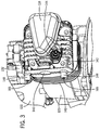
FIG. 3 is a perspective view of a cylinder block and a cylinder head according to an exemplary embodiment. -
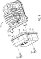
FIG. 4 is an exploded view of the cylinder head ofFIG. 3 and a muffler according to an exemplary embodiment. -
FIG. 5 is a perspective view of the muffler coupled to the cylinder head ofFIG. 4 with a muffler guard, according to an exemplary embodiment. -
FIG. 6 is a sectional view taken generally along line 6-6 ofFIG. 5 . -
FIG. 7A is a front view of a muffler according to an exemplary embodiment. -
FIG. 7B is a sectional view taken generally alongline 7B-7B ofFIG. 7A . -
FIG. 7C an enlarged view taken generally within theencircled region 7C ofFIG. 7B . -
FIG. 8A is a sectional view of a fitting according to an exemplary embodiment. -
FIG. 8B is a sectional view of a fitting according to another exemplary embodiment. - Before turning to the figures, which illustrate the exemplary embodiments in detail, it should be understood that the present application is not limited to the details or methodology set forth in the description or illustrated in the figures. It should also be understood that the terminology is for the purpose of description only and should not be regarded as limiting.
- Referring to
FIG. 1 , aninternal combustion engine 110 includes ablower housing 112 covering a top of theengine 110, with anair intake 114 and afuel tank 116 mounted to a side of theengine 110. Arecoil starter 126 is attached to the top of theblower housing 112. - The
engine 110 further includes acrankcase 120 and asump 122 fastened to the underside of thecrankcase 120. Thecrankcase 120 supports internal components of theengine 110, such as a piston, a connecting rod, a camshaft, and other components. Thesump 122 forms a base of thecrankcase 120, and holds a pool of oil lubricant within thecrankcase 120. Avertical crankshaft 124 extends from thecrankcase 120, through thesump 122, and may be used to drive power equipment, such as a rotary lawn mower, a pressure washer pump, a secondary generator, or other equipment. In other embodiments, the engine may include a horizontal crankshaft, an automatic starter, and thecrankcase 120 andsump 122 may be integrally cast. -
FIG. 2 shows a side view of theengine 110, with various engine components not shown to better display theengine 110 structure. For example, theblower housing 112 is omitted to show components on the top of theengine 110, including abase 130 of a blower scroll, anignition armature 132, and arocker cover 118. The base 130 guides air from a blower fan to cool parts of theengine 110 heated as a result of the combustion process. Theignition armature 132 produces a timed electric charge used by aspark plug 144 to ignite the fuel. - The
rocker cover 118 is mounted to a side of theengine 110, and encases rockers 138 (seeFIG. 5 ) that drive intake and exhaust valves. Beneath therocker cover 118 androckers 138 is acylinder head 142 covering acylinder block 140. Thecylinder head 142 caps thecylinder block 140, forming a combustion chamber. Intake and exhaust valves are controlled by the rockers, and control the flow of air in and exhaust out of the combustion chamber. - Also shown in
FIG. 2 , amuffler 128 is attached to a side of theengine 110. Themuffler 128 reduces noise emissions from combustion processes occurring within theengine 110. Themuffler 128 includes ahousing 136 having a generally rectangular body formed from two shells crimped together. In other embodiments, the body may be generally circular, square, octagonal, or other shapes. Thehousing 136 includes mountingapertures 156, with themuffler 128 fastened to thecylinder head 142 withfasteners 134 extending through the mountingapertures 156. In the center of themuffler 128 are a series ofperforations 160 on thehousing 136. Exhaust gases exit themuffler 128 through theperforations 160. - While
FIG. 2 shows themuffler 128 according to an exemplary embodiment, other types and forms of mufflers may also use the teachings disclosed herein. For example, in other embodiments themuffler 128 is attached to a cylinder block instead of a cylinder head. In some embodiments, themuffler 128 may be coupled to theengine 110 with other types of fasteners, such as self-tapping screws, hooks, pins, bars, welds, etc., and combinations thereof. Also, in some embodiments, themuffler 128 is attached with different numbers of fasteners. For example, in at least one embodiment, a muffler includes a loop to be engaged by a hook extending from a cylinder block. In some embodiments, theperforations 160 of the outlet are not in the center of the muffler housing. In other embodiments, the muffler outlet includes a tube through which exhaust gases exit. Muffler geometries and dimensions vary depending upon the particular frequency and amplitude of sound to be dissipated and other factors, such as an intended application. - In an exemplary embodiment, the
engine 110 is a four-stroke engine. An exhaust conduit 150 (seeFIG. 6 ) extends within thecylinder head 142. In other embodiments the exhaust conduit extends within thecylinder block 140. The exhaust gases exit thecylinder head 142 through theexhaust port 146, and into themuffler 128. -
FIG. 3 shows thecylinder head 142, anexhaust port 146, and structure to attach themuffler 128 to the exhaust port 146 (with various engine components not shown to better display the structure). Theexhaust port 146 is shown as a round aperture on a side of thecylinder head 142. Exhaust gases are directed from the combustion chamber, past theexhaust valve 164, and to theexhaust port 146. WhileFIG. 3 shows theexhaust port 146 as an aperture, in other embodiments the exhaust port is a tube or conduit extending from the engine. - Two
bosses 148 extend from thecylinder head 142. Thebosses 148 are positioned to the sides of theexhaust port 146, and include tappedapertures 166 to receive thefasteners 134. In an exemplary embodiment, thebosses 148 are positioned such that the centers of thebosses 148 are more than one inch from the center of the exhaust port 146 (e.g., about two inches). Placement of thebosses 148 away from theexhaust port 146 reduces heat transfer from exhaust gases exiting through theexhaust port 146. For example, sufficient distance between thebosses 148 and theexhaust port 146 allows for general purpose, self-tapping screws to be used as opposed to specialty bolts designed to handle high temperatures without much thermal expansion. With embodiments employing self-tapping screws, theapertures 166 are cored, not tapped. -
FIG. 4 shows an exploded view of thecylinder head 142 and themuffler 128, with fasteners 134 (e.g., screws, bolts, etc.) for attaching themuffler 128 to thecylinder head 142. When themuffler 128 is attached to thecylinder head 142, exhaust gases are directed out of theexhaust port 146 and into anintake pipe 168 of themuffler 128. As shown inFIGS. 2 and4 , thefasteners 134 pass through theapertures 156 in aflat portion 152 along anedge 154 of themuffler housing 136. Use of theflat portion 152 along theedge 154 reduces the surface area of the interface between thefasteners 134 and themuffler 128, further reducing heat transfer to thefasteners 134. -
FIG. 5 shows a perspective view of themuffler 128 fastened to thecylinder head 142 via thefasteners 134 ofFIG. 4 . Also shown inFIG. 5 , a muffler guard, in the form of acage 162, surrounds themuffler 128. In some exemplary embodiments, thecage 162 is made of metal bars (e.g., steel, iron, aluminum, etc.) welded together in a matrix. Thecage 162 is spaced apart from thehousing 136 of themuffler 128 to reduce heat transfer to thecage 162, and to limit access to themuffler 128. Thecage 162 also helps prevent foreign objects, such as dry leaves or an operator, from contacting thehousing 136, which may get quite hot. In other embodiments, the muffler guard is a second perforated housing, formed from a high-temperature plastic or composite shell. Still other embodiments employ other forms of commercially available muffler guards. - According to an exemplary embodiment, the
cage 162 is attached to theengine 110 via thefasteners 134. For example, thefasteners 134 pass through mountingloops 170 of thecage 162. Thefasteners 134 then pass through the mountingapertures 156 of themuffler 128, and into thebosses 148. In other embodiments, the fasteners first pass through the mountingapertures 156 of the muffler, then through the mountingloops 170 of thecage 162, and then into thebosses 148. Placing thebosses 148 away from the exhaust port helps to reduce heat transfer to thecage 162. Accordingly, thefasteners 134 that attach themuffler 128 may simultaneously be used to attach thecage 162. In other embodiments, different types or numbers of fasteners are used to attach thecage 162. - Referring to
FIG. 6 , theexhaust conduit 150 is shown extending within thecylinder head 142 to theintake pipe 168 of themuffler 128. Theexhaust conduit 150 is chamfered proximate to where theexhaust conduit 150 contacts theintake pipe 168 of themuffler 128. Exhaust gases entering themuffler 128 enter afirst resonance chamber 172. One side of thechamber 172 is formed from a separator 174 (or baffle) within themuffler 128. The separator includes a dome-like structure 176. The other sides of thechamber 172 are formed from thehousing 136. Exhaust gases pass from thefirst chamber 172 through a series of perforations in theseparator 174, into asecond chamber 178. As shown inFIGS. 2 and6 , exhaust gases exit thesecond chamber 178 through theperforations 160 on thehousing 136. Engine noise is dissipated in thefirst chamber 172, and further dissipated in thesecond chamber 178. Other embodiments include mufflers with different numbers of chambers and separators. In some embodiments employing tube outlets, a spark arrester may be coupled to the end of the tube. - Still referring to the exemplary embodiment shown in
FIG. 6 , theintake pipe 168 of the muffler is tapered. The cross-sectional area of theintake pipe 168 decreases with distance away from themuffler 128. In some embodiments, the rate of decrease is linear, while in other embodiments, the rate of decrease is non-linear and not continuous. During attachment of themuffler 128 to theengine 110, theintake pipe 168 is inserted into theexhaust port 146, such that the end of theintake pipe 168 contacts chamfered walls of theexhaust conduit 150. - When the
engine 110 is running, heat transfers from hot exhaust gases passing through theexhaust conduit 150 and into engine components, such as theintake pipe 168 of themuffler 128. The engine components expand, with different materials expanding at different rates and to different extents. In a preferred embodiment, theintake pipe 168 is designed so that thermal expansion of the materials will improve the seal between theintake pipe 168 and theexhaust conduit 150. -
FIGS. 7A ,7B, and 7C show amuffler 210 according to another exemplary embodiment. Themuffler 210 is formed from afront shell 212 and aback shell 214 crimped together around edges 216. Thefront shell 212 includes anintake pipe 218 extending outward from thefront shell 212. - A
flexible portion 220 of thefront shell 212 surrounds theintake pipe 218 and has an outwardly extending curvature. When theintake pipe 218 is inserted through anexhaust port 222 and into anexhaust conduit 224, resistance from contact at aninterface 226 between theintake pipe 218 and theexhaust conduit 224 generates a compressive force that is transferred through theintake pipe 218 to theflexible portion 220 of thefront shell 212. Theflexible portion 220 deflects, storing the force like a spring.Fasteners 236 hold theflexible portion 220 of thefront shell 212 in the deflected position, and the force holds the end of theintake pipe 218 tightly against theexhaust conduit 224 under pressure such that an airtight seal is formed. In other embodiments, theintake pipe 218 itself is flexible, and stores compression force when pressed into theexhaust port 222. - The
exhaust conduit 224 shown inFIGS. 7B and 7C includes abevel 228 proximate to theexhaust port 222. Thebevel 228 is angled outward to facilitate positioning of theintake pipe 218 into theexhaust port 222 during assembly. Additionally, theintake pipe 218 is coupled to theshell 214 with arounded fillet 230. Thefillet 230 reduces stress concentrations between theshell 214 and theintake pipe 218. When coupled, thefillet 230 fits the space provided by thebevel 228. - Further referring to
FIG. 7B , theexhaust conduit 224 further includes a backstop. The backstop is in the form of anannular step 232 or a shoulder at an end of a chamfered portion 234 of theexhaust conduit 224. When theintake pipe 218 is inserted into theexhaust conduit 224, thestep 232 blocks theintake pipe 218 from deeper insertion. Also, thestep 232 may increase the surface area ofcontact 226 between theintake pipe 218 and theexhaust conduit 224, providing a stronger seal. Further, thestep 232 guides exhaust gases into theintake pipe 218, away from leaking between theintake pipe 218 and theexhaust conduit 224. In other embodiments, the backstop is in the form of protrusions, hooks, crossing bars, or other structures that limit the ability of theintake pipe 218 to be further inserted into theexhaust conduit 224. - Referring to
FIG. 7C , in an exemplary embodiment, the angle of taper θ' of theintake pipe 218 is less than a chamfer angle θ" of theexhaust conduit 224. In some embodiments, the difference of relative angles θ', θ" is approximately between two to twenty degrees, preferably between five to ten degrees, such as about seven degrees. A meeting of two angled surfaces is intended to increase the surface area of thecontact 226, producing a better seal. -
FIG. 8A shows afitting arrangement 310, with anintake 312 of a muffler and anexhaust port 314 of an engine. Theintake 312 includes anintake pipe 318 having a uniform cross-section. Theexhaust port 314 is formed at the end of anexhaust conduit 320. Theexhaust conduit 320 has a chamferedportion 322 with a widening cross-sectional area leading to theexhaust port 314. Theintake pipe 318 may be inserted into the chamferedportion 322, where an end of theintake pipe 318 contacts walls of theexhaust conduit 320. As theintake pipe 318 is inserted, some of the insertion force compresses an interface between theintake pipe 318 and the chamferedportion 322, producing an airtight seal. -
FIG. 8B shows afitting arrangement 510, with anintake 512 of a muffler and anexhaust port 514 of an engine. Theintake 512 includes anintake pipe 516 having arounded end 518 with a cross-sectional area narrowing away from the muffler. In some embodiments, the rate of narrowing is not constant. Theexhaust port 514 is formed at the end of anexhaust conduit 520. Theexhaust conduit 520 has a cross-sectional area that widens away from the engine. In some embodiments, the rate of widening is not constant. Theexhaust conduit 520 further includes astep 522 that serves has a backstop to limit a distance of insertion of theintake pipe 516 into theexhaust conduit 520. - The construction and arrangements of the muffler attachment, as shown in the various exemplary embodiments are illustrative only. Although only a few embodiments have been described in detail in this disclosure, many modifications are possible (e.g., variations in sizes, dimensions, structures, shapes and proportions of the various elements, values of parameters, mounting arrangements, use of materials, colors, orientations, etc.) without materially departing from the novel teachings and advantages of the subject matter described herein. For example, elements shown as integrally formed may be constructed of multiple parts or elements, the position of elements may be reversed or otherwise varied, and the nature or number of discrete elements or positions may be altered or varied. In some embodiments, fitting attachments taught herein may be applied to fittings between components in power equipment that do not include a muffler. The order or sequence of any process, logical algorithm, or method steps may be varied or re-sequenced according to alternative embodiments. Other substitutions, modifications, changes and omissions may also be made in the design, operating conditions and arrangement of the various exemplary embodiments without departing from the scope of the present invention as defined by the appended claims.
Claims (14)
- An engine (110), comprising:an exhaust conduit (150) comprising an exhaust port (146) on an end thereof, wherein the exhaust conduit has an angled inside surface having a cross section widening toward the exhaust port; anda muffler (128) comprising a housing (136) with an intake pipe (168), wherein the intake pipe is inserted through the exhaust port such that the intake pipe is wedged into the angled inside surface of the exhaust conduit.
- The engine (110) of claim 1, further comprising a fastener (134) and a boss (148), the fastener extending through a mounting aperture (156) in the housing of the muffler, and into the boss, whereby the muffler is fastened to the engine.
- The engine (110) of claim 2, wherein the boss (148) is a distance greater than one inch from the exhaust port.
- The engine (110) of claim 2 or claim 3, further comprising a muffler guard (162), the muffler guard fastened to the boss with the fastener.
- The engine (110) of any of claims 2 to 4, wherein the mounting aperture (156) in the housing extends from a side thereof, and the fastener (134) does not pass directly through a chamber of the muffler.
- The engine (110) of any preceding claim, wherein the intake pipe (168) of the muffler tapers having a cross section narrowing away from the muffler.
- The engine (110) of any preceding claim, wherein the exhaust conduit (150) includes a backstop that limits an insertion distance of the intake pipe (168) into the exhaust port (146).
- The engine (110) of any preceding claim, wherein the muffler comprises a flexible portion (220) of the housing, wherein, upon attachment to the engine, compression force is stored via elastic deflection of the flexible portion.
- The engine (110) of claim 8, wherein the flexible portion (220) of the housing (136) can flex in response to a compression of the intake pipe when inserted into the exhaust port, forming an airtight seal over the exhaust port.
- The engine (110) of any claims 7 to 9, wherein in the backstop is an annular step extending around the inside surface of the exhaust port, and wherein the exhaust conduit further includes a bevel adjacent to the exhaust port.
- The engine (110) of claim 10, wherein the intake pipe (168) has a first angle of tapering and the angled surface of the exhaust port (146), between the annular step and the bevel, has a second angle of tapering, wherein the second angle of tapering is greater than the first angle of tapering.
- The engine (110) of any preceding claim, wherein the housing (136) further comprises an outlet.
- The engine (110) of any preceding claim, wherein the intake pipe (168) is integral with the housing.
- The engine (110) of any of claims 2 to 13, wherein the fastener is a threaded fastener (134) that extends through the mounting aperture (156) through a mounting loop (170) in the muffler guard, and into the boss (148), wherein the boss extends from a cylinder block of the engine.
Applications Claiming Priority (2)
| Application Number | Priority Date | Filing Date | Title |
|---|---|---|---|
| US12/508,424 US8251173B2 (en) | 2009-07-23 | 2009-07-23 | Muffler attachment system |
| PCT/US2010/042133 WO2011011260A1 (en) | 2009-07-23 | 2010-07-15 | Muffler attachment system |
Publications (2)
| Publication Number | Publication Date |
|---|---|
| EP2456964A1 EP2456964A1 (en) | 2012-05-30 |
| EP2456964B1 true EP2456964B1 (en) | 2016-08-17 |
Family
ID=42646362
Family Applications (1)
| Application Number | Title | Priority Date | Filing Date |
|---|---|---|---|
| EP10737163.5A Active EP2456964B1 (en) | 2009-07-23 | 2010-07-15 | Muffler attachment system |
Country Status (5)
| Country | Link |
|---|---|
| US (2) | US8251173B2 (en) |
| EP (1) | EP2456964B1 (en) |
| CN (2) | CN103953428B (en) |
| AU (1) | AU2010274133B2 (en) |
| WO (1) | WO2011011260A1 (en) |
Families Citing this family (16)
| Publication number | Priority date | Publication date | Assignee | Title |
|---|---|---|---|---|
| DE102010019959A1 (en) * | 2010-05-08 | 2011-11-10 | J. Eberspächer GmbH & Co. KG | silencer |
| JP5624850B2 (en) * | 2010-10-29 | 2014-11-12 | 株式会社マキタ | engine |
| DE202011000529U1 (en) * | 2011-03-09 | 2012-06-12 | Makita Corporation | Arrangement of a silencer on an internal combustion engine with improved coupling to the cylinder |
| USD694689S1 (en) * | 2012-04-13 | 2013-12-03 | General Electric Company | Muffler |
| USD720670S1 (en) | 2013-09-05 | 2015-01-06 | General Electric Company | Muffler |
| USD745840S1 (en) * | 2014-06-09 | 2015-12-22 | General Electric Company | Muffler |
| US20190032531A1 (en) * | 2016-01-30 | 2019-01-31 | Koki Holdings Co., Ltd. | Engine and engine work machine |
| JP2017198112A (en) * | 2016-04-26 | 2017-11-02 | 株式会社マキタ | Engine muffler |
| CN114135365A (en) * | 2021-12-31 | 2022-03-04 | 长沙灵动航空科技有限公司 | Silencing device for power generation system |
| USD1085012S1 (en) | 2023-10-11 | 2025-07-22 | Northern Tool & Equipment Company, Inc. | Generator assembly |
| USD1085006S1 (en) | 2023-10-11 | 2025-07-22 | Northern Tool & Equipment Company, Inc. | Generator assembly |
| USD1085009S1 (en) | 2023-10-11 | 2025-07-22 | Northern Tool & Equipment Company, Inc. | Generator assembly |
| USD1085008S1 (en) | 2023-10-11 | 2025-07-22 | Northern Tool & Equipment Company, Inc. | Generator assembly |
| USD1085010S1 (en) | 2023-10-11 | 2025-07-22 | Northern Tool & Equipment Company, Inc. | Generator assembly |
| USD1085011S1 (en) | 2023-10-11 | 2025-07-22 | Northern Tool & Equipment Company, Inc. | Generator assembly |
| USD1085007S1 (en) | 2023-10-11 | 2025-07-22 | Northern Tool & Equipment Company, Inc. | Generator assembly |
Family Cites Families (46)
| Publication number | Priority date | Publication date | Assignee | Title |
|---|---|---|---|---|
| US3106985A (en) * | 1960-12-05 | 1963-10-15 | Kenneth J Recupito | Muffler apparatus |
| US3378099A (en) * | 1967-09-15 | 1968-04-16 | Briggs & Stratton Corp | Muffler and outlet tube for small internal combustion engines |
| AU446195B2 (en) | 1970-05-12 | 1974-02-27 | Victa Limited | Improvements in mufflers for internal combustion engines |
| US3863734A (en) | 1972-10-25 | 1975-02-04 | Tecumseh Products Co | Muffler for internal combustion engines |
| US3945354A (en) | 1973-08-09 | 1976-03-23 | Textron Inc. | Exhaust port of two cycle engine |
| BR7503284A (en) | 1974-05-28 | 1976-04-27 | Hinderks M V | IMPROVED DEVICES FOR TREATMENT OF GASES FROM INTERNAL COMBUSTION ENGINES AND VEHICLES AND ENGINES THAT USE THESE DEVICES AND FILMING MATERIAL FOR THE SAME |
| US4182121A (en) * | 1976-10-26 | 1980-01-08 | Chrysler Corporation | Exhaust tuning for transverse automobile engine |
| AU517657B2 (en) | 1976-10-26 | 1981-08-20 | Chrysler Corporation | Articulated exhaust system |
| US4209177A (en) * | 1979-01-15 | 1980-06-24 | Chrysler Corporation | Exhaust seal ring |
| US4286675A (en) | 1979-06-25 | 1981-09-01 | Beaird-Poulan Division Of Emerson Electric Co. | Narrow profile power handle for line trimmer and the like |
| US4252092A (en) | 1979-09-04 | 1981-02-24 | Tecumseh Products Company | Compression release mechanism |
| US4306522A (en) | 1980-06-19 | 1981-12-22 | Briggs & Stratton Corporation | Transfer port duct for two-stroke engines |
| JPS6012885Y2 (en) | 1980-12-25 | 1985-04-25 | 株式会社共立 | Exhaust muffler for multiple cylinder engines |
| USRE33050E (en) | 1985-12-03 | 1989-09-12 | White Consolidated Industries, Inc. | Hand held gas engine blower |
| US4682571A (en) | 1985-12-17 | 1987-07-28 | Tecumseh Products Company | Exhaust gas recirculation system for crankcase scavenged two cycle engine |
| DE3729477C3 (en) * | 1987-09-03 | 1999-09-09 | Stihl Maschf Andreas | Exhaust silencer for two-stroke engines, especially for portable tools such as chainsaws |
| JPH01262321A (en) | 1988-04-13 | 1989-10-19 | Suzuki Motor Co Ltd | Exhaust diffuser of two-cycle engine |
| DE3916872C1 (en) * | 1989-05-24 | 1990-11-15 | Friedrich Boysen Gmbh & Co Kg, 7272 Altensteig, De | |
| US5139107A (en) * | 1990-12-11 | 1992-08-18 | Kioritz Corporation | Exhaust muffler for internal combustion engines |
| US5211013A (en) * | 1991-09-17 | 1993-05-18 | Tecumseh Products Company | Muffler heat shield and method of attachment |
| JPH07310554A (en) | 1993-03-31 | 1995-11-28 | Mitsubishi Heavy Ind Ltd | Crank case compression type two-cycle engine |
| JPH06317150A (en) | 1993-05-07 | 1994-11-15 | Kubota Corp | Muffler cooling device for engine reverse type forced air cooling device |
| US5383427A (en) | 1993-07-19 | 1995-01-24 | Wci Outdoor Products, Inc. | Two-cycle, air-cooled uniflow gasoline engine for powering a portable tool |
| US5521339A (en) * | 1994-11-18 | 1996-05-28 | Wci Outdoor Products, Inc. | Catalyst muffler system |
| JP3280209B2 (en) * | 1995-10-20 | 2002-04-30 | 株式会社共立 | Muffler structure of internal combustion engine |
| ID27315A (en) | 1998-05-04 | 2001-03-22 | Cuyuna Engine Company Inc | MULTI-FUEL MACHINERY |
| US6298811B1 (en) | 1998-09-29 | 2001-10-09 | Komatsu Zenoah Co. | Stratified scavenging two-cycle engine |
| SE513446C2 (en) | 1999-01-19 | 2000-09-11 | Electrolux Ab | Crankcase coil internal combustion engine of two stroke type |
| JP3077693B1 (en) * | 1999-04-12 | 2000-08-14 | 国産部品工業株式会社 | Pipe fittings |
| US6832664B2 (en) * | 2000-05-19 | 2004-12-21 | Siemens Vdo Automotive Inc. | Clampless hose retainer mechanism |
| KR100507168B1 (en) * | 2002-10-31 | 2005-08-11 | 현대자동차주식회사 | Appararus to fix Muffler of Vehicle |
| US7195094B2 (en) | 2003-02-03 | 2007-03-27 | Briggs & Stratton Corporation | Vibration reduction apparatus |
| DE10304326A1 (en) * | 2003-02-04 | 2004-08-12 | Andreas Stihl Ag & Co. Kg | muffler assembly |
| US6975216B2 (en) | 2003-06-04 | 2005-12-13 | Briggs & Stratton Corporation | System and method for indicating fluid condition |
| US6952056B2 (en) | 2003-08-06 | 2005-10-04 | Briggs & Stratton Power Products Group, Llc | Generator including vertically shafted engine |
| JP4367918B2 (en) * | 2004-01-09 | 2009-11-18 | 本田技研工業株式会社 | Small engine exhaust system |
| US7134418B2 (en) | 2004-06-21 | 2006-11-14 | Briggs & Stratton Corporation | Four-stroke internal combustion engine |
| US7146806B2 (en) | 2004-07-07 | 2006-12-12 | Homelite Technologies, Ltd. | Internal combustion engine cylinder and muffler assembly with catalytic converter |
| JP3955291B2 (en) | 2004-07-13 | 2007-08-08 | 株式会社共立 | Muffler with catalyst for internal combustion engine |
| JP3955293B2 (en) * | 2004-08-06 | 2007-08-08 | 株式会社共立 | Muffler with catalyst for internal combustion engine |
| US7314397B2 (en) | 2005-05-13 | 2008-01-01 | Briggs & Stratton Corporation | Standby generator |
| JP4489645B2 (en) * | 2005-06-23 | 2010-06-23 | 本田技研工業株式会社 | General-purpose engine muffler |
| MY148994A (en) * | 2005-06-23 | 2013-06-28 | Honda Motor Co Ltd | Muffler unit for general-purpose engine |
| JP4814657B2 (en) | 2006-03-07 | 2011-11-16 | ハスクバーナ・ゼノア株式会社 | 2-cycle engine |
| DE102006037201A1 (en) * | 2006-08-09 | 2008-02-14 | Andreas Stihl Ag & Co. Kg | Hand-held implement |
| US7492050B2 (en) | 2006-10-24 | 2009-02-17 | Briggs & Stratton Corporation | Cooling system for a portable generator |
-
2009
- 2009-07-23 US US12/508,424 patent/US8251173B2/en active Active
-
2010
- 2010-07-15 CN CN201410143965.6A patent/CN103953428B/en not_active Expired - Fee Related
- 2010-07-15 CN CN201080031644.7A patent/CN102472145B/en not_active Expired - Fee Related
- 2010-07-15 EP EP10737163.5A patent/EP2456964B1/en active Active
- 2010-07-15 WO PCT/US2010/042133 patent/WO2011011260A1/en not_active Ceased
- 2010-07-15 AU AU2010274133A patent/AU2010274133B2/en not_active Ceased
-
2012
- 2012-07-16 US US13/550,038 patent/US8413760B2/en active Active
Also Published As
| Publication number | Publication date |
|---|---|
| CN103953428B (en) | 2017-12-26 |
| US20110017336A1 (en) | 2011-01-27 |
| CN102472145A (en) | 2012-05-23 |
| US20120279199A1 (en) | 2012-11-08 |
| EP2456964A1 (en) | 2012-05-30 |
| CN102472145B (en) | 2014-05-14 |
| CN103953428A (en) | 2014-07-30 |
| AU2010274133A1 (en) | 2012-02-02 |
| US8413760B2 (en) | 2013-04-09 |
| AU2010274133B2 (en) | 2016-07-07 |
| US8251173B2 (en) | 2012-08-28 |
| WO2011011260A1 (en) | 2011-01-27 |
Similar Documents
| Publication | Publication Date | Title |
|---|---|---|
| US8251173B2 (en) | Muffler attachment system | |
| JP5581196B2 (en) | Engine cooling system | |
| EP2479390B1 (en) | Exhaust muffler for multipurpose engine | |
| US8424498B2 (en) | Engine blower scroll | |
| CA2080216C (en) | External spark arrestor | |
| CA2889282C (en) | An air flow guide for an internal combustion engine | |
| EP2456965B1 (en) | Rocker cover system | |
| US9605572B2 (en) | Muffler and engine system | |
| US7896127B2 (en) | Muffler unit for general-purpose engine | |
| JP4455423B2 (en) | General-purpose engine muffler structure | |
| JPWO2017130660A1 (en) | Engine and engine working machine | |
| JPH09158743A (en) | Exhaust pipe heat shield with turbocharger | |
| NZ215687A (en) | An exhaust manifold: baffle deflects incoming hot exhaust away from manifolds housing | |
| US7549413B1 (en) | Flame protection gasket | |
| WO2006019286A1 (en) | Front muffler | |
| JP4078035B2 (en) | Muffler for general-purpose engine | |
| JP2007002713A (en) | General-purpose engine muffler cover structure | |
| JP2005299564A (en) | Exhaust manifold gasket | |
| KR20130050836A (en) | Structure of muffler for vehicle |
Legal Events
| Date | Code | Title | Description |
|---|---|---|---|
| PUAI | Public reference made under article 153(3) epc to a published international application that has entered the european phase |
Free format text: ORIGINAL CODE: 0009012 |
|
| 17P | Request for examination filed |
Effective date: 20120207 |
|
| AK | Designated contracting states |
Kind code of ref document: A1 Designated state(s): AL AT BE BG CH CY CZ DE DK EE ES FI FR GB GR HR HU IE IS IT LI LT LU LV MC MK MT NL NO PL PT RO SE SI SK SM TR |
|
| DAX | Request for extension of the european patent (deleted) | ||
| 17Q | First examination report despatched |
Effective date: 20150205 |
|
| GRAP | Despatch of communication of intention to grant a patent |
Free format text: ORIGINAL CODE: EPIDOSNIGR1 |
|
| INTG | Intention to grant announced |
Effective date: 20160216 |
|
| GRAS | Grant fee paid |
Free format text: ORIGINAL CODE: EPIDOSNIGR3 |
|
| GRAA | (expected) grant |
Free format text: ORIGINAL CODE: 0009210 |
|
| AK | Designated contracting states |
Kind code of ref document: B1 Designated state(s): AL AT BE BG CH CY CZ DE DK EE ES FI FR GB GR HR HU IE IS IT LI LT LU LV MC MK MT NL NO PL PT RO SE SI SK SM TR |
|
| REG | Reference to a national code |
Ref country code: GB Ref legal event code: FG4D |
|
| REG | Reference to a national code |
Ref country code: CH Ref legal event code: EP |
|
| REG | Reference to a national code |
Ref country code: IE Ref legal event code: FG4D |
|
| REG | Reference to a national code |
Ref country code: AT Ref legal event code: REF Ref document number: 821337 Country of ref document: AT Kind code of ref document: T Effective date: 20160915 |
|
| REG | Reference to a national code |
Ref country code: DE Ref legal event code: R096 Ref document number: 602010035610 Country of ref document: DE |
|
| REG | Reference to a national code |
Ref country code: NL Ref legal event code: MP Effective date: 20160817 |
|
| REG | Reference to a national code |
Ref country code: LT Ref legal event code: MG4D |
|
| REG | Reference to a national code |
Ref country code: AT Ref legal event code: MK05 Ref document number: 821337 Country of ref document: AT Kind code of ref document: T Effective date: 20160817 |
|
| PG25 | Lapsed in a contracting state [announced via postgrant information from national office to epo] |
Ref country code: HR Free format text: LAPSE BECAUSE OF FAILURE TO SUBMIT A TRANSLATION OF THE DESCRIPTION OR TO PAY THE FEE WITHIN THE PRESCRIBED TIME-LIMIT Effective date: 20160817 Ref country code: NL Free format text: LAPSE BECAUSE OF FAILURE TO SUBMIT A TRANSLATION OF THE DESCRIPTION OR TO PAY THE FEE WITHIN THE PRESCRIBED TIME-LIMIT Effective date: 20160817 Ref country code: NO Free format text: LAPSE BECAUSE OF FAILURE TO SUBMIT A TRANSLATION OF THE DESCRIPTION OR TO PAY THE FEE WITHIN THE PRESCRIBED TIME-LIMIT Effective date: 20161117 Ref country code: FI Free format text: LAPSE BECAUSE OF FAILURE TO SUBMIT A TRANSLATION OF THE DESCRIPTION OR TO PAY THE FEE WITHIN THE PRESCRIBED TIME-LIMIT Effective date: 20160817 Ref country code: LT Free format text: LAPSE BECAUSE OF FAILURE TO SUBMIT A TRANSLATION OF THE DESCRIPTION OR TO PAY THE FEE WITHIN THE PRESCRIBED TIME-LIMIT Effective date: 20160817 |
|
| PG25 | Lapsed in a contracting state [announced via postgrant information from national office to epo] |
Ref country code: ES Free format text: LAPSE BECAUSE OF FAILURE TO SUBMIT A TRANSLATION OF THE DESCRIPTION OR TO PAY THE FEE WITHIN THE PRESCRIBED TIME-LIMIT Effective date: 20160817 Ref country code: AT Free format text: LAPSE BECAUSE OF FAILURE TO SUBMIT A TRANSLATION OF THE DESCRIPTION OR TO PAY THE FEE WITHIN THE PRESCRIBED TIME-LIMIT Effective date: 20160817 Ref country code: PL Free format text: LAPSE BECAUSE OF FAILURE TO SUBMIT A TRANSLATION OF THE DESCRIPTION OR TO PAY THE FEE WITHIN THE PRESCRIBED TIME-LIMIT Effective date: 20160817 Ref country code: LV Free format text: LAPSE BECAUSE OF FAILURE TO SUBMIT A TRANSLATION OF THE DESCRIPTION OR TO PAY THE FEE WITHIN THE PRESCRIBED TIME-LIMIT Effective date: 20160817 Ref country code: GR Free format text: LAPSE BECAUSE OF FAILURE TO SUBMIT A TRANSLATION OF THE DESCRIPTION OR TO PAY THE FEE WITHIN THE PRESCRIBED TIME-LIMIT Effective date: 20161118 Ref country code: SE Free format text: LAPSE BECAUSE OF FAILURE TO SUBMIT A TRANSLATION OF THE DESCRIPTION OR TO PAY THE FEE WITHIN THE PRESCRIBED TIME-LIMIT Effective date: 20160817 Ref country code: PT Free format text: LAPSE BECAUSE OF FAILURE TO SUBMIT A TRANSLATION OF THE DESCRIPTION OR TO PAY THE FEE WITHIN THE PRESCRIBED TIME-LIMIT Effective date: 20161219 |
|
| PG25 | Lapsed in a contracting state [announced via postgrant information from national office to epo] |
Ref country code: EE Free format text: LAPSE BECAUSE OF FAILURE TO SUBMIT A TRANSLATION OF THE DESCRIPTION OR TO PAY THE FEE WITHIN THE PRESCRIBED TIME-LIMIT Effective date: 20160817 Ref country code: RO Free format text: LAPSE BECAUSE OF FAILURE TO SUBMIT A TRANSLATION OF THE DESCRIPTION OR TO PAY THE FEE WITHIN THE PRESCRIBED TIME-LIMIT Effective date: 20160817 |
|
| REG | Reference to a national code |
Ref country code: DE Ref legal event code: R097 Ref document number: 602010035610 Country of ref document: DE |
|
| PG25 | Lapsed in a contracting state [announced via postgrant information from national office to epo] |
Ref country code: SK Free format text: LAPSE BECAUSE OF FAILURE TO SUBMIT A TRANSLATION OF THE DESCRIPTION OR TO PAY THE FEE WITHIN THE PRESCRIBED TIME-LIMIT Effective date: 20160817 Ref country code: DK Free format text: LAPSE BECAUSE OF FAILURE TO SUBMIT A TRANSLATION OF THE DESCRIPTION OR TO PAY THE FEE WITHIN THE PRESCRIBED TIME-LIMIT Effective date: 20160817 Ref country code: SM Free format text: LAPSE BECAUSE OF FAILURE TO SUBMIT A TRANSLATION OF THE DESCRIPTION OR TO PAY THE FEE WITHIN THE PRESCRIBED TIME-LIMIT Effective date: 20160817 Ref country code: BG Free format text: LAPSE BECAUSE OF FAILURE TO SUBMIT A TRANSLATION OF THE DESCRIPTION OR TO PAY THE FEE WITHIN THE PRESCRIBED TIME-LIMIT Effective date: 20161117 Ref country code: BE Free format text: LAPSE BECAUSE OF FAILURE TO SUBMIT A TRANSLATION OF THE DESCRIPTION OR TO PAY THE FEE WITHIN THE PRESCRIBED TIME-LIMIT Effective date: 20160817 Ref country code: CZ Free format text: LAPSE BECAUSE OF FAILURE TO SUBMIT A TRANSLATION OF THE DESCRIPTION OR TO PAY THE FEE WITHIN THE PRESCRIBED TIME-LIMIT Effective date: 20160817 |
|
| REG | Reference to a national code |
Ref country code: FR Ref legal event code: PLFP Year of fee payment: 8 |
|
| PLBE | No opposition filed within time limit |
Free format text: ORIGINAL CODE: 0009261 |
|
| STAA | Information on the status of an ep patent application or granted ep patent |
Free format text: STATUS: NO OPPOSITION FILED WITHIN TIME LIMIT |
|
| 26N | No opposition filed |
Effective date: 20170518 |
|
| PG25 | Lapsed in a contracting state [announced via postgrant information from national office to epo] |
Ref country code: SI Free format text: LAPSE BECAUSE OF FAILURE TO SUBMIT A TRANSLATION OF THE DESCRIPTION OR TO PAY THE FEE WITHIN THE PRESCRIBED TIME-LIMIT Effective date: 20160817 |
|
| REG | Reference to a national code |
Ref country code: CH Ref legal event code: PL |
|
| REG | Reference to a national code |
Ref country code: IE Ref legal event code: MM4A |
|
| PG25 | Lapsed in a contracting state [announced via postgrant information from national office to epo] |
Ref country code: IE Free format text: LAPSE BECAUSE OF NON-PAYMENT OF DUE FEES Effective date: 20170715 Ref country code: LI Free format text: LAPSE BECAUSE OF NON-PAYMENT OF DUE FEES Effective date: 20170731 Ref country code: CH Free format text: LAPSE BECAUSE OF NON-PAYMENT OF DUE FEES Effective date: 20170731 |
|
| REG | Reference to a national code |
Ref country code: FR Ref legal event code: PLFP Year of fee payment: 9 |
|
| PG25 | Lapsed in a contracting state [announced via postgrant information from national office to epo] |
Ref country code: LU Free format text: LAPSE BECAUSE OF NON-PAYMENT OF DUE FEES Effective date: 20170715 |
|
| PG25 | Lapsed in a contracting state [announced via postgrant information from national office to epo] |
Ref country code: MT Free format text: LAPSE BECAUSE OF NON-PAYMENT OF DUE FEES Effective date: 20170715 |
|
| PG25 | Lapsed in a contracting state [announced via postgrant information from national office to epo] |
Ref country code: AL Free format text: LAPSE BECAUSE OF FAILURE TO SUBMIT A TRANSLATION OF THE DESCRIPTION OR TO PAY THE FEE WITHIN THE PRESCRIBED TIME-LIMIT Effective date: 20160817 |
|
| PGFP | Annual fee paid to national office [announced via postgrant information from national office to epo] |
Ref country code: IT Payment date: 20180713 Year of fee payment: 9 |
|
| PGFP | Annual fee paid to national office [announced via postgrant information from national office to epo] |
Ref country code: GB Payment date: 20180711 Year of fee payment: 9 |
|
| PG25 | Lapsed in a contracting state [announced via postgrant information from national office to epo] |
Ref country code: MC Free format text: LAPSE BECAUSE OF FAILURE TO SUBMIT A TRANSLATION OF THE DESCRIPTION OR TO PAY THE FEE WITHIN THE PRESCRIBED TIME-LIMIT Effective date: 20160817 Ref country code: HU Free format text: LAPSE BECAUSE OF FAILURE TO SUBMIT A TRANSLATION OF THE DESCRIPTION OR TO PAY THE FEE WITHIN THE PRESCRIBED TIME-LIMIT; INVALID AB INITIO Effective date: 20100715 |
|
| PG25 | Lapsed in a contracting state [announced via postgrant information from national office to epo] |
Ref country code: CY Free format text: LAPSE BECAUSE OF NON-PAYMENT OF DUE FEES Effective date: 20160817 |
|
| PG25 | Lapsed in a contracting state [announced via postgrant information from national office to epo] |
Ref country code: MK Free format text: LAPSE BECAUSE OF FAILURE TO SUBMIT A TRANSLATION OF THE DESCRIPTION OR TO PAY THE FEE WITHIN THE PRESCRIBED TIME-LIMIT Effective date: 20160817 |
|
| GBPC | Gb: european patent ceased through non-payment of renewal fee |
Effective date: 20190715 |
|
| PG25 | Lapsed in a contracting state [announced via postgrant information from national office to epo] |
Ref country code: TR Free format text: LAPSE BECAUSE OF FAILURE TO SUBMIT A TRANSLATION OF THE DESCRIPTION OR TO PAY THE FEE WITHIN THE PRESCRIBED TIME-LIMIT Effective date: 20160817 |
|
| PG25 | Lapsed in a contracting state [announced via postgrant information from national office to epo] |
Ref country code: GB Free format text: LAPSE BECAUSE OF NON-PAYMENT OF DUE FEES Effective date: 20190715 |
|
| PG25 | Lapsed in a contracting state [announced via postgrant information from national office to epo] |
Ref country code: IS Free format text: LAPSE BECAUSE OF FAILURE TO SUBMIT A TRANSLATION OF THE DESCRIPTION OR TO PAY THE FEE WITHIN THE PRESCRIBED TIME-LIMIT Effective date: 20161217 |
|
| PG25 | Lapsed in a contracting state [announced via postgrant information from national office to epo] |
Ref country code: IT Free format text: LAPSE BECAUSE OF NON-PAYMENT OF DUE FEES Effective date: 20190715 |
|
| REG | Reference to a national code |
Ref country code: DE Ref legal event code: R081 Ref document number: 602010035610 Country of ref document: DE Owner name: BRIGGS & STRATTON, LLC, WAUWATOSA, US Free format text: FORMER OWNER: BRIGGS & STRATTON CORP., WAUWATOSA, WIS., US |
|
| P01 | Opt-out of the competence of the unified patent court (upc) registered |
Effective date: 20230703 |
|
| PGFP | Annual fee paid to national office [announced via postgrant information from national office to epo] |
Ref country code: DE Payment date: 20250728 Year of fee payment: 16 |
|
| PGFP | Annual fee paid to national office [announced via postgrant information from national office to epo] |
Ref country code: FR Payment date: 20250725 Year of fee payment: 16 |