EP2456693B1 - Roller-belt sorter with control grid - Google Patents
Roller-belt sorter with control grid Download PDFInfo
- Publication number
- EP2456693B1 EP2456693B1 EP10730961.9A EP10730961A EP2456693B1 EP 2456693 B1 EP2456693 B1 EP 2456693B1 EP 10730961 A EP10730961 A EP 10730961A EP 2456693 B1 EP2456693 B1 EP 2456693B1
- Authority
- EP
- European Patent Office
- Prior art keywords
- belt
- conveyor
- rollers
- sorting
- articles
- Prior art date
- Legal status (The legal status is an assumption and is not a legal conclusion. Google has not performed a legal analysis and makes no representation as to the accuracy of the status listed.)
- Active
Links
- 238000000034 method Methods 0.000 claims description 4
- 238000003384 imaging method Methods 0.000 claims description 2
- 230000002452 interceptive effect Effects 0.000 claims description 2
- 230000008878 coupling Effects 0.000 description 2
- 238000010168 coupling process Methods 0.000 description 2
- 238000005859 coupling reaction Methods 0.000 description 2
- 239000011159 matrix material Substances 0.000 description 2
- 230000007246 mechanism Effects 0.000 description 2
- 230000002093 peripheral effect Effects 0.000 description 2
- 238000005096 rolling process Methods 0.000 description 2
- 125000006850 spacer group Chemical group 0.000 description 2
- 241000755266 Kathetostoma giganteum Species 0.000 description 1
- 230000001154 acute effect Effects 0.000 description 1
- 230000000903 blocking effect Effects 0.000 description 1
- 238000010586 diagram Methods 0.000 description 1
- 230000000717 retained effect Effects 0.000 description 1
- 238000000926 separation method Methods 0.000 description 1
Images


Classifications
-
- B—PERFORMING OPERATIONS; TRANSPORTING
- B65—CONVEYING; PACKING; STORING; HANDLING THIN OR FILAMENTARY MATERIAL
- B65G—TRANSPORT OR STORAGE DEVICES, e.g. CONVEYORS FOR LOADING OR TIPPING, SHOP CONVEYOR SYSTEMS OR PNEUMATIC TUBE CONVEYORS
- B65G17/00—Conveyors having an endless traction element, e.g. a chain, transmitting movement to a continuous or substantially-continuous load-carrying surface or to a series of individual load-carriers; Endless-chain conveyors in which the chains form the load-carrying surface
- B65G17/24—Conveyors having an endless traction element, e.g. a chain, transmitting movement to a continuous or substantially-continuous load-carrying surface or to a series of individual load-carriers; Endless-chain conveyors in which the chains form the load-carrying surface comprising a series of rollers which are moved, e.g. over a supporting surface, by the traction element to effect conveyance of loads or load-carriers
-
- B—PERFORMING OPERATIONS; TRANSPORTING
- B65—CONVEYING; PACKING; STORING; HANDLING THIN OR FILAMENTARY MATERIAL
- B65G—TRANSPORT OR STORAGE DEVICES, e.g. CONVEYORS FOR LOADING OR TIPPING, SHOP CONVEYOR SYSTEMS OR PNEUMATIC TUBE CONVEYORS
- B65G47/00—Article or material-handling devices associated with conveyors; Methods employing such devices
- B65G47/52—Devices for transferring articles or materials between conveyors i.e. discharging or feeding devices
- B65G47/68—Devices for transferring articles or materials between conveyors i.e. discharging or feeding devices adapted to receive articles arriving in one layer from one conveyor lane and to transfer them in individual layers to more than one conveyor lane or to one broader conveyor lane, or vice versa, e.g. combining the flows of articles conveyed by more than one conveyor
- B65G47/682—Devices for transferring articles or materials between conveyors i.e. discharging or feeding devices adapted to receive articles arriving in one layer from one conveyor lane and to transfer them in individual layers to more than one conveyor lane or to one broader conveyor lane, or vice versa, e.g. combining the flows of articles conveyed by more than one conveyor from a single conveyor lane consisting of one conveyor or several adjacent conveyors
Definitions
- the invention relates generally to power-driven conveyors and, more particularly, to a sorting system using a conveyor belt having article-supporting rollers that are selectively rotated in individual control cells arranged in a grid through which the belt passes.
- Shoe sorters, pusher bars, and diverting rails are used to sort packages and other articles on a conveyor.
- a conveyor used to unscramble packages before they are diverted takes up space.
- unscrambling packages of various sizes and orientation in a mass flow is difficult, especially at high throughput rates.
- WO 00/76887 A1 discloses a system according to the preamble of claim 1.
- the sorting conveyor includes a conveyor belt that advances in the direction of belt travel.
- the belt has article-supporting belt rollers that can rotate in a direction transverse to the direction of belt travel.
- the sorting conveyor also includes control elements arranged in a grid of multiple rows and columns of individually controlled grid cells. The control elements selectively rotate the belt rollers as they pass through the grid cells.
- a control system includes means for sensing the size and position of each article entering the belt.
- a trajectory along the conveyor belt is computed for each article based on its size and position on entering the belt by means for computing a trajectory.
- Each grid cell is selectively controlled according to the trajectories to divert articles transversely across the sorting conveyor along the trajectories.
- a method for sorting a flow of articles according to claim 9 comprises:
- Another version of the sorting conveyor includes a sorting conveyor that has rollers arranged in a grid of multiple rows and columns of individually controlled grid cells.
- a control system determines the size and position of each article entering the sorting conveyor, computes a trajectory for each article along the sorting conveyor from the article's size and position, and selectively controls the rollers in each grid cell according to the trajectories computed for the articles to actuate the rollers to divert articles across the sorting conveyor along the trajectories.
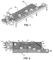
- FIGS. 1 and 2 A sorting system embodying features of the invention is shown in FIGS. 1 and 2 .
- An incoming mass flow of a variety of articles, such as boxes or packages P is sorted in a sorting conveyor 20 and transferred onto an abutting outbound singulating conveyor 22.
- the mass flow of packages, randomly oriented and positioned, is fed onto the sorting conveyor by an infeed conveyor 24 advancing in a conveying direction 26.
- the infeed conveyor may be realized as a powered roller conveyor, a flat belt, a modular conveyor belt, a chute, or the like.
- the sorting conveyor comprises a conveyor belt 28 having package-supporting rollers 30 ( FIG.
- the package-supporting belt rollers may be actively rotated in the direction of arrow 34 to divert packages toward the singulating conveyor 22.
- the transverse rollers in the sorting-conveyor belt 28 are selectively rotated in a grid 36 of individually actuated zones, or grid cells 38, arranged in rows R and columns C along the sorting conveyor's carryway.
- the rollers 30 in the sorting-conveyor belt 28 extend through the thickness of the belt so that they can be rotated by rolling contact with bearing surfaces underlying the belt as the belt advances in the direction of belt travel.
- One example of such a belt is the Intralox ® Series 7000 belt manufactured and sold by Intralox, L.L.C. of Harahan, Louisiana, U.S.A.
- FIG. 4 An exploded view of a portion of the bearing surfaces underlying the belt is shown in FIG. 4 .
- the belt rollers are supported atop an array of control elements-in this example, diverting rollers 40 positioned along the carryway.
- the peripheral surfaces of the diverting rollers serve as the bearing surfaces.
- the diverting rollers are mounted on a carryway pan 42, which is itself mounted in a conveyor frame (not shown).
- the pan is perforated with a plurality of circular openings 44 arranged in longitudinal columns 46 and lateral, or transverse, rows 47. The columns of openings are laterally aligned with the lateral positions of the belt rollers.
- Each opening rotatably receives a cartridge 48 supporting a freely rotatable diverting roller 40, which engages the belt rollers in the corresponding column as the belt advances in the direction of belt travel.
- the rolling contact between the belt rollers and the diverting rollers causes them both to roll on each other and rotate as long as their axes are oblique to each other.
- the diverting roller cartridge 48 includes a retainer ring 50 with diametrically opposite holes 52 supporting the ends of an axle received in a bore in the diverting roller 40.
- One of the holes can be a through hole through which the axle can be inserted into the cartridge and the diverting roller, and the other hole can have a blind end forming an end stop for the axle.
- the diverting roller is retained in the cartridge along a fixed axis with a salient portion of the roller protruding beyond the top of the retainer ring.
- Extending downward from the retainer ring encircling the diverting roller is an upper journal stem 54 having a cylindrical outer periphery indented inward from the ring to form a shoulder 56 between the peripheries of the ring and the stem.
- a lower journal stem 58 distal from the retainer ring has a smaller diameter than the upper journal stem.
- the periphery of the lower journal stem is indented inward of the periphery of the upper journal stem.
- a cartridge gear 60 is disposed between the upper stem and the lower stem.
- the cartridge gear is preferably a spur gear with peripheral teeth whose tips do not extend past the periphery of the upper journal stem.
- the cartridges 48 are received in the openings 44 in the carryway pan as shown in FIG. 4 .
- the walls of the openings form bearing surfaces 62 against which the upper journal stems can rotate. Because the diameter of the retainer rings exceeds the diameter of the openings, the ring's shoulder 56 rests atop the carryway pan with the smaller-diameter stems and gear portions suspended below.
- a plurality of gear plates 64 are movably positioned below the carryway pan. Each gear plate defines one of the individually actuatable grid cells. Actuated gears in the form of rack gears 66 are disposed on the gear plates. Each rack gear is positioned to engage the teeth of one of the cartridge gears to form a rack-and-pinion system that can rotate its cartridges in unison as the gear plate is translated.
- the gear plate has elongated openings 68 bounded on one side by a linear array of teeth 70 forming a rack gear. Each elongated opening 68 is positioned below one of the openings 44 in the carryway pan.
- the lower journal stem extends through the elongated openings in the gear plates, which are sandwiched between two other plates: the carryway pan 42 and a bottom plate 72.
- the bottom plate which is stationarily affixed to a portion of the conveyor frame, has a plurality of openings 74 vertically aligned with, but having a smaller diameter than, the openings in the carryway pan.
- the openings 74 are sized to rotatably receive the lower journal stems 58 of the cartridges. This helps align the upper and lower support plates to facilitate assembly of the roller drive mechanism and also confines the rotatable cartridges in rotation on fixed vertical axes.
- Confronting spacer pads 76 on the top of the bottom plate 72 and on the bottom of the top plate 42 maintain the proper spacing between the two plates and the movable gear plates 64.
- Spacers 78, fastened by bolts 80, washers 82, and nuts 84, maintain the spacing between the carryway pan and the bottom plate 72.
- Each gear plate 64 is translated by an individual linear actuator 86, such as an air cylinder, an electrical actuator, or a mechanical actuator.
- actuators in each grid cell column are attached at one end to a mounting bracket 88 mounted to the bottom of the bottom plate 72 by a coupling 90.
- the extension of an extension rod 92 from the other end of the actuator is connected by a coupling 94 to an actuator plate 96.
- Three internally threaded posts 98 extend upward from the actuator plate through slots 100 in the bottom plate.
- Three flathead screws 102 extend through the gear plate 64 into the posts to attach the gear plate to the associated actuator plate.
- the extension rod translates the actuator plate and the gear plate, the rod's extension determining the position of the gear plate and the orientation of the diverting rollers.
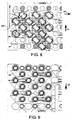
- FIGS. 6-9 The operation of one of the grid cells of the diverting conveyor system is illustrated in FIGS. 6-9 .
- Each gear plate controls an array of 18 diverting rollers. (Three diverting rollers are omitted at the lower left of FIGS. 6 and 8 to illustrate features of the gear plate better.)
- FIGS. 6 and 7 the gear plate 64 is shown translated to an intermediate position in which the diverting roller cartridges 48 are positioned in the middle of the elongated slots 68. With the cartridges rotated to this position, the axes of rotation 104 of the diverting rollers in the grid cell are perpendicular, at right angles, to the direction of belt travel 32.
- the diverting rollers in this orientation rotate in the direction of belt travel and the perpendicularly disposed engaged belt rollers ride along the diverting rollers without rotation.
- the belt rollers are deactuated when the diverting rollers are in the orientation of FIGS. 6 and 7 .
- the gear plate is translated over its range to one extreme with the cartridges positioned at one end of the elongated slots 68 in FIGS. 8 and 9 , the axes of rotation 104 of the diverting rollers form an acute angle y measured clockwise from the direction of belt travel.
- the diverting rollers rotate in the direction of arrow 106, and the belt rollers rotate in the direction of arrow 108 to push conveyed objects toward the right of FIG. 8 , as indicated by the arrow 34 in FIG. 3 .
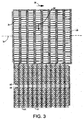
- the outbound singulating conveyor 22 preferably includes a modular plastic conveyor belt 110 having actuated oblique rollers 112.
- the rollers on each half of the belt rotate in a direction angled toward the center of the belt as indicated by arrows 114 and 115.
- Packages conveyed atop the singulating belt are driven to the center of the belt as it advances in the direction of belt travel 32.
- the singulating belt runs faster than the sorting belt to increase the separation between consecutive packages along the center line of the singulating conveyor.
- the singulating conveyor aligns the packages in a single file for delivery downstream, as illustrated in FIG. 2 .
- the singulating belt may be constructed of Intralox ® Series 400 angled roller modules and supported on bearing surfaces, such as a carryway pan, that actuate the oblique belt rollers along the length of the carryway as the belt advances.
- each package is sensed by a sensor, such as a digital camera 116 supported above the entrance to the sorting conveyor as shown in FIGS. 1 and 2 .
- a sensor such as a digital camera 116 supported above the entrance to the sorting conveyor as shown in FIGS. 1 and 2 .
- Other means for sensing the size and position of each package such as laser or acoustic systems, may alternatively be used.
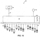
- the video images 117 taken by the camera are fed to a control system 118 including a system controller 119 as shown in FIG.10 .
- the system controller includes a programmable computer, such as a work station, a desktop computer, a programmable logic controller, or an embedded microcontroller.
- the system controller uses the video images, which are taken at regular intervals, to produce a table of trajectories 120 for each package that is received on the sorting conveyor.
- the computed trajectories are used to selectively actuate the belt rollers passing through each grid cell to cause the packages to follow their computed trajectories on the sorting conveyor.
- the actuators 86 for the individual grid cells are controlled over signal lines 121 by an output module 122.
- the actuators are labeled A 11 -A 85 in FIG. 10 to indicate a grid of 8 rows by 5 columns, or 40 grid cells.
- the output modules, the actuators, and the rack-and-pinion system form means for selectively controlling each grid cell.
- the speed of the sorting belt is also needed to compute the trajectory. The speed may be sensed by a tachometer 124 or other sensor and reported to the system controller. Alternatively, the speed setting of the sorting conveyor's drive motor may be used by the controller in computing the trajectories.
- a control sequence software routine runs regularly every T seconds, for example, every 0.5 seconds. As indicated in step 124 of the flowchart, the sequence starts by taking a video image of the incoming package flow. If the controller determines, as in step 126, that a new package, i.e., one not already assigned a trajectory, is entering the sorting conveyor, it determines that package's size, or footprint, and its position on the conveyor as indicated in step 128. The controller then determines the belt speed from a sensor or from a setpoint or a predetermined value as in step 130.
- the controller computes a trajectory for each newly entering package (step 132) and saves it in a trajectory table.
- Each trajectory defines which grid cells are to be actuated for the associated package during consecutive actuation intervals beginning with the interval during which the package enters the sorting conveyor.
- FIGS. 11A-11E provide an example of the operations for two packages P 1 and P 2 .
- Each figure represents the actuation status of each grid cell in consecutive intervals beginning at interval start time T 1 in FIG. 11A .
- T is the repetition rate of the control sequence.
- the Grid Control Task uses the trajectories to determine which grid cells to actuate during the time interval (step 136) and sends corresponding actuate/deactuate signals to the cell actuators (step 138).
- No grid cells are initially actuated for the package P 2 so that it may continue moving in the direction of belt travel without interfering with the package P 1 .
- grid cells G 11 , G 21 , G 22 , and G 31 are actuated to continue to divert the package P 1 toward the singulating conveyor along the trajectory J 1 .
- grid cells G 33 and G 34 are actuated to start to divert P 2 along its trajectory J 2 .
- T 3 to T 4 FIG. 11C
- Grid cells G 42 , G 52 , and G 53 are actuated to continue to urge P 2 along its trajectory.
- T 4 to T 5 FIG. 11D
- grid cells G 16 and G 11 are actuated to complete the transfer of P 2 to the singulating conveyor. Because P 1 has already been transferred, no grid cells are actuated for it.
- T 5 to T 6 FIG. 11E ), no grid cells are actuated because both packages have already been transferred.
- the trajectories for each package may be represented by an indexed array of 5 ⁇ 8 matrices of 1's and 0's, where each matrix element corresponds to one of the grid cells and a "1" indicates actuate and a "0" deactuate.
- the index of each matrix in the array corresponds to the start of the corresponding time interval.
- the matrices of all the trajectories are logically or'ed together for each index to determine the overall grid-cell actuation map during each interval.
- the map defines the actuate/deactuate states of the control lines 121 ( FIG. 10 ) to the actuators.
- each interval is initiated by the execution of the control sequence, which first images the incoming flow and bids the Grid Control Task to output the actuation signal according to the trajectories. If no new entering packages are detected, the control sequence bypasses the trajectory computation by following the bypass path 140 in the control sequence and proceeds directly to bid the Grid Control Task to run.
- control sequence software provides means for computing the trajectory for each article, or package, to achieve a rapid and orderly transfer of packages off the side of the sorting conveyor without collisions between packages.
- the rollers in the sorting conveyor belt could be selectively actuated by mechanisms or systems other than the array of diverting rollers underlying the belt.
- the rollers could be made to be magnetically actuated to selectively rotate in each grid cell by electromagnets forming the control elements for the grid.
- each belt roller could include a rotor selectively rotated by an array of individually controlled stators serving as control elements positioned along the carryway and defining the grid cells.
- the conveyor belt could be dispensed with and articles directly atop the diverting rollers diverted across the sorting conveyor if the diverting rollers were motor-driven rollers individually controlled to rotate or change direction.
- the flowchart represents one example of a routine controlling the actuation of the grid cells according to computed package trajectories.
- Other software implementations are possible.
- the visioning step and the grid control step could be performed at different rates.
- the trajectory table could be arranged other than as an array of matrices.
Landscapes
- Engineering & Computer Science (AREA)
- Mechanical Engineering (AREA)
- Branching, Merging, And Special Transfer Between Conveyors (AREA)
- Discharge Of Articles From Conveyors (AREA)
- Rollers For Roller Conveyors For Transfer (AREA)
- Chain Conveyers (AREA)
- Attitude Control For Articles On Conveyors (AREA)
Description
- The invention relates generally to power-driven conveyors and, more particularly, to a sorting system using a conveyor belt having article-supporting rollers that are selectively rotated in individual control cells arranged in a grid through which the belt passes.
- Shoe sorters, pusher bars, and diverting rails are used to sort packages and other articles on a conveyor. In high-density package flows, it is often necessary to unscramble side-by-side packages before sorting to prevent one package from blocking another's exit off the conveyor. But a conveyor used to unscramble packages before they are diverted takes up space. And unscrambling packages of various sizes and orientation in a mass flow is difficult, especially at high throughput rates.
- Thus, there is a need for a sorter that can sort a variety of package sizes at a high throughput rate without taking up too much floor space.
-
WO 00/76887 A1 - This need and other needs are addressed by a sorting system embodying features of the invention including a sorting conveyor according to claim 1 with a control system. The sorting conveyor includes a conveyor belt that advances in the direction of belt travel. The belt has article-supporting belt rollers that can rotate in a direction transverse to the direction of belt travel. The sorting conveyor also includes control elements arranged in a grid of multiple rows and columns of individually controlled grid cells. The control elements selectively rotate the belt rollers as they pass through the grid cells. A control system includes means for sensing the size and position of each article entering the belt. A trajectory along the conveyor belt is computed for each article based on its size and position on entering the belt by means for computing a trajectory. Each grid cell is selectively controlled according to the trajectories to divert articles transversely across the sorting conveyor along the trajectories.
- In another aspect of the invention, a method for sorting a flow of articles according to claim 9 comprises:
- (a) receiving a flow of articles atop belt rollers in a conveyor belt advancing in a direction of belt travel; (b) imaging the articles to determine their sizes and positions on entering the conveyor belt; (c) computing a trajectory for each article from its size and position; (d) selectively actuating the belt rollers to rotate transverse to the direction of belt travel according to the trajectories. In this way, articles are diverted across the conveyor belt along the trajectories.
- Another version of the sorting conveyor includes a sorting conveyor that has rollers arranged in a grid of multiple rows and columns of individually controlled grid cells. A control system determines the size and position of each article entering the sorting conveyor, computes a trajectory for each article along the sorting conveyor from the article's size and position, and selectively controls the rollers in each grid cell according to the trajectories computed for the articles to actuate the rollers to divert articles across the sorting conveyor along the trajectories.
- These features and aspects of the invention, as well as its advantages, are better understood by referring to the following description, appended claims, and accompanying drawings, in which:
-
FIG. 1 is an isometric pictorial of a sorting system embodying features of the invention; -
FIG. 2 is a top plan of the sorting system ofFIG. 1 ; -
FIG. 3 is a top plan view of a portion of the sorting conveyor in the sorting system ofFIG. 1 ; -
FIG. 4 is a partly exploded top isometric view of an actuation grid for a sorting system as inFIG. 1 ; -
FIG. 5 is a bottom isometric view of the actuation grid ofFIG. 4 ; -
FIG. 6 is an enlarged top plan view of a grid cell of the actuation grid ofFIG. 4 in a deactuated position; -
FIG. 7 is an enlarged bottom view of the grid cell ofFIG. 6 in a deachiated position; -
FIG. 8 is an enlarged top plan view as inFIG. 6 with the grid cell in an actuated position; -
FIG. 9 is an enlarged view as inFIG. 7 with the grid cell in an actuated position; -
FIG. 10 is a block diagram of a control system usable in the sorting system ofFIG. 1 ; -
FIGS. 11A-11E illustrate the control sequence for one example arrangement of packages on the sorting conveyor in the sorting system ofFIG. 1 ; and -
FIG. 12 is a flowchart of one version of control logic usable in the control system of the sorting system ofFIG. 1 . - A sorting system embodying features of the invention is shown in
FIGS. 1 and 2 . An incoming mass flow of a variety of articles, such as boxes or packages P, is sorted in asorting conveyor 20 and transferred onto an abutting outbound singulatingconveyor 22. The mass flow of packages, randomly oriented and positioned, is fed onto the sorting conveyor by an infeedconveyor 24 advancing in aconveying direction 26. The infeed conveyor may be realized as a powered roller conveyor, a flat belt, a modular conveyor belt, a chute, or the like. The sorting conveyor comprises aconveyor belt 28 having package-supporting rollers 30 (FIG. 3 ) arranged to rotate onaxes 31 perpendicular, or transverse, to the direction ofbelt travel 32, which is in the conveying direction. The package-supporting belt rollers may be actively rotated in the direction of arrow 34 to divert packages toward thesingulating conveyor 22. - The transverse rollers in the sorting-
conveyor belt 28 are selectively rotated in agrid 36 of individually actuated zones, orgrid cells 38, arranged in rows R and columns C along the sorting conveyor's carryway. In one embodiment, therollers 30 in the sorting-conveyor belt 28 extend through the thickness of the belt so that they can be rotated by rolling contact with bearing surfaces underlying the belt as the belt advances in the direction of belt travel. One example of such a belt is the Intralox® Series 7000 belt manufactured and sold by Intralox, L.L.C. of Harahan, Louisiana, U.S.A. - An exploded view of a portion of the bearing surfaces underlying the belt is shown in
FIG. 4 . The belt rollers are supported atop an array of control elements-in this example,diverting rollers 40 positioned along the carryway. The peripheral surfaces of the diverting rollers serve as the bearing surfaces. - The diverting rollers are mounted on a
carryway pan 42, which is itself mounted in a conveyor frame (not shown). The pan is perforated with a plurality ofcircular openings 44 arranged inlongitudinal columns 46 and lateral, or transverse,rows 47. The columns of openings are laterally aligned with the lateral positions of the belt rollers. Each opening rotatably receives acartridge 48 supporting a freely rotatablediverting roller 40, which engages the belt rollers in the corresponding column as the belt advances in the direction of belt travel. The rolling contact between the belt rollers and the diverting rollers causes them both to roll on each other and rotate as long as their axes are oblique to each other. - The
diverting roller cartridge 48 includes a retainer ring 50 with diametrically opposite holes 52 supporting the ends of an axle received in a bore in thediverting roller 40. One of the holes can be a through hole through which the axle can be inserted into the cartridge and the diverting roller, and the other hole can have a blind end forming an end stop for the axle. In this way, the diverting roller is retained in the cartridge along a fixed axis with a salient portion of the roller protruding beyond the top of the retainer ring. Extending downward from the retainer ring encircling the diverting roller is anupper journal stem 54 having a cylindrical outer periphery indented inward from the ring to form ashoulder 56 between the peripheries of the ring and the stem. A lower journal stem 58 distal from the retainer ring has a smaller diameter than the upper journal stem. The periphery of the lower journal stem is indented inward of the periphery of the upper journal stem. Acartridge gear 60 is disposed between the upper stem and the lower stem. The cartridge gear is preferably a spur gear with peripheral teeth whose tips do not extend past the periphery of the upper journal stem. - The
cartridges 48 are received in theopenings 44 in the carryway pan as shown inFIG. 4 . The walls of the openings form bearingsurfaces 62 against which the upper journal stems can rotate. Because the diameter of the retainer rings exceeds the diameter of the openings, the ring'sshoulder 56 rests atop the carryway pan with the smaller-diameter stems and gear portions suspended below. - A plurality of
gear plates 64 are movably positioned below the carryway pan. Each gear plate defines one of the individually actuatable grid cells. Actuated gears in the form of rack gears 66 are disposed on the gear plates. Each rack gear is positioned to engage the teeth of one of the cartridge gears to form a rack-and-pinion system that can rotate its cartridges in unison as the gear plate is translated. The gear plate has elongated openings 68 bounded on one side by a linear array of teeth 70 forming a rack gear. Each elongated opening 68 is positioned below one of theopenings 44 in the carryway pan. The lower journal stem extends through the elongated openings in the gear plates, which are sandwiched between two other plates: thecarryway pan 42 and abottom plate 72. The bottom plate, which is stationarily affixed to a portion of the conveyor frame, has a plurality ofopenings 74 vertically aligned with, but having a smaller diameter than, the openings in the carryway pan. Theopenings 74 are sized to rotatably receive the lower journal stems 58 of the cartridges. This helps align the upper and lower support plates to facilitate assembly of the roller drive mechanism and also confines the rotatable cartridges in rotation on fixed vertical axes. - Confronting
spacer pads 76 on the top of thebottom plate 72 and on the bottom of thetop plate 42 maintain the proper spacing between the two plates and themovable gear plates 64.Spacers 78, fastened bybolts 80,washers 82, and nuts 84, maintain the spacing between the carryway pan and thebottom plate 72. - Each
gear plate 64 is translated by an individuallinear actuator 86, such as an air cylinder, an electrical actuator, or a mechanical actuator. As shown inFIG. 5 , actuators in each grid cell column are attached at one end to a mountingbracket 88 mounted to the bottom of thebottom plate 72 by acoupling 90. The extension of anextension rod 92 from the other end of the actuator is connected by a coupling 94 to an actuator plate 96. Three internally threadedposts 98 extend upward from the actuator plate throughslots 100 in the bottom plate. Three flathead screws 102 extend through thegear plate 64 into the posts to attach the gear plate to the associated actuator plate. The extension rod translates the actuator plate and the gear plate, the rod's extension determining the position of the gear plate and the orientation of the diverting rollers. - The operation of one of the grid cells of the diverting conveyor system is illustrated in
FIGS. 6-9 . Each gear plate controls an array of 18 diverting rollers. (Three diverting rollers are omitted at the lower left ofFIGS. 6 and8 to illustrate features of the gear plate better.) InFIGS. 6 and 7 , thegear plate 64 is shown translated to an intermediate position in which the divertingroller cartridges 48 are positioned in the middle of the elongated slots 68. With the cartridges rotated to this position, the axes ofrotation 104 of the diverting rollers in the grid cell are perpendicular, at right angles, to the direction ofbelt travel 32. As the conveyor belt advances in the direction of belt travel, the diverting rollers in this orientation rotate in the direction of belt travel and the perpendicularly disposed engaged belt rollers ride along the diverting rollers without rotation. Thus, the belt rollers are deactuated when the diverting rollers are in the orientation ofFIGS. 6 and 7 . When the gear plate is translated over its range to one extreme with the cartridges positioned at one end of the elongated slots 68 inFIGS. 8 and 9 , the axes ofrotation 104 of the diverting rollers form an acute angle y measured clockwise from the direction of belt travel. In this orientation, the diverting rollers rotate in the direction ofarrow 106, and the belt rollers rotate in the direction ofarrow 108 to push conveyed objects toward the right ofFIG. 8 , as indicated by the arrow 34 inFIG. 3 . - As shown in
FIG. 3 , theoutbound singulating conveyor 22 preferably includes a modular plastic conveyor belt 110 having actuated oblique rollers 112. The rollers on each half of the belt rotate in a direction angled toward the center of the belt as indicated by arrows 114 and 115. Packages conveyed atop the singulating belt are driven to the center of the belt as it advances in the direction ofbelt travel 32. Preferably, the singulating belt runs faster than the sorting belt to increase the separation between consecutive packages along the center line of the singulating conveyor. Thus, the singulating conveyor aligns the packages in a single file for delivery downstream, as illustrated inFIG. 2 . The singulating belt may be constructed of Intralox® Series 400 angled roller modules and supported on bearing surfaces, such as a carryway pan, that actuate the oblique belt rollers along the length of the carryway as the belt advances. - The size and position of each package are sensed by a sensor, such as a
digital camera 116 supported above the entrance to the sorting conveyor as shown inFIGS. 1 and 2 . Other means for sensing the size and position of each package, such as laser or acoustic systems, may alternatively be used. Thevideo images 117 taken by the camera are fed to acontrol system 118 including asystem controller 119 as shown inFIG.10 . The system controller includes a programmable computer, such as a work station, a desktop computer, a programmable logic controller, or an embedded microcontroller. The system controller uses the video images, which are taken at regular intervals, to produce a table oftrajectories 120 for each package that is received on the sorting conveyor. The computed trajectories are used to selectively actuate the belt rollers passing through each grid cell to cause the packages to follow their computed trajectories on the sorting conveyor. Theactuators 86 for the individual grid cells are controlled oversignal lines 121 by anoutput module 122. The actuators are labeled A11-A85 inFIG. 10 to indicate a grid of 8 rows by 5 columns, or 40 grid cells. The output modules, the actuators, and the rack-and-pinion system form means for selectively controlling each grid cell. The speed of the sorting belt is also needed to compute the trajectory. The speed may be sensed by atachometer 124 or other sensor and reported to the system controller. Alternatively, the speed setting of the sorting conveyor's drive motor may be used by the controller in computing the trajectories. - The operation of the sorting conveyor is illustrated in
FIG. 11A-11E in conjunction with the flowcharts inFIG. 12 . A control sequence software routine runs regularly every T seconds, for example, every 0.5 seconds. As indicated instep 124 of the flowchart, the sequence starts by taking a video image of the incoming package flow. If the controller determines, as instep 126, that a new package, i.e., one not already assigned a trajectory, is entering the sorting conveyor, it determines that package's size, or footprint, and its position on the conveyor as indicated instep 128. The controller then determines the belt speed from a sensor or from a setpoint or a predetermined value as instep 130. From the footprint, position, and speed data, the controller computes a trajectory for each newly entering package (step 132) and saves it in a trajectory table. Each trajectory defines which grid cells are to be actuated for the associated package during consecutive actuation intervals beginning with the interval during which the package enters the sorting conveyor. -
FIGS. 11A-11E provide an example of the operations for two packages P1 and P2. Each figure represents the actuation status of each grid cell in consecutive intervals beginning at interval start time T1 inFIG. 11A . The other start times are: T2=T1+T; T3 = T2 + T; T4 = T3 + T; T5 = T4 + T, where T is the repetition rate of the control sequence. During the first interval from T1 to T2 (FIG. 11A ), only grid cells G11 and G12, as indicated by the shaded cells, are actuated to start the package P1 on its trajectory J1. This is indicated by step 134 of the flowchart inFIG. 12 , which bids a Grid Control Task to run. The Grid Control Task uses the trajectories to determine which grid cells to actuate during the time interval (step 136) and sends corresponding actuate/deactuate signals to the cell actuators (step 138). No grid cells are initially actuated for the package P2 so that it may continue moving in the direction of belt travel without interfering with the package P1. During the next interval, from T2 to T3 (FIG. 11B ), grid cells G11, G21, G22, and G31 are actuated to continue to divert the package P1 toward the singulating conveyor along the trajectory J1. In the meantime, because the package P2 is now largely laterally separated enough from P1, grid cells G33 and G34 are actuated to start to divert P2 along its trajectory J2. During the next interval, T3 to T4 (FIG. 11C ), only grid cell G41 is actuated for P1, which is almost entirely transferred off the sorting conveyor. Grid cells G42, G52, and G53 are actuated to continue to urge P2 along its trajectory. During the next interval, T4 to T5 (FIG. 11D ), grid cells G16 and G11 are actuated to complete the transfer of P2 to the singulating conveyor. Because P1 has already been transferred, no grid cells are actuated for it. Finally, during the final interval shown, T5 to T6 (FIG. 11E ), no grid cells are actuated because both packages have already been transferred. - As the example suggests, the trajectories for each package may be represented by an indexed array of 5 × 8 matrices of 1's and 0's, where each matrix element corresponds to one of the grid cells and a "1" indicates actuate and a "0" deactuate. The index of each matrix in the array corresponds to the start of the corresponding time interval. The matrices of all the trajectories are logically or'ed together for each index to determine the overall grid-cell actuation map during each interval. The map defines the actuate/deactuate states of the control lines 121 (
FIG. 10 ) to the actuators. - As indicated by the flowchart in
FIG. 12 , each interval is initiated by the execution of the control sequence, which first images the incoming flow and bids the Grid Control Task to output the actuation signal according to the trajectories. If no new entering packages are detected, the control sequence bypasses the trajectory computation by following thebypass path 140 in the control sequence and proceeds directly to bid the Grid Control Task to run. - Thus, the control sequence software provides means for computing the trajectory for each article, or package, to achieve a rapid and orderly transfer of packages off the side of the sorting conveyor without collisions between packages.
- Although the invention has been described in detail with respect to a single version, other versions are possible. For example, the rollers in the sorting conveyor belt could be selectively actuated by mechanisms or systems other than the array of diverting rollers underlying the belt. As one example, the rollers could be made to be magnetically actuated to selectively rotate in each grid cell by electromagnets forming the control elements for the grid. Or each belt roller could include a rotor selectively rotated by an array of individually controlled stators serving as control elements positioned along the carryway and defining the grid cells. Furthermore, the conveyor belt could be dispensed with and articles directly atop the diverting rollers diverted across the sorting conveyor if the diverting rollers were motor-driven rollers individually controlled to rotate or change direction. The flowchart represents one example of a routine controlling the actuation of the grid cells according to computed package trajectories. Other software implementations are possible. For example, the visioning step and the grid control step could be performed at different rates. And the trajectory table could be arranged other than as an array of matrices.
Claims (11)
- A sorting system comprising:a sorting conveyor (20) including:a plurality of selectively rotatable rollers arranged in a grid (36) of multiple rows (R) and columns (C) of individually controlled grid cells (38) along the sorting conveyor (20); characterised in that the system comprises:a conveyor belt (28) advancing in a direction of belt travel (32) and having a plurality of article- supporting belt rollers (30) extending through the thickness of the conveyor belt (28) and rotatable in a direction transverse to the direction of belt travel and wherein the selectively rotatable rollers have bearing surfaces contacting and selectively rotating the belt rollers (30) passing through the grid cells;a control system (118) which determines the size and position of each article (P1; P2) on entering the sorting conveyor (20), and which computes a trajectory for each article along the sorting conveyor (20) from the article's entry to its exit from the sorting conveyor from the article's size and position, and which selectively controls the rollers in each grid cell according to the trajectories computed for the articles to actuate and deactuate the rollers to divert articles across the sorting conveyor along the computed trajectories.
- A sorting system as in claim 1 wherein the control system (118) comprises at least one camera (116) providing an image (117) of the articles.
- A sorting system as in claim 1 wherein the control system (118) computes non-interfering trajectories for articles entering the conveyor belt side by side.
- A sorting system as in claim 1 wherein the control system (118) computes trajectories as a function of belt speed in the direction of belt travel.
- A sorting system as in claim 1 wherein the control system includes an actuator (86) associated with each grid cell that selectively changes the angle of all the selectively rotatable rollers in the grid cell with respect to the belt rollers.
- A sorting system as in claim 5 wherein the belt rollers rotate on axes parallel to the direction of belt travel and the actuators (86) change the angle of all the diverting rollers (40) in the grid cell from an oblique angle causing the belt rollers to rotate by contact to a right angle disabling rotation of the belt rollers.
- A sorting system as in claim 1 further comprising an outbound conveyor (22) advancing in the direction of belt travel at a greater speed than and abutting the sorting conveyor side by side along a portion of the length of the sorting conveyor to receive articles diverted from the sorting conveyor and accelerate the articles along the outbound conveyor in the direction of belt travel in single file.
- A sorting system as in claim 1 wherein the control system saves a trajectory for each newly entering article in a trajectory table.
- A method for sorting a flow of articles with the system according to claim 1, comprising:receiving a flow of articles atop belt rollers in a conveyor belt advancing in a direction of belt travel;imaging the articles to determine their size and positions on entering the conveyor belt;computing a trajectory for each article along the conveyor belt from the article's entry to its exit from the conveyor belt as a function of its size and position;selectively actuating and deactuating the belt rollers to rotate transverse to the direction of belt travel according to the trajectories to divert the articles across the conveyor belt along the trajectories.
- The method of claim 9 further comprising establishing a stationary grid of individually controlled grid cells along the conveyor belt to selectively actuate the belt rollers passing pass through the grid cells.
- The method of claim 9 comprising saving a trajectory for each newly entering article in a trajectory table.
Applications Claiming Priority (2)
| Application Number | Priority Date | Filing Date | Title |
|---|---|---|---|
| US12/509,207 US20110022221A1 (en) | 2009-07-24 | 2009-07-24 | Roller-belt sorter with control grid |
| PCT/US2010/041124 WO2011011195A1 (en) | 2009-07-24 | 2010-07-07 | Roller-belt sorter with control grid |
Publications (2)
| Publication Number | Publication Date |
|---|---|
| EP2456693A1 EP2456693A1 (en) | 2012-05-30 |
| EP2456693B1 true EP2456693B1 (en) | 2016-08-17 |
Family
ID=42790997
Family Applications (1)
| Application Number | Title | Priority Date | Filing Date |
|---|---|---|---|
| EP10730961.9A Active EP2456693B1 (en) | 2009-07-24 | 2010-07-07 | Roller-belt sorter with control grid |
Country Status (8)
| Country | Link |
|---|---|
| US (1) | US20110022221A1 (en) |
| EP (1) | EP2456693B1 (en) |
| JP (1) | JP5732052B2 (en) |
| KR (1) | KR20120089636A (en) |
| CN (1) | CN102470989B (en) |
| BR (1) | BR112012001211B1 (en) |
| IN (1) | IN2012DN01582A (en) |
| WO (1) | WO2011011195A1 (en) |
Cited By (1)
| Publication number | Priority date | Publication date | Assignee | Title |
|---|---|---|---|---|
| EP3153242B1 (en) | 2015-10-09 | 2022-12-28 | Deutsche Post AG | Actuation of a conveying system |
Families Citing this family (42)
| Publication number | Priority date | Publication date | Assignee | Title |
|---|---|---|---|---|
| DE102010015584A1 (en) * | 2010-04-19 | 2011-10-20 | SSI Schäfer Noell GmbH Lager- und Systemtechnik | Matrix conveyor for use as sorter or palletizer |
| KR101341421B1 (en) | 2011-12-19 | 2013-12-13 | 신상철 | method and apparatus for sectiomal loading of fabric |
| US8978879B2 (en) * | 2012-01-31 | 2015-03-17 | Laitram, L.L.C. | Multi-directional roller assembly |
| DK2882650T3 (en) | 2012-08-13 | 2021-12-20 | Laitram Llc | PACKAGE HANDLING PROCEDURE |
| US9499341B2 (en) * | 2012-10-25 | 2016-11-22 | Intelligrated Headquarters Llc | Transmission having variable output orientation |
| DE102013206790A1 (en) * | 2013-04-16 | 2014-10-16 | Deutsche Post Ag | package singulation |
| US9073704B2 (en) * | 2013-09-09 | 2015-07-07 | Laitram, L.L.C. | Conveyor employing a vacuum |
| US9511953B1 (en) * | 2013-09-26 | 2016-12-06 | Amazon Technologies, Inc. | Singulators with ports for diverting items |
| US9745143B2 (en) * | 2013-10-25 | 2017-08-29 | Intelligrated Headquarters, Llc | Pitch independent divert drive |
| US9108807B1 (en) * | 2013-12-17 | 2015-08-18 | Amazon Technologies, Inc. | Linear induction motor-driven divert mechanisms |
| US9079717B1 (en) * | 2014-01-09 | 2015-07-14 | Laitram, L.L.C. | Conveyor systems for diverting objects |
| EP3099607B1 (en) * | 2014-01-27 | 2021-06-30 | Laitram, L.L.C. | Induction conveyor |
| WO2015171851A1 (en) * | 2014-05-08 | 2015-11-12 | Laitram, L.L.C. | Touchless guide device for a conveyor |
| KR101536081B1 (en) * | 2014-10-21 | 2015-07-10 | 아진산업(주) | Method for loading material for press system |
| US9352908B1 (en) * | 2014-12-03 | 2016-05-31 | Laitram, L.L.C. | Stacked-roller belt conveyor with zone control |
| CN105035718A (en) * | 2015-06-30 | 2015-11-11 | 伯曼机械制造(上海)有限公司 | Box conveying converging system for saving crossing space |
| EP3203264B1 (en) * | 2016-02-04 | 2024-08-28 | Mettler-Toledo GmbH | Method of imaging an object for tracking and documentation during transportation and storage |
| EP3459881A4 (en) | 2016-05-19 | 2020-01-15 | Itoh Denki Co., Ltd. | Conveying device |
| US10059522B2 (en) * | 2016-11-04 | 2018-08-28 | Laitram, L.L.C. | Divert chutes in sorting-conveyor systems |
| KR101920395B1 (en) | 2017-01-23 | 2018-11-20 | 주식회사 가치소프트 | Automated article singulator and method thereof |
| CN110636981B (en) | 2017-03-08 | 2021-10-26 | 雷勃美国公司 | Package sorting and conveying module and system and method thereof |
| US10532894B2 (en) | 2017-03-10 | 2020-01-14 | Regal Beloit America, Inc. | Modular transfer units, systems, and methods |
| US10899564B2 (en) | 2017-07-14 | 2021-01-26 | Laitram, L.L.C. | Destacking conveyor |
| CN107187654A (en) * | 2017-07-14 | 2017-09-22 | 无锡市荣景晨机械有限公司 | Sausage sequence counting device |
| EP3713857B1 (en) | 2017-11-22 | 2024-07-24 | Regal Beloit America, Inc. | Modular sortation units, systems, and methods |
| JP7057597B2 (en) * | 2017-12-28 | 2022-04-20 | 伊東電機株式会社 | Transport device and transport method |
| KR20200002383A (en) * | 2018-06-29 | 2020-01-08 | 주식회사 가치소프트 | Automated article sorter capable of sorting articles without the alignment in a line and method thereof |
| WO2020058736A1 (en) * | 2018-09-19 | 2020-03-26 | Gebo Cermex Canada Inc. | Device and method for conveying products |
| CN109368223A (en) * | 2018-10-16 | 2019-02-22 | 无锡弘宜智能科技有限公司 | Mixing package linear separation device |
| EP3837194A4 (en) * | 2018-10-22 | 2022-08-10 | Laitram, L.L.C. | Grid sorter |
| AU2019365257B2 (en) * | 2018-10-24 | 2023-12-07 | Dematic Corp. | Positive displacement sorter with parallel divert and diagonal discharge |
| US11066242B2 (en) | 2018-10-24 | 2021-07-20 | Dematic Corp. | Positive displacement sorter with parallel divert and diagonal discharge |
| JP7134073B2 (en) * | 2018-11-14 | 2022-09-09 | 株式会社ダイフク | Goods loading equipment |
| EP3953067A4 (en) * | 2019-04-10 | 2022-12-21 | Laitram, LLC | Package detection and intelligent sorting |
| CN113727925A (en) * | 2019-05-24 | 2021-11-30 | 莱特拉姆有限责任公司 | Compact sorting machine |
| CN110386430B (en) * | 2019-07-23 | 2024-09-03 | 科捷智能科技股份有限公司 | Single-order arrangement device and method thereof |
| US10815069B1 (en) * | 2019-08-19 | 2020-10-27 | Siemens Logistics Llc | Parcel singulation systems and methods |
| CN110961361B (en) * | 2019-11-25 | 2023-10-20 | 科捷智能科技股份有限公司 | Side-by-side wrapped separator and method thereof |
| EP4143109A2 (en) * | 2020-07-21 | 2023-03-08 | Laitram, L.L.C. | Conveyor system for selectively diverting objects |
| KR102550044B1 (en) * | 2021-06-07 | 2023-07-04 | 주식회사 가치소프트 | Singulator and method for singulating |
| CN113979090A (en) * | 2021-11-24 | 2022-01-28 | 广东邦普循环科技有限公司 | Battery conveyer belt |
| CN114408547B (en) * | 2021-12-24 | 2023-04-07 | 广东顺力智能物流装备股份有限公司 | Jacking type orientation adjustment goods shelf manipulator for intelligent logistics and application method thereof |
Citations (2)
| Publication number | Priority date | Publication date | Assignee | Title |
|---|---|---|---|---|
| EP1375389A1 (en) * | 2002-06-20 | 2004-01-02 | Asahi-Seiki Manufacturing Co., Ltd | Conveying apparatus and conveying system |
| DE102004022060A1 (en) * | 2004-05-05 | 2005-12-01 | Siemens Ag | Conveyor unit for transporting of goods has top surface of carrying surface provided with micro-mechanical elements which for transporting of goods along conveyor unit execute controlled micro-movements |
Family Cites Families (29)
| Publication number | Priority date | Publication date | Assignee | Title |
|---|---|---|---|---|
| US3679043A (en) * | 1971-04-13 | 1972-07-25 | Webb Co Jervis B | Roller transfer conveyor |
| DE3611926A1 (en) * | 1986-04-09 | 1987-10-22 | Farkas Ingbuero | Method for dry screening products mixed with one another and apparatus for carrying out the method |
| US5074405A (en) * | 1989-04-25 | 1991-12-24 | Fmc Corporation | Right angle transfer deck |
| US5145049A (en) * | 1990-10-12 | 1992-09-08 | Mcclurkin Jack | Pattern forming conveyor |
| JPH0713822U (en) * | 1993-08-16 | 1995-03-10 | 株式会社フクダ企画 | Sorting machine |
| JPH10258927A (en) * | 1997-03-17 | 1998-09-29 | Fuji Seal Co Ltd | Carrying method for container and device thereof |
| JP3349084B2 (en) * | 1998-01-29 | 2002-11-20 | 株式会社椿本チエイン | Branch sorting equipment for goods |
| US6044956A (en) * | 1998-07-01 | 2000-04-04 | Fki Industries, Inc. | Sortation conveyor system for high friction articles |
| US6494312B2 (en) * | 1998-11-02 | 2002-12-17 | The Laitram Corporation | Modular roller-top conveyor belt with obliquely-arranged rollers |
| DE19927251C2 (en) * | 1999-06-15 | 2001-05-17 | Siemens Ag | Device for handling piece goods |
| US6318544B1 (en) * | 1999-11-05 | 2001-11-20 | The Laitram Corporation | Changing the characteristics of an article-conveying belt surface on a running conveyor |
| US6910569B2 (en) * | 2002-01-29 | 2005-06-28 | Siemens Technology-To-Business Center, Llc | Load singulation system and method |
| US6758323B2 (en) * | 2002-05-30 | 2004-07-06 | The Laitram Corporation | Singulating conveyor |
| DE60320572T2 (en) * | 2002-10-29 | 2009-06-04 | Siemens Aktiengesellschaft | CONVEYOR DEVICE HANDLING THE DISTRIBUTED ARTICLE |
| US7040478B2 (en) * | 2003-08-05 | 2006-05-09 | Rapistan Systems Advertising Corp. | Steerable diverter system |
| US6968941B2 (en) * | 2003-11-21 | 2005-11-29 | Materials Handling Systems, Inc. | Apparatus and methods for conveying objects |
| JP2005343679A (en) * | 2004-06-07 | 2005-12-15 | Maruyasu Kikai Kk | Circulation type alignment conveyance device |
| US7007792B1 (en) * | 2005-03-08 | 2006-03-07 | Laitram, L.L.C. | Angled-roller article-rotating belt conveyor |
| US7191894B2 (en) * | 2005-04-04 | 2007-03-20 | Laitram, L.L.C. | Variable angled-roller belt and conveyor |
| US7249671B2 (en) * | 2005-05-06 | 2007-07-31 | Laitram, L.L.C. | Roller-belt conveyor for accumulating and moving articles laterally across the conveyor |
| US7344018B2 (en) * | 2005-05-06 | 2008-03-18 | Laitram, L.L.C. | Conveyor and method for diverting closely spaced articles |
| BRPI0621100A2 (en) * | 2005-11-21 | 2011-11-29 | Laitram Llc | switch and switch for distributing articles received from an inbound conveyor belt to a plurality of outbound conveyor belts |
| GB2434569B (en) * | 2006-01-25 | 2008-01-23 | Herbert R J Eng Ltd | Conveyor |
| US7971701B2 (en) * | 2006-01-26 | 2011-07-05 | Laitram, L.L.C. | Diagonal sorter |
| US7506751B2 (en) * | 2006-01-26 | 2009-03-24 | Laitram, L.L.C. | Conveyor systems for diverting objects |
| US7461739B2 (en) * | 2006-01-26 | 2008-12-09 | Laitram, L.L.C. | Systems and methods for diverting objects |
| US7284653B2 (en) * | 2006-03-23 | 2007-10-23 | Laitram, L.L.C. | Sorter belt conveyor |
| EP1999046A1 (en) * | 2006-03-27 | 2008-12-10 | Intellegrated, Inc. | Unscrambling conveyor |
| DE502006001611D1 (en) * | 2006-07-27 | 2008-10-30 | Indag Gmbh | Apparatus and method for splitting a stream of articles |
-
2009
- 2009-07-24 US US12/509,207 patent/US20110022221A1/en not_active Abandoned
-
2010
- 2010-07-07 CN CN201080033085.3A patent/CN102470989B/en active Active
- 2010-07-07 WO PCT/US2010/041124 patent/WO2011011195A1/en active Application Filing
- 2010-07-07 EP EP10730961.9A patent/EP2456693B1/en active Active
- 2010-07-07 IN IN1582DEN2012 patent/IN2012DN01582A/en unknown
- 2010-07-07 KR KR1020127004428A patent/KR20120089636A/en not_active Application Discontinuation
- 2010-07-07 BR BR112012001211A patent/BR112012001211B1/en active IP Right Grant
- 2010-07-07 JP JP2012521663A patent/JP5732052B2/en active Active
Patent Citations (2)
| Publication number | Priority date | Publication date | Assignee | Title |
|---|---|---|---|---|
| EP1375389A1 (en) * | 2002-06-20 | 2004-01-02 | Asahi-Seiki Manufacturing Co., Ltd | Conveying apparatus and conveying system |
| DE102004022060A1 (en) * | 2004-05-05 | 2005-12-01 | Siemens Ag | Conveyor unit for transporting of goods has top surface of carrying surface provided with micro-mechanical elements which for transporting of goods along conveyor unit execute controlled micro-movements |
Cited By (1)
| Publication number | Priority date | Publication date | Assignee | Title |
|---|---|---|---|---|
| EP3153242B1 (en) | 2015-10-09 | 2022-12-28 | Deutsche Post AG | Actuation of a conveying system |
Also Published As
| Publication number | Publication date |
|---|---|
| JP2013500220A (en) | 2013-01-07 |
| CN102470989B (en) | 2014-12-10 |
| BR112012001211B1 (en) | 2020-04-14 |
| US20110022221A1 (en) | 2011-01-27 |
| KR20120089636A (en) | 2012-08-13 |
| JP5732052B2 (en) | 2015-06-10 |
| CN102470989A (en) | 2012-05-23 |
| WO2011011195A1 (en) | 2011-01-27 |
| EP2456693A1 (en) | 2012-05-30 |
| BR112012001211A2 (en) | 2018-03-13 |
| IN2012DN01582A (en) | 2015-06-05 |
Similar Documents
| Publication | Publication Date | Title |
|---|---|---|
| EP2456693B1 (en) | Roller-belt sorter with control grid | |
| EP2964551B1 (en) | Singulator | |
| US6269612B1 (en) | Positive count rotary slat packaging apparatus and related methods | |
| EP3160880B1 (en) | Multi-directional roller assembly for a conveyor | |
| JP3142584B2 (en) | High-speed smart diverter for conveyor sorting machines | |
| US7228954B2 (en) | Method for conveying tires | |
| EP3107844B1 (en) | Low-energy roller-belt accumulator | |
| US7007792B1 (en) | Angled-roller article-rotating belt conveyor | |
| EP2107018A1 (en) | Method and device for compiling and aligning container groups | |
| JPH08104423A (en) | Device and method to gather irregular flows of products intoone track by scheduled adjustable advancing speeds | |
| US6209708B1 (en) | Conveyor system for receiving, orienting and conveying pouches | |
| EP1216939A1 (en) | Device for conveying objects and including an accumulating buffer | |
| US11548734B2 (en) | Grid sorter | |
| WO2020223188A1 (en) | Conveyor discharge with diverting rollers | |
| US7104388B2 (en) | Conveyor system for stacked product | |
| DE29507991U1 (en) | Distribution system for a container warehouse | |
| EP1892203B1 (en) | System for conveying and selecting fruit and vegetable products | |
| US5209338A (en) | Product control apparatus | |
| EP2161226B1 (en) | Device for buffering of rectangular objects | |
| EP0418259B1 (en) | Conveyor system | |
| KR20230164991A (en) | Automated article sorter |
Legal Events
| Date | Code | Title | Description |
|---|---|---|---|
| PUAI | Public reference made under article 153(3) epc to a published international application that has entered the european phase |
Free format text: ORIGINAL CODE: 0009012 |
|
| 17P | Request for examination filed |
Effective date: 20111205 |
|
| AK | Designated contracting states |
Kind code of ref document: A1 Designated state(s): AL AT BE BG CH CY CZ DE DK EE ES FI FR GB GR HR HU IE IS IT LI LT LU LV MC MK MT NL NO PL PT RO SE SI SK SM TR |
|
| DAX | Request for extension of the european patent (deleted) | ||
| 17Q | First examination report despatched |
Effective date: 20130712 |
|
| GRAP | Despatch of communication of intention to grant a patent |
Free format text: ORIGINAL CODE: EPIDOSNIGR1 |
|
| INTG | Intention to grant announced |
Effective date: 20160307 |
|
| GRAS | Grant fee paid |
Free format text: ORIGINAL CODE: EPIDOSNIGR3 |
|
| GRAA | (expected) grant |
Free format text: ORIGINAL CODE: 0009210 |
|
| AK | Designated contracting states |
Kind code of ref document: B1 Designated state(s): AL AT BE BG CH CY CZ DE DK EE ES FI FR GB GR HR HU IE IS IT LI LT LU LV MC MK MT NL NO PL PT RO SE SI SK SM TR |
|
| REG | Reference to a national code |
Ref country code: GB Ref legal event code: FG4D |
|
| REG | Reference to a national code |
Ref country code: CH Ref legal event code: EP |
|
| REG | Reference to a national code |
Ref country code: IE Ref legal event code: FG4D |
|
| REG | Reference to a national code |
Ref country code: AT Ref legal event code: REF Ref document number: 820829 Country of ref document: AT Kind code of ref document: T Effective date: 20160915 |
|
| REG | Reference to a national code |
Ref country code: DE Ref legal event code: R096 Ref document number: 602010035600 Country of ref document: DE |
|
| REG | Reference to a national code |
Ref country code: NL Ref legal event code: MP Effective date: 20160817 |
|
| REG | Reference to a national code |
Ref country code: LT Ref legal event code: MG4D |
|
| PG25 | Lapsed in a contracting state [announced via postgrant information from national office to epo] |
Ref country code: FI Free format text: LAPSE BECAUSE OF FAILURE TO SUBMIT A TRANSLATION OF THE DESCRIPTION OR TO PAY THE FEE WITHIN THE PRESCRIBED TIME-LIMIT Effective date: 20160817 Ref country code: LT Free format text: LAPSE BECAUSE OF FAILURE TO SUBMIT A TRANSLATION OF THE DESCRIPTION OR TO PAY THE FEE WITHIN THE PRESCRIBED TIME-LIMIT Effective date: 20160817 Ref country code: NL Free format text: LAPSE BECAUSE OF FAILURE TO SUBMIT A TRANSLATION OF THE DESCRIPTION OR TO PAY THE FEE WITHIN THE PRESCRIBED TIME-LIMIT Effective date: 20160817 Ref country code: NO Free format text: LAPSE BECAUSE OF FAILURE TO SUBMIT A TRANSLATION OF THE DESCRIPTION OR TO PAY THE FEE WITHIN THE PRESCRIBED TIME-LIMIT Effective date: 20161117 Ref country code: HR Free format text: LAPSE BECAUSE OF FAILURE TO SUBMIT A TRANSLATION OF THE DESCRIPTION OR TO PAY THE FEE WITHIN THE PRESCRIBED TIME-LIMIT Effective date: 20160817 |
|
| PG25 | Lapsed in a contracting state [announced via postgrant information from national office to epo] |
Ref country code: LV Free format text: LAPSE BECAUSE OF FAILURE TO SUBMIT A TRANSLATION OF THE DESCRIPTION OR TO PAY THE FEE WITHIN THE PRESCRIBED TIME-LIMIT Effective date: 20160817 Ref country code: GR Free format text: LAPSE BECAUSE OF FAILURE TO SUBMIT A TRANSLATION OF THE DESCRIPTION OR TO PAY THE FEE WITHIN THE PRESCRIBED TIME-LIMIT Effective date: 20161118 Ref country code: PL Free format text: LAPSE BECAUSE OF FAILURE TO SUBMIT A TRANSLATION OF THE DESCRIPTION OR TO PAY THE FEE WITHIN THE PRESCRIBED TIME-LIMIT Effective date: 20160817 Ref country code: PT Free format text: LAPSE BECAUSE OF FAILURE TO SUBMIT A TRANSLATION OF THE DESCRIPTION OR TO PAY THE FEE WITHIN THE PRESCRIBED TIME-LIMIT Effective date: 20161219 Ref country code: ES Free format text: LAPSE BECAUSE OF FAILURE TO SUBMIT A TRANSLATION OF THE DESCRIPTION OR TO PAY THE FEE WITHIN THE PRESCRIBED TIME-LIMIT Effective date: 20160817 Ref country code: SE Free format text: LAPSE BECAUSE OF FAILURE TO SUBMIT A TRANSLATION OF THE DESCRIPTION OR TO PAY THE FEE WITHIN THE PRESCRIBED TIME-LIMIT Effective date: 20160817 |
|
| PG25 | Lapsed in a contracting state [announced via postgrant information from national office to epo] |
Ref country code: RO Free format text: LAPSE BECAUSE OF FAILURE TO SUBMIT A TRANSLATION OF THE DESCRIPTION OR TO PAY THE FEE WITHIN THE PRESCRIBED TIME-LIMIT Effective date: 20160817 Ref country code: EE Free format text: LAPSE BECAUSE OF FAILURE TO SUBMIT A TRANSLATION OF THE DESCRIPTION OR TO PAY THE FEE WITHIN THE PRESCRIBED TIME-LIMIT Effective date: 20160817 |
|
| REG | Reference to a national code |
Ref country code: DE Ref legal event code: R097 Ref document number: 602010035600 Country of ref document: DE |
|
| PG25 | Lapsed in a contracting state [announced via postgrant information from national office to epo] |
Ref country code: SK Free format text: LAPSE BECAUSE OF FAILURE TO SUBMIT A TRANSLATION OF THE DESCRIPTION OR TO PAY THE FEE WITHIN THE PRESCRIBED TIME-LIMIT Effective date: 20160817 Ref country code: DK Free format text: LAPSE BECAUSE OF FAILURE TO SUBMIT A TRANSLATION OF THE DESCRIPTION OR TO PAY THE FEE WITHIN THE PRESCRIBED TIME-LIMIT Effective date: 20160817 Ref country code: BG Free format text: LAPSE BECAUSE OF FAILURE TO SUBMIT A TRANSLATION OF THE DESCRIPTION OR TO PAY THE FEE WITHIN THE PRESCRIBED TIME-LIMIT Effective date: 20161117 Ref country code: SM Free format text: LAPSE BECAUSE OF FAILURE TO SUBMIT A TRANSLATION OF THE DESCRIPTION OR TO PAY THE FEE WITHIN THE PRESCRIBED TIME-LIMIT Effective date: 20160817 Ref country code: BE Free format text: LAPSE BECAUSE OF FAILURE TO SUBMIT A TRANSLATION OF THE DESCRIPTION OR TO PAY THE FEE WITHIN THE PRESCRIBED TIME-LIMIT Effective date: 20160817 Ref country code: CZ Free format text: LAPSE BECAUSE OF FAILURE TO SUBMIT A TRANSLATION OF THE DESCRIPTION OR TO PAY THE FEE WITHIN THE PRESCRIBED TIME-LIMIT Effective date: 20160817 |
|
| REG | Reference to a national code |
Ref country code: FR Ref legal event code: PLFP Year of fee payment: 8 |
|
| PLBE | No opposition filed within time limit |
Free format text: ORIGINAL CODE: 0009261 |
|
| STAA | Information on the status of an ep patent application or granted ep patent |
Free format text: STATUS: NO OPPOSITION FILED WITHIN TIME LIMIT |
|
| 26N | No opposition filed |
Effective date: 20170518 |
|
| PG25 | Lapsed in a contracting state [announced via postgrant information from national office to epo] |
Ref country code: SI Free format text: LAPSE BECAUSE OF FAILURE TO SUBMIT A TRANSLATION OF THE DESCRIPTION OR TO PAY THE FEE WITHIN THE PRESCRIBED TIME-LIMIT Effective date: 20160817 |
|
| REG | Reference to a national code |
Ref country code: CH Ref legal event code: PL |
|
| REG | Reference to a national code |
Ref country code: IE Ref legal event code: MM4A |
|
| PG25 | Lapsed in a contracting state [announced via postgrant information from national office to epo] |
Ref country code: IE Free format text: LAPSE BECAUSE OF NON-PAYMENT OF DUE FEES Effective date: 20170707 Ref country code: CH Free format text: LAPSE BECAUSE OF NON-PAYMENT OF DUE FEES Effective date: 20170731 Ref country code: LI Free format text: LAPSE BECAUSE OF NON-PAYMENT OF DUE FEES Effective date: 20170731 |
|
| REG | Reference to a national code |
Ref country code: FR Ref legal event code: PLFP Year of fee payment: 9 |
|
| PG25 | Lapsed in a contracting state [announced via postgrant information from national office to epo] |
Ref country code: LU Free format text: LAPSE BECAUSE OF NON-PAYMENT OF DUE FEES Effective date: 20170707 |
|
| PG25 | Lapsed in a contracting state [announced via postgrant information from national office to epo] |
Ref country code: MT Free format text: LAPSE BECAUSE OF NON-PAYMENT OF DUE FEES Effective date: 20170707 |
|
| PG25 | Lapsed in a contracting state [announced via postgrant information from national office to epo] |
Ref country code: AL Free format text: LAPSE BECAUSE OF FAILURE TO SUBMIT A TRANSLATION OF THE DESCRIPTION OR TO PAY THE FEE WITHIN THE PRESCRIBED TIME-LIMIT Effective date: 20160817 |
|
| REG | Reference to a national code |
Ref country code: AT Ref legal event code: UEP Ref document number: 820829 Country of ref document: AT Kind code of ref document: T Effective date: 20160817 |
|
| PG25 | Lapsed in a contracting state [announced via postgrant information from national office to epo] |
Ref country code: MC Free format text: LAPSE BECAUSE OF FAILURE TO SUBMIT A TRANSLATION OF THE DESCRIPTION OR TO PAY THE FEE WITHIN THE PRESCRIBED TIME-LIMIT Effective date: 20160817 Ref country code: HU Free format text: LAPSE BECAUSE OF FAILURE TO SUBMIT A TRANSLATION OF THE DESCRIPTION OR TO PAY THE FEE WITHIN THE PRESCRIBED TIME-LIMIT; INVALID AB INITIO Effective date: 20100707 |
|
| PG25 | Lapsed in a contracting state [announced via postgrant information from national office to epo] |
Ref country code: CY Free format text: LAPSE BECAUSE OF NON-PAYMENT OF DUE FEES Effective date: 20160817 |
|
| PG25 | Lapsed in a contracting state [announced via postgrant information from national office to epo] |
Ref country code: MK Free format text: LAPSE BECAUSE OF FAILURE TO SUBMIT A TRANSLATION OF THE DESCRIPTION OR TO PAY THE FEE WITHIN THE PRESCRIBED TIME-LIMIT Effective date: 20160817 |
|
| PG25 | Lapsed in a contracting state [announced via postgrant information from national office to epo] |
Ref country code: TR Free format text: LAPSE BECAUSE OF FAILURE TO SUBMIT A TRANSLATION OF THE DESCRIPTION OR TO PAY THE FEE WITHIN THE PRESCRIBED TIME-LIMIT Effective date: 20160817 |
|
| PG25 | Lapsed in a contracting state [announced via postgrant information from national office to epo] |
Ref country code: IS Free format text: LAPSE BECAUSE OF FAILURE TO SUBMIT A TRANSLATION OF THE DESCRIPTION OR TO PAY THE FEE WITHIN THE PRESCRIBED TIME-LIMIT Effective date: 20161217 |
|
| P01 | Opt-out of the competence of the unified patent court (upc) registered |
Effective date: 20230613 |
|
| PGFP | Annual fee paid to national office [announced via postgrant information from national office to epo] |
Ref country code: IT Payment date: 20230711 Year of fee payment: 14 Ref country code: AT Payment date: 20230626 Year of fee payment: 14 |
|
| PGFP | Annual fee paid to national office [announced via postgrant information from national office to epo] |
Ref country code: DE Payment date: 20230614 Year of fee payment: 14 |
|
| PGFP | Annual fee paid to national office [announced via postgrant information from national office to epo] |
Ref country code: GB Payment date: 20240613 Year of fee payment: 15 |
|
| PGFP | Annual fee paid to national office [announced via postgrant information from national office to epo] |
Ref country code: FR Payment date: 20240613 Year of fee payment: 15 |