EP2456072A2 - Foot switch with foot detection - Google Patents
Foot switch with foot detection Download PDFInfo
- Publication number
- EP2456072A2 EP2456072A2 EP11188366A EP11188366A EP2456072A2 EP 2456072 A2 EP2456072 A2 EP 2456072A2 EP 11188366 A EP11188366 A EP 11188366A EP 11188366 A EP11188366 A EP 11188366A EP 2456072 A2 EP2456072 A2 EP 2456072A2
- Authority
- EP
- European Patent Office
- Prior art keywords
- signal
- footswitch
- foot
- proximity sensor
- designed
- Prior art date
- Legal status (The legal status is an assumption and is not a legal conclusion. Google has not performed a legal analysis and makes no representation as to the accuracy of the status listed.)
- Withdrawn
Links
Images
Classifications
-
- H—ELECTRICITY
- H03—ELECTRONIC CIRCUITRY
- H03K—PULSE TECHNIQUE
- H03K17/00—Electronic switching or gating, i.e. not by contact-making and –breaking
- H03K17/94—Electronic switching or gating, i.e. not by contact-making and –breaking characterised by the way in which the control signals are generated
- H03K17/945—Proximity switches
-
- G—PHYSICS
- G06—COMPUTING; CALCULATING OR COUNTING
- G06F—ELECTRIC DIGITAL DATA PROCESSING
- G06F3/00—Input arrangements for transferring data to be processed into a form capable of being handled by the computer; Output arrangements for transferring data from processing unit to output unit, e.g. interface arrangements
- G06F3/01—Input arrangements or combined input and output arrangements for interaction between user and computer
- G06F3/03—Arrangements for converting the position or the displacement of a member into a coded form
- G06F3/033—Pointing devices displaced or positioned by the user, e.g. mice, trackballs, pens or joysticks; Accessories therefor
- G06F3/0334—Foot operated pointing devices
-
- H—ELECTRICITY
- H01—ELECTRIC ELEMENTS
- H01H—ELECTRIC SWITCHES; RELAYS; SELECTORS; EMERGENCY PROTECTIVE DEVICES
- H01H3/00—Mechanisms for operating contacts
- H01H3/02—Operating parts, i.e. for operating driving mechanism by a mechanical force external to the switch
- H01H3/14—Operating parts, i.e. for operating driving mechanism by a mechanical force external to the switch adapted for operation by a part of the human body other than the hand, e.g. by foot
-
- A—HUMAN NECESSITIES
- A61—MEDICAL OR VETERINARY SCIENCE; HYGIENE
- A61B—DIAGNOSIS; SURGERY; IDENTIFICATION
- A61B18/00—Surgical instruments, devices or methods for transferring non-mechanical forms of energy to or from the body
- A61B18/04—Surgical instruments, devices or methods for transferring non-mechanical forms of energy to or from the body by heating
- A61B18/12—Surgical instruments, devices or methods for transferring non-mechanical forms of energy to or from the body by heating by passing a current through the tissue to be heated, e.g. high-frequency current
- A61B18/1206—Generators therefor
-
- A—HUMAN NECESSITIES
- A61—MEDICAL OR VETERINARY SCIENCE; HYGIENE
- A61B—DIAGNOSIS; SURGERY; IDENTIFICATION
- A61B17/00—Surgical instruments, devices or methods, e.g. tourniquets
- A61B2017/00973—Surgical instruments, devices or methods, e.g. tourniquets pedal-operated
-
- H—ELECTRICITY
- H01—ELECTRIC ELEMENTS
- H01H—ELECTRIC SWITCHES; RELAYS; SELECTORS; EMERGENCY PROTECTIVE DEVICES
- H01H21/00—Switches operated by an operating part in the form of a pivotable member acted upon directly by a solid body, e.g. by a hand
- H01H21/02—Details
- H01H21/18—Movable parts; Contacts mounted thereon
- H01H21/22—Operating parts, e.g. handle
- H01H21/24—Operating parts, e.g. handle biased to return to normal position upon removal of operating force
- H01H21/26—Operating parts, e.g. handle biased to return to normal position upon removal of operating force adapted for operation by a part of the human body other than the hand, e.g. by foot
Definitions
- the invention relates to a foot switch according to the preamble of claim 1.
- Generic footswitches are known from medical technology. They are used there to devices such as high-frequency surgical equipment, patient beds, X-ray machines, laser devices and. Like., To control. Since the doctor does not have his hands free while working on the patient, he controls the medical devices with the help of the foot switches. This has the further advantage that the doctor's hands remain sterile and he touches only with the feet of possibly unsterile footswitch.
- the doctor In practice, the doctor often faces the problem of having to control several medical devices with the help of several foot switches.
- the work on the patient requires such a high degree of concentration from the doctor that he can not avert the gaze from the patient, he is only required to control the medical devices on the tactile stimuli, if he used different foot switches for driving the respectively different touches medical devices.
- Operating errors such as not turning on the desired medical device in time or accidentally switching on a medical device that is not wanted at the time can be dangerous for the patient Patients and / or for the doctor and possibly present medical assistants.
- the invention has for its object to improve a generic footswitch to the effect that this allows a clear identification of the respective footswitch before its operation without eye contact with the footswitch.
- the invention proposes to connect a proximity sensor to the actuating member of the foot switch, so that the presence of the foot is detected before the actual action can be triggered, which is provided upon actuation of the actuator, for example the control of the medical connected to this foot switch device. It is irrelevant whether the actuator has an analog or digital function.
- the footswitch has an electronic circuit operatively connected to the proximity sensor and having a signal output. If the sensory approach of the foot to the actuator is detected, the signal output is automatically controlled by means of the electronic circuit.
- a signal generator connected to this signal output then emits an optical and / or acoustic signal.
- this foot switch is actuated, and that further movement of the foot will result in activation of the actuator.
- the physician can be made aware of this already on the basis of this signaling before actuation of the respective actuating member, which footswitch he currently operates and which medical device will be controlled upon further actuation of the footswitch and upon actuation of the actuator. In this way, the user is warned against incorrect operation of the footswitch and accidental misuse of a medical device.
- the proximity sensor can be designed, for example, as a wire bow or the like, which is spring-loaded and movable, so that the signaling can be triggered by contact with such a bracket.
- the proximity sensor is designed as a non-contact sensor, so that the operation of the actual actuator for the user who is already used to certain footswitch, can remain unchanged and no additional tactile stimuli, mechanical resistances o. The like overcome.
- the proximity sensor can be configured as a light barrier, as a capacitive, infrared or ultrasonic sensor, so that in each case smooth surfaces of the foot switch are made possible, allowing a simple and reliable cleaning of the footswitch.
- the signal generator can be arranged within the foot switch itself and emit an acoustic signal.
- the signaling is ensured even if the user does not want to look at a display o. The like., And in particular not on the footswitch itself during his job.
- the signal generator is arranged outside the footswitch and can be connected to the signal output of the footswitch transfer-effective.
- a monitor provided on a medical device anyway may have a warning light o.
- a plurality of actuators of such a footswitch are each assigned a separate proximity sensor and an electronic circuit which evaluates the signals of the proximity sensors and a signal generator that either outputs different signals depending on the activated sensor, or each monitored actuator a separate, differently designed by other signal generator assigned.
- the actuation of each actuator of this footswitch is at least reliably monitored by the proximity sensors, so that then a signaling can be made, which is the same for all actuators of this footswitch and a distinction an actuation of another foot switch allows.
- the distinction of the individual actuators within the same footswitch can then be done in a conventional manner by different design of the individual actuators or by different design of the housing in the environment of the individual actuators, so that the already mentioned tactile Stimuli for the different actuators of the same footswitch are different and allow the user the required distinction.
- the actuator may be surrounded by so-called locking elements, so that the actuator is not accessible from any direction.
- there is a veritable approach corridor for the actuation of the actuator so that in this way the monitoring of the actuator with the aid of the proximity sensor can be carried out particularly reliably by having its detection range within the approaching corridor.
- a particularly inexpensive design of the footswitch can be done in that the housing no additional elements, such as locking elements or brackets for the proximity sensors o.
- the actuator itself is further developed and is designed such that it is before driving the connected medical device first comprises a so-called free travel, ie an actuation path that does not lead to the driving of the connected medical device, but is sensed as a movement of the actuator, so that in this area of the idle the proximity sensor is realized, which is the corresponding Signaling leads.
- a plurality of proposed footswitches can be provided for controlling a plurality of medical devices, this arrangement of a plurality of foot switches permitting a clear identification of the different medical devices in that each of these footswitches is assigned a different signal.
- the type of signal on the footswitch itself can be adjusted by the electronic circuit or the signal generator is accordingly adjustable.
- the type of signal can be selected from several different signal types, for example, acoustic signals in the form of different pitches or different tone sequences.
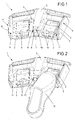
- 1 denotes a total of a foot switch having two actuators 2 in the form of buttons or switches.
- the actuators 2 are movably mounted about a pivot axis 3 and operable with the foot when the foot switch 1 rests on a substrate such as the floor of an operating room o.
- the actuators 2 are each surrounded by blocking elements 4, which are formed by a housing 5 of the foot holder 1.
- the blocking elements 4 are designed as two raised, lateral ribs 6 and as a central separating web 7, wherein the separating web 7 by an attachment 8 has an additionally increased height.
- detection areas 9 of proximity sensors 10 and 11 are provided.
- Each two 10 are arranged in the essay 8 as well in each case a proximity sensor 11 in a rib 6, wherein the proximity sensors are each configured as a light barrier and are arranged in pairs in the manner of a light barrier transmitted light variant.
- the proximity sensors 10 and 11 radiate through the respective detection area 9 and thus ensure, via the respective actuating member 2, the approach corridor above the respective actuating member 2.
- the proximity sensors 10 in the attachment 8 in each case radiate through the detection region 9 of a complete approach corridor, that is over the entire width of an actuator 2, up to a reflector arranged opposite in a rib 6, which is in this Case would be marked with 11.
- the reflector 11 in this embodiment reflects the light to the proximity sensor 10.
- the proximity sensor 10 in this embodiment thus comprises both light-emitting and light-receiving elements, so that a simplified cable management is possible, which leads into the attachment 8 of the divider 7 and there two proximity sensors 10.
- the proximity sensors 10 and 11 are arranged in the housing 5 of the foot switch 1. Deviating from this, differently configured proximity sensors can also be used or the proximity sensors can be arranged elsewhere.
- a proximity sensor can be realized, for example in the form of a capacitive sensor, so that when approaching a foot to the actuator 2, this proximity sensor is activated.
- Fig. 2 shows the footswitch 1 of Fig. 1 , wherein a shoe 12 is located in the detection area 9 of the right-hand actuator 2, even before the shoe 12 touches the actuator 2.
- a provided in the footswitch 1 or the footswitch 1 associated electronic circuit is operatively connected to the proximity sensors 10 and 11 of this right actuator 2 and activates a signal generator when the proximity sensor 10 and 11 detects the presence of the shoe 12.
- the subsequently generated signal differs from a signal which is emitted when the shoe 12 comes into the detection area 9 of the left actuator 2, so that the user receives an indication of which function by the respective signaling before actuation of the respective actuator 2 a connected to the footswitch 1 device he will soon trigger.
Landscapes
- Engineering & Computer Science (AREA)
- General Engineering & Computer Science (AREA)
- Theoretical Computer Science (AREA)
- Human Computer Interaction (AREA)
- Physics & Mathematics (AREA)
- General Physics & Mathematics (AREA)
- Push-Button Switches (AREA)
- Switches Operated By Changes In Physical Conditions (AREA)
Abstract
Description
Die Erfindung betrifft einen Fußschalter nach dem Oberbegriff des Anspruchs 1.The invention relates to a foot switch according to the preamble of
Gattungsgemäße Fußschalter sind aus der Medizintechnik bekannt. Sie werden dort eingesetzt, um Geräte, wie beispielsweise Hochfrequenz-Chirurgiegeräte, Patientenliegen, Röntgengeräte, Lasergeräte u. dgl., zu steuern. Da der Arzt bei seiner Arbeit am Patienten die Hände nicht frei hat, steuert er die medizinischen Geräte mit Hilfe der Fußschalter. Dies hat weiterhin den Vorteil, dass die Hände des Arztes steril bleiben und er lediglich mit den Füßen die ggf. unsterilen Fußschalter berührt.Generic footswitches are known from medical technology. They are used there to devices such as high-frequency surgical equipment, patient beds, X-ray machines, laser devices and. Like., To control. Since the doctor does not have his hands free while working on the patient, he controls the medical devices with the help of the foot switches. This has the further advantage that the doctor's hands remain sterile and he touches only with the feet of possibly unsterile footswitch.
In der Praxis steht der Arzt häufig vor dem Problem, mit Hilfe von mehreren Fußschaltern mehrere medizinische Geräte steuern zu müssen. Insbesondere wenn die Arbeit am Patienten ein so hohes Maß an Konzentration vom Arzt verlangt, dass dieser den Blick nicht vom Patienten abwenden kann, ist er zur Ansteuerung der medizinischen Geräte ausschließlich auf die taktilen Reize angewiesen, wenn er nach unterschiedlichen Fußschaltern zum Ansteuern der jeweils unterschiedlichen medizinischen Geräte tastet. Fehlbedienungen, beispielsweise das nicht rechtzeitige Einschalten des gewünschten medizinischen Gerätes oder das versehentliche Einschalten eines zu dem Zeitpunkt nicht erwünschten medizinischen Gerätes können Gefahren für den Patienten und/oder für den Arzt und ggf. anwesende Arzthelfer bedeuten.In practice, the doctor often faces the problem of having to control several medical devices with the help of several foot switches. In particular, when the work on the patient requires such a high degree of concentration from the doctor that he can not avert the gaze from the patient, he is only required to control the medical devices on the tactile stimuli, if he used different foot switches for driving the respectively different touches medical devices. Operating errors, such as not turning on the desired medical device in time or accidentally switching on a medical device that is not wanted at the time can be dangerous for the patient Patients and / or for the doctor and possibly present medical assistants.
Der Erfindung liegt die Aufgabe zugrunde, einen gattungsgemäßen Fußschalter dahingehend zu verbessern, dass dieser auch ohne Blickkontakt zum Fußschalter eine eindeutige Identifizierung des jeweiligen Fußschalters vor dessen Betätigung ermöglicht.The invention has for its object to improve a generic footswitch to the effect that this allows a clear identification of the respective footswitch before its operation without eye contact with the footswitch.
Diese Aufgabe wird durch einen Fußschalter mit den Merkmalen des Anspruchs 1 gelöst.This object is achieved by a foot switch with the features of
Die Erfindung schlägt mit anderen Worten vor, dem Betätigungsorgan des Fußschalters einen Annäherungssensor vorzuschalten, so dass die Anwesenheit des Fußes detektiert wird, bevor die eigentliche Aktion ausgelöst werden kann, die bei Betätigung des Betätigungsorgans vorgesehen ist, beispielsweise die Ansteuerung des an diesen Fußschalter angeschlossenen medizinischen Gerätes. Dabei ist es unerheblich, ob das Betätigungsorgan eine analoge oder digitale Funktion hat. Der Fußschalter weist eine elektronische Schaltung auf, die mit dem Annäherungssensor wirksam verbunden ist und die einen Signalausgang aufweist. Wenn sensorisch die Annäherung des Fußes an das Betätigungsorgan detektiert wird, so wird mittels der elektronischen Schaltung der Signalausgang automatisch angesteuert.In other words, the invention proposes to connect a proximity sensor to the actuating member of the foot switch, so that the presence of the foot is detected before the actual action can be triggered, which is provided upon actuation of the actuator, for example the control of the medical connected to this foot switch device. It is irrelevant whether the actuator has an analog or digital function. The footswitch has an electronic circuit operatively connected to the proximity sensor and having a signal output. If the sensory approach of the foot to the actuator is detected, the signal output is automatically controlled by means of the electronic circuit.
Ein an diesen Signalausgang angeschlossener Signalgeber gibt daraufhin ein optisches und/oder akustisches Signal ab. Auf diese Weise kann anhand des Signals erkannt werden, dass dieser Fußschalter betätigt wird, und dass eine weitere Bewegung des Fußes zur Aktivierung des Betätigungsorgans führen wird. Wenn mehrere Fußschalter vorschlagsgemäß ausgestaltet sind und sich ihre Signale voneinander unterscheiden, kann allein anhand dieser Signalisierung bereits vor Betätigung des jeweiligen Betätigungsorgans der Arzt darauf aufmerksam gemacht werden, welchen Fußschalter er momentan bedient und welches medizinische Gerät bei weiterer Betätigung des Fußschalters und bei Betätigung des Betätigungsorgans angesteuert werden wird. Auf diese Weise wird der Anwender vor einer Fehlbedienung des Fußschalters und vor einer versehentlichen Fehlbedienung eines medizinischen Gerätes gewarnt.A signal generator connected to this signal output then emits an optical and / or acoustic signal. In this way, it can be seen from the signal that this foot switch is actuated, and that further movement of the foot will result in activation of the actuator. If several footswitches are designed according to the proposal and their signals differ from each other, the physician can be made aware of this already on the basis of this signaling before actuation of the respective actuating member, which footswitch he currently operates and which medical device will be controlled upon further actuation of the footswitch and upon actuation of the actuator. In this way, the user is warned against incorrect operation of the footswitch and accidental misuse of a medical device.
Der Annäherungssensor kann beispielsweise als Drahtbügel o. dgl. ausgestaltet sein, der federbelastet und beweglich ist, so dass durch Kontakt mit einem derartigen Bügel die Signalisierung ausgelöst werden kann. Vorteilhaft kann allerdings vorgesehen sein, dass der Annäherungssensor als berührungsloser Sensor ausgestaltet ist, so dass die Betätigung des eigentlichen Betätigungsorgans für den Anwender, der bereits an bestimmte Fußschalter gewöhnt ist, unverändert bleiben kann und keine zusätzlichen taktilen Reize, mechanischen Widerstände o. dgl. zu überwinden sind.The proximity sensor can be designed, for example, as a wire bow or the like, which is spring-loaded and movable, so that the signaling can be triggered by contact with such a bracket. Advantageously, however, be provided that the proximity sensor is designed as a non-contact sensor, so that the operation of the actual actuator for the user who is already used to certain footswitch, can remain unchanged and no additional tactile stimuli, mechanical resistances o. The like overcome.
So kann beispielsweise der Annäherungssensor als Lichtschranke ausgestaltet sein, als kapazitiver, Infrarot- oder Ultraschallsensor, so dass jeweils auch glattflächige Oberflächen des Fußschalters ermöglicht werden, die eine einfache und zuverlässige Reinigung des Fußschalters gestatten.Thus, for example, the proximity sensor can be configured as a light barrier, as a capacitive, infrared or ultrasonic sensor, so that in each case smooth surfaces of the foot switch are made possible, allowing a simple and reliable cleaning of the footswitch.
Vorteilhaft kann der Signalgeber innerhalb des Fußschalters selbst angeordnet sein und ein akustisches Signal abgeben. Auf diese Weise ist die Signalisierung auch dann sichergestellt, wenn der Anwender nicht auf ein Display o. dgl., und insbesondere nicht auf den Fußschalter selbst während seiner Tätigkeit blicken möchte.Advantageously, the signal generator can be arranged within the foot switch itself and emit an acoustic signal. In this way, the signaling is ensured even if the user does not want to look at a display o. The like., And in particular not on the footswitch itself during his job.
Alternativ dazu kann vorgesehen sein, dass der Signalgeber außerhalb des Fußschalters angeordnet ist und mit dem Signalausgang des Fußschalters übertragungswirksam verbunden werden kann. So kann beispielsweise ein an einem medizinischen Gerät ohnehin vorgesehener Monitor eine Warnleuchte o. dgl. als Signalgeber genutzt werden oder es kann eigens ein Bildschirm vorgesehen sein, an dem mehrere vorschlagsgemäß ausgestaltete Fußschalter angeschlossen sind, so dass auf diesem Bildschirm angezeigt werden kann, welcher Fußschalter jeweils betätigt wird oder kurz vor seiner Betätigung steht, an welchem Fußschalter also der Annäherungssensor die Anwesenheit eines Fußes detektiert hat.Alternatively, it can be provided that the signal generator is arranged outside the footswitch and can be connected to the signal output of the footswitch transfer-effective. Thus, for example, a monitor provided on a medical device anyway may have a warning light o. Like. Be used as a signal generator or it may be specifically provided a screen to which a plurality of footswitch designed according to are connected, so that can be displayed on this screen, which footswitch is pressed or shortly before its operation, which footswitch so the Proximity sensor has detected the presence of a foot.
Vorteilhaft können bei komplexer aufgebauten Fußschaltern, die mehrere Betätigungsorgane aufweisen, auch mehrere Annäherungssensoren vorgesehen sein, so dass zumindest Betätigungsorgane, die ähnlich aufgebaut sind und daher ähnlich zu betätigen sind und ähnlich taktile Reize dem Anwender vermitteln, voneinander unterschieden werden können. Dementsprechend sind mehreren Betätigungsorganen eines solchen Fußschalters jeweils ein eigener Annäherungssensor zugeordnet sowie eine elektronische Schaltung, welche die Signale der Annäherungssensoren auswertet und ein Signalgeber, der entweder je nach aktiviertem Sensor unterschiedliche Signale ausgibt, oder wobei jedem überwachten Betätigungsorgan ein eigener, unterschiedlich von anderen ausgestalteter Signalgeber zugeordnet ist.In the case of complex foot switches which have a plurality of actuators, it is also advantageous to provide a plurality of proximity sensors, so that at least actuators which are of similar construction and therefore can be actuated similarly and impart similar tactile stimuli to the user can be differentiated from one another. Accordingly, a plurality of actuators of such a footswitch are each assigned a separate proximity sensor and an electronic circuit which evaluates the signals of the proximity sensors and a signal generator that either outputs different signals depending on the activated sensor, or each monitored actuator a separate, differently designed by other signal generator assigned.
Im einfachsten Fall jedoch, wenn sämtlichen Betätigungsorganen desselben Fußchalters stets dasselbe Signal zugeordnet ist, wird zumindest zuverlässig die Betätigung jedes Betätigungsorgans dieses Fußschalters durch die Annäherungssensoren überwacht, so dass dann eine Signalisierung erfolgen kann, die für sämtliche Betätigungsorgane dieses Fußschalters gleich ist und eine Unterscheidung von einer Betätigung eines anderen Fußschalters ermöglicht. Die Unterscheidung der einzelnen Betätigungsorgane innerhalb desselben Fußschalters kann dann in an sich bekannter Weise durch unterschiedliche Ausgestaltung der einzelnen Betätigungsorgane oder durch unterschiedliche Ausgestaltung des Gehäuses in der Umgebung der einzelnen Betätigungsorgane erfolgen, so dass die schon erwähnten taktilen Reize für die unterschiedlichen Betätigungsorgane desselben Fußschalters unterschiedlich sind und dem Anwender die erforderliche Unterscheidung ermöglichen.In the simplest case, however, if all the actuators of the same footswitch is always assigned the same signal, the actuation of each actuator of this footswitch is at least reliably monitored by the proximity sensors, so that then a signaling can be made, which is the same for all actuators of this footswitch and a distinction an actuation of another foot switch allows. The distinction of the individual actuators within the same footswitch can then be done in a conventional manner by different design of the individual actuators or by different design of the housing in the environment of the individual actuators, so that the already mentioned tactile Stimuli for the different actuators of the same footswitch are different and allow the user the required distinction.
Vorteilhaft kann das Betätigungsorgan von so genannten Sperrelementen umgeben sein, so dass das Betätigungsorgan nicht aus beliebigen Richtungen zugänglich ist. Auf diese Weise ergibt sich ein regelrechter Annäherungskorridor für die Betätigung des Betätigungsorgans, so dass auf diese Weise besonders zuverlässig die Überwachung des Betätigungsorgans mit Hilfe des Annäherungssensors erfolgen kann, indem dieser seinen Erfassungsbereich innerhalb des Annäherungskorridors hat.Advantageously, the actuator may be surrounded by so-called locking elements, so that the actuator is not accessible from any direction. In this way, there is a veritable approach corridor for the actuation of the actuator, so that in this way the monitoring of the actuator with the aid of the proximity sensor can be carried out particularly reliably by having its detection range within the approaching corridor.
Vorteilhaft kann eine besonders preisgünstige Ausgestaltung des Fußschalters dadurch erfolgen, dass das Gehäuse keine zusätzlichen Elemente, wie Sperrelemente oder Halterungen für die Annäherungssensoren o. dgl. benötigt, indem vielmehr das Betätigungsorgan selbst weiterentwickelt wird und derart ausgestaltet ist, dass es vor der Ansteuerung des angeschlossenen medizinischen Gerätes zunächst einen so genannten Leerweg aufweist, also einen Betätigungsweg, der noch nicht zum Ansteuern des angeschlossenen medizinischen Gerätes führt, sondern der als Bewegung des Betätigungsorgans sensorisch erfasst wird, so dass in diesem Bereich des Leerwegs der Annäherungssensor verwirklicht ist, der zu der entsprechenden Signalisierung führt.Advantageously, a particularly inexpensive design of the footswitch can be done in that the housing no additional elements, such as locking elements or brackets for the proximity sensors o. The like. Required by rather the actuator itself is further developed and is designed such that it is before driving the connected medical device first comprises a so-called free travel, ie an actuation path that does not lead to the driving of the connected medical device, but is sensed as a movement of the actuator, so that in this area of the idle the proximity sensor is realized, which is the corresponding Signaling leads.
Vorteilhaft können bei Ansteuerung mehrerer medizinischer Geräte mehrere vorschlagsgemäße Fußschalter vorgesehen sein, wobei diese Anordnung von mehreren Fußschaltern eine klare Identifizierung der unterschiedlichen medizinischen Geräte dadurch ermöglicht, dass jedem dieser Fußschalter ein unterschiedliches Signal zugeordnet ist.Advantageously, a plurality of proposed footswitches can be provided for controlling a plurality of medical devices, this arrangement of a plurality of foot switches permitting a clear identification of the different medical devices in that each of these footswitches is assigned a different signal.
Vorteilhaft kann die Art des Signals am Fußschalter selbst eingestellt werden, indem die elektronische Schaltung bzw. der Signalgeber dementsprechend einstellbar ist. Die Art des Signals kann aus mehreren unterschiedlichen Signalarten ausgewählt werden, beispielsweise bei akustischen Signalen in Form unterschiedlicher Tonhöhen oder unterschiedlicher Tonfolgen.Advantageously, the type of signal on the footswitch itself can be adjusted by the electronic circuit or the signal generator is accordingly adjustable. The type of signal can be selected from several different signal types, for example, acoustic signals in the form of different pitches or different tone sequences.
Ein Ausführungsbeispiel der Erfindung wird anhand der rein schematischen Darstellungen näher erläutert. Dabei zeigt
- Fig. 1
- eine perspektivische Ansicht von oben auf einen Fußschalter, und
- Fig. 2
- eine Ansicht wie in
Fig. 1 , wobei zur Betätigung eines Betätigungsorgans der Fuß eines Anwenders durch einen schematisch angedeuteten Schuh symbolisiert ist.
- Fig. 1
- a perspective view from above of a foot switch, and
- Fig. 2
- a view like in
Fig. 1 , wherein for actuating an actuator, the foot of a user is symbolized by a schematically indicated shoe.
In den Zeichnungen ist mit 1 insgesamt ein Fußschalter bezeichnet, der zwei Betätigungsorgane 2 in Form von Tastern bzw. Schaltern aufweist. Die Betätigungsorgane 2 sind um jeweils eine Schwenkachse 3 beweglich gelagert und mit dem Fuß betätigbar, wenn der Fußschalter 1 auf einem Untergrund wie dem Boden eines Operationssaals o. dgl. aufliegt.In the drawings, 1 denotes a total of a foot switch having two
Die Betätigungsorgane 2 sind jeweils von Sperrelementen 4 umgeben, die von einem Gehäuse 5 des Fußhalters 1 gebildet werden. Die Sperrelemente 4 sind als zwei erhöhte, seitliche Rippen 6 und als ein mittlerer Trennsteg 7 ausgestaltet, wobei der Trennsteg 7 durch einen Aufsatz 8 eine zusätzlich vergrößerte Höhe aufweist. Mit Hilfe der Sperrelemente 4 ist verhindert, dass sich der Fuß des Anwenders den Betätigungsorganen 2 von der Seite her nähern kann. Vielmehr muss sich der Fuß des Anwenders jeweils von vorn bzw. von oben, also innerhalb eines durch die Sperrelemente 4 vorgegebenen Annäherungskorridors, dem jeweiligen Betätigungsorgan 2 nähern.The
Innerhalb jedes dieser vorgegebenen Annäherungskorridore sind Erfassungsbereiche 9 von Annäherungssensoren 10 und 11 vorgesehen. Jeweils zwei 10 sind im Aufsatz 8 angeordnet sowie jeweils ein Annäherungssensor 11 in einer Rippe 6, wobei die Annäherungssensoren jeweils als Lichtschranke ausgestaltet und jeweils paarweise in Art einer Lichtschranken-Durchlichtvariante angeordnet sind. Die Annäherungssensoren 10 und 11 strahlen dabei durch den jeweiligen Erfassungsbereich 9 und sichern somit, über das jeweilige Betätigungsorgan 2 hinweg, den Annäherungskorridor oberhalb des jeweiligen Betätigungsorgans 2.Within each of these predetermined approach corridors,
Abweichend von diesem Ausführungsbeispiel kann vorgesehen sein, dass die Annäherungssensoren 10 im Aufsatz 8 jeweils durch den Erfassungsbereich 9 eines kompletten Annäherungskorridors strahlen, also über die gesamte Breite eines Betätigungsorgans 2, und zwar bis zu einem gegenüberliegend in einer Rippe 6 angeordneten Reflektor, der in diesem Fall mit 11 gekennzeichnet wäre. Der Reflektor 11 reflektiert bei diesem Ausführungsbeispiel das Licht zum Annäherungssensor 10. Der Annäherungssensor 10 umfasst bei dieser Ausgestaltung also sowohl Licht aussendende als auch Licht empfangende Elemente, so dass eine vereinfachte Kabelführung ermöglicht ist, die in den Aufsatz 8 des Trennstegs 7 führt und dort zu beiden Annäherungssensoren 10.Notwithstanding this embodiment, it can be provided that the
Bei dem dargestellten Ausführungsbeispiel sind die Annäherungssensoren 10 und 11 im Gehäuse 5 des Fußschalters 1 angeordnet. Abweichend davon können auch anders ausgestaltete Annäherungssensoren Anwendung finden bzw. die Annäherungssensoren an anderer Stelle angeordnet sein. Beispielsweise kann im Betätigungsorgan 2 selbst ein Annäherungssensor verwirklicht sein, beispielsweise in Form eines kapazitiven Sensors, so dass bei Annäherung eines Fußes an das Betätigungsorgan 2 dieser Annäherungssensor aktiviert wird.In the illustrated embodiment, the
Claims (15)
gekennzeichnet durch
einen Annäherungssensor (10), welcher den Raum vor dem Betätigungsorgan (2) erfassend angeordnet ist, und eine elektronische Schaltung, die einen Signalausgang aufweist und derart ausgestaltet ist, dass sie bei sensorisch detektierter Annäherung eines Fußes an das Betätigungsorgan (2) den Signalausgang ansteuert, derart, dass ein an diesen Signalausgang angeschlossener Signalgeber ein optisches und / oder akustisches Signal abgibt.Foot switch, with a housing and with at least one actuatable by foot, designed as a switch or button actuator,
marked by
a proximity sensor (10), which is arranged to detect the space in front of the actuator (2), and an electronic circuit which has a signal output and is designed such that it controls the signal output at sensory detected approach of a foot to the actuator (2) in such a way that a signal transmitter connected to this signal output emits an optical and / or acoustic signal.
dadurch gekennzeichnet,
dass der Annäherungssensor (10) als berührungsloser Sensor ausgestaltet ist.Footswatter according to claim 1,
characterized,
that the proximity sensor (10) is designed as a contactless sensor.
dadurch gekennzeichnet,
dass der Annäherungssensor (10) als Lichtschranke ausgestaltet ist.Footswitch according to claim 2,
characterized,
that the proximity sensor (10) is designed as a light barrier.
dadurch gekennzeichnet,
dass der Annäherungssensor (10) als kapazitiver Sensor ausgestaltet ist.Footswitch according to claim 2,
characterized,
that the proximity sensor (10) is designed as a capacitive sensor.
dadurch gekennzeichnet,
dass der Annäherungssensor (10) als Ultraschallsensor ausgestaltet ist.Footswitch according to claim 2,
characterized,
that the proximity sensor (10) is designed as an ultrasonic sensor.
dadurch gekennzeichnet,
dass der Annäherungssensor (10) als Infrarotsensor ausgestaltet ist.Footswitch according to claim 2,
characterized,
that the proximity sensor (10) is designed as an infrared sensor.
dadurch gekennzeichnet,
dass der Signalgeber innerhalb des Fußschalters (1) angeordnet und ein akustisches Signal abgebend ausgestaltet ist.Footswitch according to one of the preceding claims,
characterized,
in that the signal transmitter is arranged within the foot switch (1) and is designed to emit an acoustic signal.
dadurch gekennzeichnet,
dass der Signalgeber außerhalb des Fußschalters (1) angeordnet und mit dem Signalausgang übertragungswirksam verbindbar ist.Footswitch according to one of claims 1 to 6,
characterized,
in that the signal transmitter is arranged outside the footswitch (1) and can be connected to the signal output in a transfer-effective manner.
dadurch gekennzeichnet,
dass der Signalausgang des Fußschalters (1) an ein medizinisches Anzeigegerät angepasst ist, welches einen Signalgeber aufweist, derart, dass der Signalgeber des an den Signalausgang des Fußschalters (1) angeschlossenen medizinischen Anzeigegeräts das optische und / oder akustische Signal abgibt.Footswitch according to claim 7,
characterized,
in that the signal output of the foot switch (1) is adapted to a medical display device which has a signal generator such that the signal generator of the medical display device connected to the signal output of the foot switch (1) emits the optical and / or acoustic signal.
gekennzeichnet durch
mehrere Betätigungsorgane (2), wobei den Betätigungsorganen (2) jeweils ein Annäherungssensor (10), eine elektronische Schaltung und ein Signalgeber zugeordnet ist.Footswitch according to one of the preceding claims,
marked by
a plurality of actuators (2), wherein the actuators (2) each associated with a proximity sensor (10), an electronic circuit and a signal generator.
dadurch gekennzeichnet,
dass jedem der mehreren Betätigungsorgane (2) ein unterschiedliches Signal zugeordnet ist.Footswitch according to claim 9,
characterized,
that each of the plurality of actuators (2) has a different Signal is assigned.
dadurch gekennzeichnet,
dass das Betätigungsorgan (2) von Sperrelementen (4) umgeben ist, derart, dass der Zugang zu dem Betätigungsorgan (2) nur innerhalb eines von den Sperrelementen (4) freien Annäherungskorridors ermöglicht ist.Footswitch according to one of the preceding claims,
characterized,
in that the actuating member (2) is surrounded by blocking elements (4), such that access to the actuating member (2) is only possible within an approaching corridor free of the blocking elements (4).
dadurch gekennzeichnet,
dass der Annäherungssensor (10) innerhalb des Betätigungsorgans (2) vorgesehen ist, derart, dass das Betätigungsorgan (2) zunächst einen als Leerweg bezeichneten Betätigungsweg aufweist, der zur Aktivierung des Annäherungssensors (10) dient.Footswitch according to one of the preceding claims,
characterized,
in that the proximity sensor (10) is provided inside the actuating member (2), such that the actuating member (2) initially has an actuating travel, referred to as free travel, which activates the proximity sensor (10).
dadurch gekennzeichnet,
dass die elektronische Schaltung und / oder der Signalgeber einstellbar ist, derart, dass die Art des Signals aus mehreren unterschiedlichen Signalarten wählbar ist.Footswitch according to one of the preceding claims,
characterized,
that the electronic circuit and / or the signal generator is adjustable, such that the type of signal can be selected from a plurality of different signal types.
Applications Claiming Priority (2)
| Application Number | Priority Date | Filing Date | Title |
|---|---|---|---|
| DE202010015472 | 2010-11-17 | ||
| DE202011000441U DE202011000441U1 (en) | 2010-11-17 | 2011-02-25 | Footswitch with foot detection |
Publications (2)
| Publication Number | Publication Date |
|---|---|
| EP2456072A2 true EP2456072A2 (en) | 2012-05-23 |
| EP2456072A3 EP2456072A3 (en) | 2012-12-12 |
Family
ID=43993278
Family Applications (1)
| Application Number | Title | Priority Date | Filing Date |
|---|---|---|---|
| EP11188366A Withdrawn EP2456072A3 (en) | 2010-11-17 | 2011-11-09 | Foot switch with foot detection |
Country Status (2)
| Country | Link |
|---|---|
| EP (1) | EP2456072A3 (en) |
| DE (1) | DE202011000441U1 (en) |
Families Citing this family (2)
| Publication number | Priority date | Publication date | Assignee | Title |
|---|---|---|---|---|
| DE102011082607B4 (en) * | 2011-09-13 | 2017-08-03 | Siemens Healthcare Gmbh | Recording device for a wireless operable electronic device, in particular a flat detector of an X-ray device, and mobile X-ray device |
| DE102018106737A1 (en) * | 2018-03-21 | 2019-09-26 | Olympus Winter & Ibe Gmbh | An electrosurgical system |
Family Cites Families (3)
| Publication number | Priority date | Publication date | Assignee | Title |
|---|---|---|---|---|
| US5422521A (en) * | 1993-11-18 | 1995-06-06 | Liebel-Flarsheim Co. | Foot operated control system for a multi-function device |
| DE102005043047B4 (en) * | 2005-09-09 | 2009-02-12 | Siemens Ag | Device with operating switch |
| DE202008013551U1 (en) * | 2008-10-15 | 2009-01-22 | steute Schaltgeräte GmbH & Co. KG | Multifunction footswitch |
-
2011
- 2011-02-25 DE DE202011000441U patent/DE202011000441U1/en not_active Expired - Lifetime
- 2011-11-09 EP EP11188366A patent/EP2456072A3/en not_active Withdrawn
Non-Patent Citations (1)
| Title |
|---|
| None |
Also Published As
| Publication number | Publication date |
|---|---|
| DE202011000441U1 (en) | 2011-05-12 |
| EP2456072A3 (en) | 2012-12-12 |
Similar Documents
| Publication | Publication Date | Title |
|---|---|---|
| EP1419432B1 (en) | Device for operating a medical appliance, especially a mobile operating table | |
| EP2455959B1 (en) | Switching device for a medical appliance and method for operating switching device | |
| EP2497868B1 (en) | Device for triggering the electrical release of water | |
| DE102005028215A1 (en) | X-ray system used for treatment of patient, has guidance device that includes user-operated joystick which exerts vibratory warning force, that can be perceived in tactile manner by user, based on warning signal from monitoring device | |
| DE102014014498B4 (en) | Device equipped with a touchscreen and method for controlling such a device | |
| DE102012205549A1 (en) | Method for operating e.g. deadman switch in contactless controlled medical device e.g. C-arm x-ray device, involves detecting response signal by part of user, and operating switch depending on detected response signal | |
| DE102006057682A1 (en) | Switching device for medical or surgical devices | |
| CH700524B1 (en) | Household unit with touchless gesture operation. | |
| DE202008013551U1 (en) | Multifunction footswitch | |
| EP4014103A1 (en) | Interface for a medical device with an adaptive actuation sensor | |
| EP3270309B1 (en) | Display device for a medical device | |
| EP2456072A2 (en) | Foot switch with foot detection | |
| EP1090602A1 (en) | Dental device | |
| WO2018114432A1 (en) | Operator control apparatus, which can be operated in a contact-free manner, for a motor vehicle, and also motor vehicle and operating method for the operator control apparatus | |
| DE102013104429A1 (en) | Medical device has control or regulating device that controls function of the medical device based on detection of control or rule command according to gesture or facial expression of surgeon | |
| DE10332708B3 (en) | Contactless setting of water quantity and temperature from sanitary appliance, has array of closely-arranged sensors, with averaging circuit which outputs average of set-points | |
| DE4125313A1 (en) | METHOD FOR CONTROLLING A DENTAL TREATMENT DEVICE AND A DENTAL TREATMENT DEVICE | |
| EP2754404A1 (en) | Ophthalmic surgery device | |
| WO2020233750A1 (en) | Operating device for a table, and table comprising same | |
| DE102010021885A1 (en) | Dental treatment device, has medical glass operating unit comprising electronic system, and display arranged in area of glass plate for displaying error that occurs during contact of electrical devices with external influences | |
| DE102015204767A1 (en) | Operation of a medical device | |
| DE102015005398A1 (en) | operating terminal | |
| DE102014202433B4 (en) | Cover unit for a device unit | |
| WO2007134738A1 (en) | Arrangement for influencing device functions by means of a foot movement | |
| WO2003044287A2 (en) | Arrangement for the manual non-contact operation of an electrical device |
Legal Events
| Date | Code | Title | Description |
|---|---|---|---|
| PUAI | Public reference made under article 153(3) epc to a published international application that has entered the european phase |
Free format text: ORIGINAL CODE: 0009012 |
|
| AK | Designated contracting states |
Kind code of ref document: A2 Designated state(s): AL AT BE BG CH CY CZ DE DK EE ES FI FR GB GR HR HU IE IS IT LI LT LU LV MC MK MT NL NO PL PT RO RS SE SI SK SM TR |
|
| AX | Request for extension of the european patent |
Extension state: BA ME |
|
| PUAL | Search report despatched |
Free format text: ORIGINAL CODE: 0009013 |
|
| AK | Designated contracting states |
Kind code of ref document: A3 Designated state(s): AL AT BE BG CH CY CZ DE DK EE ES FI FR GB GR HR HU IE IS IT LI LT LU LV MC MK MT NL NO PL PT RO RS SE SI SK SM TR |
|
| AX | Request for extension of the european patent |
Extension state: BA ME |
|
| RIC1 | Information provided on ipc code assigned before grant |
Ipc: H01H 3/14 20060101ALI20121105BHEP Ipc: H03K 17/945 20060101AFI20121105BHEP |
|
| STAA | Information on the status of an ep patent application or granted ep patent |
Free format text: STATUS: THE APPLICATION IS DEEMED TO BE WITHDRAWN |
|
| 18D | Application deemed to be withdrawn |
Effective date: 20130613 |