EP2455827A1 - Appareil de terrain avec un mode de basse consommation qui peut être activé et désactivé au travers des deux interfaces de l' appareil de terrain - Google Patents
Appareil de terrain avec un mode de basse consommation qui peut être activé et désactivé au travers des deux interfaces de l' appareil de terrain Download PDFInfo
- Publication number
- EP2455827A1 EP2455827A1 EP10191866A EP10191866A EP2455827A1 EP 2455827 A1 EP2455827 A1 EP 2455827A1 EP 10191866 A EP10191866 A EP 10191866A EP 10191866 A EP10191866 A EP 10191866A EP 2455827 A1 EP2455827 A1 EP 2455827A1
- Authority
- EP
- European Patent Office
- Prior art keywords
- switching device
- electrical switching
- energy
- saving mode
- input means
- Prior art date
- Legal status (The legal status is an assumption and is not a legal conclusion. Google has not performed a legal analysis and makes no representation as to the accuracy of the status listed.)
- Withdrawn
Links
Images
Classifications
-
- G—PHYSICS
- G05—CONTROLLING; REGULATING
- G05B—CONTROL OR REGULATING SYSTEMS IN GENERAL; FUNCTIONAL ELEMENTS OF SUCH SYSTEMS; MONITORING OR TESTING ARRANGEMENTS FOR SUCH SYSTEMS OR ELEMENTS
- G05B19/00—Programme-control systems
- G05B19/02—Programme-control systems electric
- G05B19/04—Programme control other than numerical control, i.e. in sequence controllers or logic controllers
- G05B19/042—Programme control other than numerical control, i.e. in sequence controllers or logic controllers using digital processors
-
- G—PHYSICS
- G05—CONTROLLING; REGULATING
- G05B—CONTROL OR REGULATING SYSTEMS IN GENERAL; FUNCTIONAL ELEMENTS OF SUCH SYSTEMS; MONITORING OR TESTING ARRANGEMENTS FOR SUCH SYSTEMS OR ELEMENTS
- G05B2219/00—Program-control systems
- G05B2219/20—Pc systems
- G05B2219/25—Pc structure of the system
- G05B2219/25289—Energy saving, brown out, standby, sleep, powerdown modus for microcomputer
-
- G—PHYSICS
- G05—CONTROLLING; REGULATING
- G05B—CONTROL OR REGULATING SYSTEMS IN GENERAL; FUNCTIONAL ELEMENTS OF SUCH SYSTEMS; MONITORING OR TESTING ARRANGEMENTS FOR SUCH SYSTEMS OR ELEMENTS
- G05B2219/00—Program-control systems
- G05B2219/30—Nc systems
- G05B2219/34—Director, elements to supervisory
- G05B2219/34306—Power down, energy saving
-
- Y—GENERAL TAGGING OF NEW TECHNOLOGICAL DEVELOPMENTS; GENERAL TAGGING OF CROSS-SECTIONAL TECHNOLOGIES SPANNING OVER SEVERAL SECTIONS OF THE IPC; TECHNICAL SUBJECTS COVERED BY FORMER USPC CROSS-REFERENCE ART COLLECTIONS [XRACs] AND DIGESTS
- Y02—TECHNOLOGIES OR APPLICATIONS FOR MITIGATION OR ADAPTATION AGAINST CLIMATE CHANGE
- Y02P—CLIMATE CHANGE MITIGATION TECHNOLOGIES IN THE PRODUCTION OR PROCESSING OF GOODS
- Y02P70/00—Climate change mitigation technologies in the production process for final industrial or consumer products
- Y02P70/10—Greenhouse gas [GHG] capture, material saving, heat recovery or other energy efficient measures, e.g. motor control, characterised by manufacturing processes, e.g. for rolling metal or metal working
Definitions
- the invention relates to an electrical switching device.
- the electrical switching device is used in particular within industrial automation technology and is used to control a consumer connected to it.
- a consumer is an engine.
- the electrical switching device may be, for example, a motor starter or engine control unit.
- the electrical switching device is usually connected to a higher-level control, so that the electrical switching device and ultimately the consumer can be controlled via the higher-level control.
- Such a connection between the electrical switching device and the controller may be, for example, a point-to-point connection (IO-Link) or a bus connection (PROFIBUS, PROFINET, ASI, etc.).
- the higher-level controller can communicate with the electrical switching device by means of PROFINET, so that the controller can control the switching device and, ultimately, the load connected to the electrical switching device via PROFINET.
- Such switching devices which are controlled via PROFINET, can also be compatible with PROFIenergy.
- PROFIenergy is a profile for energy management in production plants. PROFIenergy uses the PROFINET communication protocol. With PROFIenergy, the energy consumption of automation equipment in production (such as robot assembly cells, laser cutting systems and subsystems such as paint shops) can be controlled. The control of the energy consumption (eg of the electrical switching device itself) takes place via open and standardized commands, which are applied to planned and unplanned interruptions in production.
- Switching devices that are addressed via PROFIenergy commands can thus assume an operating mode and an energy-saving mode.
- the electrical switching device can be controlled by means of the bus system or a local local control ("manual control"). If the consumer is, for example, a motor, in particular the motor can be switched on and off.
- On-site local control takes place, for example, via buttons on the switching device or via a device connected to the switching device (for example, operator device, laptop, etc.).
- the switching device can thus be controlled centrally during the operating mode via the bus system or by means of the "manual control" on site.
- the electrical switching device can take energy-saving states.
- energy-saving measures can be initiated via standardized, manufacturer-independent commands. According to PROFIenergy, however, the energy-saving mode on the electrical switching device can only be activated and deactivated via the bus system.
- the energy-saving mode must be deactivated on the switchgear according to PROFIenergy via the bus system.
- Targeted maintenance, a local test operation or emergency running scenarios can thus not be carried out in plant sections which are in energy-saving mode and which comprise a plurality of electrical switching devices.
- a user wants to circumvent this problem he must specifically integrate measures in his plant control, which allow individual parts of the plant (eg an electrical switching device) to be released from the higher-level energy-saving mode. This has a number of disadvantages for the user: significant development and implementation costs, more complex dependencies and increased memory requirements for his user program.
- a device i. by an electric switching device, which comprises a first input means, for connecting a higher-level control, and a second input means, wherein the electrical switching device can assume an operating mode and a power-saving mode, wherein the energy-saving mode both via the first input means by the higher-level control and by means of second input means can be activated and deactivated.
- the electrical switching device is designed so that at least one component of the electrical switching device or the consumer connected to the electrical switching device is switched off in a transition from the operating mode to the energy-saving mode.
- the electrical switching device may preferably continue to receive and process control commands during the power saving mode via the first and second input means.
- the electrical switching device can take the operating mode and the energy-saving mode, the power consumption can be influenced by the switching device or the consumer. If, for example, the operating mode (working mode) for a foreseeable duration is not necessary for a consumer controlled by the electrical switching device, the energy-saving mode can be activated on the electrical switching device so that energy-saving measures can be initiated.
- the user can activate the energy-saving mode on the electrical switching device either by means of the first input device and thus via the higher-level control or by means of the second input device. Disabling energy-saving mode can also be done either by the first input means or the second input means.
- the activation and deactivation preferably takes place via a few input steps, in particular via only one input step. A manual, time-consuming switching of the electrical switching device can thus be omitted. This allows the energy-saving mode to be easily activated, even during short breaks, thus saving energy and operating costs.
- the second input means can thus be used to selectively activate or deactivate the energy-saving mode of an electrical switching device without having to use the higher-level control.
- the energy-saving mode can be selectively deactivated by means of the second input device only in the case of an electrical switching device locally without the remaining energy-saving mode switching devices having to deactivate the energy-saving mode. This represents a considerable improvement in terms of the operability and control of the electrical switching device.
- the higher-level controller is a master module and the first switching device is a slave.
- the first input means is a bus connection, so that the higher-level control, in particular a programmable logic controller, can be connected to the electrical switching device via a bus.
- the bus is in particular a fieldbus system such as PROFINET, PROFIBUS, ASI.
- the first input means can thus be connected to a bus system so that the electrical switching device can be controlled by means of the bus system.
- the energy-saving mode can be activated and deactivated via the bus system.
- the bus connection is a PROFINET bus connection and the energy-saving mode can be activated and deactivated by means of a PROFIenergy command.
- PROFIenergy is a manufacturer-independent communication protocol, via which in particular a respective energy-saving mode can be switched.
- the second input means comprises a control element, via which the energy-saving mode can be activated and deactivated.
- the operating element is preferably easily accessible to a user.
- the operating element can be, for example, an actuator (for example a button or rotary switch) or a touchscreen, via which the energy-saving mode can be easily activated or deactivated.
- the activation or deactivation can preferably take place by means of less than four input steps. In particular, a user can within max. Set the energy saving mode for 10 seconds.
- the second input means comprises an interface, to which a device can be connected, with which the energy-saving mode can be activated and deactivated.
- the device can be a sensor, an actuator and / or an operating device.
- the interface preferably comprises at least one digital input to which the sensor and / or actuator can be connected.
- the interface is preferably designed such that the handheld terminal and / or the laptop can be connected to the interface, so that it can be communicated with the electrical switching device.
- the laptop can be controlled in particular by means of an engineering tool (via software), the electrical switching device and in particular the energy-saving mode can be activated or deactivated.
- the interface enables communication with a mobile telecommunication means (eg mobile phone, smartphone, PDA), so that the energy-saving mode can be activated and deactivated via this.
- a mobile telecommunication means eg mobile phone, smartphone, PDA
- the energy-saving mode can be activated and deactivated via this.
- the device is a sensor and the second input means is a digital input, to which the sensor can be connected.
- the electrical switching device is designed so that at least one component of the electrical switching device or a consumer connected to the electrical switching device is switched off in a transition from the operating mode to the energy saving mode.
- the energy-saving mode is activated, energy-reducing measures are taken in comparison with the operating mode.
- the switching device is automatically set to the operating mode. During the energy saving mode, in particular, may continue between the parent Control and the electrical switching device are communicated.
- the energy-saving mode is preferably activated or deactivated by a single control command arriving via the first or second input means. There are preferably not several control commands required.
- the energy-saving mode (or a respective energy-saving variant) can preferably be selected directly on the part of the controller, the operating element and / or the device.
- the controller, the controls and / or the device or its program interface on a control panel which can selectively activate or deactivate the energy-saving mode or the individual energy-saving variants.
- the electrical switching device is an engine control unit or a motor starter.
- the consumer connected to the motor starter or engine control unit is in particular a motor.
- the energy-saving mode comprises at least two energy-saving variants, which can each be activated and deactivated by means of the first and second input means.
- first and second input means By means of the first and second input means thus different energy-saving variants can be controlled.
- an energy-saving variant can be selected specifically.
- the consumer connected to the electrical switching device is switched off and in a further energy-saving variant, additional components of the switching device are deactivated. In this way, a highly energy-efficient operation of a system comprising the electrical switching device, take place.
- the respective energy-saving variant specifies the duration in which the energy-saving mode should be active.
- the at least two energy-saving variants are implemented independently of communication in the switching device.
- first and second input means the same control steps within the switching device with respect to the respective energy-saving variant.
- the individual energy-saving variants can be controlled both via the first and the second input means and thus activated and deactivated.
- the electrical switching device comprises a processing unit, which is designed to process control commands of the first and second input means and to control the electrical switching device within the operating mode and the energy-saving mode.
- control commands issued by the processing unit for initiating a same power saving mode are the same control commands regardless of the source of the input (first or second input means).
- the energy-saving mode and in particular the respective energy-saving variant can thus be "selected" selectively via the first and second input means so that the energy-saving mode and in particular the selected energy-saving variant can be activated and deactivated by the processing unit.
- the processing unit is in particular a microprocessor.
- the processing unit is designed in such a way that, when the energy-saving mode is deactivated, the operating mode is automatically brought about.
- At least one measured value of the electrical switching device can be read out by means of the first and second input means.
- the measured value gives a physical quantity, which is measured by the electrical switching device can be, again.
- a measured value may be, for example, a current value, a voltage value, an apparent power, a reactive power, an active power, a phase shift or a maximum current.
- a control system which comprises an electrical switching device and a controller, wherein the controller is connected to the first input means and both the operating mode and the energy-saving mode can be activated and deactivated by means of the controller.
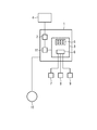
- FIG is a schematic representation of an electrical switching device.
- the figure shows a schematic representation of an electrical switching device 1.
- the electrical switching device 1 is in this case a motor starter, which is connected to a higher-level controller 4.
- the higher-level control can be, for example, a programmable logic controller (PLC).
- PLC programmable logic controller
- the electrical switching device 1 comprises a first input means 2.
- the communication with the higher-level controller 4 takes place in this embodiment by means of PROFINET.
- a PROFINET bus is connected to the electrical switching device 1, in particular to the first input means 2, and to the higher-level control 4 so that communication can take place via the PROFINET connection between the higher-level control 4 and the electrical switching device 1.
- the first input means 2 enables communication with the higher-level control 4 and thus control of the electrical switching device by means of a bus system.
- the electrical switching device 1 is further connected to a load 10, in particular a motor.
- the electrical switching device 1 can control this load 10.
- the higher-level controller 4 can also control the load 10 by means of the electrical switching device 1. For this purpose, commands are sent to the electrical switching device 1 via the present PROFINET connection.
- the electrical switching device 1 comprises, in addition to the first input means 2, a second input means 3 and a processing unit 11.
- the second input means 3 enables a local control of the switching device 1 on site.
- the second input device 3 comprises an operating element 5 and / or an interface 6.
- the switching device comprises both an operating element 5 and an interface 6.
- the operating element 5 which in this embodiment includes operating buttons
- the user 10 control directly from the electrical switching device 1.
- a user can also connect a device 7, 8, 9 to the interface 6 of the electrical switching device 1, so that a control of the electrical switching device 1 can take place locally by means of the connected device 7, 8, 9.
- the device 7, 8, 9 can be, for example, a handheld terminal 8, a laptop 9, a sensor 7, an actuator or a mobile telecommunication device.
- three devices 7, 8, 9 are connected to the interface 6.
- a sensor 7 is connected to the interface 6, preferably via digital inputs of the interface 6.
- a handheld terminal 8 and a laptop 9 is connected to the interface 6.
- the control of the electrical switching device by the laptop 9 is preferably carried out by means of an engineering tool.
- a user can thus locally control the electrical switching device 1 and, via it, the consumer 10.
- a targeted local control is thus possible.
- a control of the electrical switching device 1 can take place via the first and second input means 2, 3.
- the incoming signals via the first and second input means 2, 3 are evaluated by a processing unit 11, in particular a microcontroller.
- the processing unit 11 can then output corresponding control commands within the electrical switching device 1, so that there is a change in state within the electrical switching device 1 and / or the load 10.
- the electrical switching device 1 has, on the one hand, an operating mode and, on the other hand, an energy-saving mode.
- the operating mode represents the normal operation of the electrical switching device 1. During the operating mode, preferably all the functions of the electrical switching device 1 are available. Within the energy-saving mode, the electrical switching device 1 has an energetically improved state compared to the operating mode. During the energy-saving mode, for example, the load 10 connected to the electrical switching device 1 is deactivated and / or hardware components of the electrical switching device 1 are switched off. During the energy saving mode, however, there is no complete shutdown of the electrical switching device 1.
- the electrical switching device 1 is in a kind of stand-by operation, in which the electrical switching device 1 further commands, which via the first and second input means to the electrical switching device. 1 be sent registered.
- the electrical switching device 1 can be controlled both via the higher-level control 4 and via the hand control on site via the second input means 3. The electrical switching device 1 can thus activate or deactivate the energy-saving state as required via the first or second input means.
- a user is thus given the option of the energy-saving mode in addition to the use of the higher-level controller 4 (by means of the PROFINET communication with the PROFIenergy protocol frame and commands) as well as on the local control locally by means of the second input means 3 to make usable / accessible.
- the user has the option of establishing a local communication connection in addition to the bus communication via the interface 6 present on the motor starter.
- the local communication connection can be designed, for example, as a point-to-point connection. Via this local communication connection, e.g. the handheld terminal 8 or a PC engineering tool are connected, in which commands operating, monitoring, activation and deactivation of the energy-saving mode are integrated.
- the energy-saving mode in the electrical switching device 1 itself is implemented independently of communication, i. All energy saving functions integrated in the electrical switching device 1 always behave the same regardless of which communication channel (via the first or second input means 3, 4) the user operates the electrical switching device 1.
- the energy-saving mode can comprise different energy-saving variants, so that, for example, energy-saving measures are initiated depending on the foreseeable duration of the energy-saving mode.
- the user thus has the option of being able to activate / deactivate different energy-saving variants locally on the electrical switching device 1 and, on the other hand, to combine this local activation / deactivation with the activation / deactivation via the higher-level control 4.
- the user new usage scenarios are opened, which allow him in his plants (control systems, which include multiple electrical switching devices) standardized energy saving measures (eg PROFIenergy functionality) to perform flexibly over different communication channels.
- a user is enabled via the second input means 3 an equivalent communication with the switching device 1, as via the first input means 2.
- Measured values of the electrical switching device 1 can thus preferably also be evaluated via the second input means 3.
- the user is able to flexibly implement the energy-saving measures implemented in the switching device 1 (the different energy-saving variants) either via the higher-level control 4 (PROFINET communication) and / or the local communication (via the second input means 3) use and be able to use. That he can e.g. activate an energy-saving variant via the controller 4 and deactivate it locally again by means of the second input means 3 or vice versa.
- This combinability in accessing the energy saving measures integrated in the electrical switching device 1 opens up a series of new usage scenarios for the user.
- the electrical switching device 1 can also be used locally without communication connection via the first input means 2.
- a local commissioning and test of plant sub-areas can therefore already be carried out without a completed user program for the entire plant.
- the user can preferably supply the energy measured values of the PROFIenergy function supplied by the electrical switching device 1 not only via the higher-level control 4 but also locally to the switching device 1, e.g. read out by means of an engineering tool, observe and if necessary further process.
- Switchgear exchange with activated energy-saving mode Here is an example of a larger system with eg 150 electrical switching devices 1, which are each connected via the first input means 2 with a higher-level control 4 and controllable by means of a user program of the higher-level control 4. If the system with its 150 electrical switching devices 1 is in a power-saving mode which has been activated by means of the user program of the higher-level control 4, replacement of one of the electrical switching devices 1 of the system, eg due to a defect or maintenance, would inevitably lead to the new electrical switching device 1 (the new system participant) is no longer in energy-saving mode after the device replacement.
Priority Applications (1)
| Application Number | Priority Date | Filing Date | Title |
|---|---|---|---|
| EP10191866A EP2455827A1 (fr) | 2010-11-19 | 2010-11-19 | Appareil de terrain avec un mode de basse consommation qui peut être activé et désactivé au travers des deux interfaces de l' appareil de terrain |
Applications Claiming Priority (1)
| Application Number | Priority Date | Filing Date | Title |
|---|---|---|---|
| EP10191866A EP2455827A1 (fr) | 2010-11-19 | 2010-11-19 | Appareil de terrain avec un mode de basse consommation qui peut être activé et désactivé au travers des deux interfaces de l' appareil de terrain |
Publications (1)
| Publication Number | Publication Date |
|---|---|
| EP2455827A1 true EP2455827A1 (fr) | 2012-05-23 |
Family
ID=44146721
Family Applications (1)
| Application Number | Title | Priority Date | Filing Date |
|---|---|---|---|
| EP10191866A Withdrawn EP2455827A1 (fr) | 2010-11-19 | 2010-11-19 | Appareil de terrain avec un mode de basse consommation qui peut être activé et désactivé au travers des deux interfaces de l' appareil de terrain |
Country Status (1)
| Country | Link |
|---|---|
| EP (1) | EP2455827A1 (fr) |
Cited By (4)
| Publication number | Priority date | Publication date | Assignee | Title |
|---|---|---|---|---|
| DE102012211867B3 (de) * | 2012-07-06 | 2013-10-02 | Siemens Aktiengesellschaft | PROFIenergy in unterlagerten Kommunikationssystemen |
| EP2778811A1 (fr) * | 2013-03-15 | 2014-09-17 | Siemens Aktiengesellschaft | Dispositif pour un système d'interface AS |
| WO2015135577A1 (fr) * | 2014-03-12 | 2015-09-17 | Siemens Aktiengesellschaft | Dispositif pour faire fonctionner une installation d'automatisation avec une consommation d'énergie réduite |
| WO2016096334A1 (fr) * | 2014-12-16 | 2016-06-23 | Siemens Aktiengesellschaft | Dispositif pour la commande coordonnée d'un état de fonctionnement d'une installation de production ainsi que système de production et procédé |
Citations (3)
| Publication number | Priority date | Publication date | Assignee | Title |
|---|---|---|---|---|
| DE102007048476A1 (de) * | 2007-10-09 | 2009-04-16 | Endress + Hauser Process Solutions Ag | Energiesparender Betrieb einer drahtgebundenen Kommunikationsschnittstelle eines Feldgerätes |
| EP2202599A2 (fr) * | 2008-12-23 | 2010-06-30 | KUKA Roboter GmbH | Commande industrielle en réseau et procédé d'échange du mode de fonctionnement d'une telle commande industrielle |
| US20100198366A1 (en) * | 2009-02-05 | 2010-08-05 | Yokogawa Electric Corporation | Control device and control system |
-
2010
- 2010-11-19 EP EP10191866A patent/EP2455827A1/fr not_active Withdrawn
Patent Citations (3)
| Publication number | Priority date | Publication date | Assignee | Title |
|---|---|---|---|---|
| DE102007048476A1 (de) * | 2007-10-09 | 2009-04-16 | Endress + Hauser Process Solutions Ag | Energiesparender Betrieb einer drahtgebundenen Kommunikationsschnittstelle eines Feldgerätes |
| EP2202599A2 (fr) * | 2008-12-23 | 2010-06-30 | KUKA Roboter GmbH | Commande industrielle en réseau et procédé d'échange du mode de fonctionnement d'une telle commande industrielle |
| US20100198366A1 (en) * | 2009-02-05 | 2010-08-05 | Yokogawa Electric Corporation | Control device and control system |
Cited By (10)
| Publication number | Priority date | Publication date | Assignee | Title |
|---|---|---|---|---|
| DE102012211867B3 (de) * | 2012-07-06 | 2013-10-02 | Siemens Aktiengesellschaft | PROFIenergy in unterlagerten Kommunikationssystemen |
| KR20140005793A (ko) * | 2012-07-06 | 2014-01-15 | 지멘스 악티엔게젤샤프트 | 보조적 통신 시스템들에서의 profi에너지 |
| CN103532810A (zh) * | 2012-07-06 | 2014-01-22 | 西门子公司 | 下级的通讯系统中的PROFIenergy |
| CN103532810B (zh) * | 2012-07-06 | 2017-12-29 | 西门子公司 | 自动化系统和自动化系统的通讯方法 |
| EP2778811A1 (fr) * | 2013-03-15 | 2014-09-17 | Siemens Aktiengesellschaft | Dispositif pour un système d'interface AS |
| WO2015135577A1 (fr) * | 2014-03-12 | 2015-09-17 | Siemens Aktiengesellschaft | Dispositif pour faire fonctionner une installation d'automatisation avec une consommation d'énergie réduite |
| WO2016096334A1 (fr) * | 2014-12-16 | 2016-06-23 | Siemens Aktiengesellschaft | Dispositif pour la commande coordonnée d'un état de fonctionnement d'une installation de production ainsi que système de production et procédé |
| CN107003650A (zh) * | 2014-12-16 | 2017-08-01 | 西门子公司 | 用于协调地控制生产设施的运行状态的设备以及生产系统和方法 |
| CN107003650B (zh) * | 2014-12-16 | 2019-10-25 | 西门子公司 | 用于协调地控制生产设施的运行状态的设备以及生产系统和方法 |
| US10802454B2 (en) | 2014-12-16 | 2020-10-13 | Siemens Aktiengesellschaft | Device for coordinated controlling of an operating state of a production plant and production system and method |
Similar Documents
| Publication | Publication Date | Title |
|---|---|---|
| EP2806319B1 (fr) | Logiciel de configuration et procédé d'élaboration de données de configuration et d'un programme PLC pour un appareil de commande et/ou de protection comportant une commande de stockage programmable pour la technologie de moyenne ou haute tension | |
| EP2193411B1 (fr) | Procédé de fonctionnement d'un appareil de terrain dans un mode adapté en puissance | |
| EP2507888B1 (fr) | Procédé de réglage de paramètres d'un module d'alimentation en courant d'un appareil de terrain | |
| EP2098926B1 (fr) | Procédé et dispositif adaptés à la programmation et/ou la configuration d'un contrôleur de sécurité | |
| EP2098925A1 (fr) | Procédé et dispositif adaptés à la programmation et/ou la configuration d'un contrôleur de sécurité | |
| DE102010048810A1 (de) | System zur Bedienung mehrerer Plasma- und/oder Induktionserwärmungsprozesse | |
| EP2582090A1 (fr) | Procédé de configuration d'un dispositif de commande | |
| EP2016470B1 (fr) | Terminal de commande pour l'echange d'informations avec un appareil sur site dans un systeme d'automatisation | |
| EP2984530A1 (fr) | Appareil d'alimentation d'un transducteur de mesure, système destiné à être utilisé dans les techniques d'automatisation, et procédé d'utilisation dudit système | |
| WO2009060000A1 (fr) | Utilisation d'un adaptateur sans fil par le biais d'un appareil de terrain relié à celui-ci | |
| EP3629264A1 (fr) | Module de production | |
| DE102014001462B4 (de) | Feldbusmodul, Maschinensteuerung und Verfahren zur Parametrierung eines, insbesondere sicherheitsgerichteten, Feldbusmoduls | |
| EP3019920A1 (fr) | Unité de détection de données et système d'automatisation | |
| EP1840684A1 (fr) | Dispositif et système d'automatisation dont les composants peuvent communiquer par liaison radio utilisant des modules radio détachables | |
| EP2455827A1 (fr) | Appareil de terrain avec un mode de basse consommation qui peut être activé et désactivé au travers des deux interfaces de l' appareil de terrain | |
| DE102009047535B4 (de) | Verfahren zum Ermitteln einer Anschlusskonfiguration eines Feldgerätes an einem Wireless Adapter | |
| EP2551734A1 (fr) | Procédé de génération automatique d'un code de programme d'utilisateur pour un automate programmable industriel pour la commande d'une machine | |
| WO2014184276A1 (fr) | Système de commande et procédé de commutation de modules d'entrée/sortie d'un système de commande | |
| EP2098928A1 (fr) | Procédé et dispositif adaptés à la programmation et/ou la configuration d'un contrôleur de sécurité | |
| EP2798418B1 (fr) | Dispositif et procédé de constitution automatique de séquences de mise en fonctionnement dans une installation | |
| EP1519336B1 (fr) | Dispositif pour communiquer avec un équipement | |
| DE102011077787A1 (de) | System zum Zugriff von zumindest einem Client auf zumindest ein Feldgerät | |
| EP3326039B1 (fr) | Procédé et système de transmission sans fil d'informations dans le domaine de l'automatisation | |
| EP2455828A1 (fr) | Appareil de terrain avec un mode de basse consommation qui peut être désactivé temporairement | |
| EP2687930B1 (fr) | Unité d'automatisation destinée à la commande d'un appareil ou d'une installation |
Legal Events
| Date | Code | Title | Description |
|---|---|---|---|
| PUAI | Public reference made under article 153(3) epc to a published international application that has entered the european phase |
Free format text: ORIGINAL CODE: 0009012 |
|
| AK | Designated contracting states |
Kind code of ref document: A1 Designated state(s): AL AT BE BG CH CY CZ DE DK EE ES FI FR GB GR HR HU IE IS IT LI LT LU LV MC MK MT NL NO PL PT RO RS SE SI SK SM TR |
|
| AX | Request for extension of the european patent |
Extension state: BA ME |
|
| RAP1 | Party data changed (applicant data changed or rights of an application transferred) |
Owner name: SIEMENS AKTIENGESELLSCHAFT |
|
| RAP1 | Party data changed (applicant data changed or rights of an application transferred) |
Owner name: SIEMENS AKTIENGESELLSCHAFT |
|
| STAA | Information on the status of an ep patent application or granted ep patent |
Free format text: STATUS: THE APPLICATION IS DEEMED TO BE WITHDRAWN |
|
| 18D | Application deemed to be withdrawn |
Effective date: 20121124 |