EP2455584A1 - Gasturbine mit Steuerungsmittel zur Kühlung, welche teilweise aus einer Gedächtnislegierung bestehen - Google Patents
Gasturbine mit Steuerungsmittel zur Kühlung, welche teilweise aus einer Gedächtnislegierung bestehen Download PDFInfo
- Publication number
- EP2455584A1 EP2455584A1 EP11187629A EP11187629A EP2455584A1 EP 2455584 A1 EP2455584 A1 EP 2455584A1 EP 11187629 A EP11187629 A EP 11187629A EP 11187629 A EP11187629 A EP 11187629A EP 2455584 A1 EP2455584 A1 EP 2455584A1
- Authority
- EP
- European Patent Office
- Prior art keywords
- machine according
- temperature
- memory alloy
- swirl
- control means
- Prior art date
- Legal status (The legal status is an assumption and is not a legal conclusion. Google has not performed a legal analysis and makes no representation as to the accuracy of the status listed.)
- Granted
Links
Images



Classifications
-
- F—MECHANICAL ENGINEERING; LIGHTING; HEATING; WEAPONS; BLASTING
- F01—MACHINES OR ENGINES IN GENERAL; ENGINE PLANTS IN GENERAL; STEAM ENGINES
- F01D—NON-POSITIVE DISPLACEMENT MACHINES OR ENGINES, e.g. STEAM TURBINES
- F01D9/00—Stators
- F01D9/02—Nozzles; Nozzle boxes; Stator blades; Guide conduits, e.g. individual nozzles
-
- F—MECHANICAL ENGINEERING; LIGHTING; HEATING; WEAPONS; BLASTING
- F01—MACHINES OR ENGINES IN GENERAL; ENGINE PLANTS IN GENERAL; STEAM ENGINES
- F01D—NON-POSITIVE DISPLACEMENT MACHINES OR ENGINES, e.g. STEAM TURBINES
- F01D5/00—Blades; Blade-carrying members; Heating, heat-insulating, cooling or antivibration means on the blades or the members
- F01D5/02—Blade-carrying members, e.g. rotors
- F01D5/08—Heating, heat-insulating or cooling means
-
- F—MECHANICAL ENGINEERING; LIGHTING; HEATING; WEAPONS; BLASTING
- F01—MACHINES OR ENGINES IN GENERAL; ENGINE PLANTS IN GENERAL; STEAM ENGINES
- F01D—NON-POSITIVE DISPLACEMENT MACHINES OR ENGINES, e.g. STEAM TURBINES
- F01D17/00—Regulating or controlling by varying flow
- F01D17/10—Final actuators
- F01D17/12—Final actuators arranged in stator parts
- F01D17/14—Final actuators arranged in stator parts varying effective cross-sectional area of nozzles or guide conduits
-
- F—MECHANICAL ENGINEERING; LIGHTING; HEATING; WEAPONS; BLASTING
- F01—MACHINES OR ENGINES IN GENERAL; ENGINE PLANTS IN GENERAL; STEAM ENGINES
- F01D—NON-POSITIVE DISPLACEMENT MACHINES OR ENGINES, e.g. STEAM TURBINES
- F01D17/00—Regulating or controlling by varying flow
- F01D17/10—Final actuators
- F01D17/12—Final actuators arranged in stator parts
- F01D17/14—Final actuators arranged in stator parts varying effective cross-sectional area of nozzles or guide conduits
- F01D17/16—Final actuators arranged in stator parts varying effective cross-sectional area of nozzles or guide conduits by means of nozzle vanes
-
- F—MECHANICAL ENGINEERING; LIGHTING; HEATING; WEAPONS; BLASTING
- F01—MACHINES OR ENGINES IN GENERAL; ENGINE PLANTS IN GENERAL; STEAM ENGINES
- F01D—NON-POSITIVE DISPLACEMENT MACHINES OR ENGINES, e.g. STEAM TURBINES
- F01D25/00—Component parts, details, or accessories, not provided for in, or of interest apart from, other groups
- F01D25/08—Cooling; Heating; Heat-insulation
-
- F—MECHANICAL ENGINEERING; LIGHTING; HEATING; WEAPONS; BLASTING
- F01—MACHINES OR ENGINES IN GENERAL; ENGINE PLANTS IN GENERAL; STEAM ENGINES
- F01D—NON-POSITIVE DISPLACEMENT MACHINES OR ENGINES, e.g. STEAM TURBINES
- F01D25/00—Component parts, details, or accessories, not provided for in, or of interest apart from, other groups
- F01D25/08—Cooling; Heating; Heat-insulation
- F01D25/12—Cooling
-
- F—MECHANICAL ENGINEERING; LIGHTING; HEATING; WEAPONS; BLASTING
- F01—MACHINES OR ENGINES IN GENERAL; ENGINE PLANTS IN GENERAL; STEAM ENGINES
- F01D—NON-POSITIVE DISPLACEMENT MACHINES OR ENGINES, e.g. STEAM TURBINES
- F01D5/00—Blades; Blade-carrying members; Heating, heat-insulating, cooling or antivibration means on the blades or the members
- F01D5/12—Blades
- F01D5/14—Form or construction
- F01D5/18—Hollow blades, i.e. blades with cooling or heating channels or cavities; Heating, heat-insulating or cooling means on blades
- F01D5/187—Convection cooling
-
- F—MECHANICAL ENGINEERING; LIGHTING; HEATING; WEAPONS; BLASTING
- F05—INDEXING SCHEMES RELATING TO ENGINES OR PUMPS IN VARIOUS SUBCLASSES OF CLASSES F01-F04
- F05D—INDEXING SCHEME FOR ASPECTS RELATING TO NON-POSITIVE-DISPLACEMENT MACHINES OR ENGINES, GAS-TURBINES OR JET-PROPULSION PLANTS
- F05D2270/00—Control
- F05D2270/30—Control parameters, e.g. input parameters
- F05D2270/303—Temperature
-
- F—MECHANICAL ENGINEERING; LIGHTING; HEATING; WEAPONS; BLASTING
- F05—INDEXING SCHEMES RELATING TO ENGINES OR PUMPS IN VARIOUS SUBCLASSES OF CLASSES F01-F04
- F05D—INDEXING SCHEME FOR ASPECTS RELATING TO NON-POSITIVE-DISPLACEMENT MACHINES OR ENGINES, GAS-TURBINES OR JET-PROPULSION PLANTS
- F05D2300/00—Materials; Properties thereof
- F05D2300/50—Intrinsic material properties or characteristics
- F05D2300/505—Shape memory behaviour
Definitions
- the present invention relates to the field of power generating machines. It relates to a rotary machine according to the preamble of claim 1.
- thermally stressed parts In power-generating rotating machinery, such as gas turbines or electric generators, the required cooling of thermally stressed parts is a significant physical parameter that affects the overall efficiency and life of the system. In most cases, air is used as the coolant; but it can also steam, which is diverted from a steam generator, are used for the same purpose.
- the present invention although exemplified by an air-cooled Gas turbine is not limited to a specific type of cooling and can therefore be used for all types of cooling media.
- Fig. 1 is shown in a section of a part of a gas turbine 10.
- intake air is compressed to a predetermined operating pressure by means of a compressor 11 comprising a compressor housing 31 and compressor vanes 32 and compressor blades 33, based on the ambient pressure.
- the stream of compressed air is split into a compressor air main stream 12 and a secondary stream 13.
- the hot part of (in Fig. 1 not shown) combustor it is used in the combustion chamber for the combustion of a fuel to produce hot gas for operating a turbine.
- the secondary flow 13 of the compressed air is guided by the compressor 11 via cooling passages 14 to the high-temperature region 15 of the gas turbine 10.
- the coolant is used for the internal cooling of the vanes 16 and blades 17 of the turbine.
- the coolant reduces the temperatures at the vane mountings 18 and rotating parts, such as the blade roots 19 and blade necks 20, which are subjected to the highest centrifugal forces due to the rotational speed 21 of the rotor 22 about the machine axis 34.
- Part of the air is also used for sealing purposes, particularly between the rotating and stationary parts of the gas turbine 10, such as between the stator 28 and the rotor 22 (see the sealing systems 23a, 23b and 23c in FIG Fig. 1 ).
- gaps are rinsed with air which is introduced into the hot-gas channel (see hot-gas main stream 29 in FIG Fig. 1 ) and thus prevents the entry of hot gas and thus a local overheating at this point.
- Vortex nozzles arranged in spinal channels 27 (FIG. 24 in FIG Fig. 1 ), or vortex generators, to the branched off from the compressor 11 air to the high temperature region 15 of the turbine for cooling the Rotor 22 and the rotating hot parts, such as the blade roots 19, the blade necks 20 and the blade platforms 25 to lead.
- the thermal load on the hot components of the turbine may decrease or increase, depending on whether the gas turbine 10 is driven under part load or full load. For example, a reduction of the output power of the gas turbine is usually caused by a lowering of the flame temperature in the combustion chamber.
- the gas turbine can be operated at full load and at partial load with full load equal to nominal operating conditions.
- the various operating conditions are controlled by variable guide vanes (VGV) in the compressor stages, which vary their stagger angle depending on the desired output power. This results in a maximum or lower mass air flow at a constant rotational speed 21.
- the magnitude of the flow velocity c of the air behind vortex blades 26 arranged in the swirl channels 27 depends linearly on the mass flow in the swirl channels 27.
- the partial load is achieved by the variable guide vanes VGV, which reduce the mass flow in the compressor 11.
- the air velocity c behind the vortex device decreases.
- Speed w affects what has direct effects on the metal temperatures of the rotating hot parts, such as the blade roots 19, the blade necks 20 and the platforms 25.
- the metal temperature is kept constant at a constant rotational speed, the corresponding mechanical components are not subject to low-cycle fatigue (LCF). This could be achieved technically by controlled valves.
- the vortex device is usually not provided with control elements that can influence the mass flow in the cooling passages 14, since this region of the rotor 22 and the stator 28 has limited accessibility.
- Vortex nozzle 24 which is usually formed by a stationary row of turbine blade-like vanes (swirl vanes 26 in FIG Fig. 3a ). These swirl vanes 26 are fixed to the stator 28 between the compressor 11 and the high-temperature region 15. Between the swirl vanes 26 a constriction 35 is formed ( Fig. 3b ) with a corresponding area F ( Fig. 3c ).
- GB 2 470 253 a device for controlling the flow of coolant in a gas turbine. Used is an annular current limiter, which is provided with distributed over the circumference arranged through holes. The flow cross section of the through holes can each be changed by a valve element whose position is changed relative to the bore by means of an SMM element. While an embodiment ( Fig. 5 ) relates to the previously known adjustment of the main flow through the blades, another embodiment ( Fig. 4 ) on the control of a secondary coolant flow in the sealing region of the rotor shaft.
- SAF Secondary Air Flow Secondary Airflow
- the object is solved by the entirety of the features of claim 1.
- the invention is based on a rotating machine, in particular a gas turbine, which is cooled by a cooling medium, in particular cooling air, which cooling medium is passed through the machine in a main flow and a secondary flow.
- the rotating machine comprises a rotor and a stator, that the secondary flow of the cooling medium is guided through vortex ducts in the stator to a Vorwirbeldüse and there emerges from the stator that control means for temperature-dependent, automatic control of the secondary flow in the Vorwirbeldüse are arranged, and that the control means entirely or partially consist of a memory alloy.
- An embodiment is characterized in that vortex blades are arranged in the region of the Vorwirbeldüse, and that the control means are designed such that the flow cross-section of the vortex channels in the region of the vortex blades is temperature-dependent variable.
- control means each comprise a protruding into the spinal canal, a curved membrane made of a memory alloy, which changes the cross section of the vertebral canal by changing the curvature.
- control means each comprise a wall element arranged parallel to the wall in the vertebral channel, which is displaceable transversely to the wall by adjusting elements consisting of a memory alloy which change their length as a function of the temperature and which changes the cross section of the vertebral canal.
- the adjusting elements are designed as bolts or springs.
- Another embodiment is characterized in that the wall element is provided on the upstream side with a baffle, which introduces the medium flowing in the fluid passage in the narrowed through the wall element cross-section.
- a further embodiment is characterized in that the swirl vanes are each arranged to be displaceable transversely to the flow direction in the swirl duct in a manner changing the cross section, and that adjusting elements are provided of a memory alloy in order to shift the swirl vanes in a temperature-dependent manner.
- the displaceable vortex blades are each provided on the upstream side with a baffle, which introduces the medium flowing in the vortex channel into the narrowed by the swirl vanes cross-section.
- control means each comprise a torsion element of a memory alloy oriented in the direction of the longitudinal axis of the swirl blades, which changes the angle of attack of the swirl vanes and thus the flow cross section as a function of temperature.
- the covering means may comprise a temperature-controlled diaphragm.
- the diaphragm or its diaphragm elements consist of a memory alloy and change through temperature-dependent change in their dimensions, the cover of the outlet opening.
- the diaphragms each consist of a plurality of diaphragm elements which are each coupled to torsion elements made of a memory alloy, which rotate the diaphragm elements in temperature-controlled manner and thus change the cover of the outlet opening.
- a predetermined threshold temperature which may be lower than the nominal operating temperature
- the memory alloy part of the vortex nozzle 24 is activated and reduces the cross sectional area in the vicinity of the Vorwirbeldüse 24 constriction, whereby the cooling air mass flow into the high temperature region 15 of the gas turbine 10 effectively is reduced.
- shrinkage, stretching, torsion, and bending of the memory alloy parts can be used as a mechanism for reducing the flow area of the otherwise simple steel system.
- Fig. 4 shows in comparison to the arrangement without control ( Fig.
- FIG. 4a various examples of how an automatically controlled Vorwirbeldüse 24 can be realized by using different arrangements of a memory alloy due to different types of mechanical deformation ( Fig. 4b-f ). All examples are based on a reduction of area F in Fig. 3c by reducing the height of the vertebral canal 27 due to a translatory movement of an upper or lower wall element 38 or 44 (FIG. Fig. 4c-e ), a membrane 36 ( Fig. 4b ) or the swirl vanes 26 themselves ( Fig. 4f ).
- an adjusting device 37 with a wall-parallel wall element 38 is provided, which can be displaced perpendicular to the wall by adjusting elements 40 built into corresponding housings from a memory alloy.
- the adjusting elements 40 can have the form of bolts or springs.
- An arranged in the flow direction in front of the wall member 38 (upstream) and adjustable with the wall member 38 baffle 39 directs the flow in the reduced by the wall member 38 cross-section.
- Fig. 4d has the adjustment device 41 with otherwise the same structure as in Fig. 4c open adjusting elements 42 in the form of bolts or springs.
- the adjusting device 43 has a wall-parallel wall element arranged on the side of the blade root of the swirl blade 26 44 with associated baffle 45, which in turn can be moved by adjusting 42 of a memory alloy perpendicular to the wall.
- Fig. 4f the vortex blade 26 itself is displaced by appropriate adjustment elements 46 of a memory alloy perpendicular to the wall to (by moving a platform) to change the cross section of the vertebral canal 27.
- a baffle 47 is provided to direct the flow into the restricted cross section.
- the different adjustment mechanisms of Fig. 4 bf also be combined with each other.
- FIG. 5 reproduced, wherein the partial figure a) a side view and the partial figure b) shows a view from above of the swirl vanes 26.
- the swirl vanes 26 in this example are rotatable about an axis oriented in the blade longitudinal direction which is formed by a torsion element 48 of a memory alloy.
- a torsion element 48 of a memory alloy By appropriate rotation of the swirl vanes 26 (see solid and dashed lines in Fig. 5b ) changes the free flow area of the arrangement.
- a diaphragm 49 which consists wholly or partly of a memory alloy and the outlet opening temperature changes (see dashed line to 49 in Fig. 6 ).
- the orifice 49 closes progressively and reduces the mass flow of the cooling medium.
- the diaphragm can also according to Fig. 8 as a composed of several aperture elements 51 lock gate be formed.
- this lock gate which consists wholly or partly of a memory alloy, the coolant flow in the spinal canal 27, or interrupts him completely.
- the individual diaphragm elements 51 are subject to an expansion 52 as a function of the temperature, which influences the coolant flow.
- the present invention describes the use of memory alloys in the secondary coolant system of a rotating machine for efficiency-increasing control of the coolant consumption as a function of the load condition of the machine.
- the turbulence described in the embodiment can take different forms that require corresponding changes in the adjustment mechanism.
- the described self-regulating mechanism based on memory alloys can also be used in heat shields to control the coolant consumption as a function of the power (of the gas turbine).
- the proposed arrangement may benefit from further lowering the coolant temperature relative to the total temperature in the rotating reference frame. This leads to the possibility to further reduce the required cooling air mass flows and thus to increase the performance and effectiveness of the gas turbine.
- the memory alloy can consist of different metallurgical compositions of different elements and can also be produced with different technologies. A change in temperature and / or a mechanical change of the machine will start the process of geometry change of the memory alloy component. In the case of decreasing assembly tolerance, the shrinkage behavior of the component is considered instead of elongation.
- the memory alloy based coolant control can also be used in other machines where active automatic control of the coolant mass flow is required.
Landscapes
- Engineering & Computer Science (AREA)
- Mechanical Engineering (AREA)
- General Engineering & Computer Science (AREA)
- Turbine Rotor Nozzle Sealing (AREA)
- Structures Of Non-Positive Displacement Pumps (AREA)
Abstract
Description
- Die vorliegende Erfindung bezieht sich auf das Gebiet der Energie erzeugenden Maschinen. Sie betrifft eine rotieren Maschine gemäss dem Oberbegriff des Anspruchs 1.
- In Energie erzeugenden rotierenden Maschinen, wie zum Beispiel Gasturbinen oder Elektro-Generatoren, stellt die erforderliche Kühlung von thermisch stark belasteten Teilen einen wesentlichen physikalischen Parameter dar, der sich auf den gesamten Wirkungsgrad und die Lebensdauer des Systems auswirkt. In den meisten Fällen wird als Kühlmittel Luft eingesetzt; es kann aber auch Dampf, der aus einem Dampferzeuger abgezweigt wird, für denselben Zweck benutzt werden. Die vorliegende Erfindung ist, obwohl sie am Beispiel einer luftgekühlten Gasturbine erläutert wird, nicht auf eine spezielle Kühlungsart beschränkt und kann daher für alle Arten von Kühlmedien eingesetzt werden.
- In
Fig. 1 ist in einem Ausschnitt ein Teil einer Gasturbine 10 dargestellt. Bei dieser Gasturbine 10 wird angesaugte Luft mittels eines Verdichters 11, der ein Verdichtergehäuse 31 sowie Verdichter-Leitschaufeln 32 und Verdichter-Laufschaufeln 33 umfasst, ausgehend vom Umgebungsdruck, auf einen vorbestimmten Betriebsdruck verdichtet. Nach der Verdichtung wird der Strom der verdichteten Luft in einen Verdichterluft-Hauptstrom 12 und einen Sekundärstrom 13 aufgeteilt. Nachdem der Verdichterluft-Hauptstrom 12 den heissen Teil der (inFig. 1 nicht dargestellten) Brennkammer gekühlt hat, wird er in der Brennkammer für die Verbrennung eines Brennstoffs verwendet, um Heissgas zum Betrieb einer Turbine zu erzeugen. Der Sekundärstrom 13 der verdichteten Luft wird vom Verdichter 11 über Kühldurchgänge 14 zum Hochtemperaturbereich 15 der Gasturbine 10 geführt. Dort wird das Kühlmittel für die interne Kühlung der Leitschaufeln 16 und Laufschaufeln 17 der Turbine eingesetzt. Zusätzlich reduziert das Kühlmittel die Temperaturen an den Leitschaufelbefestigungen 18 und rotierenden Teilen, wie beispielsweise den Schaufelfüssen 19 und Schaufelhälsen 20, die aufgrund der Drehgeschwindigkeit 21 des Rotors 22 um die Maschinenachse 34 den höchsten Zentrifugalkräften ausgesetzt sind. - Ein Teil der Luft wird auch für Dichtungszwecke verwendet, insbesondere zwischen den rotierenden und stationären Teilen der Gasturbine 10, wie zum Beispiel zwischen dem Stator 28 und dem Rotor 22 (siehe die Dichtungssysteme 23a, 23b und 23c in
Fig. 1 ). Hierbei werden Spalte mit Luft gespült, die in den Heissgaskanal (siehe Heissgas-Hauptstrom 29 inFig. 1 ) austritt und so an dieser Stelle den Eintritt von Heissgas und damit eine lokale Überhitzung verhindert. - Es ist allgemein üblich, in diesem Zusammenhang spezielle Einrichtungen zu verwenden, die als in Wirbelkanälen 27 angeordnete Vorwirbeldüsen bezeichnet werden (24 in
Fig. 1 ), oder Wirbelgeneratoren, um die aus dem Verdichter 11 abgezweigte Luft zum Hochtemperaturbereich 15 der Turbine zur Kühlung des Rotors 22 und der rotierenden heissen Teile, wie den Schaufelfüssen 19, den Schaufelhälsen 20 und den Schaufel-Plattformen 25, zu führen. - Unter Betriebsbedingungen kann die thermische Last auf den heissen Bauteilen der Turbine abnehmen oder zunehmen, je nachdem ob die Gasturbine 10 unter Teillast oder Volllast gefahren wird. Beispielsweise wird eine Reduktion der Ausgangsleistung der Gasturbine üblicherweise durch eine Absenkung der Flammentemperatur in der Brennkammer bewirkt. Abhängig von der nachgefragten Leistung kann die Gasturbine mit Volllast und Teillast betrieben werden, wobei die Volllast den nominalen Betriebsbedingungen entspricht. Die verschiedenen Betriebszustände werden mit veränderbaren Leitschaufeln (Variable Guide Vanes VGV) in den Verdichterstufen gesteuert, die ihren Staffelungswinkel in Abhängigkeit von der gewünschten Ausgangsleistung verändern. Hierdurch ergibt sich ein maximaler oder geringerer Luftmassenstrom bei einer konstanten Drehgeschwindigkeit 21.
- Die Grösse der Strömungsgeschwindigkeit c der Luft hinter in den Wirbelkanälen 27 angeordneten Wirbelschaufeln 26 (siehe
Fig. 1 und2 ) hängt linear vom Massenstrom in den Wirbelkanälen 27 ab. Für den Normalbetrieb der Gasturbine, der der Volllast entspricht, ist die resultierende Geschwindigkeit w durch die Beziehung
gegeben, wobei Ω die Drehgeschwindigkeit 21 der Turbine und R der mittlere Radius am Auslass der Wirbelkanäle 27 ist (sieheFig. 2 ). Die resultierende Luftgeschwindigkeit w beeinflusst die totale Temperatur Tt gemäss der Beziehung
wobei T die statische Temperatur und Cp die spezifische Wärme bezeichnen. - Für eine konstante Drehgeschwindigkeit Ω wird die Teillast durch die veränderbaren Leitschaufeln VGV erreicht, die den Massenstrom im Verdichter 11 reduzieren. Daraufhin nimmt die Luftgeschwindigkeit c hinter der Wirbeleinrichtung (Wirbelschaufeln 26) ab. Schliesslich wird davon auch die resultierende Geschwindigkeit w beeinflusst, was direkte Auswirkungen auf die Metalltemperaturen der rotierenden heissen Teile, wie der Schaufelfüsse 19, der Schaufelhälse 20 und der Plattformen 25, hat. Wird die Metalltemperatur bei konstanter Drehgeschwindigkeit konstant gehalten, unterliegen die entsprechenden mechanischen Komponenten keiner niedrigzyklischen Ermüdung (Low Cycle Fatigue LCF). Dies könnte technisch durch gesteuerte Ventile erreicht werden. Tatsächlich ist jedoch die Wirbeleinrichtung üblicherweise nicht mit Steuerelementen versehen, die den Massenstrom in den Kühldurchgängen 14 beeinflussen können, da diese Region des Rotors 22 und des Stators 28 nur beschränkt zugänglich ist.
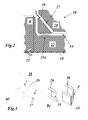
- Die Steuerung der Kühlluft-Verteilung im Rotor 22, im Stator 28 und in den Turbinenschaufeln 27 ist ein kompliziertes Unterfangen, das zusätzlich erschwert wird durch die Forderung, Rückströmungen zu vermeiden. Daraus folgt, dass eine einfache Drosselung keine gute Lösung darstellt, und dass es von Vorteil ist, eine Steuereinrichtung mit einer aerodynamisch optimierten Gestaltung einzusetzen. Solch eine Einrichtung ist die Vorwirbeldüse 24, die üblicherweise durch eine stationäre Reihe von Schaufelblättern nach Art von Turbinen-Leitschaufeln gebildet wird (Wirbelschaufeln 26 in
Fig. 3a ). Diese Wirbelschaufeln 26 sind am Stator 28 zwischen dem Verdichter 11 und dem Hochtemperaturbereich 15 befestigt. Zwischen den Wirbelschaufeln 26 ist eine Verengung 35 ausgebildet (Fig. 3b ) mit einer entsprechenden Fläche F (Fig. 3c ). - Könnte im Bereich der Vorwirbeldüse 24 eine einfache, funktionssichere selbsttätige Regelung des Massenstroms auf einfache Weise verwirklicht werden, liesse sich ohne grossen Aufwand eine besonders effektive Kühlung der entsprechenden Bereiche bei unterschiedlichen Lastzuständen der Turbine verwirklichen.
- Aus der Druckschrift
GB 2 354 290 - Aus der Druckschrift
US 2009/0226327 A1 ist eine ähnliche Lösung bekannt, bei der in den einzelnen Scheiben der Turbine Hülsen aus einer Gedächtnislegierung eingesetzt sind, die den Querschnitt von Kühlmittelkanälen temperaturabhängig verändern. - In beiden Fällen ist der Hauptstrom des Kühlmediums betroffen.
- Weiterhin offenbart die Druckschrift
GB 2 470 253 Fig. 5 ) die vorbekannte Einstellung des Hauptstroms durch die Schaufeln betrifft, bezieht sich ein anderes Ausführungsbeispiel (Fig. 4 ) auf die Steuerung eines sekundären Kühlmittelstroms im Dichtungsbereich der Rotorwelle. - Die Druckschrift
US 2002/076318 betrifft die tangentiale Eindüsung von Kühlluft von aussen in den Rotor einer Gasturbine zur Kühlung der Laufschaufeln. Die Eindüsung erfolgt unter Mischung zweier separater Ströme, von denen der eine aus dem Inneren von für die Eindüsung vorgesehenen Eindüsungs-Schaufeln abgegeben wird. Eine Steuerung durch Querschnittsänderung, insbesondere unter Einsatz einer Gedächtnislegierung, ist nicht offenbart. - Es ist eine Aufgabe der Erfindung, eine rotierende Maschine, insbesondere eine Gasturbine, zu schaffen in welcher durch Steuerung des Kühlmittel-Massenstroms in einem sekundären Kühlbereich (SAF-Secondary Air Flow) die Effizienz der Kühlung und der Wirkungsgrad der Maschine verbessert werden.
- Die Aufgabe wird durch die Gesamtheit der Merkmale des Anspruchs 1 gelöst. Die Erfindung geht aus von einer rotierenden Maschine, insbesondere Gasturbine, welche durch ein Kühlmedium, insbesondere Kühlluft, gekühlt wird, welches Kühlmedium in einem Hauptstrom und einem Sekundärstrom durch die Maschine geführt wird. Sie zeichnet sich dadurch aus, dass die rotierende Maschine einen Rotor und einen Stator umfasst, dass der Sekundärstrom des Kühlmediums durch Wirbelkanäle im Stator zu einer Vorwirbeldüse geführt wird und dort aus dem Stator austritt, dass Steuerungsmittel zur temperaturabhängigen, selbsttätigen Steuerung des Sekundärstroms im Bereich der Vorwirbeldüse angeordnet sind, und dass die Steuerungsmittel ganz oder teilweise aus einer Gedächtnislegierung bestehen.
- Eine Ausgestaltung zeichnet sich dadurch aus, dass im Bereich der Vorwirbeldüse Wirbelschaufeln angeordnet sind, und dass die Steuerungsmittel derart ausgebildet sind, dass der Strömungsquerschnitt der Wirbelkanäle im Bereich der Wirbelschaufeln temperaturabhängig veränderbar ist.
- Gemäss einer anderen Ausgestaltung umfassen die Steuerungsmittel jeweils eine in den Wirbelkanal hinein ragende, gekrümmte Membran aus einer Gedächtnislegierung, welche durch Veränderung der Krümmung den Querschnitt des Wirbelkanals verändert.
- Eine weitere Ausgestaltung der Erfindung ist dadurch gekennzeichnet, dass die Steuerungsmittel jeweils ein im Wirbelkanal wandparallel angeordnetes Wandelement umfassen, welches quer zur Wand durch aus einer Gedächtnislegierung bestehende, in Abhängigkeit von der Temperatur ihre Länge ändernde Verstellelemente verschiebbar ist und den Querschnitt des Wirbelkanals verändert.
- Insbesondere sind die Verstellelemente als Bolzen oder Federn ausgebildet.
- Eine andere Ausgestaltung zeichnet sich dadurch aus, dass das Wandelement auf der stromaufwärts gelegenen Seite mit einem Leitblech versehen ist, welches das im Wirbelkanal strömende Medium in den durch das Wandelement verengten Querschnitt einleitet.
- Eine weitere Ausgestaltung ist dadurch gekennzeichnet, dass die Wirbelschaufeln jeweils in einer den Querschnitt verändernden Weise im Wirbelkanal quer zur Strömungsrichtung verschiebbar angeordnet sind, und dass Verstellelemente aus einer Gedächtnislegierung vorgesehen sind, um die Wirbelschaufeln temperaturabhängig zu verschieben.
- Gemäss einer anderen Ausgestaltung sind die verschiebbaren Wirbelschaufeln jeweils auf der stromaufwärts gelegenen Seite mit einem Leitblech versehen, welches das im Wirbelkanal strömende Medium in den durch die Wirbelschaufeln verengten Querschnitt einleitet.
- Eine weitere Ausgestaltung der Erfindung ist dadurch gekennzeichnet, dass die Steuerungsmittel jeweils ein in Richtung der Längsachse der Wirbelschaufeln orientiertes Torsionselement aus einer Gedächtnislegierung umfassen, welches den Anstellwinkel der Wirbelschaufeln und damit den Strömungsquerschnitt temperaturabhängig verändert.
- Weiterhin ist es denkbar, dass am Austritt der Wirbelkanäle jeweils Mittel zur temperaturabhängigen Abdeckung der Austrittsöffnung angeordnet sind.
- Insbesondere können die Abdeckmittel eine temperaturgesteuerte Blende umfassen.
- Gemäss einer Ausgestaltung bestehen die Blende beziehungsweise deren Blendenelemente aus einer Gedächtnislegierung und verändern durch temperaturabhängige Änderung ihrer Abmessungen die Abdeckung der Austrittsöffnung.
- Gemäss einer anderen Ausgestaltung bestehen die Blenden jeweils aus mehreren Blendenelementen, die jeweils mit Torsionselementen aus einer Gedächtnislegierung gekoppelt sind, welche die Blendenelemente temperaturgesteuert verdrehen und so die Abdeckung der Austrittsöffnung verändern.
- Die Erfindung soll nachfolgend anhand von Ausführungsbeispielen im Zusammenhang mit der Zeichnung näher erläutert werden. Es zeigen:
- Fig. 1
- in einem Ausschnitt einen Teil einer Gasturbine mit verschiedenen Wegen für die Verteilung von Kühlluft;
- Fig. 2
- in einem vergrösserten Ausschnitt aus
Fig. 1 die Ausgestaltung des Wirbelkanals; - Fig. 3
- in verschiedenen Ansichten 3a-c die in der Vorwirbeldüse aus
Fig. 1 angeordneten Wirbelschaufeln, - Fig. 4
- in verschiedenen Teilfiguren 4b-f verschiedene Ausführungsbeispiele für eine selbsttätige Regelung des Kühlluft-Massenstroms im Wirbelkanal gemäss der Erfindung gegenüber der ungeregelten Anordnung (
Fig. 4a ); - Fig. 5
- in zwei unterschiedlichen Ansichten 5a-b ein weiteres Ausführungsbeispiel für eine selbsttätige Regelung durch Verschwenken der Wirbelschaufeln;
- Fig. 6
- im Schnitt eine weitere Möglichkeit der selbsttätigen Regelung des Kühlluft-Massenstroms im Wirbelkanal durch selbsttätige Veränderung des Austrittsquerschnitts;
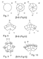
- Fig. 7
- in mehreren Teilfiguren 7a-c verschiedene Zustände bei einem Ausführungsbeispiel für eine selbsttätige Steuerung des Austrittsquerschnitts;
- Fig. 8
- in mehreren Teilfiguren 8a-b verschiedene Zustände bei einem anderen Ausführungsbeispiel für eine selbsttätige Steuerung des Austrittsquerschnitts;
- Fig. 9
- eine zu
Fig. 7 vergleichbare Ausgestaltung, bei der die einzelnen Elemente jeweils selbsttätig um eine Achse gedreht werden und - Fig. 10
- eine zu
Fig. 8 vergleichbare Ausgestaltung, bei der die einzelnen Elemente jeweils selbsttätig um eine Achse gedreht werden. - Gemäss einem bevorzugten Ausführungsbeispiel der Erfindung wird die Vorwirbeldüse 24 in einer Gasturbine 10 nach
Fig. 1 ganz oder teilweise aus einer Gedächtnislegierung (shape memory alloy SMA) aufgebaut. Unterhalb einer vorbestimmten Grenztemperatur, die niedriger sein kann als die nominale Betriebstemperatur, wird der aus einer Gedächtnislegierung bestehende Teil der Vorwirbeldüse 24 aktiviert und reduziert die Querschnittsfläche im Bereich der Verengung der Vorwirbeldüse 24, wodurch der Kühlluft-Massenstrom in den Hochtemperaturbereich 15 der Gasturbine 10 wirkungsvoll verringert wird. Hierbei kann ein Schrumpfen, ein Strecken, eine Verdrehung (Torsion) und eine Verbiegung der aus der Gedächtnislegierung bestehenden Teile als Mechanismus für die Reduzierung des Durchflussquerschnitts des ansonsten aus einem Stahl bestehenden, einfachen Systems herangezogen werden.Fig. 4 zeigt im Vergleich zur Anordnung ohne Regelung (Fig. 4a ) verschiedene Beispiele, wie durch Einsatz unterschiedlicher Anordnungen aus einer Gedächtnislegierung aufgrund unterschiedlicher Arten der mechanischen Deformation eine selbsttätig gesteuerte Vorwirbeldüse 24 realisiert werden kann (Fig. 4b-f ). Alle Beispiele basieren auf einer Reduktion der Fläche F inFig. 3c durch Reduktion der Höhe des Wirbelkanals 27 aufgrund einer translatorischen Bewegung eines oberen oder unteren Wandelements 38 oder 44 (Fig. 4c-e ), einer Membran 36 (Fig. 4b ) oder der Wirbelschaufeln 26 selbst (Fig. 4f ). - Im Beispiel der
Fig. 4b ist im Bereich der Schaufelspitze der Wirbelschaufel 26 eine in den Wirbelkanal 27 hinein gekrümmte Membran vorgesehen, deren Krümmung sich verändert und damit der Strömungsquerschnitt im Wirbelkanal 27. - Im Beispiel der
Fig. 4c ist im Bereich der Schaufelspitze der Wirbelschaufel 26 eine Verstellvorrichtung 37 mit einem wandparallelen Wandelement 38 vorgesehen, das senkrecht zur Wand durch in entsprechende Gehäuse eingebaute Verstellelemente 40 aus einer Gedächtnislegierung verschoben werden kann. Die Verstellelemente 40 können dabei die Form von Bolzen oder Federn haben. Ein in Strömungsrichtung vor dem Wandelement 38 (stromaufwärts) angeordnetes und mit dem Wandelement 38 verstellbares Leitblech 39 lenkt die Strömung in den durch das Wandelement 38 verringerten Querschnitt. - Im Beispiel der
Fig. 4d hat die Verstellvorrichtung 41 bei ansonsten gleichem Aufbau wie inFig. 4c offene Verstellelemente 42 in Form von Bolzen oder Federn. - Im Beispiel der
Fig. 4e hat die Verstellvorrichtung 43 ein auf der Seite des Schaufelfusses der Wirbelschaufel 26 angeordnetes wandparalleles Wandelement 44 mit zugeordnetem Leitblech 45, das wiederum durch Verstellelemente 42 aus einer Gedächtnislegierung senkrecht zur Wand verschoben werden kann. - Im Beispiel der
Fig. 4f wird die Wirbelschaufel 26 selbst durch entsprechende Verstellelemente 46 aus einer Gedächtnislegierung senkrecht zur Wand verschoben, um (durch Verschieben einer Plattform) den Querschnitt des Wirbelkanals 27 zu verändern. Auch hier ist ein Leitblech 47 vorgesehen, um die Strömung in den verengten Querschnitt hinein zu lenken. Selbstverständlich können die verschiedenen Verstellmechanismen derFig. 4 b-f auch miteinander kombiniert werden. - Ein weiteres Beispiel für einen geeigneten Verstellmechanismus ist in
Fig. 5 wiedergegeben, wobei die Teilfigur a) eine Seitenansicht und die Teilfigur b) eine Ansicht von oben der Wirbelschaufeln 26 zeigen. Die Wirbelschaufeln 26 in diesem Beispiel sind um eine in Schaufellängsrichtung orientierte Achse drehbar, die durch ein Torsionselement 48 aus einer Gedächtnislegierung gebildet wird. Durch entsprechende Drehung der Wirbelschaufeln 26 (siehe durchgezogene und gestrichelt Linien inFig. 5b ) verändert sich der freie Strömungsquerschnitt der Anordnung. - Eine weitere Möglichkeit besteht darin, gemäss
Fig. 6 an der Auslassöffnung des Wirbelkanals 27 eine Blende 49 anzuordnen, die ganz oder teilweise aus einer Gedächtnislegierung besteht und die Auslassöffnung temperaturbedingt verändert (siehe gestrichelte Linie zu 49 inFig. 6 ). Wenn die Leistung der Maschine reduziert und dadurch das Heissgas, die verdichtete Luft oder die Metalltemperatur irgendwelcher Teile verändert wird, schliesst sich zunehmend die Blende 49 und verringert den Massenstrom des Kühlmediums. - Besteht die Blende, wie in
Fig. 7 gezeigt, aus einer Mehrzahl von Blendenelementen 50, schliesst sich nach und nach der Ausgang des Wirbelkanals 27 wie bei der Blende eines Fotoapparats (Fig. 7a entspricht Volllast, hingegenFig. 7b-c entsprechen Teillast der Turbine). - Abhängig von der Form des Wirbelkanals 27 kann die Blende aber auch gemäss
Fig. 8 wie ein aus mehreren Blendenelementen 51 zusammengesetztes Schleusentor ausgebildet sein. Abhängig von der Temperatur verringert dieses Schleusentor, das ganz oder teilweise aus einer Gedächtnislegierung besteht, den Kühlmittelstrom im Wirbelkanal 27, oder unterbricht ihn ganz. Dabei unterliegen die einzelnen Blendenelemente 51 in Abhängigkeit von der Temperatur einer Ausdehnung 52, die den Kühlmittelstrom beeinflusst. - Es ist aber auch denkbar, die Anordnung gemäss
Fig. 7 oder Fig. 8 aus einem herkömmlichen Material herzustellen, wobei dann gemässFig. 9 oder Fig. 10 den einzelnen Blendenelementen 53 beziehungsweise 55 durch ein entsprechendes Torsionselement 54 beziehungsweise 56 aus einer Gedächtnislegierung die notwendige Drehbewegung zur Veränderung des Strömungsquerschnitts aufgeprägt wird. - Insgesamt beschreibt die vorliegende Erfindung den Einsatz von Gedächtnislegierungen im sekundären Kühlmittelsystem einer rotierenden Maschine zur die Effizienz steigernden Regelung des Kühlmittelverbrauchs in Abhängigkeit vom Lastzustand der Maschine. Die im Ausführungsbeispiel beschriebene Verwirbelung kann unterschiedliche Formen annehmen, die entsprechende Änderungen des Verstellmechanismus erfordern. Der beschriebene selbsttätige Regelungsmechanismus auf der Basis von Gedächtnislegierungen kann auch bei Hitzeschilden eingesetzt werden, um den Kühlmittelverbrauch in Abhängigkeit von der Leistung (der Gasturbine) zu steuern.
- Die vorgeschlagene Anordnung kann von einer weiteren Absenkung der Kühlmitteltemperatur relativ zur totalen Temperatur im rotierenden Referenzrahmen profitieren. Dies führt zur Möglichkeit, die benötigten Kühlluft-Massenströme weiter zu verringern und damit die Leistung und Effektivität der Gasturbine zu erhöhen.
- Die Gedächtnislegierung kann aus unterschiedlichen metallurgischen Zusammensetzungen verschiedener Elemente bestehen und auch mit unterschiedlichen Technologien hergestellt werden. Eine Veränderung der Temperatur und/oder eine mechanische Veränderung der Maschine startet den Prozess der Geometrieänderung des aus der Gedächtnislegierung bestehenden Bauteils. Im Falle einer abnehmenden Toleranz beim Zusammenbau wird das Schrumpfungsverhalten des Bauteils anstelle einer Dehnung in Betracht gezogen.
- Obgleich der vorgeschlagene Mechanismus am Beispiel einer Gasturbine erläutert worden ist, kann die Kühlmittelsteuerung auf der Basis von Elementen aus einer Gedächtnislegierung auch in anderen Maschinen eingesetzt werden, wo eine aktive selbsttätige Steuerung des Kühlmittel-Massenstroms benötigt wird.
-
- 10
- Gasturbine
- 11
- Verdichter
- 12
- Verdichterluft-Hauptstrom
- 13
- Sekundärstrom
- 14
- Kühldurchgang
- 15
- Hochtemperaturbereich
- 16
- Leitschaufel
- 17
- Laufschaufel
- 18
- Leitschaufelbefestigung
- 19
- Schaufelfuss
- 20
- Schaufelhals
- 21
- Drehgeschwindigkeit
- 22
- Rotor
- 23a-c
- Dichtungssystem
- 24
- Vorwirbeldüse
- 25
- Plattform
- 26
- Wirbelschaufel
- 27
- Wirbelkanal
- 28
- Stator
- 29
- Heissgas-Hauptstrom
- 31
- Verdichtergehäuse
- 32
- Verdichter-Leitschaufel
- 33
- Verdichter-Laufschaufel
- 34
- Maschinenachse
- 35
- Verengung
- 36
- Membran
- 37,41,43
- Verstellvorrichtung
- 38,44
- Wandelement
- 39,45,47
- Leitblech
- 40,42,46
- Verstellelement
- 48
- Torsionselement
- 49
- Blende
- 50,51,53,55
- Blendenelement
- 52
- Ausdehnung
- 54,56
- Torsionselement
- F
- Fläche
Claims (13)
- Rotierende Maschine, insbesondere Gasturbine (10), welche durch ein Kühlmedium, insbesondere Kühlluft, gekühlt wird, welches Kühlmedium in einem Hauptstrom (12) und einem Sekundärstrom (13) durch die Maschine (10) geführt wird, dadurch gekennzeichnet, dass die rotierende Maschine (10) einen Rotor (22) und einen Stator (28) umfasst, dass der Sekundärstrom (13) des Kühlmediums durch Wirbelkanäle (27) im Stator (28) zu einer Vorwirbeldüse (24) geführt wird und dort aus dem Stator (28) austritt, dass Steuerungsmittel (36-56) zur temperaturabhängigen, selbsttätigen Steuerung des Sekundärstroms (13) im Bereich der Vorwirbeldüse (24) angeordnet sind, und dass die Steuerungsmittel (36-56) ganz oder teilweise aus einer Gedächtnislegierung bestehen.
- Rotierende Maschine nach Anspruch 1, dadurch gekennzeichnet, dass im Bereich der Vorwirbeldüse (24) Wirbelschaufeln (26) angeordnet sind, und dass die Steuerungsmittel (36-48) derart ausgebildet sind, dass der Strömungsquerschnitt der Wirbelkanäle (27) im Bereich der Wirbelschaufeln (26) temperaturabhängig veränderbar ist.
- Rotierende Maschine nach Anspruch 2, dadurch gekennzeichnet, dass die Steuerungsmittel (36-47) jeweils eine in den Wirbelkanal (27) hinein ragende, gekrümmte Membran (36) aus einer Gedächtnislegierung umfassen, welche durch Veränderung der Krümmung den Querschnitt des Wirbelkanals (27) verändert.
- Rotierende Maschine nach Anspruch 2, dadurch gekennzeichnet, dass die Steuerungsmittel (36-47) jeweils ein im Wirbelkanal (27) wandparallel angeordnetes Wandelement (38, 44) umfassen, welches quer zur Wand durch aus einer Gedächtnislegierung bestehende, in Abhängigkeit von der Temperatur ihre Länge ändernde Verstellelemente (40, 42) verschiebbar ist und den Querschnitt des Wirbelkanals (27) verändert.
- Rotierende Maschine nach Anspruch 4, dadurch gekennzeichnet, dass die Verstellelemente (40, 42) als Bolzen oder Federn ausgebildet sind.
- Rotierende Maschine nach Anspruch 4 oder 5, dadurch gekennzeichnet, dass das Wandelement (38, 44) auf der stromaufwärts gelegenen Seite mit einem Leitblech (39, 45) versehen ist, welches das im Wirbelkanal (27) strömende Medium in den durch das Wandelement (38, 44) verengten Querschnitt einleitet.
- Rotierende Maschine nach Anspruch 2, dadurch gekennzeichnet, dass die Wirbelschaufeln (26) jeweils in einer den Querschnitt verändernden Weise im Wirbelkanal (27) quer zur Strömungsrichtung verschiebbar angeordnet sind, und dass Verstellelemente (46) aus einer Gedächtnislegierung vorgesehen sind, um die Wirbelschaufeln (26) temperaturabhängig zu verschieben.
- Rotierende Maschine nach Anspruch 7, dadurch gekennzeichnet, dass die verschiebbaren Wirbelschaufeln (26) jeweils auf der stromaufwärts gelegenen Seite mit einem Leitblech (47) versehen sind, welches das im Wirbelkanal (27) strömende Medium in den durch die Wirbelschaufeln (26) verengten Querschnitt einleitet.
- Rotierende Maschine nach Anspruch 2, dadurch gekennzeichnet, dass die Steuerungsmittel jeweils ein in Richtung der Längsachse der Wirbelschaufeln (26) orientiertes Torsionselement (48) aus einer Gedächtnislegierung umfassen, welches den Anstellwinkel der Wirbelschaufeln (26) und damit den Strömungsquerschnitt temperaturabhängig verändert.
- Rotierende Maschine nach Anspruch 1, dadurch gekennzeichnet, dass am Austritt der Wirbelkanäle (27) jeweils Mittel (49-51, 53-56) zur temperaturabhängigen Abdeckung der Austrittsöffnung angeordnet sind.
- Rotierende Maschine nach Anspruch 10, dadurch gekennzeichnet, dass die Abdeckmittel (49-51, 53-56) eine temperaturgesteuerte Blende (49-51, 53-56) umfassen.
- Rotierende Maschine nach Anspruch 11, dadurch gekennzeichnet, dass die Blende (49) beziehungsweise deren Blendenelemente (50, 51) aus einer Gedächtnislegierung bestehen und durch temperaturabhängige Änderung ihrer Abmessungen die Abdeckung der Austrittsöffnung verändern.
- Rotierende Maschine nach Anspruch 11, dadurch gekennzeichnet, dass die Blenden jeweils aus mehreren Blendenelementen (53, 55) bestehen, die jeweils mit Torsionselementen (54, 56) aus einer Gedächtnislegierung gekoppelt sind, welche die Blendenelemente (53, 55) temperaturgesteuert verdrehen und so die Abdeckung der Austrittsöffnung verändern.
Applications Claiming Priority (1)
| Application Number | Priority Date | Filing Date | Title |
|---|---|---|---|
| CH01947/10A CH704124A1 (de) | 2010-11-19 | 2010-11-19 | Rotierende maschine, insbesondere gasturbine. |
Publications (2)
| Publication Number | Publication Date |
|---|---|
| EP2455584A1 true EP2455584A1 (de) | 2012-05-23 |
| EP2455584B1 EP2455584B1 (de) | 2015-06-17 |
Family
ID=43478440
Family Applications (1)
| Application Number | Title | Priority Date | Filing Date |
|---|---|---|---|
| EP11187629.8A Not-in-force EP2455584B1 (de) | 2010-11-19 | 2011-11-03 | Gasturbine mit Steuerungsmittel zur Kühlung, welche teilweise aus einer Gedächtnislegierung bestehen |
Country Status (4)
| Country | Link |
|---|---|
| US (2) | US9267382B2 (de) |
| EP (1) | EP2455584B1 (de) |
| JP (1) | JP5933232B2 (de) |
| CH (1) | CH704124A1 (de) |
Cited By (3)
| Publication number | Priority date | Publication date | Assignee | Title |
|---|---|---|---|---|
| EP2679771A1 (de) * | 2012-06-25 | 2014-01-01 | General Electric Company | Systeme und Verfahren zur Steuerung der Strömung in einem Rotorrad |
| WO2014022620A1 (en) * | 2012-08-01 | 2014-02-06 | General Electric Company | Turbomachine including horizontal joint heating and method of controlling tip clearance in a gas turbomachine |
| EP3130750A1 (de) * | 2015-08-14 | 2017-02-15 | General Electric Technology GmbH | Gasturbinenkühlsysteme und -verfahren |
Families Citing this family (13)
| Publication number | Priority date | Publication date | Assignee | Title |
|---|---|---|---|---|
| US9297310B2 (en) * | 2012-10-18 | 2016-03-29 | General Electric Company | Part load performance improvement using deformable bore plugs |
| KR101595996B1 (ko) * | 2014-08-04 | 2016-02-19 | 부산대학교 산학협력단 | 가변 냉각 유로를 구비한 가스터빈 |
| US10641174B2 (en) | 2017-01-18 | 2020-05-05 | General Electric Company | Rotor shaft cooling |
| KR102028591B1 (ko) * | 2018-01-08 | 2019-10-04 | 두산중공업 주식회사 | 터빈 베인 조립체 및 이를 포함하는 가스터빈 |
| EP3587791B1 (de) | 2018-06-21 | 2021-03-24 | Claverham Limited | Durchflussregeldüse |
| US11492972B2 (en) | 2019-12-30 | 2022-11-08 | General Electric Company | Differential alpha variable area metering |
| CN112049689B (zh) * | 2020-08-19 | 2021-06-18 | 西北工业大学 | 具有错位斜向叶型接受孔的高位预旋供气系统盖板盘 |
| US11674396B2 (en) | 2021-07-30 | 2023-06-13 | General Electric Company | Cooling air delivery assembly |
| US11920500B2 (en) | 2021-08-30 | 2024-03-05 | General Electric Company | Passive flow modulation device |
| US12104501B2 (en) | 2022-01-26 | 2024-10-01 | General Electric Company | Cantilevered airfoils and methods of forming the same |
| US11692448B1 (en) | 2022-03-04 | 2023-07-04 | General Electric Company | Passive valve assembly for a nozzle of a gas turbine engine |
| US11781444B1 (en) | 2022-06-03 | 2023-10-10 | General Electric Company | Adaptive orifice assembly for controlling airflow in a gas turbine engine |
| US12291997B1 (en) | 2024-04-30 | 2025-05-06 | General Electric Company | Variable area turbine nozzle assembly |
Citations (5)
| Publication number | Priority date | Publication date | Assignee | Title |
|---|---|---|---|---|
| GB2354290A (en) | 1999-09-18 | 2001-03-21 | Rolls Royce Plc | Gas turbine cooling air flow control using shaped memory metal valve |
| US20020076318A1 (en) | 2000-12-18 | 2002-06-20 | Kiritkumar Patel | Further cooling of pre-swirl flow entering cooled rotor aerofoils |
| EP1843030A2 (de) * | 2006-04-05 | 2007-10-10 | Rolls-Royce plc | Durchflusssteuervorrichtung |
| US20090226327A1 (en) | 2008-03-07 | 2009-09-10 | Siemens Power Generation, Inc. | Gas Turbine Engine Including Temperature Control Device and Method Using Memory Metal |
| GB2470253A (en) | 2009-05-15 | 2010-11-17 | Rolls Royce Plc | Temperature responsive fluid flow control device |
Family Cites Families (12)
| Publication number | Priority date | Publication date | Assignee | Title |
|---|---|---|---|---|
| US4296599A (en) * | 1979-03-30 | 1981-10-27 | General Electric Company | Turbine cooling air modulation apparatus |
| US4393654A (en) * | 1979-07-10 | 1983-07-19 | Pelly L Ronald | Shape memory element engine |
| US4375891A (en) | 1980-05-10 | 1983-03-08 | Rolls-Royce Limited | Seal between a turbine rotor of a gas turbine engine and associated static structure of the engine |
| DE3542762A1 (de) * | 1985-12-04 | 1987-06-11 | Mtu Muenchen Gmbh | Einrichtung zur steuerung oder regelung von gasturbinentriebwerken bzw. gasturbinenstrahltriebwerken |
| FR2604750B1 (fr) * | 1986-10-01 | 1988-12-02 | Snecma | Turbomachine munie d'un dispositif de commande automatique des debits de ventilation de turbine |
| US5022817A (en) * | 1989-09-12 | 1991-06-11 | Allied-Signal Inc. | Thermostatic control of turbine cooling air |
| JPH08296455A (ja) | 1995-04-27 | 1996-11-12 | Ishikawajima Harima Heavy Ind Co Ltd | ターボエンジン |
| DE19756734A1 (de) * | 1997-12-19 | 1999-06-24 | Bmw Rolls Royce Gmbh | Passives Spalthaltungssystem einer Gasturbine |
| GB0403198D0 (en) * | 2004-02-13 | 2004-03-17 | Rolls Royce Plc | Casing arrangement |
| ATE390587T1 (de) * | 2005-09-08 | 2008-04-15 | Fiat Ricerche | Membraneventil mit formgedächtnisbetätigung |
| US8079803B2 (en) | 2008-06-30 | 2011-12-20 | Mitsubishi Heavy Industries, Ltd. | Gas turbine and cooling air supply structure thereof |
| GB0818047D0 (en) | 2008-10-03 | 2008-11-05 | Rolls Royce Plc | Turbine cooling system |
-
2010
- 2010-11-19 CH CH01947/10A patent/CH704124A1/de not_active Application Discontinuation
-
2011
- 2011-11-03 EP EP11187629.8A patent/EP2455584B1/de not_active Not-in-force
- 2011-11-16 US US13/297,288 patent/US9267382B2/en not_active Expired - Fee Related
- 2011-11-21 JP JP2011253752A patent/JP5933232B2/ja not_active Expired - Fee Related
-
2016
- 2016-01-27 US US15/007,542 patent/US20160138410A1/en not_active Abandoned
Patent Citations (5)
| Publication number | Priority date | Publication date | Assignee | Title |
|---|---|---|---|---|
| GB2354290A (en) | 1999-09-18 | 2001-03-21 | Rolls Royce Plc | Gas turbine cooling air flow control using shaped memory metal valve |
| US20020076318A1 (en) | 2000-12-18 | 2002-06-20 | Kiritkumar Patel | Further cooling of pre-swirl flow entering cooled rotor aerofoils |
| EP1843030A2 (de) * | 2006-04-05 | 2007-10-10 | Rolls-Royce plc | Durchflusssteuervorrichtung |
| US20090226327A1 (en) | 2008-03-07 | 2009-09-10 | Siemens Power Generation, Inc. | Gas Turbine Engine Including Temperature Control Device and Method Using Memory Metal |
| GB2470253A (en) | 2009-05-15 | 2010-11-17 | Rolls Royce Plc | Temperature responsive fluid flow control device |
Cited By (8)
| Publication number | Priority date | Publication date | Assignee | Title |
|---|---|---|---|---|
| EP2679771A1 (de) * | 2012-06-25 | 2014-01-01 | General Electric Company | Systeme und Verfahren zur Steuerung der Strömung in einem Rotorrad |
| CN103511083A (zh) * | 2012-06-25 | 2014-01-15 | 通用电气公司 | 用于控制转子叶轮中的流的系统和方法 |
| US9188010B2 (en) | 2012-06-25 | 2015-11-17 | General Electric Company | Systems and methods to control flow in a rotor wheel |
| CN103511083B (zh) * | 2012-06-25 | 2017-04-12 | 通用电气公司 | 用于控制转子叶轮中的流的系统和方法 |
| WO2014022620A1 (en) * | 2012-08-01 | 2014-02-06 | General Electric Company | Turbomachine including horizontal joint heating and method of controlling tip clearance in a gas turbomachine |
| US9127558B2 (en) | 2012-08-01 | 2015-09-08 | General Electric Company | Turbomachine including horizontal joint heating and method of controlling tip clearance in a gas turbomachine |
| EP3130750A1 (de) * | 2015-08-14 | 2017-02-15 | General Electric Technology GmbH | Gasturbinenkühlsysteme und -verfahren |
| US10724382B2 (en) | 2015-08-14 | 2020-07-28 | Ansaldo Energia Switzerland AG | Gas turbine cooling systems and methods |
Also Published As
| Publication number | Publication date |
|---|---|
| US20160138410A1 (en) | 2016-05-19 |
| JP5933232B2 (ja) | 2016-06-08 |
| US9267382B2 (en) | 2016-02-23 |
| JP2012112382A (ja) | 2012-06-14 |
| CH704124A1 (de) | 2012-05-31 |
| US20120128473A1 (en) | 2012-05-24 |
| EP2455584B1 (de) | 2015-06-17 |
Similar Documents
| Publication | Publication Date | Title |
|---|---|---|
| EP2455584B1 (de) | Gasturbine mit Steuerungsmittel zur Kühlung, welche teilweise aus einer Gedächtnislegierung bestehen | |
| EP2770260B1 (de) | Gasturbinenbrennkammer mit Prall-effusionsgekühlter Schindel | |
| EP3186498B1 (de) | Gasturbinenanordnung | |
| DE3941174C2 (de) | Spitzenspalt-Einstellvorrichtung für die Turbinenrotorschaufeln eines Gasturbinentriebwerks | |
| EP2132414B1 (de) | Shiplap-anordnung | |
| EP2450531B1 (de) | Axialverdichterkühlung | |
| EP3093447B1 (de) | Rotor einer turbine einer gasturbine mit verbesserter kühlluftführung | |
| DE19756734A1 (de) | Passives Spalthaltungssystem einer Gasturbine | |
| EP2434164A1 (de) | Verstellbares Casing Treatment | |
| EP3000984A1 (de) | Leitschaufelverstellvorrichtung einer gasturbine | |
| EP0992656B1 (de) | Strömungsmaschine zum Verdichten oder Entspannen eines komprimierbaren Mediums | |
| WO2014033220A1 (de) | Kühlverfahren zum betreiben einer gasturbine | |
| EP0508067A1 (de) | Vorrichtung zum Regulieren des durchströmten Querschnitts einer Turbomaschine | |
| DE19839592A1 (de) | Strömungsmaschine mit gekühlter Rotorwelle | |
| DE3248439A1 (de) | Gasturbinentriebwerk mit gekuehlten schaufelspitzen | |
| WO2016055354A1 (de) | Gasturbine mit zwei drallzuleitungen zur kühlung des rotors | |
| EP2146056A2 (de) | Gasturbinentriebwerk mit verstellbaren Leitschaufeln | |
| EP3159487A1 (de) | Stator einer turbine einer gasturbine mit verbesserter kühlluftführung | |
| EP2189630A1 (de) | Gasturbine, Leitschaufelträger für eine solche Gasturbine und Gas- bzw. Dampfturbinenanlage mit einer solchen Gasturbine | |
| EP3321589A1 (de) | Treibstoffdüse einer gasturbine mit drallerzeuger | |
| EP2696040B1 (de) | Strömungsleitanordnung zur Kühlung des Niederdruckturbinengehäuses eines Gasturbinenstrahltriebwerk | |
| DE10352789B4 (de) | Gasturbine | |
| DE102005045255A1 (de) | Verbesserter Verdichter in Axialbauart | |
| EP2434163A1 (de) | Verdichter | |
| WO2006072528A1 (de) | Gasturbine mit einem vordrallerzeuger sowie ein verfahren zum betreiben einer gasturbine |
Legal Events
| Date | Code | Title | Description |
|---|---|---|---|
| PUAI | Public reference made under article 153(3) epc to a published international application that has entered the european phase |
Free format text: ORIGINAL CODE: 0009012 |
|
| AK | Designated contracting states |
Kind code of ref document: A1 Designated state(s): AL AT BE BG CH CY CZ DE DK EE ES FI FR GB GR HR HU IE IS IT LI LT LU LV MC MK MT NL NO PL PT RO RS SE SI SK SM TR |
|
| AX | Request for extension of the european patent |
Extension state: BA ME |
|
| 17P | Request for examination filed |
Effective date: 20121113 |
|
| GRAP | Despatch of communication of intention to grant a patent |
Free format text: ORIGINAL CODE: EPIDOSNIGR1 |
|
| INTG | Intention to grant announced |
Effective date: 20150205 |
|
| GRAS | Grant fee paid |
Free format text: ORIGINAL CODE: EPIDOSNIGR3 |
|
| GRAA | (expected) grant |
Free format text: ORIGINAL CODE: 0009210 |
|
| AK | Designated contracting states |
Kind code of ref document: B1 Designated state(s): AL AT BE BG CH CY CZ DE DK EE ES FI FR GB GR HR HU IE IS IT LI LT LU LV MC MK MT NL NO PL PT RO RS SE SI SK SM TR |
|
| REG | Reference to a national code |
Ref country code: GB Ref legal event code: FG4D Free format text: NOT ENGLISH |
|
| REG | Reference to a national code |
Ref country code: CH Ref legal event code: EP |
|
| REG | Reference to a national code |
Ref country code: AT Ref legal event code: REF Ref document number: 732050 Country of ref document: AT Kind code of ref document: T Effective date: 20150715 |
|
| REG | Reference to a national code |
Ref country code: IE Ref legal event code: FG4D Free format text: LANGUAGE OF EP DOCUMENT: GERMAN |
|
| REG | Reference to a national code |
Ref country code: DE Ref legal event code: R096 Ref document number: 502011007089 Country of ref document: DE |
|
| PG25 | Lapsed in a contracting state [announced via postgrant information from national office to epo] |
Ref country code: HR Free format text: LAPSE BECAUSE OF FAILURE TO SUBMIT A TRANSLATION OF THE DESCRIPTION OR TO PAY THE FEE WITHIN THE PRESCRIBED TIME-LIMIT Effective date: 20150617 Ref country code: LT Free format text: LAPSE BECAUSE OF FAILURE TO SUBMIT A TRANSLATION OF THE DESCRIPTION OR TO PAY THE FEE WITHIN THE PRESCRIBED TIME-LIMIT Effective date: 20150617 Ref country code: FI Free format text: LAPSE BECAUSE OF FAILURE TO SUBMIT A TRANSLATION OF THE DESCRIPTION OR TO PAY THE FEE WITHIN THE PRESCRIBED TIME-LIMIT Effective date: 20150617 Ref country code: NO Free format text: LAPSE BECAUSE OF FAILURE TO SUBMIT A TRANSLATION OF THE DESCRIPTION OR TO PAY THE FEE WITHIN THE PRESCRIBED TIME-LIMIT Effective date: 20150917 |
|
| REG | Reference to a national code |
Ref country code: LT Ref legal event code: MG4D Ref country code: NL Ref legal event code: MP Effective date: 20150617 |
|
| PG25 | Lapsed in a contracting state [announced via postgrant information from national office to epo] |
Ref country code: RS Free format text: LAPSE BECAUSE OF FAILURE TO SUBMIT A TRANSLATION OF THE DESCRIPTION OR TO PAY THE FEE WITHIN THE PRESCRIBED TIME-LIMIT Effective date: 20150617 Ref country code: LV Free format text: LAPSE BECAUSE OF FAILURE TO SUBMIT A TRANSLATION OF THE DESCRIPTION OR TO PAY THE FEE WITHIN THE PRESCRIBED TIME-LIMIT Effective date: 20150617 Ref country code: BG Free format text: LAPSE BECAUSE OF FAILURE TO SUBMIT A TRANSLATION OF THE DESCRIPTION OR TO PAY THE FEE WITHIN THE PRESCRIBED TIME-LIMIT Effective date: 20150917 Ref country code: GR Free format text: LAPSE BECAUSE OF FAILURE TO SUBMIT A TRANSLATION OF THE DESCRIPTION OR TO PAY THE FEE WITHIN THE PRESCRIBED TIME-LIMIT Effective date: 20150918 |
|
| PG25 | Lapsed in a contracting state [announced via postgrant information from national office to epo] |
Ref country code: EE Free format text: LAPSE BECAUSE OF FAILURE TO SUBMIT A TRANSLATION OF THE DESCRIPTION OR TO PAY THE FEE WITHIN THE PRESCRIBED TIME-LIMIT Effective date: 20150617 |
|
| PG25 | Lapsed in a contracting state [announced via postgrant information from national office to epo] |
Ref country code: PL Free format text: LAPSE BECAUSE OF FAILURE TO SUBMIT A TRANSLATION OF THE DESCRIPTION OR TO PAY THE FEE WITHIN THE PRESCRIBED TIME-LIMIT Effective date: 20150617 Ref country code: SK Free format text: LAPSE BECAUSE OF FAILURE TO SUBMIT A TRANSLATION OF THE DESCRIPTION OR TO PAY THE FEE WITHIN THE PRESCRIBED TIME-LIMIT Effective date: 20150617 Ref country code: IS Free format text: LAPSE BECAUSE OF FAILURE TO SUBMIT A TRANSLATION OF THE DESCRIPTION OR TO PAY THE FEE WITHIN THE PRESCRIBED TIME-LIMIT Effective date: 20151017 Ref country code: CZ Free format text: LAPSE BECAUSE OF FAILURE TO SUBMIT A TRANSLATION OF THE DESCRIPTION OR TO PAY THE FEE WITHIN THE PRESCRIBED TIME-LIMIT Effective date: 20150617 Ref country code: ES Free format text: LAPSE BECAUSE OF FAILURE TO SUBMIT A TRANSLATION OF THE DESCRIPTION OR TO PAY THE FEE WITHIN THE PRESCRIBED TIME-LIMIT Effective date: 20150617 Ref country code: RO Free format text: LAPSE BECAUSE OF NON-PAYMENT OF DUE FEES Effective date: 20150617 Ref country code: PT Free format text: LAPSE BECAUSE OF FAILURE TO SUBMIT A TRANSLATION OF THE DESCRIPTION OR TO PAY THE FEE WITHIN THE PRESCRIBED TIME-LIMIT Effective date: 20151019 |
|
| REG | Reference to a national code |
Ref country code: DE Ref legal event code: R097 Ref document number: 502011007089 Country of ref document: DE |
|
| PLBE | No opposition filed within time limit |
Free format text: ORIGINAL CODE: 0009261 |
|
| STAA | Information on the status of an ep patent application or granted ep patent |
Free format text: STATUS: NO OPPOSITION FILED WITHIN TIME LIMIT |
|
| PG25 | Lapsed in a contracting state [announced via postgrant information from national office to epo] |
Ref country code: DK Free format text: LAPSE BECAUSE OF FAILURE TO SUBMIT A TRANSLATION OF THE DESCRIPTION OR TO PAY THE FEE WITHIN THE PRESCRIBED TIME-LIMIT Effective date: 20150617 |
|
| 26N | No opposition filed |
Effective date: 20160318 |
|
| PG25 | Lapsed in a contracting state [announced via postgrant information from national office to epo] |
Ref country code: MC Free format text: LAPSE BECAUSE OF FAILURE TO SUBMIT A TRANSLATION OF THE DESCRIPTION OR TO PAY THE FEE WITHIN THE PRESCRIBED TIME-LIMIT Effective date: 20150617 Ref country code: LU Free format text: LAPSE BECAUSE OF FAILURE TO SUBMIT A TRANSLATION OF THE DESCRIPTION OR TO PAY THE FEE WITHIN THE PRESCRIBED TIME-LIMIT Effective date: 20151103 |
|
| REG | Reference to a national code |
Ref country code: CH Ref legal event code: PL |
|
| PG25 | Lapsed in a contracting state [announced via postgrant information from national office to epo] |
Ref country code: CH Free format text: LAPSE BECAUSE OF NON-PAYMENT OF DUE FEES Effective date: 20151130 Ref country code: LI Free format text: LAPSE BECAUSE OF NON-PAYMENT OF DUE FEES Effective date: 20151130 |
|
| REG | Reference to a national code |
Ref country code: DE Ref legal event code: R081 Ref document number: 502011007089 Country of ref document: DE Owner name: GENERAL ELECTRIC TECHNOLOGY GMBH, CH Free format text: FORMER OWNER: ALSTOM TECHNOLOGY LTD., BADEN, CH Ref country code: DE Ref legal event code: R081 Ref document number: 502011007089 Country of ref document: DE Owner name: ANSALDO ENERGIA SWITZERLAND AG, CH Free format text: FORMER OWNER: ALSTOM TECHNOLOGY LTD., BADEN, CH |
|
| REG | Reference to a national code |
Ref country code: IE Ref legal event code: MM4A |
|
| REG | Reference to a national code |
Ref country code: FR Ref legal event code: ST Effective date: 20160729 |
|
| PG25 | Lapsed in a contracting state [announced via postgrant information from national office to epo] |
Ref country code: SI Free format text: LAPSE BECAUSE OF FAILURE TO SUBMIT A TRANSLATION OF THE DESCRIPTION OR TO PAY THE FEE WITHIN THE PRESCRIBED TIME-LIMIT Effective date: 20150617 |
|
| PG25 | Lapsed in a contracting state [announced via postgrant information from national office to epo] |
Ref country code: IE Free format text: LAPSE BECAUSE OF NON-PAYMENT OF DUE FEES Effective date: 20151103 |
|
| PG25 | Lapsed in a contracting state [announced via postgrant information from national office to epo] |
Ref country code: FR Free format text: LAPSE BECAUSE OF NON-PAYMENT OF DUE FEES Effective date: 20151130 |
|
| PG25 | Lapsed in a contracting state [announced via postgrant information from national office to epo] |
Ref country code: HU Free format text: LAPSE BECAUSE OF FAILURE TO SUBMIT A TRANSLATION OF THE DESCRIPTION OR TO PAY THE FEE WITHIN THE PRESCRIBED TIME-LIMIT; INVALID AB INITIO Effective date: 20111103 Ref country code: SM Free format text: LAPSE BECAUSE OF FAILURE TO SUBMIT A TRANSLATION OF THE DESCRIPTION OR TO PAY THE FEE WITHIN THE PRESCRIBED TIME-LIMIT Effective date: 20150617 |
|
| PG25 | Lapsed in a contracting state [announced via postgrant information from national office to epo] |
Ref country code: NL Free format text: LAPSE BECAUSE OF FAILURE TO SUBMIT A TRANSLATION OF THE DESCRIPTION OR TO PAY THE FEE WITHIN THE PRESCRIBED TIME-LIMIT Effective date: 20150617 Ref country code: SE Free format text: LAPSE BECAUSE OF FAILURE TO SUBMIT A TRANSLATION OF THE DESCRIPTION OR TO PAY THE FEE WITHIN THE PRESCRIBED TIME-LIMIT Effective date: 20150617 Ref country code: CY Free format text: LAPSE BECAUSE OF FAILURE TO SUBMIT A TRANSLATION OF THE DESCRIPTION OR TO PAY THE FEE WITHIN THE PRESCRIBED TIME-LIMIT Effective date: 20150617 |
|
| PG25 | Lapsed in a contracting state [announced via postgrant information from national office to epo] |
Ref country code: BE Free format text: LAPSE BECAUSE OF NON-PAYMENT OF DUE FEES Effective date: 20151130 |
|
| REG | Reference to a national code |
Ref country code: GB Ref legal event code: 732E Free format text: REGISTERED BETWEEN 20170727 AND 20170802 |
|
| PG25 | Lapsed in a contracting state [announced via postgrant information from national office to epo] |
Ref country code: TR Free format text: LAPSE BECAUSE OF FAILURE TO SUBMIT A TRANSLATION OF THE DESCRIPTION OR TO PAY THE FEE WITHIN THE PRESCRIBED TIME-LIMIT Effective date: 20150617 Ref country code: MT Free format text: LAPSE BECAUSE OF FAILURE TO SUBMIT A TRANSLATION OF THE DESCRIPTION OR TO PAY THE FEE WITHIN THE PRESCRIBED TIME-LIMIT Effective date: 20150617 |
|
| REG | Reference to a national code |
Ref country code: DE Ref legal event code: R081 Ref document number: 502011007089 Country of ref document: DE Owner name: ANSALDO ENERGIA SWITZERLAND AG, CH Free format text: FORMER OWNER: GENERAL ELECTRIC TECHNOLOGY GMBH, BADEN, CH |
|
| REG | Reference to a national code |
Ref country code: AT Ref legal event code: MM01 Ref document number: 732050 Country of ref document: AT Kind code of ref document: T Effective date: 20161103 |
|
| PG25 | Lapsed in a contracting state [announced via postgrant information from national office to epo] |
Ref country code: AT Free format text: LAPSE BECAUSE OF NON-PAYMENT OF DUE FEES Effective date: 20161103 |
|
| PGFP | Annual fee paid to national office [announced via postgrant information from national office to epo] |
Ref country code: DE Payment date: 20171121 Year of fee payment: 7 |
|
| PGFP | Annual fee paid to national office [announced via postgrant information from national office to epo] |
Ref country code: IT Payment date: 20171124 Year of fee payment: 7 Ref country code: GB Payment date: 20171123 Year of fee payment: 7 |
|
| PG25 | Lapsed in a contracting state [announced via postgrant information from national office to epo] |
Ref country code: MK Free format text: LAPSE BECAUSE OF FAILURE TO SUBMIT A TRANSLATION OF THE DESCRIPTION OR TO PAY THE FEE WITHIN THE PRESCRIBED TIME-LIMIT Effective date: 20150617 |
|
| PG25 | Lapsed in a contracting state [announced via postgrant information from national office to epo] |
Ref country code: AL Free format text: LAPSE BECAUSE OF FAILURE TO SUBMIT A TRANSLATION OF THE DESCRIPTION OR TO PAY THE FEE WITHIN THE PRESCRIBED TIME-LIMIT Effective date: 20150617 |
|
| REG | Reference to a national code |
Ref country code: DE Ref legal event code: R119 Ref document number: 502011007089 Country of ref document: DE |
|
| GBPC | Gb: european patent ceased through non-payment of renewal fee |
Effective date: 20181103 |
|
| PG25 | Lapsed in a contracting state [announced via postgrant information from national office to epo] |
Ref country code: IT Free format text: LAPSE BECAUSE OF NON-PAYMENT OF DUE FEES Effective date: 20181103 Ref country code: DE Free format text: LAPSE BECAUSE OF NON-PAYMENT OF DUE FEES Effective date: 20190601 |
|
| PG25 | Lapsed in a contracting state [announced via postgrant information from national office to epo] |
Ref country code: GB Free format text: LAPSE BECAUSE OF NON-PAYMENT OF DUE FEES Effective date: 20181103 |