EP2455284A2 - Belüftungssystem und Flugzeugklimaanlage - Google Patents
Belüftungssystem und Flugzeugklimaanlage Download PDFInfo
- Publication number
- EP2455284A2 EP2455284A2 EP11009072A EP11009072A EP2455284A2 EP 2455284 A2 EP2455284 A2 EP 2455284A2 EP 11009072 A EP11009072 A EP 11009072A EP 11009072 A EP11009072 A EP 11009072A EP 2455284 A2 EP2455284 A2 EP 2455284A2
- Authority
- EP
- European Patent Office
- Prior art keywords
- air
- chamber housing
- air supply
- supply pipe
- ventilation system
- Prior art date
- Legal status (The legal status is an assumption and is not a legal conclusion. Google has not performed a legal analysis and makes no representation as to the accuracy of the status listed.)
- Withdrawn
Links
Images


Classifications
-
- B—PERFORMING OPERATIONS; TRANSPORTING
- B64—AIRCRAFT; AVIATION; COSMONAUTICS
- B64D—EQUIPMENT FOR FITTING IN OR TO AIRCRAFT; FLIGHT SUITS; PARACHUTES; ARRANGEMENT OR MOUNTING OF POWER PLANTS OR PROPULSION TRANSMISSIONS IN AIRCRAFT
- B64D13/00—Arrangements or adaptations of air-treatment apparatus for aircraft crew or passengers, or freight space
-
- B—PERFORMING OPERATIONS; TRANSPORTING
- B64—AIRCRAFT; AVIATION; COSMONAUTICS
- B64D—EQUIPMENT FOR FITTING IN OR TO AIRCRAFT; FLIGHT SUITS; PARACHUTES; ARRANGEMENT OR MOUNTING OF POWER PLANTS OR PROPULSION TRANSMISSIONS IN AIRCRAFT
- B64D13/00—Arrangements or adaptations of air-treatment apparatus for aircraft crew or passengers, or freight space
- B64D2013/003—Cabin ventilation nozzles
Definitions
- the invention relates to a ventilation system provided for mounting in an aircraft passenger cabin, in particular an individual ventilation system and an aircraft air conditioning system equipped with such a ventilation system.
- Modern commercial aircraft are usually equipped with an individual ventilation system that supplies the passengers in the passenger cabin of the aircraft individually with provided by an aircraft air conditioning conditioning air.
- a current individual ventilation system includes an individual air supply tube extending in the aircraft passenger cabin in an area beneath luggage compartments for receiving passengers' carry-on luggage or in the region of a side wall of the passenger cabin substantially parallel to a longitudinal axis of the aircraft passenger cabin.
- the individual air supply pipe is traversed by air conditioning air which is supplied to the individual air supply pipe from an air conditioning air generating device of the aircraft air conditioning system.
- the air duct consists of a rectilinear dimensionally stable hollow profile with a longitudinal slot, wherein the longitudinal slot is sealed by a sealing lip.
- the carriage For removing the air guided in the longitudinal direction of the air duct carriage is provided with a projecting into an interior of the hollow profile sampling neck.
- the carriage has an outer guide and an inner guide, which are firmly connected to the sampling connection and are arranged at a distance from one another such that they form a space adapted to the sealing lip.
- the DE 10 2010 018 502 relates to a supply system for supplying passengers on board an aircraft, comprising a supply line and a plurality of supply modules, which are connectable to a supply opening of the supply line for supplying the passengers.
- the supply modules are displaceable relative to each other along the supply line.
- Each supply module is associated with a shutter which is displaceable along the supply line to cover a supply opening not used to connect a supply module to the supply line.
- the invention is directed to the object of providing an easy-to-install and, if necessary, easily reconfigurable ventilation system for an aircraft passenger cabin. Furthermore, the invention is directed to the task of specifying an aircraft air conditioning system equipped with such a ventilation system.
- An inventive ventilation system provided for installation in an aircraft passenger cabin comprises an air supply pipe which has a plurality of air outlet openings arranged distributed along its longitudinal axis.
- the air supply pipe is preferably designed in the form of a rigid tube and may for example consist of an extruded plastic material.
- the cross section of the air supply pipe can, as needed, be adapted to the installation space conditions in the aircraft passenger cabin and, for example, be rectangular, round or oval.
- the air outlet openings of the air supply pipe are arranged one behind the other substantially distributed in a line along the longitudinal axis of the air supply pipe. If necessary, however, an offset arrangement of the air outlet openings is also conceivable.
- the air supply pipe is preferably connected to an air conditioning air generating device of an aircraft air conditioning system, so that the air supply pipe is traversed in the operation of the ventilation system according to the invention of air conditioning air, which is supplied to the air supply pipe from the air conditioning air conditioning device of the aircraft air conditioning.
- the ventilation system according to the invention further comprises an air chamber housing, which is connectable along the longitudinal axis of the air supply pipe at different positions with the air supply pipe.
- the connection of the air chamber housing with the air supply pipe takes place in such a way that the air supply air flowing through the air supply pipe can be fed into the air chamber housing through an air outlet opening provided in the air supply pipe.
- the air chamber housing is preferably attached to the air supply pipe such that the air chamber housing covers at least one air outlet opening of the air supply pipe.
- the air chamber housing can have any shape.
- the air chamber housing has an elongate shape, so that the air chamber housing can be displaced over a longer distance along the longitudinal axis of the air supply pipe, but still covers the air outlet formed in the air supply pipe.
- the longitudinal extent of the air chamber housing but preferably less than the distance between two mutually adjacent air outlet openings of the air supply pipe.
- the ventilation system comprises a connection device, which is set up to connect the air chamber housing with an air supply device for supplying air conditioning air into the aircraft passenger cabin.
- the air supply device for supplying air conditioning air into the aircraft passenger cabin can be, for example, an individually operable air shower of an individual ventilation system.
- the air supply device may also be an air supply device of a centrally controlled subsystem of the cabin ventilation system.
- the ventilation system according to the invention enables a simple and flexible connection of air supply devices arranged at different positions in the aircraft passenger cabin for supplying air conditioning air in aircraft passenger cabins to the air supply pipe by corresponding positioning of the air chamber housing along the longitudinal axis of the air supply pipe.
- the provision of different lengths of flexible hoses, as used for example in conventional individual ventilation systems, can therefore be dispensed with in the ventilation system according to the invention.
- the provision of appropriate receptacles for the tubes is also no longer required.
- the flexible positioning of the air chamber housing along the longitudinal axis of the air supply tube allows for the elimination of the provision of double air outlets on the air supply pipe and double air inlets on the supply apparatus for supplying air conditioning air into the aircraft passenger cabin.
- the ventilation system according to the invention is thus characterized by a low weight and easy mountability. Furthermore, the ventilation system can be reconfigured with little effort in the context of a reconfiguration of the aircraft passenger cabin.
- the advantage of the simple reconfigurability of the ventilation system is particularly useful if the ventilation system according to the invention is designed as an individual ventilation system. In principle, however, the ventilation system according to the invention can also be embodied in the form of a centrally controlled subsystem of the passenger cabin ventilation system of the aircraft.
- the air chamber housing preferably includes an open port area bounded by a side wall portion of the air chamber housing and configured to restrict the supply of air discharged from an air outlet port of the air supply pipe To allow air conditioning air in the air chamber housing.
- the air chamber housing may have a semicircular or semi-oval cross-section open in its connection region. It is understood, however, that the air chamber housing can also have a polygonal cross-section.
- the air chamber housing comprises a sealing element which extends along an edge of the side wall region of the air chamber housing facing the air supply pipe.
- the sealing element is an encircling sealing element which allows the air chamber housing to be sealed against the environment along the entire edge of the side wall region of the air chamber housing facing the air supply pipe. In the state connected to the air supply pipe, the sealing element preferably cooperates with an outer surface of the air supply pipe.
- the air supply pipe comprises a guide device extending along its longitudinal axis, which is set up to allow a guided displacement of the air chamber housing along the longitudinal axis of the air supply pipe.
- a guide device provided on the air supply pipe permits a particularly simple assembly and / or reconfiguration of the ventilation system according to the invention.
- the guide device may, for example, comprise two guide rails extending along the longitudinal axis of the air supply pipe and substantially parallel to each other.
- the guide rails may project from an outer surface of the air supply pipe toward the air chamber housing and cooperate with outer surfaces of two opposing side wall portion portions of the air chamber housing to allow guided displacement of the air chamber housing along the longitudinal axis of the air supply pipe.
- the ventilation system according to the invention further comprises a locking device for locking the air chamber housing in a desired position along the longitudinal axis of the air supply pipe.
- the locking device ensures that the air chamber housing is securely fixed in a desired position along the longitudinal axis of the air supply pipe.
- the locking device comprises a locking element, which is movably connected between an unlocked position and a locking position with the air chamber housing and in its locking position with a provided on the air supply pipe receiving device is engageable.
- the locking element can then be brought into its unlocked position, whereby an unhindered movement of the air chamber housing along the longitudinal axis of the air supply pipe, but also a complete release of the air chamber housing from the air supply pipe is possible.
- the locking member can be moved to its locking position to fix the air chamber housing to the air supply pipe.
- the receiving device provided on the air supply pipe preferably comprises at least one receiving groove.
- the receiving groove may be formed on the guide device extending along the longitudinal axis of the air supply pipe.
- two guide rails of the guide device extending along the longitudinal axis of the air supply pipe and extending substantially parallel to one another are each provided with a receiving groove.
- the locking element can then be designed in the form of a rotatably connected to the air chamber housing locking element. In the unlocked position of the locking element, the locking element is out of engagement with the receiving grooves of the receiving device. By contrast, when the locking element is in its locking position, edge portions of the locking element engage in the receiving grooves of the receiving device.
- the locking element of the locking device is adapted to apply in its locking position, a force on the air chamber housing, which presses the air chamber housing against the air supply pipe.
- the locking member then not only fulfills the function of fixing the air chamber housing in a desired position on the air supply pipe, but also pushes the sealing element of the air chamber housing against the outer surface of the air supply pipe and thus contributes to the air chamber housing is sealingly connected to the air supply pipe.
- the locking element is preferably designed in the form of a locking clip which spans the air chamber housing in its locking position at least in sections.
- Such executed locking element is simple in construction, but still not only allows a secure fixation of the air chamber housing to the air supply pipe, but also makes it possible to apply a the air chamber housing against the air supply pipe pushing force on the air chamber housing.
- closure devices are sealingly closed in the ventilation system according to the invention preferably by means of appropriate closure devices. This prevents the air supply air flowing through the air supply pipe from undesirably leaking from the air supply pipe.
- the closure devices may for example be designed in the form of screw caps, plugs or the like.
- connection device of the ventilation system preferably has a plurality of connection openings for connecting the air chamber housing to an air supply device for supplying air conditioning air into the aircraft passenger cabin.
- a first connection opening of the connection device can be arranged such that it can be flowed through by climate-forming air substantially perpendicular to the longitudinal axis of the air supply pipe.
- a second connection opening of the connection device can be arranged such that it can be flowed through by air conditioning air substantially parallel to the longitudinal axis of the air supply pipe.
- connection opening of the connection device which is not connected to an air supply device for supplying air conditioning air into the aircraft passenger cabin is preferably sealingly closed by means of a corresponding closure device. This prevents air conditioning air from undesirably escaping from the air chamber housing.
- a closure device a screw cap or a plug can be used.
- connection openings of the connection device it is possible to connect all connection openings of the connection device to one or more supply devices for supplying air conditioning air to connect to the aircraft passenger cabin.
- one connection port of the connection device is connected to an air supply device for supplying air conditioning air into the aircraft passenger cabin.
- the more favorably arranged connection opening of the connection device can be used to connect the air chamber housing to the air supply device.
- a first connection opening of the connection device which can be flowed through by air conditioning air substantially perpendicularly to the longitudinal axis of the air supply pipe can be directly connected to the air supply device, while a second connection opening of the connection device through which the air conditioning air flows parallel to the longitudinal axis of the air supply pipe can be sealed by means of a corresponding closure device.
- a configuration of the ventilation system according to the invention is particularly useful if the air supply device is positioned and the air chamber housing can be arranged relative to the air supply pipe such that a direct connection of the connecting device with the air supply device is possible.
- connection means may also comprise an extension adapter connecting a connection opening of the connection means to an air supply device for supplying air conditioning air into the aircraft passenger cabin.
- an extension adapter is connected to the second connection opening of the connection device, which can be traversed by air conditioning air substantially parallel to the longitudinal axis of the air supply pipe.
- An aircraft air conditioning system comprises a ventilation system described above.
- a ventilation system 10 for supplying air conditioning air to an aircraft passenger cabin illustrated in the figures is designed as an individual ventilation system which serves to supply the passengers in the passenger cabin of the aircraft individually with air conditioning air provided by an aircraft air conditioning system.
- the ventilation system 10 comprises an air supply pipe 12 which is connected to an unillustrated air conditioning air generating device of the aircraft air conditioning system.
- the air supply pipe 12 is traversed by air conditioning air, which is supplied to the air supply pipe 12 from the air conditioning air generating device of the aircraft air conditioning system.
- the air supply pipe 12 in the embodiment illustrated in the figures has an oval cross-section.
- the air supply pipe 12 is provided with a plurality of air outlet openings 14, which are arranged distributed along a longitudinal axis L of the air supply pipe.
- the air outlet openings 14 are positioned at constant distances from each other substantially in a line. If required, however, the air supply pipe 12 may also be provided with air outlet openings 14 arranged offset to one another and / or positioned at different distances from one another.
- the ventilation system 10 further includes an air chamber housing 16. As best in the FIGS. 6b to 6g can be seen, the air chamber housing 16 along the Longitudinal axis L of the air supply pipe 12 at different positions with the air supply pipe connectable. In its state connected to the air supply pipe 12, the air chamber housing 16 covers an air outlet opening 14 formed in the air supply pipe 12, so that the air supply air flowing through the air supply pipe 12 can be fed into the air chamber housing 16 through the air outlet opening 14 provided in the air supply pipe 12 and covered by the air chamber housing 16.
- the air chamber housing 16 includes a side wall portion 18 which defines an open terminal portion 20 of the air chamber housing 16.
- air conditioning air exiting through the open connection area 20 from the air outlet opening 14 of the air supply pipe 12 covered by the air chamber housing 16 can be supplied into the air chamber housing 16.
- the air chamber housing 16 is provided with a peripheral sealing element 24.
- the sealing element 24 In connected to the air supply pipe 12 state of the air chamber housing 16, the sealing element 24 abuts an outer surface of the air supply pipe 12 and thus ensures a seal of the air chamber housing 16 from the environment.
- the air chamber housing 16 has an elongated shape. However, the longitudinal extent of the air chamber housing 16 is less than the distance between two mutually adjacent air outlet openings 14 of the air supply pipe 12th
- the air supply pipe 12 is provided with a guide means 26 which is adapted to allow a guided displacement of the air chamber housing 16 along the longitudinal axis L of the air supply pipe 12.
- the guide device 26 comprises two guide rails 26a, 26b extending along the longitudinal axis L of the air supply pipe 12 and substantially parallel to one another, which interact with two opposite outer surface sections of the side wall region 18 of the air chamber housing 16.
- the guide device 26 allows a guided displacement of the air chamber housing 16 along the longitudinal axis L of the air supply pipe 12.
- the locking device 28 comprises a locking element 30, which is designed in the form of a locking clip and which is between an unlocking position and a locking position is rotatably connected to the air chamber housing 16. In its locking position illustrated in the figures, the locking element 30 is in engagement with a receiving device 32 provided on the air supply pipe 12.
- the receiving device 32 comprises two mutually opposite receiving grooves 32a, 32b formed on the guide rails 26a, 26b (see FIG FIG. 1 ). When the locking member 30 is in its locking position, engage edge portions of the locking member 30 in the receiving grooves 32a, 32b, whereby the air chamber housing 16 is fixed in position relative to the air supply pipe 12.
- the ventilation system 10 comprises a connecting device 34, which serves to the air chamber housing 16 with a in the FIGS. 4 and 5 shown air supply device 36 for supplying air conditioning air into the aircraft passenger cabin to connect.
- the air supply device 36 is designed in the form of an individually operable air shower.
- the connecting device 34 comprises a first connection opening 38 which is positioned so that it can be flowed through by air conditioning air substantially perpendicular to the longitudinal axis L of the air supply pipe 12.
- a second connection opening 40 of the connection device 34 is arranged such that it can be flowed through by air conditioning air substantially parallel to the longitudinal axis L of the air supply pipe 12.
- the first connection opening 38 serves to open the air chamber housing, as in FIG. 4 shown directly to an air supply device 36 for supplying air conditioning air into the aircraft passenger cabin to connect.
- the second connection opening 40 on the other hand, as in FIG. 5 used to switch an extension adapter 42 between the air chamber housing 16 and the air supply device 36.
- the connection device 38, 40 which is not connected to the air supply device 36, is in each case sealingly closed by a closure device 44, which may be designed, for example, in the form of a screw cap.
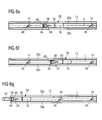
- FIGS. 6b to 6f illustrate various ways to position the air chamber housing 16 relative to the air supply pipe 12.
- the air chamber housing 16, as in the Figures 6b and 6c illustrated rotated 180 ° relative to the air supply pipe 12 to adjust the position of the first connection opening 38 of the connecting device 34 to the position of an intended for connection to the air chamber housing 16 air supply device 36.
- a displacement of the air chamber housing 16 parallel to the longitudinal axis L of the air supply pipe 12 is possible, whereby the air chamber housing 16, as in the FIGS. 6d and 6e shown, with an adjacent air outlet opening 14 of the air supply pipe can be associated.
- the air chamber housing 16 can also be displaced only so far in parallel to the longitudinal axis L of the air supply pipe that it still covers the same air outlet opening 14 of the air supply pipe, but still allows some adaptation to the position of an air supply 16 to be connected to the air chamber housing 16 (see FIGS. 6e and 6f ).
- the air chamber housing 16, as in FIG. 6g additionally provided with an extension adapter 42 which connects the second connection opening 40 of the connection device 34 with the air supply device 16.
- air outlet openings 14 of the air supply pipe 12 with corresponding, designed for example in the form of screw caps closure devices 46 are sealingly closed.
Landscapes
- Health & Medical Sciences (AREA)
- General Health & Medical Sciences (AREA)
- Pulmonology (AREA)
- Engineering & Computer Science (AREA)
- Aviation & Aerospace Engineering (AREA)
- Air-Conditioning For Vehicles (AREA)
- Duct Arrangements (AREA)
Abstract
Description
- Die Erfindung betrifft ein zur Montage in einer Flugzeugpassagierkabine vorgesehenes Belüftungssystem, insbesondere ein Individualbelüftungssystem sowie eine mit einem derartigen Belüftungssystem ausgestattete Flugzeugklimaanlage.
- Moderne Verkehrsflugzeuge sind üblicherweise mit einem Individualbelüftungssystem ausgerüstet, das die Passagiere in der Passagierkabine des Flugzeugs individuell mit von einer Flugzeugklimaanlage bereitgestellter Klimatisationsluft versorgt. Ein gängiges Individualbelüftungssystem umfasst ein Individualluftzufuhrrohr, das sich in der Flugzeugpassagierkabine in einem Bereich unterhalb von zur Aufnahme von Handgepäckstücken der Passagiere dienenden Gepäckfächern oder im Bereich einer Seitenwand der Passagierkabine im Wesentlichen parallel zu einer Längsachse der Flugzeugpassagierkabine erstreckt. Das Individualluftzufuhrrohr wird von Klimatisationsluft durchströmt, die dem Individualluftzufuhrrohr von einer Klimatisationslufterzeugungseinrichtung der Flugzeugklimaanlage zugeführt wird.
- Aus der
EP 0 607 602 A1 ist eine Anordnung bekannt, die eine Luftleitung sowie eine Passagierversorgungseinheit umfasst. Die Luftleitung besteht aus einem geradlinigen formsteifen Hohlprofil mit einem Längsschlitz, wobei der Längsschlitz durch eine Dichtlippe abgedichtet ist. Zur Entnahme der Luft ist ein in Längsrichtung der Luftleitung geführter Schlitten mit einem in einen Innenraum des Hohlprofils hineinragenden Entnahmestutzen vorgesehen. Der Schlitten weist eine Außenführung sowie eine Innenführung auf, die mit dem Entnahmestutzen fest verbunden und so in einem Abstand voneinander angeordnet sind, dass sie einen an die Dichtlippe angepassten Zwischenraum bilden. - Die
DE 10 2010 018 502 betrifft ein Versorgungssystem zur Versorgung von Passagieren an Bord eines Flugzeugs, das eine Versorgungsleitung sowie eine Mehrzahl von Versorgungsmodulen umfasst, die zur Versorgung der Passagiere mit einer Versorgungsöffnung der Versorgungsleitung verbindbar sind. Die Versorgungsmodule sind entlang der Versorgungsleitung relativ zueinander verschiebbar. Jedem Versorgungsmodul ist eine Blende zugeordnet, die entlang der Versorgungsleitung verschiebbar ist, um eine nicht zur Verbindung eines Versorgungsmoduls mit der Versorgungsleitung genutzte Versorgungsöffnung abzudecken. - Die Erfindung ist auf die Aufgabe gerichtet, ein einfach montier- und, bei Bedarf, einfach rekonfigurierbares Belüftungssystem für eine Flugzeugpassagierkabine bereitzustellen. Ferner ist die Erfindung auf die Aufgabe gerichtet, eine mit einem derartigen Belüftungssystem ausgestattete Flugzeugklimaanlage anzugeben.
- Diese Aufgabe wird durch ein Belüftungssystem mit den Merkmalen des Anspruchs 1 sowie eine Flugzeugklimaanlage mit den Merkmalen des Anspruchs 15 gelöst.
- Ein erfindungsgemäßes, zur Montage in einer Flugzeugpassagierkabine vorgesehenes Belüftungssystem umfasst ein Luftzufuhrrohr, das eine Mehrzahl von entlang seiner Längsachse verteilt angeordneten Luftauslassöffnungen aufweist. Das Luftzufuhrrohr ist vorzugsweise in Form eines starren Rohrs ausgeführt und kann beispielsweise aus einem extrudierten Kunststoffmaterial bestehen. Der Querschnitt des Luftzufuhrrohrs kann, je nach Bedarf, an die Einbauraumgegebenheiten in der Flugzeugpassagierkabine angepasst werden und beispielsweise rechteckig, rund oder oval sein. Vorzugsweise sind die Luftauslassöffnungen des Luftzufuhrrohrs hintereinander im Wesentlichen in einer Linie entlang der Längsachse des Luftzufuhrrohrs verteilt angeordnet. Falls erforderlich, ist jedoch auch eine versetzte Anordnung der Luftauslassöffnungen denkbar. Das Luftzufuhrrohr ist vorzugsweise mit einer Klimatisationslufterzeugungseinrichtung einer Flugzeugklimaanlage verbunden, so dass das Luftzufuhrrohr im Betrieb des erfindungsgemäßen Belüftungssystems von Klimatisationsluft durchströmt wird, die dem Luftzufuhrrohr von der Klimatisationslufterzeugungseinrichtung der Flugzeugklimaanlage zugeführt wird.
- Das erfindungsgemäße Belüftungssystem umfasst ferner ein Luftkammergehäuse, das entlang der Längsachse des Luftzufuhrrohrs an verschiedenen Positionen mit dem Luftzufuhrrohr verbindbar ist. Die Verbindung des Luftkammergehäuses mit dem Luftzufuhrrohr erfolgt derart, dass das Luftzufuhrrohr durchströmende Klimatisationsluft durch eine in dem Luftzufuhrrohr vorgesehene Luftauslassöffnung in das Luftkammergehäuse zuführbar ist. Das Luftkammergehäuse wird vorzugsweise derart an dem Luftzufuhrrohr befestigt, dass das Luftkammergehäuse mindestens eine Luftauslassöffnung des Luftzufuhrrohrs überdeckt. Grundsätzlich kann das Luftkammergehäuse eine beliebige Form haben. Vorzugsweise hat das Luftkammergehäuse jedoch eine langgestreckte Form, so dass das Luftkammergehäuse über eine längere Strecke entlang der Längsachse des Luftzufuhrrohrs versetzt werden kann, die in dem Luftzufuhrrohr ausgebildete Luftauslassöffnung aber immer noch überdeckt. Um das Gewicht des erfindungsgemäßen Belüftungssystems nicht unnötig zu erhöhen, ist die Längserstreckung des Luftkammergehäuses vorzugsweise jedoch geringer als der Abstand zwischen zwei zueinander benachbarten Luftauslassöffnungen des Luftzufuhrrohrs.
- Schließlich umfasst das erfindungsgemäße Belüftungssystem eine Verbindungseinrichtung, die dazu eingerichtet ist, das Luftkammergehäuse mit einer Luftzufuhrvorrichtung zur Zufuhr von Klimatisationsluft in die Flugzeugpassagierkabine zu verbinden. Die Luftzufuhrvorrichtung zur Zufuhr von Klimatisationsluft in die Flugzeugpassagierkabine kann beispielsweise eine individuell bedienbare Luftdusche eines Individualbelüftungssystems sein. Alternativ dazu kann es sich bei der Luftzufuhrvorrichtung jedoch auch um eine Luftzufuhrvorrichtung eines zentral gesteuerten Teilsystems des Kabinenbelüftungssystems handeln.
- Das erfindungsgemäße Belüftungssystem ermöglicht eine einfache und flexible Verbindung von an verschiedenen Positionen in der Flugzeugpassagierkabine angeordneten Luftzufuhrvorrichtungen zur Zufuhr von Klimatisationsluft in Flugzeugpassagierkabinen an das Luftzufuhrrohr durch entsprechendes Positionieren des Luftkammergehäuses entlang der Längsachse des Luftzufuhrrohrs. Auf die Bereitstellung unterschiedlich langer flexibler Schläuche, wie sie beispielsweise in herkömmlichen Individualbelüftungssystemen eingesetzt werden, kann daher bei dem erfindungsgemäßen Belüftungssystem verzichtet werden. Die Bereitstellung entsprechender Aufnahmen für die Schläuche ist ebenfalls nicht länger erforderlich. Schließlich erlaubt die flexible Positionierung des Luftkammergehäuses entlang der Längsachse des Luftzufuhrrohrs den Verzicht auf die Bereitstellung von Doppelluftauslässen an dem Luftzufuhrrohr und Doppellufteinlässen an der Zufuhrvorrichtung zur Zufuhr von Klimatisationsluft in die Flugzeugpassagierkabine. Das erfindungsgemäße Belüftungssystem zeichnet sich somit durch ein geringes Gewicht sowie eine einfache Montierbarkeit aus. Ferner ist das Belüftungssystem im Rahmen einer Rekonfigurierung der Flugzeugpassagierkabine mit geringem Aufwand rekonfigurierbar. Der Vorteil der einfachen Rekonfigurierbarkeit des Belüftungssystems kommt besonders zum Tragen, wenn das erfindungsgemäße Belüftungssystem als Individualbelüftungssystem ausgeführt ist. Grundsätzlich kann das erfindungsgemäße Belüftungssystem jedoch auch in Form eines zentral gesteuerten Teilsystems des Passagierkabinenbelüftungssystems des Flugzeugs ausgeführt sein.
- Das Luftkammergehäuse umfasst vorzugsweise einen von einem Seitenwandbereich des Luftkammergehäuses begrenzten offenen Anschlussbereich, der dazu eingerichtet ist, die Zufuhr von aus einer Luftauslassöffnung des Luftzufuhrrohrs austretender Klimatisationsluft in das Luftkammergehäuse zu ermöglichen. Beispielsweise kann das Luftkammergehäuse einen in seinem Anschlussbereich offenen halbrunden oder halbovalen Querschnitt aufweisen. Es versteht sich, dass das Luftkammergehäuse jedoch auch einen eckigen Querschnitt haben kann. Wenn das Luftkammergehäuse mit dem Luftzufuhrrohr verbunden ist, grenzt das Luftkammergehäuse im Bereich seines offenen Anschlussbereichs an eine Außenfläche des Luftzufuhrrohrs, so dass aus einer Luftauslassöffnung des Luftzufuhrrohrs austretende Klimatisationssluft durch den offenen Anschlussbereich des Luftkammergehäuses in das Luftkammergehäuse einströmen kann.
- Vorzugsweise umfasst das Luftkammergehäuse ein Dichtelement, das sich entlang eines dem Luftzufuhrrohr zugewandten Rands des Seitenwandbereichs des Luftkammergehäuses erstreckt. Insbesondere handelt es sich bei dem Dichtelement um ein umlaufendes Dichtelement, das entlang des gesamten dem Luftzufuhrrohr zugewandten Rands des Seitenwandbereichs des Luftkammergehäuses eine Abdichtung des Luftkammergehäuses gegenüber der Umgebung ermöglicht. Im mit dem Luftzufuhrrohr verbundenen Zustand wirkt das Dichtelement vorzugsweise mit einer Außenfläche des Luftzufuhrrohrs zusammen.
- In einer bevorzugten Ausführungsform des erfindungsgemäßen Belüftungssystems umfasst das Luftzufuhrrohr eine sich entlang seiner Längsachse erstreckende Führungseinrichtung, die dazu eingerichtet ist, eine geführte Verschiebung des Luftkammergehäuses entlang der Längsachse des Luftzufuhrrohrs zu ermöglichen. Eine an dem Luftzufuhrrohr vorgesehene Führungseinrichtung ermöglicht eine besonders einfache Montage und/oder Rekonfiguration des erfindungsgemäßen Belüftungssystems. Die Führungseinrichtung kann beispielsweise zwei sich entlang der Längsachse des Luftzufuhrrohrs und im Wesentlichen parallel zueinander erstreckende Führungsschienen umfassen. Die Führungsschienen können von einer Außenfläche des Luftzufuhrrohrs in Richtung des Luftkammergehäuses ragen und mit Außenflächen zweier einander gegenüberliegender Seitenwandbereichsabschnitte des Luftkammergehäuses zusammenwirken, um eine geführte Verschiebung des Luftkammergehäuses entlang der Längsachse des Luftzufuhrrohrs zu ermöglichen.
- Vorzugsweise umfasst das erfindungsgemäße Belüftungssystem ferner eine Verriegelungsvorrichtung zur Verriegelung des Luftkammergehäuses in einer gewünschten Position entlang der Längsachse des Luftzufuhrrohrs. Die Verriegelungsvorrichtung sorgt dafür, das Luftkammergehäuse sicher in einer gewünschten Position entlang der Längsachse des Luftzufuhrrohrs zu fixieren.
- Vorzugsweise umfasst die Verriegelungsvorrichtung ein Verriegelungselement, das zwischen einer Entriegelungsstellung und einer Verriegelungsstellung bewegbar mit dem Luftkammergehäuse verbunden ist und in seiner Verriegelungsstellung mit einer an dem Luftzufuhrrohr vorgesehenen Aufnahmevorrichtung in Eingriff bringbar ist. Zur Positionierung des Luftkammergehäuses relativ zu dem Luftzufuhrrohr kann das Verriegelungselement dann in seiner Entriegelungsstellung gebracht werden, wodurch eine ungehinderte Bewegung des Luftkammergehäuses entlang der Längsachse des Luftzufuhrrohrs, aber auch ein vollständiges Lösen des Luftkammergehäuses von dem Luftzufuhrrohr möglich ist. Wenn das Luftkammergehäuse in der gewünschten Position entlang der Längsachse des Luftzufuhrrohrs angeordnet ist, kann das Verriegelungselement in seine Verriegelungsstellung bewegt werden, um das Luftkammergehäuse an dem Luftzufuhrrohr zu fixieren.
- Die an dem Lufzufuhrrohr vorgesehene Aufnahmevorrichtung umfasst vorzugsweise mindestens eine Aufnahmenut. Die Aufnahmenut kann an der sich entlang der Längsachse des Luftzufuhrrohrs erstreckenden Führungseinrichtung ausgebildet sein. Bei einer besonders bevorzugten Ausführungsform des erfindungsgemäßen Belüftungssystems sind zwei sich entlang der Längsachse des Luftzufuhrrohrs und im Wesentlichen parallel zueinander erstreckende Führungsschienen der Führungseinrichtung jeweils mit einer Aufnahmenut versehen. Das Verriegelungselement kann dann in Form eines drehbar mit dem Luftkammergehäuse verbundenen Verriegelungselement ausgeführt sein. In der Entriegelungsstellung des Verriegelungselements befindet sich das Verriegelungselement außer Eingriff mit den Aufnahmenuten der Aufnahmevorrichtung. Wenn sich das Verriegelungselement dagegen in seiner Verriegelungsstellung befindet, greifen Randabschnitte des Verriegelungselements in die Aufnahmenuten der Aufnahmevorrichtung ein.
- Vorzugsweise ist das Verriegelungselement der Verriegelungsvorrichtung dazu eingerichtet, in seiner Verriegelungsstellung eine Kraft auf das Luftkammergehäuse aufzubringen, die das Luftkammergehäuse gegen das Luftzufuhrrohr drückt. Das Verriegelungselement erfüllt dann nicht nur die Funktion, das Luftkammergehäuse in einer gewünschten Position an dem Luftzufuhrrohr zu fixieren, sondern drückt auch das Dichtelement des Luftkammergehäuses gegen die Außenfläche des Luftzufuhrrohrs und trägt somit dazu bei, dass das Luftkammergehäuse abdichtend mit dem Luftzufuhrrohr verbunden wird.
- Das Verriegelungselement ist vorzugsweise in Form einer Verriegelungsklammer ausgebildet, die das Luftkammergehäuse in ihrer Verriegelungsstellung zumindest abschnittsweise umspannt. Ein derart ausgeführtes Verriegelungselement ist einfach konstruiert, erlaubt aber dennoch nicht nur eine sichere Fixierung des Luftkammergehäuses an dem Luftzufuhrrohr, sondern ermöglicht es auch, eine das Luftkammergehäuse gegen das Luftzufuhrrohr drückende Kraft auf das Luftkammergehäuse aufzubringen.
- Nicht mit einem Luftkammergehäuse verbundene, bzw. nicht von einem Luftkammergehäuse überdeckte Luftauslassöffnungen des Luftzufuhrrohrs sind bei dem erfindungsgemäßen Belüftungssystem vorzugsweise mittels entsprechender Verschlussvorrichtungen abdichtend verschlossen. Dadurch wird verhindert, dass das Luftzufuhrrohr durchströmende Klimatisationsluft in unerwünschter Weise aus dem Luftzufuhrrohr austritt. Die Verschlussvorrichtungen können beispielsweise in Form von Schraubverschlüssen, Stopfen oder dergleichen ausgeführt sein.
- Die Verbindungseinrichtung des erfindungsgemäßen Belüftungssystems weist vorzugsweise eine Mehrzahl von Verbindungsöffnungen zur Verbindung des Luftkammergehäuses mit einer Luftzufuhrvorrichtung zur Zufuhr von Klimasitationsluft in die Flugzeugpassagierkabine auf. Durch die Ausgestaltung der Verbindungseinrichtung mit mehreren Verbindungsöffnungen wird die Flexibilität des Belüftungssystems weiter erhöht.
- Beispielsweise kann eine erste Verbindungsöffnung der Verbindungseinrichtung so angeordnet sein, dass sie im Wesentlichen senkrecht zur Längsachse des Luftzufuhrrohrs von Klimasitationsluft durchströmbar ist. Eine zweite Verbindungsöffnung der Verbindungseinrichtung kann dagegen so angeordnet sein, dass sie im Wesentlichen parallel zur Längsachse des Luftzufuhrrohrs von Klimatisationsluft durchströmbar ist.
- Eine nicht mit einer Luftzufuhrvorrichtung zur Zufuhr von Klimatisationsluft in die Flugzeugpassagierkabine verbundene Verbindungsöffnung der Verbindungseinrichtung ist vorzugsweise mittels einer entsprechenden Verschlussvorrichtung abdichtend verschlossen. Dadurch wird verhindert, dass in unerwünschter Weise Klimatisationsluft aus dem Luftkammergehäuse austritt. Als Verschlussvorrichtung kann ein Schraubverschluss oder ein Stopfen verwendet werden.
- Grundsätzlich ist es möglich, alle Verbindungsöffnungen der Verbindungseinrichtung mit einer Zufuhrvorrichtung oder mehreren Zufuhrvorrichtung zur Zufuhr von Klimatisationsluft in die Flugzeugpassagierkabine zu verbinden. Vorzugsweise wird jedoch lediglich eine Verbindungsöffnung der Verbindungseinrichtung mit einer Luftzufuhrvorrichtung zur Zufuhr von Klimatisationsluft in die Flugzeugpassagierkabine verbunden. In Abhängigkeit der Position der Luftzufuhrvorrichtung relativ zu dem Luftkammergehäuse kann die günstiger angeordnete Verbindungsöffnung der Verbindungseinrichtung zur Verbindung des Luftkammergehäuses mit der Luftzufuhrvorrichtung verwendet werden. Beispielsweise kann eine im Wesentlichen senkrecht zur Längsachse des Luftzufuhrrohrs von Klimatisationsluft durchströmbare erste Verbindungsöffnung der Verbindungseinrichtung unmittelbar mit der Luftzufuhrvorrichtung verbunden, eine im Wesentlichen parallel zur Längsachse des Luftzufuhrrohrs von Klimatisationsluft durchströmbare zweite Verbindungsöffnung der Verbindungseinrichtung dagegen mittels einer entsprechenden Verschlussvorrichtung abgedichtet werden. Eine derartige Konfiguration des erfindungsgemäßen Belüftungssystems ist insbesondere dann sinnvoll, wenn die Luftzufuhrvorrichtung so positioniert ist und das Luftkammergehäuse derart relativ zu dem Luftzufuhrrohr angeordnet werden kann, dass eine unmittelbare Verbindung der Verbindungseinrichtung mit der Luftzufuhrvorrichtung möglich ist.
- Falls erforderlich, kann die Verbindungseinrichtung jedoch auch einen Verlängerungsadapter umfassen, der eine Verbindungsöffnung der Verbindungseinrichtung mit einer Luftzufuhrvorrichtung zur Zufuhr von Klimatisationsluft in die Flugzeugpassagierkabine verbindet. Vorzugsweise ist ein derartiger Verlängerungsadapter mit der zweiten Verbindungsöffnung der Verbindungseinrichtung verbunden, die im Wesentlichen parallel zur Längsachse des Luftzufuhrrohrs von Klimatisationsluft durchströmbar ist.
- Eine erfindungsgemäße Flugzeugklimaanlage umfasst ein oben beschriebenes Belüftungssystem.
- Eine bevorzugte Ausführungsform der Erfindung wird nun anhand der beigefügten schematischen Zeichnungen näher erläutert, von denen
- Figur 1
- eine Querschnittsdarstellung eines in Form eines Individualbelüftungssystems ausgebildeten Flugzeugpassagierkabinenbelüftungssystems zeigt,
- Figuren 2a bis 2c
- verschiedene Ansichten eines Luftkammergehäuses des Belüftungssystems zeigen,
- Figuren 3a bis 3b
- verschiedene Ansichten eines mit einem Verlängerungsadapter ausgestatteten Luftkammergehäuses des Belüftungssystems zeigen,
- Figur 4
- zwei jeweils mit einer Zufuhrvorrichtung zur Zufuhr von Klimatisationsluft in eine Flugzeugpassagierkabine verbundene Luftkammergehäuse gemäß den
Figuren 2a bis 2c zeigt, - Figur 5
- zwei jeweils mit einer Luftzufuhrvorrichtung zur Zufuhr von Klimatisationsluft in eine Flugzeugpassagierkabine verbundene Luftkammergehäuse gemäß den
Figuren 3a bis 3b zeigt, und - Figuren 6a bis 6g
- Seitenansichten eines Luftzufuhrrohrs (
Figur 6a ) sowie eines Luftzufuhrrohrs, mit dem ein Luftkammergehäuse verbunden ist, (Figuren 6b bis 6g ) zeigen. - Ein in den Figuren veranschaulichtes Belüftungssystem 10 zur Zufuhr von Klimatisationsluft in eine Flugzeugpassagierkabine ist als Individualbelüftungssystem ausgeführt, das dazu dient, die Passagiere in der Passagierkabine des Flugzeugs individuell mit von einer Flugzeugklimaanlage bereitgestellter Klimatisationsluft zu versorgen. Das Belüftungssystem 10 umfasst ein Luftzufuhrrohr 12, das mit einer nicht veranschaulichten Klimatisationslufterzeugungseinrichtung der Flugzeugklimaanlage verbunden ist. Im Betrieb des Belüftungssystems 10 wird das Luftzufuhrrohr 12 von Klimatisationsluft durchströmt, die dem Luftzufuhrrohr 12 von der Klimatisationslufterzeugungseinrichtung der Flugzeugklimaanlage zugeführt wird. Wie in
Figur 1 zu erkennen ist, weist das Luftzufuhrrohr 12 in dem in den Figuren veranschaulichten Ausführungsbeispiel einen ovalen Querschnitt auf. DieFiguren 6a bis 6g veranschaulichen, dass das Luftzufuhrrohr 12 mit einer Mehrzahl von Luftauslassöffnungen 14 versehen ist, die entlang einer Längsachse L des Luftzufuhrrohrs verteilt angeordnet sind. In dem gezeigten Ausführungsbeispiel eines Belüftungssystems 10 sind die Luftauslassöffnungen 14 in gleichbleibenden Abständen voneinander im Wesentlichen in einer Linie positioniert. Bei Bedarf kann das Luftzufuhrrohr 12 jedoch auch mit versetzt zueinander angeordneten und/oder in unterschiedlichen Abständen voneinander positionierten Luftauslassöffnungen 14 versehen sein. - Das Belüftungssystem 10 umfasst ferner ein Luftkammergehäuse 16. Wie am Besten in den
Figuren 6b bis 6g zu erkennen ist, ist das Luftkammergehäuse 16 entlang der Längsachse L des Luftzufuhrrohrs 12 an verschiedenen Positionen mit dem Luftzufuhrrohr verbindbar. In seinem mit dem Luftzufuhrrohr 12 verbundenen Zustand überdeckt das Luftkammergehäuse 16 eine in dem Luftzufuhrrohr 12 ausgebildete Luftauslassöffnung 14, so dass das Luftzufuhrrohr 12 durchströmende Klimatisationsluft durch die in dem Luftzufuhrrohr 12 vorgesehene und von dem Luftkammergehäuse 16 überdeckte Luftauslassöffnung 14 in das Luftkammergehäuse 16 zuführbar ist. - Wie am Besten in den
Figuren 2a bis 2c und 3a bis 3b zu erkennen ist, umfasst das Luftkammergehäuse 16 einen Seitenwandbereich 18, der einen offenen Anschlussbereich 20 des Luftkammergehäuses 16 begrenzt. Im mit dem Luftzufuhrrohr 12 verbundenen Zustand des Luftkammergehäuses 16 kann durch den offenen Anschlussbereich 20 aus der von dem Luftkammergehäuse 16 überdeckten Luftauslassöffnung 14 des Luftzufuhrrohrs 12 austretende Klimatisationsluft in das Luftkammergehäuse 16 zugeführt werden. Entlang eines Rands 22 seines Seitenwandbereichs 18 ist das Luftkammergehäuse 16 mit einem umlaufenden Dichtelement 24 versehen. Im mit dem Luftzufuhrrohr 12 verbundenen Zustand des Luftkammergehäuses 16 liegt das Dichtelement 24 an einer Außenfläche des Luftzufuhrrohrs 12 an und sorgt somit für eine Abdichtung des Luftkammergehäuses 16 gegenüber der Umgebung. Das Luftkammergehäuse 16 weist eine langgestreckte Form auf. Die Längserstreckung des Luftkammergehäuses 16 ist jedoch geringer als der Abstand zwischen zwei zueinander benachbarten Luftauslassöffnungen 14 des Luftzufuhrrohrs 12. - Das Luftzufuhrrohr 12 ist mit einer Führungseinrichtung 26 versehen, die dazu eingerichtet ist, eine geführte Verschiebung des Luftkammergehäuses 16 entlang der Längsachse L des Luftzufuhrrohrs 12 zu ermöglichen. Die Führungseinrichtung 26 umfasst zwei sich entlang der Längsachse L des Luftzufuhrrohrs 12 und im Wesentlichen parallel zueinander erstreckende Führungsschienen 26a, 26b, die mit zwei einander gegenüberliegenden Außenflächenabschnitten des Seitenwandbereichs 18 des Luftkammergehäuses 16 zusammenwirken. Die Führungseinrichtung 26 ermöglicht eine geführte Verschiebung des Luftkammergehäuses 16 entlang der Längsachse L des Luftzufuhrrohrs 12.
- Zur Fixierung des Luftkammergehäuses 16 in einer gewünschten Position an dem Luftzufuhrrohr 12 ist eine Verriegelungsvorrichtung 28 vorhanden. Die Verriegelungsvorrichtung 28 umfasst ein in Form einer Verriegelungsklammer ausgebildetes Verriegelungselement 30, das zwischen einer Entriegelungsstellung und einer Verriegelungsstellung drehbar mit dem Luftkammergehäuse 16 verbunden ist. In seiner in den Figuren veranschaulichten Verriegelungsstellung befindet sich das Verriegelungselement 30 in Eingriff mit einer an dem Luftzufuhrrohr 12 vorgesehenen Aufnahmevorrichtung 32. Die Aufnahmevorrichtung 32 umfasst zwei einander gegenüberliegende Aufnahmennuten 32a, 32b, die an den Führungsschienen 26a, 26b ausgebildet sind (siehe
Figur 1 ). Wenn sich das Verriegelungselement 30 in seiner Verriegelungsstellung befindet, greifen Randabschnitte des Verriegelungselements 30 in die Aufnahmenuten 32a, 32b ein, wodurch das Luftkammergehäuse 16 in seiner Position relativ zu dem Luftzufuhrrohr 12 fixiert wird. Ferner bringt das in Form einer das Luftkammergehäuse 16 abschnittsweise überspannenden Verriegelungsklammer ausgebildete Verriegelungselemente 30 in seiner Verriegelungsstellung eine Kraft auf das Luftkammergehäuse 16 auf, die das Luftkammergehäuse 16 gegen das Luftzufuhrrohr 12 drückt. Dadurch wird die Dichtwirkung des Dichtelements 24 verbessert. - Schließlich umfasst das Belüftungssystem 10 eine Verbindungseinrichtung 34, die dazu dient, das Luftkammergehäuse 16 mit einer in den
Figuren 4 und 5 gezeigten Luftzufuhrvorrichtung 36 zur Zufuhr von Klimatisationsluft in die Flugzeugpassagierkabine zu verbinden. In dem hier gezeigten Ausführungsbeispiel eines Belüftungssystems 10 ist die Luftzufuhrvorrichtung 36 in Form einer individuell bedienbaren Luftdusche ausgeführt. Wie am Besten in denFiguren 2a bis 2c zu erkennen ist, umfasst die Verbindungseinrichtung 34 eine erste Verbindungsöffnung 38, die so positioniert ist, dass sie im Wesentlichen senkrecht zur Längsachse L des Luftzufuhrrohrs 12 von Klimatisationsluft durchströmbar ist. Eine zweite Verbindungsöffnung 40 der Verbindungseinrichtung 34 ist dagegen so angeordnet, dass sie im Wesentlichen parallel zur Längsachse L des Luftzufuhrrohrs 12 von Klimatisationsluft durchströmbar ist. Die erste Verbindungsöffnung 38 dient dazu, das Luftkammergehäuse, wie inFigur 4 gezeigt, unmittelbar mit einer Luftzufuhrvorrichtung 36 zur Zufuhr von Klimatisationsluft in die Flugzeugpassagierkabine zu verbinden. Die zweite Verbindungsöffnung 40 kann dagegen, wie inFigur 5 gezeigt, dazu genutzt werden, einen Verlängerungsadapter 42 zwischen das Luftkammergehäuse 16 und die Luftzufuhrvorrichtung 36 zu schalten. Die nicht mit der Luftzufuhrvorrichtung 36 verbundene Verbindungseinrichtung 38, 40 ist jeweils mit einer Verschlussvorrichtung 44, die beispielsweise in Form eines Schraubverschlusses ausgeführt sein kann, abdichtend verschlossen. - Die
Figuren 6b bis 6f veranschaulichen verschiedene Möglichkeiten, das Luftkammergehäuse 16 relativ zu dem Luftzufuhrrohr 12 zu positionieren. Beispielsweise kann das Luftkammergehäuse 16, wie in denFiguren 6b und 6c veranschaulicht, um 180° relativ zu dem Luftzufuhrrohr 12 gedreht werden, um die Position der ersten Verbindungsöffnung 38 der Verbindungseinrichtung 34 an die Position einer zur Verbindung mit dem Luftkammergehäuse 16 vorgesehenen Luftzufuhrvorrichtung 36 anzupassen. Ferner ist eine Verschiebung des Luftkammergehäuses 16 parallel zur Längsachse L des Luftzufuhrrohrs 12 möglich, wodurch das Luftkammergehäuse 16, wie in denFiguren 6d und6e gezeigt, mit einer benachbarten Luftauslassöffnung 14 des Luftzufuhrrohrs in Verbindung gebracht werden kann. Alternativ dazu kann das Luftkammergehäuse 16 jedoch auch lediglich soweit parallel zur Längsachse L des Luftzufuhrrohrs verschoben werden, dass es noch dieselbe Luftauslassöffnung 14 des Luftzufuhrrohrs überdeckt, aber dennoch eine gewisse Anpassung an die Position einer mit dem Luftkammergehäuse 16 zu verbindenden Luftzufuhrvorrichtung 16 erlaubt (sieheFiguren 6e und 6f ). Schließlich kann das Luftkammergehäuse 16, wie inFigur 6g veranschaulicht, zusätzlich mit einem Verlängerungsadapter 42 versehen werden, der die zweite Verbindungsöffnung 40 der Verbindungseinrichtung 34 mit der Luftzufuhrvorrichtung 16 verbindet. - Um einen unerwünschten Austritt von Klimatisationsluft aus dem Luftzufuhrrohr 12 zu verhindern, sind bei dem Belüftungssystem 10 nicht von dem Luftkammergehäuse 16 überdeckte Luftauslassöffnungen 14 des Luftzufuhrrohrs 12 mit entsprechenden, beispielsweise in Form von Schraubverschlüssen ausgeführten Verschlussvorrichtungen 46 abdichtend verschlossen.
Claims (15)
- Belüftungssystem (10) zur Montage in einer Flugzeugpassagierkabine, welches umfasst:- ein Luftzufuhrrohr (12), das eine Mehrzahl von entlang seiner Längsache (L) verteilt angeordneten Luftauslassöffnungen (14) aufweist,- ein Luftkammergehäuse (16), das entlang der Längsache (L) des Luftzufuhrrohrs (12) an verschiedenen Positionen mit dem Luftzufuhrrohr (12) verbindbar ist, so dass das Luftzufuhrrohr (12) durchströmende Klimatisationsluft durch eine in dem Luftzufuhrrohr (12) vorgesehene Luftauslassöffnung (14) in das Luftkammergehäuse (16) zuführbar ist, und- eine Verbindungseinrichtung (34), die dazu eingerichtet ist, das Luftkammergehäuse (16) mit einer Luftzufuhrvorrichtung (36) zur Zufuhr von Klimatisationsluft in die Flugzeugpassagierkabine zu verbinden.
- Belüftungssystem nach Anspruch 1,
dadurch gekennzeichnet, dass das Luftkammergehäuse (16) einen von einem Seitenwandbereich (18) des Luftkammergehäuses (16) begrenzten offenen Anschlussbereich (20) umfasst, der dazu eingerichtet ist, die Zufuhr von aus einer Luftauslassöffnung (14) des Luftzufuhrrohrs (12) austretender Klimatisationsluft in das Luftkammergehäuse (16) zu ermöglichen. - Belüftungssystem nach Anspruch 1 oder 2,
dadurch gekennzeichnet, dass das Luftkammergehäuse (16) ein Dichtelement (24) umfasst, das sich entlang eines dem Luftzufuhrrohr (12) zugewandten Rands (22) des Seitenwandbereichs (18) des Luftkammergehäuses (16) erstreckt. - Belüftungssystem nach einem der Ansprüche 1 bis 3,
dadurch gekennzeichnet, dass das Luftzufuhrrohr (12) eine sich entlang seiner Längsachse (L) erstreckende Führungseinrichtung (26) umfasst, die dazu eingerichtet ist, eine geführte Verschiebung des Luftkammergehäuses (16) entlang der Längsache (L) des Luftzufuhrrohrs (12) zu ermöglichen. - Belüftungssystem nach einem der Ansprüche 1 bis 4,
gekennzeichnet durch eine Verriegelungsvorrichtung (28) zur Verriegelung des Luftkammergehäuses (16) in einer gewünschten Position entlang der Längsache (L) des Luftzufuhrrohrs (12). - Belüftungssystem nach Anspruch 5,
dadurch gekennzeichnet, dass die Verriegelungsvorrichtung (28) ein Verriegelungselement (30) umfasst, das zwischen einer Entriegelungsstellung und einer Verriegelungsstellung bewegbar mit dem Luftkammergehäuse (16) verbunden ist und in seiner Verriegelungsstellung mit einer an dem Luftzufuhrrohr (12) vorgesehenen Aufnahmevorrichtung (32) in Eingriff bringbar ist. - Belüftungssystem nach Anspruch 6,
dadurch gekennzeichnet, dass die an dem Luftzufuhrrohr (12) vorgesehenen Aufnahmevorrichtung (32) mindestens eine Aufnahmenut (32a, 32b) umfasst, die an der sich entlang der Längsachse (L) des Luftzufuhrrohrs (12) erstreckenden Führungseinrichtung (26) ausgebildet ist. - Belüftungssystem nach Anspruch 6 oder 7,
dadurch gekennzeichnet, dass das Verriegelungselement (30) dazu eingerichtet ist, in seiner Verriegelungsstellung eine Kraft auf das Luftkammergehäuse (16) aufzubringen, die das Luftkammergehäuse (16) gegen das Luftzufuhrrohr (12) drückt. - Belüftungssystem nach einem der Ansprüche 6 bis 8,
dadurch gekennzeichnet, dass das Verriegelungselement (30) in seiner Verriegelungsstellung das Luftkammergehäuse (16) zumindest abschnittsweise umspannt. - Belüftungssystem nach einem der Ansprüche 1 bis 9,
dadurch gekennzeichnet, dass nicht von einem Luftkammergehäuse (16) überdeckte Luftauslassöffnungen (14) des Luftzufuhrrohrs (12) mittels entsprechender Verschlussvorrichtungen (46) abdichtend verschlossen sind. - Belüftungssystem nach einem der Ansprüche 1 bis 10,
dadurch gekennzeichnet, dass die Verbindungseinrichtung (34) eine Mehrzahl von Verbindungsöffnungen (38, 40) zur Verbindung des Luftkammergehäuses (16) mit einer Luftzufuhrvorrichtung (36) zur Zufuhr von Klimatisationsluft in die Flugzeugpassagierkabine ausweist. - Belüftungssystem nach Anspruch 11,
dadurch gekennzeichnet, dass eine erste Verbindungsöffnung (38) der Verbindungseinrichtung (34) so angeordnet ist, dass sie im Wesentlichen senkrecht zur Längsachse (L) des Luftzufuhrrohrs (12) von Klimatisationsluft durchströmbar ist, und dass eine zweite Verbindungsöffnung (40) der Verbindungseinrichtung (34) so angeordnet ist, dass sie im Wesentlichen parallel zur Längsachse (L) des Luftzufuhrrohrs (12) von Klimatisationsluft durchströmbar ist. - Belüftungssystem nach Anspruch 12,
dadurch gekennzeichnet, dass eine nicht mit einer Luftzufuhrvorrichtung (36) zur Zufuhr von Klimatisationsluft in die Flugzeugpassagierkabine verbundene Verbindungsöffnung (38, 40) der Verbindungseinrichtung (34) mittels einer entsprechenden Verschlussvorrichtung (44) abdichtend verschlossen ist. - Belüftungssystem nach einem der Ansprüche 1 bis 13,
dadurch gekennzeichnet, dass die Verbindungseinrichtung (34) einen Verlängerungsadapter (42) umfasst, der insbesondere mit der zweiten Verbindungsöffnung (40) der Verbindungseinrichtung (34) verbunden ist. - Flugzeugklimaanlage,
gekennzeichnet durch ein Belüftungssystem (10) nach einem der Ansprüche 1 bis 14.
Applications Claiming Priority (2)
| Application Number | Priority Date | Filing Date | Title |
|---|---|---|---|
| US41599610P | 2010-11-22 | 2010-11-22 | |
| DE102010052157A DE102010052157A1 (de) | 2010-11-22 | 2010-11-22 | Belüftungssystem und Flugzeugklimaanlage |
Publications (2)
| Publication Number | Publication Date |
|---|---|
| EP2455284A2 true EP2455284A2 (de) | 2012-05-23 |
| EP2455284A3 EP2455284A3 (de) | 2017-09-27 |
Family
ID=45062773
Family Applications (1)
| Application Number | Title | Priority Date | Filing Date |
|---|---|---|---|
| EP11009072.7A Withdrawn EP2455284A3 (de) | 2010-11-22 | 2011-11-15 | Belüftungssystem und Flugzeugklimaanlage |
Country Status (3)
| Country | Link |
|---|---|
| US (1) | US9656754B2 (de) |
| EP (1) | EP2455284A3 (de) |
| DE (1) | DE102010052157A1 (de) |
Cited By (1)
| Publication number | Priority date | Publication date | Assignee | Title |
|---|---|---|---|---|
| CZ307411B6 (cs) * | 2017-06-07 | 2018-08-01 | Příhoda S.R.O. | Vzduchotechnická vyústka pro vozidla a vozidlo se vzduchotechnickou vyústkou |
Families Citing this family (6)
| Publication number | Priority date | Publication date | Assignee | Title |
|---|---|---|---|---|
| US20140014436A1 (en) * | 2012-07-12 | 2014-01-16 | B/E Aerospace, Inc. | Noise-Reducing Air Inlet Grille for an Appliance |
| DE102012017349A1 (de) | 2012-08-31 | 2014-03-06 | Airbus Operations Gmbh | Luftübertragungssystem für flexible Passagierversorgungseinheiten |
| EP2876049B1 (de) * | 2013-11-21 | 2016-04-06 | Airbus Operations GmbH | Luftübertragungssystem für flexible Insassenversorgungseinheiten |
| CN111140980B (zh) * | 2019-12-25 | 2021-10-22 | 佛山市高明区安承升降装备研究院 | 一种主动送风的电梯系统 |
| US20210387737A1 (en) * | 2020-06-10 | 2021-12-16 | Walter Dorwin Teague Associates, Inc. | Passenger air shield |
| EP4471311A1 (de) * | 2023-05-31 | 2024-12-04 | Airbus Operations GmbH | Individueller luftzufuhrkanal und individuelle luftzufuhranordnung |
Citations (2)
| Publication number | Priority date | Publication date | Assignee | Title |
|---|---|---|---|---|
| EP0607602A1 (de) | 1993-01-22 | 1994-07-27 | DaimlerChrysler Aerospace Airbus Gesellschaft mit beschränkter Haftung | Anordnung, bestehend aus einer Luftleitung und einer Versorgungseinheit |
| DE102010018502A1 (de) | 2010-04-28 | 2011-11-03 | Airbus Operations Gmbh | Versorgungssystem zur Versorgung von Passagieren in einem Passagierraum eines Fahrzeugs |
Family Cites Families (14)
| Publication number | Priority date | Publication date | Assignee | Title |
|---|---|---|---|---|
| US3330506A (en) * | 1965-07-12 | 1967-07-11 | Lockheed Aircraft Corp | Adjustable passenger utility carrier |
| CA2355773A1 (en) * | 1998-12-16 | 2000-06-22 | Warren H. Anderson | Driver ventilation for delivery truck |
| US6857955B1 (en) * | 2003-06-04 | 2005-02-22 | Steven M Held | Ventilation extension kit |
| US20060130997A1 (en) * | 2004-12-22 | 2006-06-22 | Valeo Climate Control Corp. | Vehicle heating, cooling and drying conditioner for apparel |
| US8475245B2 (en) * | 2006-02-03 | 2013-07-02 | Toyota Motor Engineering & Manufacturing North America, Inc. | Vehicle air duct including strength rib |
| DE102006056516A1 (de) * | 2006-11-29 | 2008-06-05 | Isel Automation Gmbh & Co. Kg | Lineareinheit |
| DE102007014406B3 (de) * | 2007-03-26 | 2008-04-24 | Airbus Deutschland Gmbh | Versorgungskanal mit einem Luftverteilungssystem für Fahrzeuge, Flugzeug mit einem solchen Versorgungskanal und Verfahren zum Ausbilden eines Versorgungskanals |
| DE102007019539B4 (de) * | 2007-04-25 | 2012-12-13 | Airbus Operations Gmbh | Luftzufuhrvorrichtung für die Klimatisierung von Passagierräumen in Flugzeugen |
| DE102007040203A1 (de) * | 2007-08-25 | 2009-02-26 | Daimler Ag | Vorrichtung zur Belüftung eines Kraftfahrzeugs |
| DE102008026093B4 (de) * | 2008-05-30 | 2014-02-13 | Airbus Operations Gmbh | System und Verfahren zur Ventilation einer Flugzeugkabine |
| DE102008058271A1 (de) * | 2008-11-20 | 2010-05-27 | Airbus Deutschland Gmbh | Versorgungseinheit für flexible Versorgungskanäle |
| DE102010008626A1 (de) * | 2010-02-19 | 2011-08-25 | Airbus Operations GmbH, 21129 | Zuluftversorgung für Passagiere in Flugzeugen |
| DE102010012882B3 (de) * | 2010-03-26 | 2011-07-28 | Airbus Operations GmbH, 21129 | System zur Zuführung von Individualluft |
| DE102010018569A1 (de) * | 2010-04-28 | 2011-11-03 | Airbus Operations Gmbh | Trägerstruktur zum Einsatz in einer Luftzufuhranordnung sowie Versorgungssystem mit einer solchen Trägerstruktur und Verfahren zur Konfiguration |
-
2010
- 2010-11-22 DE DE102010052157A patent/DE102010052157A1/de not_active Withdrawn
-
2011
- 2011-11-15 EP EP11009072.7A patent/EP2455284A3/de not_active Withdrawn
- 2011-11-22 US US13/302,719 patent/US9656754B2/en not_active Expired - Fee Related
Patent Citations (2)
| Publication number | Priority date | Publication date | Assignee | Title |
|---|---|---|---|---|
| EP0607602A1 (de) | 1993-01-22 | 1994-07-27 | DaimlerChrysler Aerospace Airbus Gesellschaft mit beschränkter Haftung | Anordnung, bestehend aus einer Luftleitung und einer Versorgungseinheit |
| DE102010018502A1 (de) | 2010-04-28 | 2011-11-03 | Airbus Operations Gmbh | Versorgungssystem zur Versorgung von Passagieren in einem Passagierraum eines Fahrzeugs |
Cited By (1)
| Publication number | Priority date | Publication date | Assignee | Title |
|---|---|---|---|---|
| CZ307411B6 (cs) * | 2017-06-07 | 2018-08-01 | Příhoda S.R.O. | Vzduchotechnická vyústka pro vozidla a vozidlo se vzduchotechnickou vyústkou |
Also Published As
| Publication number | Publication date |
|---|---|
| US9656754B2 (en) | 2017-05-23 |
| US20120129438A1 (en) | 2012-05-24 |
| EP2455284A3 (de) | 2017-09-27 |
| DE102010052157A1 (de) | 2012-05-24 |
Similar Documents
| Publication | Publication Date | Title |
|---|---|---|
| DE102007019539B4 (de) | Luftzufuhrvorrichtung für die Klimatisierung von Passagierräumen in Flugzeugen | |
| DE102010052157A1 (de) | Belüftungssystem und Flugzeugklimaanlage | |
| EP3183130B1 (de) | Luftaustrittsvorrichtung zur gesteuerten zufuhr von luft zu einem fahrzeuginnenraum | |
| EP2563653A1 (de) | Schienensystem und verfahren sowie system zur montage einer komponente in einem flugzeug | |
| EP2563662B1 (de) | Versorgungssystem zur versorgung von passagieren in einem passagierraum eines fahrzeugs | |
| DE102006032587B4 (de) | Luftausströmeinrichtung für Fahrzeuge | |
| DE102016009136B4 (de) | Kraftwagen mit einem Dachmodul | |
| DE102015109698A1 (de) | Kühlsystem für ein Fahrzeug | |
| DE102011009423B4 (de) | Montagehilfe für eine Belüftungsdüse und einen Belüftungskanal eines Kraftfahrzeuges, Belüftungsdüse, Belüftungskanal und Armaturentafel | |
| DE2851178C2 (de) | Belüftungsvorrichtung für ein Fahrzeug | |
| DE102013000628B4 (de) | Halterahmen einer Frischluftklappe eines Kraftfahrzeuges sowie Frischluftklappe mit Halterahmen | |
| EP3075580B1 (de) | Doppelbalganordnung für einen übergang zwischen zwei gelenkig miteinander verbundenen fahrzeugteilen eines fahrzeugs, fahrzeug mit einer doppelbalganordnung, verfahren zum herstellen einer doppelbalganordnung, sowie zum herstellen eines fahrzeugs mit einer doppelbalganordnung | |
| DE102007013690A1 (de) | Gehäuseteil für eine Heizungs- und/oder Klimaanlage | |
| DE102014112535B4 (de) | Kraftfahrzeugklimaanlage mit lösbar verbundenem Filterdeckel | |
| DE102009013508A1 (de) | Entwässerungsanordnung | |
| DE102004005481A1 (de) | Lüftungssystem | |
| DE102019124844B3 (de) | Fahrzeugdach und Dachanordnung | |
| DE102016221942B3 (de) | Dachsystem für ein Kraftfahrzeug und Blendenanordnung hierfür | |
| DE19703519C1 (de) | Klimagehäuse für eine Klimaanlage für Fahrzeuge | |
| DE202007001876U1 (de) | Schutzmoduleinrichtung | |
| DE102020213095B3 (de) | Fahrzeug mit einem Fahrzeugdach-Entwässerungssystem | |
| DE102009024783B4 (de) | Befestigungsanordnung einer Leuchteinheit an einem Verkleidungsteil | |
| AT517283B1 (de) | Duschabtrennung mit Schiebetüre und Führungselement | |
| EP3318436A1 (de) | Dachsystem für ein kraftfahrzeug | |
| DE102013008944B4 (de) | Kraftfahrzeug |
Legal Events
| Date | Code | Title | Description |
|---|---|---|---|
| PUAI | Public reference made under article 153(3) epc to a published international application that has entered the european phase |
Free format text: ORIGINAL CODE: 0009012 |
|
| 17P | Request for examination filed |
Effective date: 20111115 |
|
| AK | Designated contracting states |
Kind code of ref document: A2 Designated state(s): AL AT BE BG CH CY CZ DE DK EE ES FI FR GB GR HR HU IE IS IT LI LT LU LV MC MK MT NL NO PL PT RO RS SE SI SK SM TR |
|
| AX | Request for extension of the european patent |
Extension state: BA ME |
|
| PUAL | Search report despatched |
Free format text: ORIGINAL CODE: 0009013 |
|
| AK | Designated contracting states |
Kind code of ref document: A3 Designated state(s): AL AT BE BG CH CY CZ DE DK EE ES FI FR GB GR HR HU IE IS IT LI LT LU LV MC MK MT NL NO PL PT RO RS SE SI SK SM TR |
|
| AX | Request for extension of the european patent |
Extension state: BA ME |
|
| RIC1 | Information provided on ipc code assigned before grant |
Ipc: B64D 13/00 20060101AFI20170821BHEP |
|
| STAA | Information on the status of an ep patent application or granted ep patent |
Free format text: STATUS: REQUEST FOR EXAMINATION WAS MADE |
|
| STAA | Information on the status of an ep patent application or granted ep patent |
Free format text: STATUS: THE APPLICATION IS DEEMED TO BE WITHDRAWN |
|
| 18D | Application deemed to be withdrawn |
Effective date: 20180328 |