EP2455226A2 - Ink ribbon cartridge and printer - Google Patents
Ink ribbon cartridge and printer Download PDFInfo
- Publication number
- EP2455226A2 EP2455226A2 EP11189658A EP11189658A EP2455226A2 EP 2455226 A2 EP2455226 A2 EP 2455226A2 EP 11189658 A EP11189658 A EP 11189658A EP 11189658 A EP11189658 A EP 11189658A EP 2455226 A2 EP2455226 A2 EP 2455226A2
- Authority
- EP
- European Patent Office
- Prior art keywords
- ink
- ink ribbon
- area
- ribbon
- section
- Prior art date
- Legal status (The legal status is an assumption and is not a legal conclusion. Google has not performed a legal analysis and makes no representation as to the accuracy of the status listed.)
- Granted
Links
Images








Classifications
-
- B—PERFORMING OPERATIONS; TRANSPORTING
- B41—PRINTING; LINING MACHINES; TYPEWRITERS; STAMPS
- B41J—TYPEWRITERS; SELECTIVE PRINTING MECHANISMS, i.e. MECHANISMS PRINTING OTHERWISE THAN FROM A FORME; CORRECTION OF TYPOGRAPHICAL ERRORS
- B41J32/00—Ink-ribbon cartridges
- B41J32/02—Ink-ribbon cartridges for endless ribbons
-
- B—PERFORMING OPERATIONS; TRANSPORTING
- B41—PRINTING; LINING MACHINES; TYPEWRITERS; STAMPS
- B41J—TYPEWRITERS; SELECTIVE PRINTING MECHANISMS, i.e. MECHANISMS PRINTING OTHERWISE THAN FROM A FORME; CORRECTION OF TYPOGRAPHICAL ERRORS
- B41J31/00—Ink ribbons; Renovating or testing ink ribbons
- B41J31/14—Renovating or testing ink ribbons
- B41J31/16—Renovating or testing ink ribbons while fitted in the machine using the ink ribbons
Definitions
- the present invention relates to an ink ribbon cartridge and a printer incorporating the ink ribbon cartridge.
- a conventional built-in ink ribbon cartridge for use in a printer includes a casing that accommodates an endless ink ribbon that forms a Mobius loop, and a cover that closes the casing to protect the ink ribbon from the environment.
- the casing includes two projections such that the ink ribbon outside the casing is held taut between the two projects.
- the casing accommodates a pull-in mechanism, an urging member, and a Mobius section.
- the pulling mechanism is disposed near a ribbon entrance, and pulls in the ink ribbon into the casing.
- the urging member applies a tension force to the ink ribbon when the ink ribbon is pulled out of a ribbon exit.
- the Mobius section provides in the ribbon an inversion or twist of 180° in a manner to form a Mobius loop.
- An object of the invention is to provide an ink ribbon cartridge in which ink is supplied only to a half of the width of the ink ribbon.
- Another object of the invention is to provide an ink ribbon cartridge in which the ink is consumed efficiently without leaving some portion of ink unused.
- Still another object of the invention is to provide a printer that operates at low running cost.
- Yet another object of the invention is to provide a printer that incorporates the ink ribbon cartridge.
- An ink ribbon cartridge holds an ink ribbon impregnated with ink.
- a casing (22) includes two guide portions projecting from the casing.
- An ink ribbon (21) is formed in a Mobius loop.
- the ink ribbon includes a width (W) .
- the ink ribbon includes a first area (21a+21e or 21b+21c) of the width and a second area (21b+21c or 21a+21e) of the width (W), and is housed in the casing (22).
- the ink ribbon exits the casing from a free end of one of the two guide portions (22a, 22b) and enters the casing from a free end of the other of the two guide portions.
- An ink supplying section supplies ink to the ink ribbon (21) at an area (21a) in the first area of the width.
- Fig. 1 is a perspective view illustrating a printer 10 according to a first embodiment.
- the printer 10 takes the form of, for example, an impact dot printer, and receives print data from, for example, a host apparatus.
- the printer 10 prints the print data on a print medium (e.g., print paper) P by causing printing wires to strike an ink ribbon against a print medium P.
- a print medium e.g., print paper
- a carriage 11 is located to face a platen 12 and carries a print head 17 thereon.
- the print head 17 (not shown) includes a plurality of wires to strike the ink ribbon against the paper P to print characters, symbols, and graphics.
- the platen 12 rotates by a certain angle to advance the print paper P by a predetermined distance, every time the carriage completes a scanning cycle across the print paper P.
- the print paper P passes through the gap defined between the print head 17 and the platen 12, advancing in a direction substantially perpendicular to a direction in which the carriage 11 moves.
- a pull-up guide 13 serves to minimize page-to-page shift of the print paper if the print paper P is continuous copy paper.
- the carriage 11 moves at predetermined pitches across the paper P in a direction in which the platen 12 extends longitudinally, as the print head 17 prints on the paper P.
- the ink ribbon cartridge 20 is installed into the printer from above.
- Covers 14 (only one of which is shown) close side portions of the printer 10 to protect a variety of mechanisms (not shown) in the printer 10 from the environment.
- An access cover 15 protects the user from inadvertently touching the carriage 11 during printing.
- a rear sheet guide 16 feeds single sheets during printing in a manual feed mode.
- Fig. 2A is an exploded perspective view illustrating an ink ribbon cartridge 20 shown in Fig. 1 .
- Fig. 2B is an enlarged view of a pull-in mechanism 29.
- the ink ribbon cartridge 20 includes a casing 22 and a cover 23.
- the casing 22 includes an accommodating room 28 that accommodates a fan-folded portion 21f of the ink ribbon 21.
- the portion 21f is arranged in full fanfold fashion in such a manner that alternate loose folds or loops preferably extend substantially to the interior surface of each of the opposed inner wall of the casing 22.
- the cover 23 covers the ink ribbon 21, other mechanisms, and structures in the casing 22 to protect from the environment.
- Guides 22a and 22b are substantially parallel to each other and laterally project from longitudinal end portions of the casing 212 in directions substantially perpendicular to a direction in which the casing 22 extends longitudinally.
- the ink ribbon 21 runs from the free end of the guide 22b to the free end of the guide 22a. Carrying the print head 17 thereon, the carriage 11 moves back and forth along the platen 12 during printing in an area defined by the casing 22, guides 22a and 22b, and the ink ribbon 21 running outside of the casing 22,
- the pull-in mechanism 29 for pulling in the ink ribbon 21 is located in the vicinity of a ribbon entrance 28a of the ink ribbon cartridge 20.
- the pull-in mechanism 29 includes a drive gear 24 and a driven gear 25. As shown in Fig. 2B , the drive gear 24 and driven gear 25 are in meshing engagement with each other with the ink ribbon 21 therebetween. When the drive gear 24 rotates, the drive gear 24 and driven gear 25 cooperate with each other to pull in the ink ribbon 21 through the ribbon entrance 28a.
- An urging member 26 (e.g., tension spring) is located inside the casing 22 in the vicinity of the guide 22b, and urges the ink ribbon 21 against the casing 22, thereby applying some drag on the ink ribbon so that the ink ribbon 21 outside the casing 22 is in tension when the ink ribbon 21 is drawn out of the casing 22.
- An ink supplying section 30 is disposed immediately upstream of the urging member 26 with respect to the path in which the ink ribbon 21 advances.
- the Mobius section 27 is located immediately upstream of the ink supplying section 30, and causes the widthwise ends of the ink ribbon to invert vertically or twist by 180°.
- the ink supplying section 30 includes an ink-impregnated body or ink roll 31, and ink roll wheel 32, and an ink transfer roller 33.
- the ink roll 31 is formed of felt material which is impregnated with the ink K, and freely rotates about the ink roll wheel 32 which is also freely rotatable.
- the ink roll 31 is in resilient contact with the ink transfer roller 33, so that the ink K is transferred from the ink transfer roller 33 onto an area 21a in the lower half (first area) of the width W of the ink ribbon 21 as the ink ribbon 21 advances in contact with the ink transfer roller 33.
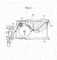
- Fig. 3 is an enlarged view illustrating a vicinity of the ink supplying section 30 shown in Fig. 1 .
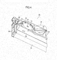
- Fig. 4 is an enlarged perspective view illustrating the vicinity of the ink supplying section 30.
- the Mobius section 27 is located immediately upstream of the ink supplying section 30 and downstream of the accommodating room 28, and causes the widthwise ends of the ink ribbon 21 to invert vertically or twist by 180° when the ink ribbon 21 is pulled in the direction of travel of the ink ribbon 21.
- a ribbon guide 34 is located between the ink roll 31 and the Mobius section 27, and guides the ink ribbon 21 in a manner , that the ink ribbon 21 does not contact the circumferential surface of the ink roll 31.
- the ink ribbon 21 is pulled out of the accommodating room 28 and is then inverted by the Mobius section 27.
- the ink ribbon 21 moves into contact with the ink transfer roller 33 to receive the ink K.
- the ink ribbon 21 then exits the casing 22 through the guide 22b and advances from the guide 22b to the guide 22a in a direction shown by arrow X ( Fig. 1 ) , passing through a gap between the print head 17 and the print paper P.
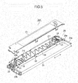
- Fig. 5 is an enlarged perspective view of an ink ribbon cartridge 20A as a comparative example.
- the ink ribbon cartridge 20A has substantially the same configuration as the ink ribbon cartridge 20 and differs only in that the ink supplying section 30 is not employed.
- Fig. 6 is a partially enlarged view of a vicinity of the Mobius section 27 shown in Fig. 5 .
- Fig. 7 is a partially enlarged view illustration a vicinity of the Mobius section.
- the ink supplying section 30 ( Fig. 4 ) is not located in the vicinity of the ribbon exit 28b of the accommodating room 28.
- the ink ribbon 21 exiting the accommodating room 28 is inverted or twisted by 180° by the Mobius section 27. Shortly after being inverted, the ink ribbon 21 exits the ink ribbon cartridge 20 through the guide 22b, and passes through a gap between the print head 17 and the print paper P.
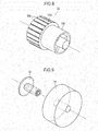
- Fig. 8 is an enlarged perspective view of the ink transfer roller 33 shown in Fig. 1 .
- the ink transfer roller 33 is a rotatable body substantially in the shape of a cylinder.
- the ink transfer roller 33 rotates in contact with the ink roller 31 so that the ink K is supplied from the ink roll 31 to the ink transfer roller 33.
- the ink transfer roller 33 has a transfer section 33a and a non-transfer section 33b.
- the transfer section 33a contacts an area (e.g., 21a) in the lower half of the width W of the ink ribbon 21 and supplies the ink K to the ink ribbon 21.
- the non-transfer section 33b has a smaller diameter than the transfer section 33a and therefore does not contact the ink ribbon 21.
- the transfer section 33a has a circumferential surface with straight groves 33c formed therein, or a knurled surface.
- the straight grooves 33c effectively holds the ink therein.
- the ink ribbon cartridge 20 is installed into the printer 10 with the ink transfer roller 33 oriented such that the transfer section 33a is at a lower position and the non-transfer section 33b is at an upper position in a gravitational direction.
- Fig. 9 is an enlarged perspective view illustrating the configuration of the ink roll 31 and ink roll wheel 32 shown in Fig. 1 .
- the ink roll 31 is formed of a cylindrical felt material which is impregnated with the ink K.
- the ink K is supplied from the circumferential surface of the ink roll 31 to the ink transfer roller 33.
- the ink wheel 32 extends through the center of the ink roll 31 and drives the ink roll 31 to rotate.
- the ink roll 31 supplies the ink K little by little to the ink transfer roller 33.
- the ink in the ink roll 31 migrates from a portion near the rotational center of the ink roll 31 to the outer circumferential surface due to centrifugal force, so that the ink K inside the ink ribbon 31 can be thoroughly used without leaving a significant portion of ink unused.
- the ink roll 31 rotates at a speed of about 0.5 rps.
- Fig. 10 is an enlarged cross-sectional view of the ink supplying section 30.
- the area in the lower half of the ink roll 31 holds the ink K therein.
- the print head 17 is configured to strike the area in the lower half of the width W of the ink ribbon to print on the print paper.
- the upper half (second area) of the ink roll 31 is not in contact with the ink transfer roller 33, and only the lower half of the ink transfer roller 33 or the transfer section 33a is in contact with the lower half of the width W of the ink ribbon 21. Since the ink ribbon 21 makes a Mobius loop, the ink K is supplied to two halves of the width W of the ink ribbon 21 alternately upper half and lower half each time the ink ribbon 21 makes a complete revolution.
- the running of the ink ribbon 21 causes the ink transfer roller 33 to rotate and the rotation of the ink transfer roller 33 causes the ink roll 31 to rotate.
- Fig. 11 illustrates the positional relation among the print head 17, ink ribbon 21, and print paper P.
- the print head 17 is carried on the carriage 11 ( Fig. 2A ) and runs across the print paper P at predetermined pitches in a direction parallel to the print paper, while the wires striking the ink ribbon 21 to print on the print paper P.
- the wires strike an inner side of a loop of the ink ribbon 21 on which the ink K is supplied by the ink transfer roller 33. In this manner, the ink K in the ink ribbon 21 is transferred onto the print paper P, minimizing the chance of the ink in the ink ribbon of contaminating the print paper P.
- Fig. 12 illustrates areas of the ink ribbon that contribute to the printing operation.
- a lower half of the width W of the ink ribbon 21 has an area (e.g., 21a) that directly faces the wires of the print head 17 during a preceding one of two consecutive revolutions of the ink ribbon 21.
- An upper half of the width W of the ink ribbon has an area (e.g., 21b) that directly faces the wires of the print head 17 during a following one of the two consecutive revolutions of the ink ribbon 21.
- Buffer areas 21c, 21d, and 21e are provided to isolate the areas 21b and 21a.
- the ink ribbon (21) is oriented such that the lower half (first area) of the ink ribbon 21 is lower than the longitudinal centerline of the ink ribbon 21 and the upper half (second area) of the ink ribbon 21 is upper than the longitudinal centerline.
- the width of the ink ribbon 21 is oriented such that the lower half of the width W and the upper half of the width W are aligned generally vertical but may not be oriented exactly in a gravitational direction.
- the ink ribbon 21 is pulled in by the pull-in mechanism 29 through the entrance 28a of the accommodating room 28, the ink ribbon 21 running in the X direction.
- the pull-in mechanism 29 and the tension spring 26 cooperate to pull the ink ribbon 21 with tension therein.
- the ink ribbon 21 is thus pulled by the pull-in mechanism 29, so that the ink ribbon 21 is inverted vertically or twisted by 180° by the Mobius loop section 27. After having passed through the Mobius loop, the ink ribbon 21 moves into contact with the ink transfer roller 33 so that the ink K is supplied to the lower half of the width W of the ink ribbon 21. The ink ribbon 21 then exits through the guide 22b and runs through the gap between the print head 17 and the print paper P.
- the lower half of the ink roll 31 holds most of the ink K therein and supplies the ink K to the ink transfer roller 33.
- the ink transfer roller 33 is in contact with the ink ribbon 21. As the ink ribbon 21 runs, the ink transfer roller 33 is driven in rotation due to the friction between the ink ribbon 21 and the ink transfer roller 33.
- the ink ribbon cartridge 20 according to the first embodiment provides the following effects.
- the printer 10 uses the ink ribbon cartridge 20. There is no need for replacing the ink ribbon cartridge 20 frequently since the ink ribbon cartridge 20 has a long life. In addition, the printer is capable of printing a vivid image since printing is performed shortly after the ink K is supplied to the ink ribbon 21.
- Fig. 13 is an enlarged perspective view of an ink ribbon cartridge 20A according to a second embodiment.
- the configuration of the ink ribbon cartridge 20A is substantially the same as that of the ink ribbon cartridge 20 of the first embodiment.
- the ink ribbon cartridge 20A differs from the ink ribbon cartridge 20 in that the ink transfer roller 33 is not used and an ink supplying section 30A is used.
- the ink ribbon cartridge 20A includes a casing 22 and a cover 23.
- the casing 22 includes an accommodating room 28 that accommodates a portion 21f of the ink ribbon 21 arranged in full fanfold fashion in such a manner that alternate loose folds or loops preferably extend substantially to the interior surface of each of the opposed inner wall of the casing 22.
- the cover 23 covers the ink ribbon 21, other mechanisms, and structures in the casing 22 to protect them from the environment.
- the casing 22 includes the accommodating room 28, guides 22a and 22b, a drive gear 24, an idle gear 25, a tension spring 26, a Mobius section 27, and the ink supplying section 30A.
- Fig. 14 is an enlarged top view of a vicinity of the ink supplying section 30A shown in Fig. 13 .
- Fig. 15 is an enlarged perspective view of a vicinity of the ink supplying section 30A.
- the ink supplying section 30A includes an ink roll wheel 32, an ink roll 31A, and an ink roll stopper 35.
- the ink roll wheel 32 and ink roll stopper 35 cooperate to hold the ink roll 31A in position.
- Fig. 16 is a perspective view of the ink roll 31A, ink roll wheel 32, and ink roll stopper 35 shown in Fig. 13 .
- the ink roll wheel 32 extends through the ink roll 31A and ink roll stopper 35 so that ink roll 31A, ink roll wheel 32, and ink roll stopper 35 are concentric.
- the ink roll 31A has an axial length approximately half of that of the ink roll 31 of the first embodiment.
- the ink roll 31A is driven in rotation by the ink ribbon 21 that advances in contact with the ink roll 31A. As the ink ribbon 21 advances, the ink roll 31A supplies ink K to the ink ribbon 21.
- the ink roll stopper 35 has a diameter D2 which is smaller than that D1 of the ink roll 31A.
- the ink cartridge 20A is installed into a printer 10 ( Fig. 2A ) with the ink roll 31A positioned below the ink roll stopper 35, the ink roll 31A and the ink roll stopper 35 being aligned in a gravitational direction.
- Fig. 17 is an enlarged cross-sectional view of the ink supplying section 30A.
- the ink roll 31 holds the ink K therein.
- the print head 17 is configured to strike the lower half of the width W of the ink ribbon 21 to print on the print paper P.
- the ink roll 31A is in contact with the lower half of the width W of the ink ribbon 21.
- Fig. 13 illustrates the ink supplying section 30 located in the vicinity of an exit 28b.
- the ink roll 31A is journaled on the ink roll wheel 32 and is freely rotatable.
- the ink roll stopper 35 is over the ink roll 31A, and prevents the ink roll 31A from being pulled off the ink roll wheel 32.
- the ink roll 31A is impregnated with the ink K, and is in contact with the lower half of the width W of the ink ribbon 21. There is a small gap between the upper half of the width W of the ink ribbon 21 and the circumferential surface of the ink roll stopper 35.
- the ink roll 31A is driven in rotation by means of friction between the lower half of the width W of the ink ribbon 21 and the ink roll 31A.
- the ink ribbon 21 is pulled in by the pull-in mechanism 29 through the entrance 28a of the accommodating room 28, the ink ribbon 21 running in the X direction.
- the pull-in mechanism 29 and the tension spring 26 cooperate to pull the ink ribbon 21 with tension therein.
- the ink ribbon 21 is thus pulled in by the pull-in mechanism 29, so that the ink ribbon 21 is inverted vertically or twisted by 180° by the Mobius loop section 27.
- the lower half of the width W of the ink ribbon 21 moves into contact with the ink roll 31A so that the ink K is supplied to the lower half of the width W of the ink ribbon 21.
- the ink ribbon 21 then exits the casing 22 through the guide 22b, and runs through the gap between the print head 17 and the print paper P.
- the lower half of the ink roll 31A holds most of the ink K therein and supplies the ink K to the ink ribbon 21.
- the ink roll 31 is in contact with the ink ribbon 21 and is driven in rotation as the ink ribbon 21 runs.
- the ink roll 31A supplies the ink K to an area of the ink ribbon 21 in contact with the ink roll 31A.
- the ink ribbon cartridge 20A according to the second embodiment provides the following effects in addition to those of the first embodiment.
- the second embodiment does not use the ink transfer roller 33.
- the second embodiment can be free from poor transfer of the ink K which would otherwise be caused by wear and/or improper rotation of the ink transfer roller 33.
- the printer 10 uses the ink ribbon cartridge 20A.
- the printer 10 is capable of printing with good, reliable print results since the ink ribbon cartridge 20A is free from improper ink transfer operation.
- Modifications may include the following.
Landscapes
- Impression-Transfer Materials And Handling Thereof (AREA)
Abstract
Description
- The present invention relates to an ink ribbon cartridge and a printer incorporating the ink ribbon cartridge.
- A conventional built-in ink ribbon cartridge for use in a printer includes a casing that accommodates an endless ink ribbon that forms a Mobius loop, and a cover that closes the casing to protect the ink ribbon from the environment.
- The casing includes two projections such that the ink ribbon outside the casing is held taut between the two projects.
- The casing accommodates a pull-in mechanism, an urging member, and a Mobius section. The pulling mechanism is disposed near a ribbon entrance, and pulls in the ink ribbon into the casing. The urging member applies a tension force to the ink ribbon when the ink ribbon is pulled out of a ribbon exit. The Mobius section provides in the ribbon an inversion or twist of 180° in a manner to form a Mobius loop.
- Conventional built-in ink cartridges suffer from a problem in that if an ink supplying mechanism is built in, the ink is not used efficiently.
- An object of the invention is to provide an ink ribbon cartridge in which ink is supplied only to a half of the width of the ink ribbon.
- Another object of the invention is to provide an ink ribbon cartridge in which the ink is consumed efficiently without leaving some portion of ink unused.
- Still another object of the invention is to provide a printer that operates at low running cost.
- Yet another object of the invention is to provide a printer that incorporates the ink ribbon cartridge.
- An ink ribbon cartridge holds an ink ribbon impregnated with ink. A casing (22) includes two guide portions projecting from the casing. An ink ribbon (21) is formed in a Mobius loop. The ink ribbon includes a width (W) . The ink ribbon includes a first area (21a+21e or 21b+21c) of the width and a second area (21b+21c or 21a+21e) of the width (W), and is housed in the casing (22). The ink ribbon exits the casing from a free end of one of the two guide portions (22a, 22b) and enters the casing from a free end of the other of the two guide portions. An ink supplying section supplies ink to the ink ribbon (21) at an area (21a) in the first area of the width.
- Further scope of applicability of the present invention will become apparent from the detailed description given hereinafter. However, it should be understood that the detailed description and specific examples, while indicating preferred embodiments of the invention, are given by way of illustration only, since various changes and modifications within the spirit and scope of the invention will become apparent to those skilled in the art from this detailed description.
- The present invention will become more fully understood from the detailed description given hereinbelow and the accompanying drawings which are given by way of illustration only, and thus are not limiting the present invention, and wherein:
-
Fig. 1 is a perspective view illustrating a printer according to a first embodiment; -
Fig. 2A is an exploded perspective view illustrating an ink ribbon cartridge shown inFig. 1 ; -
Fig. 2B is an enlarged view of a pull-in mechanism; -
Fig. 3 is an enlarged view illustrating a vicinity of an ink supplying section shown inFig. 2A ; -
Fig. 4 is an enlarged perspective view illustrating a vicinity of the ink supplying section; -
Fig. 5 is an enlarged perspective view of an ink ribbon cartridge as a comparative example; -
Fig. 6 is a partially enlarged view of a vicinity of the Mobius section shown inFig. 5 ; -
Fig. 7 is a partially enlarged view illustration a vicinity of the Mobius section; -
Fig. 8 is an enlarged perspective view of the ink transfer roller shown inFig. 2 ; -
Fig. 9 is an enlarged perspective view illustrating the configuration of the ink roll and ink roll wheel shown inFig. 2A ; -
Fig. 10 is an enlarged cross-sectional view of the ink supplying section; -
Fig. 11 illustrates the positional relation among the print head, ink ribbon, and print paper; -
Fig. 12 illustrates areas of the ink ribbon that contribute to a printing operation; -
Fig. 13 is an enlarged perspective view of an ink ribbon cartridge according to a second embodiment; -
Fig. 14 is an enlarged top view of a vicinity of an ink supplying section shown inFig. 13 ; -
Fig. 15 is an enlarged perspective view of a vicinity of the ink supplying section; -
Fig. 16 is an exploded perspective view of the ink roll, ink roll wheel, and ink roll stopper shown inFig. 13 ; and -
Fig. 17 is an enlarged cross-sectional view of the ink supplying section. -
Fig. 1 is a perspective view illustrating aprinter 10 according to a first embodiment. - The
printer 10 takes the form of, for example, an impact dot printer, and receives print data from, for example, a host apparatus. Theprinter 10 prints the print data on a print medium (e.g., print paper) P by causing printing wires to strike an ink ribbon against a print medium P. - A
carriage 11 is located to face aplaten 12 and carries aprint head 17 thereon. The print head 17 (not shown) includes a plurality of wires to strike the ink ribbon against the paper P to print characters, symbols, and graphics. Theplaten 12 rotates by a certain angle to advance the print paper P by a predetermined distance, every time the carriage completes a scanning cycle across the print paper P. The print paper P passes through the gap defined between theprint head 17 and theplaten 12, advancing in a direction substantially perpendicular to a direction in which thecarriage 11 moves. A pull-upguide 13 serves to minimize page-to-page shift of the print paper if the print paper P is continuous copy paper. - The
carriage 11 moves at predetermined pitches across the paper P in a direction in which theplaten 12 extends longitudinally, as theprint head 17 prints on the paper P. Theink ribbon cartridge 20 is installed into the printer from above. - Covers 14 (only one of which is shown) close side portions of the
printer 10 to protect a variety of mechanisms (not shown) in theprinter 10 from the environment. Anaccess cover 15 protects the user from inadvertently touching thecarriage 11 during printing. Arear sheet guide 16 feeds single sheets during printing in a manual feed mode. -
Fig. 2A is an exploded perspective view illustrating anink ribbon cartridge 20 shown inFig. 1 .Fig. 2B is an enlarged view of a pull-inmechanism 29. - The
ink ribbon cartridge 20 includes acasing 22 and acover 23. Thecasing 22 includes anaccommodating room 28 that accommodates a fan-foldedportion 21f of theink ribbon 21. Theportion 21f is arranged in full fanfold fashion in such a manner that alternate loose folds or loops preferably extend substantially to the interior surface of each of the opposed inner wall of thecasing 22. Thecover 23 covers theink ribbon 21, other mechanisms, and structures in thecasing 22 to protect from the environment. -
Guides casing 22 extends longitudinally. Theink ribbon 21 runs from the free end of theguide 22b to the free end of theguide 22a. Carrying theprint head 17 thereon, thecarriage 11 moves back and forth along theplaten 12 during printing in an area defined by thecasing 22, guides 22a and 22b, and theink ribbon 21 running outside of thecasing 22, - The pull-in
mechanism 29 for pulling in theink ribbon 21 is located in the vicinity of aribbon entrance 28a of theink ribbon cartridge 20. The pull-inmechanism 29 includes adrive gear 24 and a drivengear 25. As shown inFig. 2B , thedrive gear 24 and drivengear 25 are in meshing engagement with each other with theink ribbon 21 therebetween. When thedrive gear 24 rotates, thedrive gear 24 and drivengear 25 cooperate with each other to pull in theink ribbon 21 through theribbon entrance 28a. - An urging member 26 (e.g., tension spring) is located inside the
casing 22 in the vicinity of theguide 22b, and urges theink ribbon 21 against thecasing 22, thereby applying some drag on the ink ribbon so that theink ribbon 21 outside thecasing 22 is in tension when theink ribbon 21 is drawn out of thecasing 22. Anink supplying section 30 is disposed immediately upstream of the urgingmember 26 with respect to the path in which theink ribbon 21 advances. TheMobius section 27 is located immediately upstream of theink supplying section 30, and causes the widthwise ends of the ink ribbon to invert vertically or twist by 180°. - The
ink supplying section 30 includes an ink-impregnated body orink roll 31, andink roll wheel 32, and anink transfer roller 33. Theink roll 31 is formed of felt material which is impregnated with the ink K, and freely rotates about theink roll wheel 32 which is also freely rotatable. Theink roll 31 is in resilient contact with theink transfer roller 33, so that the ink K is transferred from theink transfer roller 33 onto anarea 21a in the lower half (first area) of the width W of theink ribbon 21 as theink ribbon 21 advances in contact with theink transfer roller 33. -
Fig. 3 is an enlarged view illustrating a vicinity of theink supplying section 30 shown inFig. 1 . -
Fig. 4 is an enlarged perspective view illustrating the vicinity of theink supplying section 30. - The
Mobius section 27 is located immediately upstream of theink supplying section 30 and downstream of theaccommodating room 28, and causes the widthwise ends of theink ribbon 21 to invert vertically or twist by 180° when theink ribbon 21 is pulled in the direction of travel of theink ribbon 21. - A
ribbon guide 34 is located between theink roll 31 and theMobius section 27, and guides theink ribbon 21 in a manner , that theink ribbon 21 does not contact the circumferential surface of theink roll 31. - The
ink ribbon 21 is pulled out of theaccommodating room 28 and is then inverted by theMobius section 27. Theink ribbon 21 moves into contact with theink transfer roller 33 to receive the ink K. Theink ribbon 21 then exits thecasing 22 through theguide 22b and advances from theguide 22b to theguide 22a in a direction shown by arrow X (Fig. 1 ) , passing through a gap between theprint head 17 and the print paper P. -
Fig. 5 is an enlarged perspective view of anink ribbon cartridge 20A as a comparative example. - The
ink ribbon cartridge 20A has substantially the same configuration as theink ribbon cartridge 20 and differs only in that theink supplying section 30 is not employed. -
Fig. 6 is a partially enlarged view of a vicinity of theMobius section 27 shown inFig. 5 .Fig. 7 is a partially enlarged view illustration a vicinity of the Mobius section. - It is to be noted that the ink supplying section 30 (
Fig. 4 ) is not located in the vicinity of theribbon exit 28b of theaccommodating room 28. Theink ribbon 21 exiting theaccommodating room 28 is inverted or twisted by 180° by theMobius section 27. Shortly after being inverted, theink ribbon 21 exits theink ribbon cartridge 20 through theguide 22b, and passes through a gap between theprint head 17 and the print paper P. -
Fig. 8 is an enlarged perspective view of theink transfer roller 33 shown inFig. 1 . Theink transfer roller 33 is a rotatable body substantially in the shape of a cylinder. Theink transfer roller 33 rotates in contact with theink roller 31 so that the ink K is supplied from theink roll 31 to theink transfer roller 33. Theink transfer roller 33 has atransfer section 33a and anon-transfer section 33b. Thetransfer section 33a contacts an area (e.g., 21a) in the lower half of the width W of theink ribbon 21 and supplies the ink K to theink ribbon 21. Thenon-transfer section 33b has a smaller diameter than thetransfer section 33a and therefore does not contact theink ribbon 21. Thetransfer section 33a has a circumferential surface withstraight groves 33c formed therein, or a knurled surface. Thestraight grooves 33c effectively holds the ink therein. Theink ribbon cartridge 20 is installed into theprinter 10 with theink transfer roller 33 oriented such that thetransfer section 33a is at a lower position and thenon-transfer section 33b is at an upper position in a gravitational direction. -
Fig. 9 is an enlarged perspective view illustrating the configuration of theink roll 31 andink roll wheel 32 shown inFig. 1 . - The
ink roll 31 is formed of a cylindrical felt material which is impregnated with the ink K. The ink K is supplied from the circumferential surface of theink roll 31 to theink transfer roller 33. Theink wheel 32 extends through the center of theink roll 31 and drives theink roll 31 to rotate. Theink roll 31 supplies the ink K little by little to theink transfer roller 33. The ink in theink roll 31 migrates from a portion near the rotational center of theink roll 31 to the outer circumferential surface due to centrifugal force, so that the ink K inside theink ribbon 31 can be thoroughly used without leaving a significant portion of ink unused. Theink roll 31 rotates at a speed of about 0.5 rps. -
Fig. 10 is an enlarged cross-sectional view of theink supplying section 30. The area in the lower half of theink roll 31 holds the ink K therein. Theprint head 17 is configured to strike the area in the lower half of the width W of the ink ribbon to print on the print paper. For this reason, the upper half (second area) of theink roll 31 is not in contact with theink transfer roller 33, and only the lower half of theink transfer roller 33 or thetransfer section 33a is in contact with the lower half of the width W of theink ribbon 21. Since theink ribbon 21 makes a Mobius loop, the ink K is supplied to two halves of the width W of theink ribbon 21 alternately upper half and lower half each time theink ribbon 21 makes a complete revolution. - The running of the
ink ribbon 21 causes theink transfer roller 33 to rotate and the rotation of theink transfer roller 33 causes theink roll 31 to rotate. -
Fig. 11 illustrates the positional relation among theprint head 17,ink ribbon 21, and print paper P. Theprint head 17 is carried on the carriage 11 (Fig. 2A ) and runs across the print paper P at predetermined pitches in a direction parallel to the print paper, while the wires striking theink ribbon 21 to print on the print paper P. It is to be noted that the wires strike an inner side of a loop of theink ribbon 21 on which the ink K is supplied by theink transfer roller 33. In this manner, the ink K in theink ribbon 21 is transferred onto the print paper P, minimizing the chance of the ink in the ink ribbon of contaminating the print paper P. -
Fig. 12 illustrates areas of the ink ribbon that contribute to the printing operation. A lower half of the width W of theink ribbon 21 has an area (e.g., 21a) that directly faces the wires of theprint head 17 during a preceding one of two consecutive revolutions of theink ribbon 21. An upper half of the width W of the ink ribbon has an area (e.g., 21b) that directly faces the wires of theprint head 17 during a following one of the two consecutive revolutions of theink ribbon 21.Buffer areas areas ink ribbon 21 is lower than the longitudinal centerline of theink ribbon 21 and the upper half (second area) of theink ribbon 21 is upper than the longitudinal centerline. Thus, once the ink ribbon cartridge has been attached to the printer, the width of theink ribbon 21 is oriented such that the lower half of the width W and the upper half of the width W are aligned generally vertical but may not be oriented exactly in a gravitational direction. - Referring to
Fig. 2A , theink ribbon 21 is pulled in by the pull-inmechanism 29 through theentrance 28a of theaccommodating room 28, theink ribbon 21 running in the X direction. The pull-inmechanism 29 and thetension spring 26 cooperate to pull theink ribbon 21 with tension therein. - Referring to
Figs. 3 and12 , theink ribbon 21 is thus pulled by the pull-inmechanism 29, so that theink ribbon 21 is inverted vertically or twisted by 180° by theMobius loop section 27. After having passed through the Mobius loop, theink ribbon 21 moves into contact with theink transfer roller 33 so that the ink K is supplied to the lower half of the width W of theink ribbon 21. Theink ribbon 21 then exits through theguide 22b and runs through the gap between theprint head 17 and the print paper P. - Referring to
Fig. 10 , the lower half of theink roll 31 holds most of the ink K therein and supplies the ink K to theink transfer roller 33. - The
ink transfer roller 33 is in contact with theink ribbon 21. As theink ribbon 21 runs, theink transfer roller 33 is driven in rotation due to the friction between theink ribbon 21 and theink transfer roller 33. - The
ink ribbon cartridge 20 according to the first embodiment provides the following effects. - (1) The
ink supplying section 30 supplies the ink K to theink ribbon 21, thereby ensuring a prolonged printing operation of theink ribbon cartridge 20 as opposed to an ink ribbon cartridge without theink supplying section 30. - (2) The
ink supplying section 30 is disposed as close a location to theribbon exit 28b as possible, so that the fresh ink supplied to theink ribbon 21 is promptly consumed in printing. This configuration provides vivid print results. - (3) The impregnated ink K tends to gather at a lower portion of the
ink roll 31. Taking this tendency into account, thetransfer section 33a is formed at the lower half of theink transfer roller 33. Thus, the ink K may be used efficiently. - (4) The
ink supplying section 30 is located downstream of theMobius section 27 with respect to the direction of travel of the ink ribbon and upstream of theprint head 17. This implies that the ink K is always supplied to the inside of the loop of theink ribbon 21 between theMobius section 27 and theprint head 17. This configuration minimizes the chance of theink ribbon 21 of contaminating the print paper P. - The
printer 10 according to the present invention uses theink ribbon cartridge 20. There is no need for replacing theink ribbon cartridge 20 frequently since theink ribbon cartridge 20 has a long life. In addition, the printer is capable of printing a vivid image since printing is performed shortly after the ink K is supplied to theink ribbon 21. -
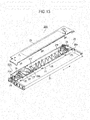
Fig. 13 is an enlarged perspective view of anink ribbon cartridge 20A according to a second embodiment. - The configuration of the
ink ribbon cartridge 20A is substantially the same as that of theink ribbon cartridge 20 of the first embodiment. Theink ribbon cartridge 20A differs from theink ribbon cartridge 20 in that theink transfer roller 33 is not used and anink supplying section 30A is used. Theink ribbon cartridge 20A includes acasing 22 and acover 23. Thecasing 22 includes anaccommodating room 28 that accommodates aportion 21f of theink ribbon 21 arranged in full fanfold fashion in such a manner that alternate loose folds or loops preferably extend substantially to the interior surface of each of the opposed inner wall of thecasing 22. Thecover 23 covers theink ribbon 21, other mechanisms, and structures in thecasing 22 to protect them from the environment. Thecasing 22 includes theaccommodating room 28, guides 22a and 22b, adrive gear 24, anidle gear 25, atension spring 26, aMobius section 27, and theink supplying section 30A. -
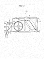
Fig. 14 is an enlarged top view of a vicinity of theink supplying section 30A shown inFig. 13 .Fig. 15 is an enlarged perspective view of a vicinity of theink supplying section 30A. - The
ink supplying section 30A includes anink roll wheel 32, anink roll 31A, and anink roll stopper 35. Theink roll wheel 32 andink roll stopper 35 cooperate to hold theink roll 31A in position. -
Fig. 16 is a perspective view of theink roll 31A,ink roll wheel 32, andink roll stopper 35 shown inFig. 13 . - The
ink roll wheel 32 extends through theink roll 31A andink roll stopper 35 so thatink roll 31A,ink roll wheel 32, andink roll stopper 35 are concentric. Theink roll 31A has an axial length approximately half of that of theink roll 31 of the first embodiment. Theink roll 31A is driven in rotation by theink ribbon 21 that advances in contact with theink roll 31A. As theink ribbon 21 advances, theink roll 31A supplies ink K to theink ribbon 21. - The
ink roll stopper 35 has a diameter D2 which is smaller than that D1 of theink roll 31A. Theink cartridge 20A is installed into a printer 10 (Fig. 2A ) with theink roll 31A positioned below theink roll stopper 35, theink roll 31A and theink roll stopper 35 being aligned in a gravitational direction. -
Fig. 17 is an enlarged cross-sectional view of theink supplying section 30A. Theink roll 31 holds the ink K therein. Theprint head 17 is configured to strike the lower half of the width W of theink ribbon 21 to print on the print paper P. Theink roll 31A is in contact with the lower half of the width W of theink ribbon 21. -
Fig. 13 illustrates theink supplying section 30 located in the vicinity of anexit 28b. Theink roll 31A is journaled on theink roll wheel 32 and is freely rotatable. Theink roll stopper 35 is over theink roll 31A, and prevents theink roll 31A from being pulled off theink roll wheel 32. Theink roll 31A is impregnated with the ink K, and is in contact with the lower half of the width W of theink ribbon 21. There is a small gap between the upper half of the width W of theink ribbon 21 and the circumferential surface of theink roll stopper 35. - As the
ink ribbon 21 runs in contact with theink roll 31A, theink roll 31A is driven in rotation by means of friction between the lower half of the width W of theink ribbon 21 and theink roll 31A. - Referring to
Fig. 13 , theink ribbon 21 is pulled in by the pull-inmechanism 29 through theentrance 28a of theaccommodating room 28, theink ribbon 21 running in the X direction. The pull-inmechanism 29 and thetension spring 26 cooperate to pull theink ribbon 21 with tension therein. - Referring to
Figs. 13 and14 , theink ribbon 21 is thus pulled in by the pull-inmechanism 29, so that theink ribbon 21 is inverted vertically or twisted by 180° by theMobius loop section 27. After having passed through the Mobius loop, the lower half of the width W of theink ribbon 21 moves into contact with theink roll 31A so that the ink K is supplied to the lower half of the width W of theink ribbon 21. Theink ribbon 21 then exits thecasing 22 through theguide 22b, and runs through the gap between theprint head 17 and the print paper P. - Referring to
Fig. 15 , the lower half of theink roll 31A holds most of the ink K therein and supplies the ink K to theink ribbon 21. Theink roll 31 is in contact with theink ribbon 21 and is driven in rotation as theink ribbon 21 runs. Theink roll 31A supplies the ink K to an area of theink ribbon 21 in contact with theink roll 31A. - The
ink ribbon cartridge 20A according to the second embodiment provides the following effects in addition to those of the first embodiment. - The second embodiment does not use the
ink transfer roller 33. Thus, the second embodiment can be free from poor transfer of the ink K which would otherwise be caused by wear and/or improper rotation of theink transfer roller 33. - The
printer 10 according to the present invention uses theink ribbon cartridge 20A. Theprinter 10 is capable of printing with good, reliable print results since theink ribbon cartridge 20A is free from improper ink transfer operation. - A variety of modifications may be made to the first and second embodiments. Modifications may include the following.
- (1) The first and second embodiments have been described in terms of a wire
dot impact printer 10 which is an output apparatus for a computer. Theprinter 10 may be an automatic apparatus including an automatic teller machine (ATM) or a printer that is incorporated in a cash register and prints receipts. - (2) The
printer 10 is not limited to the wire dot impact printer but may be type printers in which a print head has characters. - (3) The first and second embodiments may be modified in order to implement an ink ribbon cartridge that can be converted into an ink ribbon cartridge with an ink supplying section or an ink ribbon cartridge without an ink supplying section.
- (4) The first and second embodiments may be modified to implement an ink ribbon cartridge in which a Mobius section is located in the vicinity of an entrance of a casing into which the ink ribbon enters.
- The invention being thus described, it will be obvious that the same may be varied in many ways. Such variations are not to be regarded as a departure from the spirit and scope of the invention, and all such modifications as would be obvious to one skilled in the art intended to be included within the scope of the following claims.
Claims (13)
- An ink ribbon cartridge, CHARACTERIZED by:a casing (22) including two guide portions (22a, 22b) projecting from the casing;an ink ribbon (21) formed in a Mobius loop, the ink ribbon including a first area and a second area, the ink ribbon (21) being housed in the casing (22) and exiting the casing (22) from a free end of one of the two guide portions and entering the casing (22) from a free end of the other of the two guide portions; andan ink supplying section (30, 30A) that supplies ink (K) to the ink ribbon (21) at an area (21a, 21b) in the first area.
- The ink ribbon cartridge according to claim 1, wherein the ink ribbon (21) has a portion (21f) arranged in a fanfold fashion and housed in the casing (22);
wherein the ink ribbon cartridge further includes a Mobius section (27) that causes widthwise ends of the ink ribbon to twist by 180°, the Mobius section (27) being disposed immediately upstream of the ink supplying section (30, 30A) with respect to travel of the ink ribbon (21). - The ink ribbon cartridge according to claim 1 or claim 2, wherein the ink supplying section (30) includes:an ink holding member (31) impregnated with the ink therein;
andan ink transfer roller (33) including a surface area (33a) in contact with a cylindrical surface of the ink holding member (31), the surface area also being in contact with the ink ribbon (21), wherein the ink transfer roller (33) rotates while receiving the ink (K) from the ink holding member (31) and supplying the received ink (K) to the ink ribbon (21). - The ink ribbon cartridge according to claim 3, wherein the ink ribbon (21) is oriented such that the first area of the ink ribbon is lower than a longitudinal centerline of the ink ribbon and the second area of the ink ribbon is upper than the longitudinal centerline, wherein ink holding member (31) rotates in contact with the ink transfer roller (33) and the surface area contacts the area in the first area of the ink ribbon so that the ink is supplied to the area (21a) in the first area of the ink ribbon (21).
- The ink ribbon cartridge according to claim 1 or claim 2, wherein the ink ribbon (21) is oriented such that the first area of the ink ribbon is lower than a longitudinal centerline of the ink ribbon and the second area of the ink ribbon is upper than the longitudinal centerline;
wherein the ink supplying section (30A) includes an ink holding member (31A) impregnated with the ink therein, the ink holding member being in contact with the area in the first area of the ink ribbon (21) to supply the ink (K) to the area (21a) in the first area of the ink ribbon (21). - The ink ribbon cartridge according to claim 3 or claim 4, wherein the ink holding member (31) is a cylinder of felt material; and
wherein the ink supplying section (30) includes a supporting member (32) by which the ink holding member is rotatably supported. - The ink ribbon cartridge according to claim 1, wherein the first area is a first half of the width of the ink ribbon and the second area is a second half of the width of the ink ribbon.
- The ink ribbon cartridge according to claim 1, wherein the ink supplying section (30) includes:a transfer section (33a) that faces the first area of the ink ribbon and supplies the ink to the first area; anda non-transfer section (33b) that faces the second area of the ink ribbon and does not supply the ink to the second area.
- The ink ribbon cartridge according to claim 8, wherein the ink supplying section (30) includes a cylindrical body including the transfer section and the non-transfer section;
wherein the non-transfer section has a smaller diameter than the transfer section. - The ink ribbon cartridge according to claim 8 further comprising:a Mobius section (27) that causes widthwise ends of the ink ribbon to twist by 180° ;a ribbon guide (34) located upstream of the ink supplying section and downstream of the Mobius section;wherein the ink supplying section (30) includes an ink holding member (31), and the ribbon guide guides the ink ribbon such that the ink ribbon is away from the ink holding member.
- A printer incorporating the ink ribbon cartridge according to any one of claims 1-5, 6, 7, and 8-10, and further comprising:a printing mechanism (17) including striking members that strike the ink ribbon to transfer the ink in the ink ribbon onto the print medium.
- The printer according to claim 11, wherein the striking members faces the area in the first area when the ink ribbon cartridge has been attached to the printer.
- The printer according to claim 12, wherein the striking members are wires that strike the first area during a printing operation.
Applications Claiming Priority (1)
| Application Number | Priority Date | Filing Date | Title |
|---|---|---|---|
| JP2010259102A JP5345602B2 (en) | 2010-11-19 | 2010-11-19 | Ink ribbon cartridge and printing apparatus |
Publications (3)
| Publication Number | Publication Date |
|---|---|
| EP2455226A2 true EP2455226A2 (en) | 2012-05-23 |
| EP2455226A3 EP2455226A3 (en) | 2013-01-23 |
| EP2455226B1 EP2455226B1 (en) | 2018-10-31 |
Family
ID=45217233
Family Applications (1)
| Application Number | Title | Priority Date | Filing Date |
|---|---|---|---|
| EP11189658.5A Active EP2455226B1 (en) | 2010-11-19 | 2011-11-18 | Ink ribbon cartridge and printer |
Country Status (4)
| Country | Link |
|---|---|
| US (1) | US9056513B2 (en) |
| EP (1) | EP2455226B1 (en) |
| JP (1) | JP5345602B2 (en) |
| CN (1) | CN102529461B (en) |
Families Citing this family (2)
| Publication number | Priority date | Publication date | Assignee | Title |
|---|---|---|---|---|
| JP6331774B2 (en) * | 2014-06-30 | 2018-05-30 | ブラザー工業株式会社 | Self-laminating tape cassette, tape printer, and tape printer |
| CN112793296A (en) * | 2020-12-30 | 2021-05-14 | 海南金橡晨星塑料有限公司 | Plastic product surface pattern printing machine |
Family Cites Families (24)
| Publication number | Priority date | Publication date | Assignee | Title |
|---|---|---|---|---|
| US3977512A (en) * | 1975-06-30 | 1976-08-31 | The Singer Company | Ribbon cassette and ribbon advance |
| DE2717076C3 (en) | 1977-04-18 | 1981-11-12 | Nixdorf Computer Ag, 4790 Paderborn | Ribbon device for printing units |
| IT1115517B (en) * | 1977-04-21 | 1986-02-03 | Honeywell Inf Systems | ENDLESS INKED BELT CARTRIDGE |
| JPS54122911U (en) * | 1978-02-16 | 1979-08-28 | ||
| US4213013A (en) | 1978-02-17 | 1980-07-15 | Bunker Ramo Corporation | Telephone network/subscriber interface device |
| US4279522A (en) * | 1978-12-07 | 1981-07-21 | Data Packaging Corporation | High speed printer cartridge |
| US4247209A (en) * | 1979-04-19 | 1981-01-27 | Teletype Corporation | Printer ribbon cartridge having lap spliced ribbon and reinking means |
| JPS59102363A (en) | 1982-12-01 | 1984-06-13 | Toyo Suisan Kk | Preparation of noodle |
| JPS59102363U (en) * | 1982-12-27 | 1984-07-10 | 富士通株式会社 | ribbon cassette |
| JPH0222858A (en) | 1988-07-11 | 1990-01-25 | Nec Corp | Semiconductor device |
| JPH0222858U (en) * | 1988-07-27 | 1990-02-15 | ||
| DE4025758A1 (en) * | 1990-08-14 | 1992-02-20 | Buettner Ag Franz | RIBBON AND METHOD FOR THE PRODUCTION THEREOF |
| JPH04107068U (en) * | 1991-02-26 | 1992-09-16 | 日本電気株式会社 | ink ribbon cassette |
| JPH0516505A (en) * | 1991-07-09 | 1993-01-26 | Tokyo Electric Co Ltd | Ink ribbon device |
| US5230575A (en) * | 1992-05-20 | 1993-07-27 | Mannesmann Tally Corporation | Segmented ink reservoir |
| JPH0723557U (en) * | 1993-10-12 | 1995-05-02 | 三菱鉛筆株式会社 | Ink ribbon sub cartridge |
| JPH07132668A (en) * | 1993-11-10 | 1995-05-23 | Oki Electric Ind Co Ltd | Ink ribbon cassette |
| US5511888A (en) * | 1994-09-20 | 1996-04-30 | Mannesmann Tally Corporation | Apparatus for re-inking the ribbon of a printer ribbon cartridge |
| JPH08156377A (en) * | 1994-12-05 | 1996-06-18 | General Kk | Ink ribbon cartridge |
| US5746522A (en) * | 1996-12-11 | 1998-05-05 | Ncr Corporation | Liquid tank re-inker using ball transfer mechanism |
| US5902057A (en) * | 1997-09-09 | 1999-05-11 | Genicom Corporation | Print ribbon cartridge with re-inker assembly |
| US6017158A (en) * | 1998-09-08 | 2000-01-25 | Tally Printer Corporation | Apparatus for reinking the ribbon of a printer ribbon cartridge |
| JP4491573B2 (en) * | 2000-07-19 | 2010-06-30 | フジコピアン株式会社 | Ink ribbon cassette |
| US20020064409A1 (en) * | 2000-10-17 | 2002-05-30 | Gtech Rhode Island Corporation | Printer ribbon cartridge with reinking roller |
-
2010
- 2010-11-19 JP JP2010259102A patent/JP5345602B2/en active Active
-
2011
- 2011-11-18 CN CN201110367807.5A patent/CN102529461B/en active Active
- 2011-11-18 US US13/300,400 patent/US9056513B2/en active Active
- 2011-11-18 EP EP11189658.5A patent/EP2455226B1/en active Active
Non-Patent Citations (1)
| Title |
|---|
| None |
Also Published As
| Publication number | Publication date |
|---|---|
| JP2012111041A (en) | 2012-06-14 |
| EP2455226B1 (en) | 2018-10-31 |
| JP5345602B2 (en) | 2013-11-20 |
| CN102529461A (en) | 2012-07-04 |
| US9056513B2 (en) | 2015-06-16 |
| EP2455226A3 (en) | 2013-01-23 |
| CN102529461B (en) | 2016-10-05 |
| US20120128398A1 (en) | 2012-05-24 |
Similar Documents
| Publication | Publication Date | Title |
|---|---|---|
| US4397574A (en) | Reloadable ribbon cassette | |
| EP2079592B1 (en) | Cartridge and printer | |
| KR101206442B1 (en) | Discharging unit and image forming apparatus having the same | |
| JPS5917955B2 (en) | Printer ribbon/cartridge | |
| CA1191384A (en) | Ribbon cartridge comprising a stuffer box intermediate a supply reel and take-up reel | |
| US4720202A (en) | Print ribbon replaceable cassette | |
| JPH08132718A (en) | Heat transfer printer | |
| EP2455226B1 (en) | Ink ribbon cartridge and printer | |
| EP0854049B1 (en) | Image recording apparatus | |
| JP7067988B2 (en) | Printer | |
| JPS6359877B2 (en) | ||
| JPS6320717B2 (en) | ||
| EP0338970B1 (en) | High-symbol density printer cartridge | |
| CN111918830B (en) | Winding device and printing device | |
| TWI692411B (en) | Winding device and printing device | |
| US5511888A (en) | Apparatus for re-inking the ribbon of a printer ribbon cartridge | |
| US6290408B1 (en) | Ribbon cassette with friction mechanism | |
| KR900007505B1 (en) | Ribbon Drive Method and Ribbon Device Enable Bidirectional Printing of Thermal Transfer Printer | |
| JPH0325970Y2 (en) | ||
| JPH0648004A (en) | Ribbon cassette | |
| EP0927642B1 (en) | Ink ribbon cartridge | |
| JP2001301293A (en) | Method for rewinding ink ribbon | |
| CA1181632A (en) | Pen type printing apparatus | |
| CA1155077A (en) | Printer with movable print point and stationary marking ribbon storage | |
| JPH05185704A (en) | Heat transfer printer and ink ribbon running method thereof |
Legal Events
| Date | Code | Title | Description |
|---|---|---|---|
| PUAI | Public reference made under article 153(3) epc to a published international application that has entered the european phase |
Free format text: ORIGINAL CODE: 0009012 |
|
| AK | Designated contracting states |
Kind code of ref document: A2 Designated state(s): AL AT BE BG CH CY CZ DE DK EE ES FI FR GB GR HR HU IE IS IT LI LT LU LV MC MK MT NL NO PL PT RO RS SE SI SK SM TR |
|
| AX | Request for extension of the european patent |
Extension state: BA ME |
|
| PUAL | Search report despatched |
Free format text: ORIGINAL CODE: 0009013 |
|
| AK | Designated contracting states |
Kind code of ref document: A3 Designated state(s): AL AT BE BG CH CY CZ DE DK EE ES FI FR GB GR HR HU IE IS IT LI LT LU LV MC MK MT NL NO PL PT RO RS SE SI SK SM TR |
|
| AX | Request for extension of the european patent |
Extension state: BA ME |
|
| RIC1 | Information provided on ipc code assigned before grant |
Ipc: B41J 32/02 20060101ALI20121220BHEP Ipc: B41J 31/16 20060101AFI20121220BHEP |
|
| 17P | Request for examination filed |
Effective date: 20130723 |
|
| RBV | Designated contracting states (corrected) |
Designated state(s): AL AT BE BG CH CY CZ DE DK EE ES FI FR GB GR HR HU IE IS IT LI LT LU LV MC MK MT NL NO PL PT RO RS SE SI SK SM TR |
|
| GRAP | Despatch of communication of intention to grant a patent |
Free format text: ORIGINAL CODE: EPIDOSNIGR1 |
|
| INTG | Intention to grant announced |
Effective date: 20180604 |
|
| GRAS | Grant fee paid |
Free format text: ORIGINAL CODE: EPIDOSNIGR3 |
|
| GRAA | (expected) grant |
Free format text: ORIGINAL CODE: 0009210 |
|
| AK | Designated contracting states |
Kind code of ref document: B1 Designated state(s): AL AT BE BG CH CY CZ DE DK EE ES FI FR GB GR HR HU IE IS IT LI LT LU LV MC MK MT NL NO PL PT RO RS SE SI SK SM TR |
|
| REG | Reference to a national code |
Ref country code: CH Ref legal event code: EP Ref country code: GB Ref legal event code: FG4D |
|
| REG | Reference to a national code |
Ref country code: AT Ref legal event code: REF Ref document number: 1058898 Country of ref document: AT Kind code of ref document: T Effective date: 20181115 |
|
| REG | Reference to a national code |
Ref country code: DE Ref legal event code: R096 Ref document number: 602011053376 Country of ref document: DE |
|
| REG | Reference to a national code |
Ref country code: IE Ref legal event code: FG4D |
|
| REG | Reference to a national code |
Ref country code: NL Ref legal event code: FP |
|
| REG | Reference to a national code |
Ref country code: LT Ref legal event code: MG4D |
|
| REG | Reference to a national code |
Ref country code: AT Ref legal event code: MK05 Ref document number: 1058898 Country of ref document: AT Kind code of ref document: T Effective date: 20181031 |
|
| PG25 | Lapsed in a contracting state [announced via postgrant information from national office to epo] |
Ref country code: IS Free format text: LAPSE BECAUSE OF FAILURE TO SUBMIT A TRANSLATION OF THE DESCRIPTION OR TO PAY THE FEE WITHIN THE PRESCRIBED TIME-LIMIT Effective date: 20190228 Ref country code: LV Free format text: LAPSE BECAUSE OF FAILURE TO SUBMIT A TRANSLATION OF THE DESCRIPTION OR TO PAY THE FEE WITHIN THE PRESCRIBED TIME-LIMIT Effective date: 20181031 Ref country code: FI Free format text: LAPSE BECAUSE OF FAILURE TO SUBMIT A TRANSLATION OF THE DESCRIPTION OR TO PAY THE FEE WITHIN THE PRESCRIBED TIME-LIMIT Effective date: 20181031 Ref country code: HR Free format text: LAPSE BECAUSE OF FAILURE TO SUBMIT A TRANSLATION OF THE DESCRIPTION OR TO PAY THE FEE WITHIN THE PRESCRIBED TIME-LIMIT Effective date: 20181031 Ref country code: PL Free format text: LAPSE BECAUSE OF FAILURE TO SUBMIT A TRANSLATION OF THE DESCRIPTION OR TO PAY THE FEE WITHIN THE PRESCRIBED TIME-LIMIT Effective date: 20181031 Ref country code: NO Free format text: LAPSE BECAUSE OF FAILURE TO SUBMIT A TRANSLATION OF THE DESCRIPTION OR TO PAY THE FEE WITHIN THE PRESCRIBED TIME-LIMIT Effective date: 20190131 Ref country code: AT Free format text: LAPSE BECAUSE OF FAILURE TO SUBMIT A TRANSLATION OF THE DESCRIPTION OR TO PAY THE FEE WITHIN THE PRESCRIBED TIME-LIMIT Effective date: 20181031 Ref country code: ES Free format text: LAPSE BECAUSE OF FAILURE TO SUBMIT A TRANSLATION OF THE DESCRIPTION OR TO PAY THE FEE WITHIN THE PRESCRIBED TIME-LIMIT Effective date: 20181031 Ref country code: BG Free format text: LAPSE BECAUSE OF FAILURE TO SUBMIT A TRANSLATION OF THE DESCRIPTION OR TO PAY THE FEE WITHIN THE PRESCRIBED TIME-LIMIT Effective date: 20190131 Ref country code: LT Free format text: LAPSE BECAUSE OF FAILURE TO SUBMIT A TRANSLATION OF THE DESCRIPTION OR TO PAY THE FEE WITHIN THE PRESCRIBED TIME-LIMIT Effective date: 20181031 |
|
| PG25 | Lapsed in a contracting state [announced via postgrant information from national office to epo] |
Ref country code: PT Free format text: LAPSE BECAUSE OF FAILURE TO SUBMIT A TRANSLATION OF THE DESCRIPTION OR TO PAY THE FEE WITHIN THE PRESCRIBED TIME-LIMIT Effective date: 20190301 Ref country code: RS Free format text: LAPSE BECAUSE OF FAILURE TO SUBMIT A TRANSLATION OF THE DESCRIPTION OR TO PAY THE FEE WITHIN THE PRESCRIBED TIME-LIMIT Effective date: 20181031 Ref country code: GR Free format text: LAPSE BECAUSE OF FAILURE TO SUBMIT A TRANSLATION OF THE DESCRIPTION OR TO PAY THE FEE WITHIN THE PRESCRIBED TIME-LIMIT Effective date: 20190201 Ref country code: SE Free format text: LAPSE BECAUSE OF FAILURE TO SUBMIT A TRANSLATION OF THE DESCRIPTION OR TO PAY THE FEE WITHIN THE PRESCRIBED TIME-LIMIT Effective date: 20181031 Ref country code: AL Free format text: LAPSE BECAUSE OF FAILURE TO SUBMIT A TRANSLATION OF THE DESCRIPTION OR TO PAY THE FEE WITHIN THE PRESCRIBED TIME-LIMIT Effective date: 20181031 |
|
| REG | Reference to a national code |
Ref country code: CH Ref legal event code: PL |
|
| PG25 | Lapsed in a contracting state [announced via postgrant information from national office to epo] |
Ref country code: IT Free format text: LAPSE BECAUSE OF FAILURE TO SUBMIT A TRANSLATION OF THE DESCRIPTION OR TO PAY THE FEE WITHIN THE PRESCRIBED TIME-LIMIT Effective date: 20181031 Ref country code: CZ Free format text: LAPSE BECAUSE OF FAILURE TO SUBMIT A TRANSLATION OF THE DESCRIPTION OR TO PAY THE FEE WITHIN THE PRESCRIBED TIME-LIMIT Effective date: 20181031 Ref country code: DK Free format text: LAPSE BECAUSE OF FAILURE TO SUBMIT A TRANSLATION OF THE DESCRIPTION OR TO PAY THE FEE WITHIN THE PRESCRIBED TIME-LIMIT Effective date: 20181031 Ref country code: LU Free format text: LAPSE BECAUSE OF NON-PAYMENT OF DUE FEES Effective date: 20181118 |
|
| REG | Reference to a national code |
Ref country code: DE Ref legal event code: R097 Ref document number: 602011053376 Country of ref document: DE |
|
| REG | Reference to a national code |
Ref country code: BE Ref legal event code: MM Effective date: 20181130 |
|
| REG | Reference to a national code |
Ref country code: IE Ref legal event code: MM4A |
|
| PG25 | Lapsed in a contracting state [announced via postgrant information from national office to epo] |
Ref country code: SM Free format text: LAPSE BECAUSE OF FAILURE TO SUBMIT A TRANSLATION OF THE DESCRIPTION OR TO PAY THE FEE WITHIN THE PRESCRIBED TIME-LIMIT Effective date: 20181031 Ref country code: EE Free format text: LAPSE BECAUSE OF FAILURE TO SUBMIT A TRANSLATION OF THE DESCRIPTION OR TO PAY THE FEE WITHIN THE PRESCRIBED TIME-LIMIT Effective date: 20181031 Ref country code: SK Free format text: LAPSE BECAUSE OF FAILURE TO SUBMIT A TRANSLATION OF THE DESCRIPTION OR TO PAY THE FEE WITHIN THE PRESCRIBED TIME-LIMIT Effective date: 20181031 Ref country code: LI Free format text: LAPSE BECAUSE OF NON-PAYMENT OF DUE FEES Effective date: 20181130 Ref country code: MC Free format text: LAPSE BECAUSE OF FAILURE TO SUBMIT A TRANSLATION OF THE DESCRIPTION OR TO PAY THE FEE WITHIN THE PRESCRIBED TIME-LIMIT Effective date: 20181031 Ref country code: CH Free format text: LAPSE BECAUSE OF NON-PAYMENT OF DUE FEES Effective date: 20181130 Ref country code: RO Free format text: LAPSE BECAUSE OF FAILURE TO SUBMIT A TRANSLATION OF THE DESCRIPTION OR TO PAY THE FEE WITHIN THE PRESCRIBED TIME-LIMIT Effective date: 20181031 |
|
| PLBE | No opposition filed within time limit |
Free format text: ORIGINAL CODE: 0009261 |
|
| STAA | Information on the status of an ep patent application or granted ep patent |
Free format text: STATUS: NO OPPOSITION FILED WITHIN TIME LIMIT |
|
| 26N | No opposition filed |
Effective date: 20190801 |
|
| PG25 | Lapsed in a contracting state [announced via postgrant information from national office to epo] |
Ref country code: IE Free format text: LAPSE BECAUSE OF NON-PAYMENT OF DUE FEES Effective date: 20181118 Ref country code: SI Free format text: LAPSE BECAUSE OF FAILURE TO SUBMIT A TRANSLATION OF THE DESCRIPTION OR TO PAY THE FEE WITHIN THE PRESCRIBED TIME-LIMIT Effective date: 20181031 |
|
| PG25 | Lapsed in a contracting state [announced via postgrant information from national office to epo] |
Ref country code: BE Free format text: LAPSE BECAUSE OF NON-PAYMENT OF DUE FEES Effective date: 20181130 |
|
| PG25 | Lapsed in a contracting state [announced via postgrant information from national office to epo] |
Ref country code: MT Free format text: LAPSE BECAUSE OF NON-PAYMENT OF DUE FEES Effective date: 20181118 |
|
| PG25 | Lapsed in a contracting state [announced via postgrant information from national office to epo] |
Ref country code: TR Free format text: LAPSE BECAUSE OF FAILURE TO SUBMIT A TRANSLATION OF THE DESCRIPTION OR TO PAY THE FEE WITHIN THE PRESCRIBED TIME-LIMIT Effective date: 20181031 |
|
| PG25 | Lapsed in a contracting state [announced via postgrant information from national office to epo] |
Ref country code: MK Free format text: LAPSE BECAUSE OF NON-PAYMENT OF DUE FEES Effective date: 20181031 Ref country code: HU Free format text: LAPSE BECAUSE OF FAILURE TO SUBMIT A TRANSLATION OF THE DESCRIPTION OR TO PAY THE FEE WITHIN THE PRESCRIBED TIME-LIMIT; INVALID AB INITIO Effective date: 20111118 Ref country code: CY Free format text: LAPSE BECAUSE OF FAILURE TO SUBMIT A TRANSLATION OF THE DESCRIPTION OR TO PAY THE FEE WITHIN THE PRESCRIBED TIME-LIMIT Effective date: 20181031 |
|
| REG | Reference to a national code |
Ref country code: DE Ref legal event code: R081 Ref document number: 602011053376 Country of ref document: DE Owner name: OKI ELECTRIC INDUSTRY CO., LTD., JP Free format text: FORMER OWNER: OKI DATA CORPORATION, TOKYO, JP |
|
| REG | Reference to a national code |
Ref country code: GB Ref legal event code: 732E Free format text: REGISTERED BETWEEN 20220317 AND 20220323 |
|
| REG | Reference to a national code |
Ref country code: NL Ref legal event code: PD Owner name: OKI ELECTRIC INDUSTRY CO., LTD.; JP Free format text: DETAILS ASSIGNMENT: CHANGE OF OWNER(S), MERGE; FORMER OWNER NAME: OKI DATA CORPORATION Effective date: 20220308 |
|
| PGFP | Annual fee paid to national office [announced via postgrant information from national office to epo] |
Ref country code: FR Payment date: 20250930 Year of fee payment: 15 |
|
| PGFP | Annual fee paid to national office [announced via postgrant information from national office to epo] |
Ref country code: NL Payment date: 20251003 Year of fee payment: 15 |
|
| PGFP | Annual fee paid to national office [announced via postgrant information from national office to epo] |
Ref country code: DE Payment date: 20250930 Year of fee payment: 15 |
|
| PGFP | Annual fee paid to national office [announced via postgrant information from national office to epo] |
Ref country code: GB Payment date: 20251001 Year of fee payment: 15 |