EP2455223A1 - Flushing unit - Google Patents
Flushing unit Download PDFInfo
- Publication number
- EP2455223A1 EP2455223A1 EP10799673A EP10799673A EP2455223A1 EP 2455223 A1 EP2455223 A1 EP 2455223A1 EP 10799673 A EP10799673 A EP 10799673A EP 10799673 A EP10799673 A EP 10799673A EP 2455223 A1 EP2455223 A1 EP 2455223A1
- Authority
- EP
- European Patent Office
- Prior art keywords
- ink mist
- suction
- ink
- collecting mechanism
- suction holes
- Prior art date
- Legal status (The legal status is an assumption and is not a legal conclusion. Google has not performed a legal analysis and makes no representation as to the accuracy of the status listed.)
- Granted
Links
Images



Classifications
-
- B—PERFORMING OPERATIONS; TRANSPORTING
- B41—PRINTING; LINING MACHINES; TYPEWRITERS; STAMPS
- B41J—TYPEWRITERS; SELECTIVE PRINTING MECHANISMS, i.e. MECHANISMS PRINTING OTHERWISE THAN FROM A FORME; CORRECTION OF TYPOGRAPHICAL ERRORS
- B41J2/00—Typewriters or selective printing mechanisms characterised by the printing or marking process for which they are designed
- B41J2/005—Typewriters or selective printing mechanisms characterised by the printing or marking process for which they are designed characterised by bringing liquid or particles selectively into contact with a printing material
- B41J2/01—Ink jet
- B41J2/17—Ink jet characterised by ink handling
- B41J2/18—Ink recirculation systems
-
- B—PERFORMING OPERATIONS; TRANSPORTING
- B41—PRINTING; LINING MACHINES; TYPEWRITERS; STAMPS
- B41J—TYPEWRITERS; SELECTIVE PRINTING MECHANISMS, i.e. MECHANISMS PRINTING OTHERWISE THAN FROM A FORME; CORRECTION OF TYPOGRAPHICAL ERRORS
- B41J2/00—Typewriters or selective printing mechanisms characterised by the printing or marking process for which they are designed
- B41J2/005—Typewriters or selective printing mechanisms characterised by the printing or marking process for which they are designed characterised by bringing liquid or particles selectively into contact with a printing material
- B41J2/01—Ink jet
- B41J2/17—Ink jet characterised by ink handling
- B41J2/18—Ink recirculation systems
- B41J2/185—Ink-collectors; Ink-catchers
-
- B—PERFORMING OPERATIONS; TRANSPORTING
- B41—PRINTING; LINING MACHINES; TYPEWRITERS; STAMPS
- B41J—TYPEWRITERS; SELECTIVE PRINTING MECHANISMS, i.e. MECHANISMS PRINTING OTHERWISE THAN FROM A FORME; CORRECTION OF TYPOGRAPHICAL ERRORS
- B41J2/00—Typewriters or selective printing mechanisms characterised by the printing or marking process for which they are designed
- B41J2/005—Typewriters or selective printing mechanisms characterised by the printing or marking process for which they are designed characterised by bringing liquid or particles selectively into contact with a printing material
- B41J2/01—Ink jet
- B41J2/135—Nozzles
- B41J2/165—Prevention or detection of nozzle clogging, e.g. cleaning, capping or moistening for nozzles
- B41J2/16517—Cleaning of print head nozzles
- B41J2/1652—Cleaning of print head nozzles by driving a fluid through the nozzles to the outside thereof, e.g. by applying pressure to the inside or vacuum at the outside of the print head
- B41J2/16526—Cleaning of print head nozzles by driving a fluid through the nozzles to the outside thereof, e.g. by applying pressure to the inside or vacuum at the outside of the print head by applying pressure only
-
- B—PERFORMING OPERATIONS; TRANSPORTING
- B41—PRINTING; LINING MACHINES; TYPEWRITERS; STAMPS
- B41J—TYPEWRITERS; SELECTIVE PRINTING MECHANISMS, i.e. MECHANISMS PRINTING OTHERWISE THAN FROM A FORME; CORRECTION OF TYPOGRAPHICAL ERRORS
- B41J2/00—Typewriters or selective printing mechanisms characterised by the printing or marking process for which they are designed
- B41J2/005—Typewriters or selective printing mechanisms characterised by the printing or marking process for which they are designed characterised by bringing liquid or particles selectively into contact with a printing material
- B41J2/01—Ink jet
- B41J2/17—Ink jet characterised by ink handling
- B41J2/1714—Conditioning of the outside of ink supply systems, e.g. inkjet collector cleaning, ink mist removal
-
- B—PERFORMING OPERATIONS; TRANSPORTING
- B41—PRINTING; LINING MACHINES; TYPEWRITERS; STAMPS
- B41J—TYPEWRITERS; SELECTIVE PRINTING MECHANISMS, i.e. MECHANISMS PRINTING OTHERWISE THAN FROM A FORME; CORRECTION OF TYPOGRAPHICAL ERRORS
- B41J2/00—Typewriters or selective printing mechanisms characterised by the printing or marking process for which they are designed
- B41J2/005—Typewriters or selective printing mechanisms characterised by the printing or marking process for which they are designed characterised by bringing liquid or particles selectively into contact with a printing material
- B41J2/01—Ink jet
- B41J2/17—Ink jet characterised by ink handling
- B41J2/1721—Collecting waste ink; Collectors therefor
-
- B—PERFORMING OPERATIONS; TRANSPORTING
- B41—PRINTING; LINING MACHINES; TYPEWRITERS; STAMPS
- B41J—TYPEWRITERS; SELECTIVE PRINTING MECHANISMS, i.e. MECHANISMS PRINTING OTHERWISE THAN FROM A FORME; CORRECTION OF TYPOGRAPHICAL ERRORS
- B41J2/00—Typewriters or selective printing mechanisms characterised by the printing or marking process for which they are designed
- B41J2/005—Typewriters or selective printing mechanisms characterised by the printing or marking process for which they are designed characterised by bringing liquid or particles selectively into contact with a printing material
- B41J2/01—Ink jet
- B41J2/17—Ink jet characterised by ink handling
- B41J2/1721—Collecting waste ink; Collectors therefor
- B41J2/1742—Open waste ink collectors, e.g. ink receiving from a print head above the collector during borderless printing
-
- B—PERFORMING OPERATIONS; TRANSPORTING
- B41—PRINTING; LINING MACHINES; TYPEWRITERS; STAMPS
- B41J—TYPEWRITERS; SELECTIVE PRINTING MECHANISMS, i.e. MECHANISMS PRINTING OTHERWISE THAN FROM A FORME; CORRECTION OF TYPOGRAPHICAL ERRORS
- B41J2/00—Typewriters or selective printing mechanisms characterised by the printing or marking process for which they are designed
- B41J2/005—Typewriters or selective printing mechanisms characterised by the printing or marking process for which they are designed characterised by bringing liquid or particles selectively into contact with a printing material
- B41J2/01—Ink jet
- B41J2/17—Ink jet characterised by ink handling
- B41J2/175—Ink supply systems ; Circuit parts therefor
Definitions
- the present invention relates to a flushing unit which is mounted on an inkjet printer.
- inkjet printer In an inkjet printer, during a standby time when an image printing or the like is not performed on a medium, which is a printing target, it may be occurred that ink is dried or its viscosity is increased in an inside of a nozzle of an inkjet head and, as a result, the nozzle is clogged.
- a flushing processing is performed in the inkjet printer, in other words, ink is periodically ejected from a nozzle of an inkjet head for preventing ink from being dried and for preventing its viscosity from being increased.
- ink mist which is a fog state ink ejected from the nozzle is generated.
- the ink mist is easy to be scattered because its particle size is very small and thus the ink mist may stick to the medium, which is a printing target, the inkjet head, the inside of the inkjet printer and the like.
- image failure such as nozzle's irregular ejection may occur.
- an inkjet printer described in Patent Literature 1 is provided with an idle ejection receiving part having an adsorbing body for adsorbing ink and a fan.
- the inkjet printer when ink is ejected to the inside of the idle ejection receiving part in a flushing processing, the ejected ink is absorbed by the absorbing body and ink mist having been floated which is generated when the ink is ejected from the nozzle is sucked by the fan to make the ink mist stick to a rear side of the paper and, in this manner, scattering of the ink mist is restrained.
- Patent Literature 1 the mechanism described in Patent Literature 1 is structured so that the ink mist is stuck to the rear side of the paper and thus, in a case that some trouble occurs in feeding of the paper, the ink mist may be scattered in the inkjet printer. Therefore, the ink mist is not effectively collected.
- an objective of the present invention is to provide a flushing unit which is capable of effectively collecting the ink mist and restraining the scattering of the ink mist.
- the present invention provides a flushing unit which is provided in an inkjet printer on which an inkjet head having a nozzle from which ink is ejected is mounted and which collects ink mist generated at a time of a flushing processing in which ink is ejected from the nozzle.
- the flushing unit includes a suction mechanism for sucking the ink mist and an ink mist collecting mechanism formed in a box-like shape for collecting the ink mist by a suction force of the suction mechanism.
- the ink mist collecting mechanism is provided with an upper face part on which the ink ejected from the nozzle is dropped and which is provided with a plurality of suction holes for sucking the ink mist into an inside of the ink mist collecting mechanism by the suction force of the suction mechanism, and a droplet forming member which is provided at a position corresponding to the plurality of the suction holes for forming the ink mist sucked through the plurality of the suction holes into droplets.
- the flushing unit is provided with the box-shaped ink mist collecting mechanism for collecting ink mist by a suction force of the suction mechanism and the ink mist collecting mechanism is provided with the upper face part and the droplet forming member.
- the ink mist generated at the time of a flushing processing is sucked into the inside of the ink mist collecting mechanism by the suction mechanism through a plurality of the suction holes provided in the upper face part.
- the ink mist which is sucked into the inside of the ink mist collecting mechanism is formed into droplets by being collided with the droplet forming member provided at a position corresponding to the suction holes and the like.
- the ink mist generated at the time of a flushing processing is sucked into the inside of the ink mist collecting mechanism to be immediately formed into droplets and thus the ink mist is collected without being scattered in the inside of the inkjet printer. Therefore, the ink mist is effectively collected and scattering of the ink mist is restrained.
- the suction mechanism is connected to one side face side of the ink mist collecting mechanism
- the plurality of the suction holes is provided in the upper face part along an end part on the one side face side of the ink mist collecting mechanism
- the droplet forming member is disposed between a connection hole of the ink mist collecting mechanism with which the suction mechanism is connected and the suction holes, and a space is formed which is in communication with the suction holes and in which the one side face side is closed and the other side face side facing the one side face side is opened.
- a suction flow passage is formed so that, first, ink mist sucked through the suction holes is bent to the other side face side and, after that, the ink mist is bent to the one side face side (suction mechanism side) at the end part of the droplet forming member. Therefore, coupling of the ink mist is occurred in the space which is formed between the upper face part and the droplet forming member due to collision of the ink mist with the droplet forming member and the upper face part, collision of the ink mist with each other, and differences of flow velocities and pressures in the inside of the space. Further, a flow passage through which the ink mist sucked through the suction holes is reached to the suction mechanism can be secured long.
- a colliding area (region) of the ink mist with the droplet forming member and the upper face part is increased in a predetermined space and airflow suitable to form the ink mist into droplets is generated and thus the ink mist is further facilitated to be formed into droplets and is collected further effectively.
- the ink mist collecting mechanism is disposed at a position facing the inkjet head at a standby position of the inkjet head, and the ink mist collecting mechanism is held so that a distance between the upper face part and the inkjet head is constant. In this case, the suction force based on the distance between the upper face part and the inkjet head "H" can be uniformed.
- the suction mechanism is connected with a substantially center part on the one side face side of the ink mist collecting mechanism, and the plurality of the suction holes is formed so that diameters of the suction holes become larger toward both end parts from a center part of the upper face part.
- a suction force for the ink mist in the suction hole is larger at a position nearer to the suction mechanism. Further, a suction amount through the suction hole becomes larger as its diameter becomes larger.
- the suction mechanism is connected with a substantially center part on the one side face side of the ink mist collecting mechanism and the diameter of the suction hole is set to be larger as the suction hole is separated from the suction mechanism, a suction force for the ink mist in the upper face part can be made uniform.
- a filter to which the ink mist is stuck is provided between the suction mechanism and the ink mist collecting mechanism. In this case, the ink mist which is not formed into droplets by the droplet forming member can be surely collected by the filter.
- a bottom face part of the ink mist collecting mechanism is inclined.
- the ink which is formed into droplets by the droplet forming member is accumulated on one end side of the bottom face part of the ink mist collecting mechanism and thus the ink accumulated in the ink mist collecting mechanism can be preferably discharged.
- the ink mist is collected effectively and scattering of the ink mist is restrained.
- FIG. 1 is a perspective view showing an outward appearance of an inkjet printer on which a flushing unit is mounted in accordance with an embodiment of the present invention.
- the inkjet printer 1 is, for example, a flat bed type inkjet printer, which is provided with a stage part 2 on which a medium to be printed is placed and a printing unit 3 on which inkjet heads "H" for ejecting ink droplets are mounted.
- a flushing unit 4 is provided on one end side (right side) of the printing unit 3.
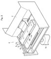
- Fig. 2 is a perspective view showing the flushing unit 4 and Fig. 3 is an exploded perspective view showing the flushing unit 4 in Fig. 2 .
- Fig. 4 is a front view showing the flushing unit 4 in Fig. 2 and Fig. 5 is a cross-sectional view showing the flushing unit 4 which is cut by the "V-V" line in Fig. 4 .
- the flushing unit 4 is structured of a fan 5 and an ink mist collecting mechanism 6.
- the flushing unit 4 is an unit for collecting ink mist generated in a flushing processing in which ink is ejected from a nozzle (not shown) except the time of an image printing at a standby time of the inkjet head "H".
- the fan 5 is a suction mechanism for sucking the ink mist.
- the fan 5 is, for example, a sirocco fan (multi-blade fan) and is disposed on an inner side of a cover part 7 in the printing unit 3.
- the fan 5 is connected with a power source not shown and is always operated regardless of an operation of a flushing processing.
- the ink mist collecting mechanism 6 is a mechanism for collecting ink mist by a suction force of the fan 5.
- the ink mist collecting mechanism 6 is formed in a box-like shape and is closely disposed at a position facing the nozzle faces of the inkjet heads "H” at a standby time when the inkjet heads "H” do not perform an image printing or the like (at a position on the right side of the printing unit 3).
- the ink mist collecting mechanism 6 is provided with an upper face part 8, a tray part 9 and a duct part 10.
- the upper face part 8 is a portion to which inks ejected the nozzles are dropped in the flushing processing.
- the upper face part 8 is provided with a plurality of suction holes 11 (fifteen holes in this embodiment) for sucking ink mist to the inside of the ink mist collecting mechanism 6 by a suction force of the fan 5.
- the plurality of the suction holes 11 is formed in the upper face part 8 along one end part (rear end part) on a side where the fan 5 is arranged. A diameter of the suction hole 11 becomes larger toward both end parts from the center part of the upper face part 8 (see Fig. 4 ).
- the meaning of "larger toward both end parts from the center part of the upper face part 8" includes, as shown in Fig.
- a diameter of a plurality of suction holes 11 having the same diameter may gradually become larger from the center part toward both end parts (in other words, five suction holes 11 disposed at the center part have the same diameter, six suction holes 11 disposed on both sides have respectively the same larger diameter, and four suction holes 11 disposed on further both sides have respectively the same further larger diameter.
- suction holes 11 adjacent to each other may gradually become larger (one by one) from the center part toward both end parts.
- the upper face part 8 is, as shown in Fig. 3 , provided with a droplet forming member 12 at a position corresponding to a plurality of the suction holes 11.
- the droplet forming member 12 is a plate-shaped member for forming ink mist sucked through a plurality of the suction holes 11 into droplets.
- a length dimension of the droplet forming member 12 has a size equivalent to a length dimension of the upper face part 8 and its width dimension is set to be smaller than a width dimension of the upper face part 8 (about 10mm).
- the droplet forming member 12 is, as shown in Fig. 5 , formed in a substantially "L"-shape in its cross section in a widthwise direction.
- the droplet forming member 12 having the structure as described above is, as shown in Fig. 5 , disposed between connection holes 13 (described later) of the tray part 9 and the suction holes 11.
- the droplet forming member 12 is attached on an under side of the suction holes 11 and on a rear end side of the upper face part 8 so that a space "S" which is in communication with the suction holes 11 and is closed on its rear end side (left side in the drawing) and is opened on its front end side (right side in the drawing) is formed between the upper face part 8 and the droplet forming member 12.
- the tray part 9 is a portion which forms a suction passage for ink mist by the fan 5.
- the tray part 9 is formed in a box-like shape having a trapezoid shape in cross section and is provided with an opening part 9a which is opened toward the upper side.
- the opening part 9a is closed by the upper face part 8.
- a plurality of the connection holes 13 is provided at the center portion of the side face 9b in the longitudinal direction of the tray part 9.
- a duct part 10 is connected with the side face 9b of the tray part 9 at a portion corresponding to the connection holes 13 (substantially center part of the tray part 9).
- a bottom face part 9c of the tray part 9 is inclined downward to the rear side.
- One end part (inclined side) of the bottom face part 9c of the tray part 9 is provided with a discharge port (not shown) for discharging the ink which is collected in the tray part 9.
- the duct part 10 is a portion which connects the tray part 9 with the fan 5.
- One end part of the duct part 10 is connected with the side face 9b which corresponds to the connection holes 13 of the tray part 9 as described above.
- the other end part of the duct part 10 is connected with a side face of the cover part 7 which corresponds to a position where the fan 5 is disposed.
- a filter 14 is provided between the fan 5 and the duct part 10.
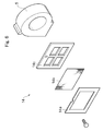
- the filter 14 is, as shown in Fig. 6 , provided with a frame part 14a, a filter part 14b and a fixing part 14c.
- the frame part 14a and the fixing part 14c are, for example, made of metal such as iron, and the filter part 14b is, for example, made of non-woven fabric.
- the filter 14 is structured so that the filter part 14b is sandwiched between the frame part 14a and the fixing part 14c and is fastened, for example, with a screw.
- ink mist is stuck to the filter part 14b to be collected.
- the filter 14b is replaceable.
- the ink mist collecting mechanism 6 having the structure as described above is held so that the upper face part 8 and the nozzle faces of the inkjet heads "H" are separated from each other with a fixed distance (gap space) at the time of a flushing processing. Further, in the flushing unit 4, when the fan 5 is operated, a suction force is generated in a plurality of the suction holes 11 of the upper face part 8 of the ink mist collecting mechanism 6 through the tray part 9 and the duct part 10. Therefore, ink mist occurred by the flushing processing is sucked into the inside of the ink mist collecting mechanism 11 through a plurality of the suction holes 11.
- an ink tray 15 is provided on an under side of the ink mist collecting mechanism 6.
- the ink tray 15 is a portion which stores ink dropped from the upper face part 8 of the ink mist collecting mechanism 6 and the tray part 9.
- a discharge port 15a for discharging stored ink is provided in a bottom face part of the ink tray 15.
- the discharge port 15a is extended to an under side of the printing unit 3 and a valve (not shown) is provided for adjusting discharge of ink in the inside of the ink tray 15.
- a tank 16 is detachably connected with a tip end part of the discharge port 15a. According to this structure, ink which is stored in the ink tray 15 is discharged to the tank 16 through the discharge port 15a by adjusting the valve and is discarded.
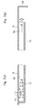
- Figs. 7(a) and 7(b) are views schematically showing airflow generated by the fan 5.
- Figs. 7(a) and 7(b) show only an example and thus a case different from the flow shown in Figs. 7(a) and 7(b) may be occurred according to change of a condition such as a suction force of the fan 5.
- ink mist is sucked through the suction hole 11 by a suction force of the fan 5.
- a flowing speed at a center part is faster than that at an edge part in the suction hole 11 and a relative pressure at the edge part is higher than that at the center part. Therefore, the ink mist is concentrated and coupled to each other at the center part of the suction hole 11 to be formed into a droplet.
- the ink mist sucked through the suction hole 11 is formed into a droplet by being collided with the droplet forming member 12.
- the space between the upper face part 8 and the droplet forming member 12 is set to be narrow (for example, about 4mm), a turbulent flow is occurred between the upper face part 8 and the droplet forming member 12, in other words, in the space "S". Therefore, the ink mist is collided with the upper face part 8 and the droplet forming member 12 and thus the ink mist is formed into a droplet.
- a flow velocity of the ink mist which has been reached to an end part of the droplet forming member 12 is, as shown in Fig. 7(b) , decelerated by the side face 9d (side face opposite to the side face 9b) of the tray part 9. Therefore, since the ink mist stagnates near the side face 9d of the tray part 9, the preceding ink mist and the succeeding ink mist are collided with each other and thus the ink mist is formed into a droplet. Further, the ink mist is collided with the side face 9d of the tray part 9 to be formed into a droplet. The ink mist is formed into droplets in the inside of the ink mist collecting mechanism 6 through the steps as described above.
- the flushing unit 4 is provided with the ink mist collecting mechanism 6 for collecting ink mist by a suction force of the fan 5.
- the ink mist collecting mechanism 6 is provided with the upper face part 8 on which inks ejected from the nozzles are dropped when a flushing processing is performed and in which a plurality of the suction holes 11 is provided for sucking ink mist into the inside of the ink mist collecting mechanism 6 by a suction force of the fan 5 and the droplet forming member 12 for forming the ink mist into droplets.
- ink mist generated when inks are ejected from nozzles of the inkjet heads "H" are collided with the upper face part 8, which is disposed in the vicinity of the inkjet heads "H", and are formed into droplets.
- the ink mist which is not formed into droplets at this time and ink mist generated when the ink is collided with the upper face part 8 are sucked into the inside of the ink mist collecting mechanism 6 through a plurality of the suction holes 11 provided in the upper face part 8 by the fan 5.
- the ink mist sucked into the inside of the ink mist collecting mechanism 6 is formed into droplets by colliding with the droplet forming member 12 provided at the position corresponding to the suction holes 11 and the like.
- the ink mist generated at the time of a flushing processing is immediately formed into droplets after sucked through the suction holes 11 and thus the ink mist is collected at an early stage without being scattered in the printing unit 3 of the inkjet printer 1. Therefore, the ink mist is effectively collected and scattering of the ink mist can be restrained.
- the fan 5 is connected with the side face 9b of the tray part 9 of the ink mist collecting mechanism 6 through the duct part 10 and a plurality of the suction holes 11 is provided along the end part in the upper face part 8 on the side face 9b side of the tray part 9 of the ink mist collecting mechanism 6.
- the droplet forming member 12 is extended from the rear end side (side face 9b side) toward the front end side (side face 9d side) opposite to the rear end side between the connection holes 13 provided in the tray part 9 of the ink mist collecting mechanism 6 to which the fan 5 is connected and the suction holes 11 and the space “S" is formed which is in communication with the suction holes 11 and is closed on its rear end side and is opened on its front end side.
- a flow passage through which the ink mist sucked through the suction holes 11 is reached to the fan 5 can be secured long. Therefore, a colliding area (region) of the ink mist with the droplet forming member 12 and the upper face part 8 is increased in the space "S" and airflow suitable to form the ink mist into droplets is generated and thus the ink mist is further facilitated to be formed into droplets and the ink mist can be collected further effectively.
- the ink mist collecting mechanism 6 is disposed at a position facing the inkjet head "H” at a standby position of the inkjet head “H” and is held so that a distance between the upper face part 8 and the inkjet head “H” is constant and thus the suction force based on the distance between the upper face part 8 and the inkjet head “H” can be made uniform. Therefore, ink mist generated at the time of a flushing processing during a standby time of the inkjet head "H” can be collected surely.
- the filter 14 to which ink mist is stuck is provided between the fan 5 and the duct part 10 of the ink mist collecting mechanism 6. Therefore, the ink mist which is not formed into droplets by the droplet forming member 13 can be surely collected by the filter 14.
- connection holes 13 is provided in the side face 9b of the tray part 9 of the ink mist collecting mechanism 6. Therefore, the ink mist sucked by the fan 5 is formed into droplets by colliding with the portion around the connection holes 13 before reaching to the filter 14. As a result, since the ink mist stuck to the filter 14 can be reduced, the filter part 14b of the filter 14 is not required to be replaced frequently and thus the cost can be reduced.
- the present invention is not limited to the above-mentioned embodiment.
- the droplet forming member 12 is formed in a substantially "L"-shape in cross section and is attached to the back face 8a of the upper face part 8.
- the present invention is not limited to this structure when the space "S" is formed between the upper face part 8 and the droplet forming member 12.
- it may be structured that a plate-shaped member protruding from the side face 9b of the tray part 9 is provided so as to be substantially parallel to the upper face part 8 to form the space "S".
- the fan 5 is used as the suction mechanism but another mechanism may be used.
- the surface on the suction hole side of the droplet forming member 12 may be formed in a projected and recessed structure such as a wave shape or a saw shape. Further, an absorbing body for absorbing ink may be provided on the bottom face part 9c of the tray part 9.
Landscapes
- Ink Jet (AREA)
Abstract
Description
- The present invention relates to a flushing unit which is mounted on an inkjet printer.
- In an inkjet printer, during a standby time when an image printing or the like is not performed on a medium, which is a printing target, it may be occurred that ink is dried or its viscosity is increased in an inside of a nozzle of an inkjet head and, as a result, the nozzle is clogged. In order to prevent this problem, a flushing processing is performed in the inkjet printer, in other words, ink is periodically ejected from a nozzle of an inkjet head for preventing ink from being dried and for preventing its viscosity from being increased.
- When a flushing processing is performed, so-called ink mist which is a fog state ink ejected from the nozzle is generated. The ink mist is easy to be scattered because its particle size is very small and thus the ink mist may stick to the medium, which is a printing target, the inkjet head, the inside of the inkjet printer and the like. Especially, when the mist sticks to a nozzle face of the inkjet head and the mist grows to a lump of ink, image failure such as nozzle's irregular ejection may occur.
- In order to prevent this problem, a mechanism for collecting ink mist has been conventionally provided in an inkjet printer. For example, an inkjet printer described in Patent Literature 1 is provided with an idle ejection receiving part having an adsorbing body for adsorbing ink and a fan. In the inkjet printer, when ink is ejected to the inside of the idle ejection receiving part in a flushing processing, the ejected ink is absorbed by the absorbing body and ink mist having been floated which is generated when the ink is ejected from the nozzle is sucked by the fan to make the ink mist stick to a rear side of the paper and, in this manner, scattering of the ink mist is restrained.
-
- [PTL 1] Japanese Patent Laid-Open No.
2009-101609 - However, the mechanism described in Patent Literature 1 is structured so that the ink mist is stuck to the rear side of the paper and thus, in a case that some trouble occurs in feeding of the paper, the ink mist may be scattered in the inkjet printer. Therefore, the ink mist is not effectively collected.
- In view of the problem described above, an objective of the present invention is to provide a flushing unit which is capable of effectively collecting the ink mist and restraining the scattering of the ink mist.
- In order to attain the above-mentioned objective, the present invention provides a flushing unit which is provided in an inkjet printer on which an inkjet head having a nozzle from which ink is ejected is mounted and which collects ink mist generated at a time of a flushing processing in which ink is ejected from the nozzle. The flushing unit includes a suction mechanism for sucking the ink mist and an ink mist collecting mechanism formed in a box-like shape for collecting the ink mist by a suction force of the suction mechanism. The ink mist collecting mechanism is provided with an upper face part on which the ink ejected from the nozzle is dropped and which is provided with a plurality of suction holes for sucking the ink mist into an inside of the ink mist collecting mechanism by the suction force of the suction mechanism, and a droplet forming member which is provided at a position corresponding to the plurality of the suction holes for forming the ink mist sucked through the plurality of the suction holes into droplets.
- The flushing unit is provided with the box-shaped ink mist collecting mechanism for collecting ink mist by a suction force of the suction mechanism and the ink mist collecting mechanism is provided with the upper face part and the droplet forming member. In this structure, the ink mist generated at the time of a flushing processing is sucked into the inside of the ink mist collecting mechanism by the suction mechanism through a plurality of the suction holes provided in the upper face part. The ink mist which is sucked into the inside of the ink mist collecting mechanism is formed into droplets by being collided with the droplet forming member provided at a position corresponding to the suction holes and the like. As described above, the ink mist generated at the time of a flushing processing is sucked into the inside of the ink mist collecting mechanism to be immediately formed into droplets and thus the ink mist is collected without being scattered in the inside of the inkjet printer. Therefore, the ink mist is effectively collected and scattering of the ink mist is restrained.
- Further, it is preferable that the suction mechanism is connected to one side face side of the ink mist collecting mechanism, the plurality of the suction holes is provided in the upper face part along an end part on the one side face side of the ink mist collecting mechanism, the droplet forming member is disposed between a connection hole of the ink mist collecting mechanism with which the suction mechanism is connected and the suction holes, and a space is formed which is in communication with the suction holes and in which the one side face side is closed and the other side face side facing the one side face side is opened. In this case, a suction flow passage is formed so that, first, ink mist sucked through the suction holes is bent to the other side face side and, after that, the ink mist is bent to the one side face side (suction mechanism side) at the end part of the droplet forming member. Therefore, coupling of the ink mist is occurred in the space which is formed between the upper face part and the droplet forming member due to collision of the ink mist with the droplet forming member and the upper face part, collision of the ink mist with each other, and differences of flow velocities and pressures in the inside of the space. Further, a flow passage through which the ink mist sucked through the suction holes is reached to the suction mechanism can be secured long. Therefore, a colliding area (region) of the ink mist with the droplet forming member and the upper face part is increased in a predetermined space and airflow suitable to form the ink mist into droplets is generated and thus the ink mist is further facilitated to be formed into droplets and is collected further effectively.
- Further, it is preferable that the ink mist collecting mechanism is disposed at a position facing the inkjet head at a standby position of the inkjet head, and the ink mist collecting mechanism is held so that a distance between the upper face part and the inkjet head is constant. In this case, the suction force based on the distance between the upper face part and the inkjet head "H" can be uniformed.
- Further, it is preferable that the suction mechanism is connected with a substantially center part on the one side face side of the ink mist collecting mechanism, and the plurality of the suction holes is formed so that diameters of the suction holes become larger toward both end parts from a center part of the upper face part. A suction force for the ink mist in the suction hole is larger at a position nearer to the suction mechanism. Further, a suction amount through the suction hole becomes larger as its diameter becomes larger. In this embodiment, since the suction mechanism is connected with a substantially center part on the one side face side of the ink mist collecting mechanism and the diameter of the suction hole is set to be larger as the suction hole is separated from the suction mechanism, a suction force for the ink mist in the upper face part can be made uniform.
- Further, it is preferable that a filter to which the ink mist is stuck is provided between the suction mechanism and the ink mist collecting mechanism. In this case, the ink mist which is not formed into droplets by the droplet forming member can be surely collected by the filter.
- Further, it is preferable that a bottom face part of the ink mist collecting mechanism is inclined. In this case, the ink which is formed into droplets by the droplet forming member is accumulated on one end side of the bottom face part of the ink mist collecting mechanism and thus the ink accumulated in the ink mist collecting mechanism can be preferably discharged.
- According to the present invention, the ink mist is collected effectively and scattering of the ink mist is restrained.
-
- [
Fig.1 ]
Fig. 1 is a perspective view showing an outward appearance of an inkjet printer on which a flushing unit is mounted in accordance with an embodiment of the present invention. - [
Fig. 2 ]
Fig. 2 is a perspective view showing a flushing unit. - [
Fig. 3 ]
Fig. 3 is an exploded perspective view showing the flushing unit inFig. 1 . - [
Fig. 4 ]
Fig. 4 is a front view showing the flushing unit inFig. 1 . - [
Fig. 5 ]
Fig. 5 is a cross-sectional view showing the flushing unit which is cut by the "V-V" line inFig. 4 . - [
Fig. 6 ]
Fig. 6 is an exploded perspective view showing a structure of a filter. - [
Fig. 7 ]
Figs. 7(a) and 7(b) are views schematically showing airflow generated by a fan. - An embodiment of a flushing unit in accordance with the present invention will be described in detail below with reference to the accompanying drawings. In the drawings, the same or corresponding portions are indicated with the same reference signs. Further, in the following description, the words such as "upper", "lower", "right", "left", "front" and "rear" correspond to an upper and lower direction, a right and left direction, and a front and rear direction in an inkjet printer.
- A flushing unit in accordance with an embodiment of the present invention is mounted on an inkjet printer.
Fig. 1 is a perspective view showing an outward appearance of an inkjet printer on which a flushing unit is mounted in accordance with an embodiment of the present invention. As shown inFig. 1 , the inkjet printer 1 is, for example, a flat bed type inkjet printer, which is provided with astage part 2 on which a medium to be printed is placed and aprinting unit 3 on which inkjet heads "H" for ejecting ink droplets are mounted. In the inkjet printer 1, aflushing unit 4 is provided on one end side (right side) of theprinting unit 3. - Next, the
flushing unit 4 will be described in detail below.Fig. 2 is a perspective view showing theflushing unit 4 andFig. 3 is an exploded perspective view showing theflushing unit 4 inFig. 2 .Fig. 4 is a front view showing theflushing unit 4 inFig. 2 andFig. 5 is a cross-sectional view showing theflushing unit 4 which is cut by the "V-V" line inFig. 4 . - As shown in
Figs. 2 through 5 , theflushing unit 4 is structured of afan 5 and an inkmist collecting mechanism 6. Theflushing unit 4 is an unit for collecting ink mist generated in a flushing processing in which ink is ejected from a nozzle (not shown) except the time of an image printing at a standby time of the inkjet head "H". - The
fan 5 is a suction mechanism for sucking the ink mist. Thefan 5 is, for example, a sirocco fan (multi-blade fan) and is disposed on an inner side of acover part 7 in theprinting unit 3. Thefan 5 is connected with a power source not shown and is always operated regardless of an operation of a flushing processing. - The ink
mist collecting mechanism 6 is a mechanism for collecting ink mist by a suction force of thefan 5. The inkmist collecting mechanism 6 is formed in a box-like shape and is closely disposed at a position facing the nozzle faces of the inkjet heads "H" at a standby time when the inkjet heads "H" do not perform an image printing or the like (at a position on the right side of the printing unit 3). The inkmist collecting mechanism 6 is provided with anupper face part 8, atray part 9 and aduct part 10. - The
upper face part 8 is a portion to which inks ejected the nozzles are dropped in the flushing processing. Theupper face part 8 is provided with a plurality of suction holes 11 (fifteen holes in this embodiment) for sucking ink mist to the inside of the inkmist collecting mechanism 6 by a suction force of thefan 5. The plurality of the suction holes 11 is formed in theupper face part 8 along one end part (rear end part) on a side where thefan 5 is arranged. A diameter of thesuction hole 11 becomes larger toward both end parts from the center part of the upper face part 8 (seeFig. 4 ). In this embodiment, the meaning of "larger toward both end parts from the center part of theupper face part 8" includes, as shown inFig. 4 , a diameter of a plurality of suction holes 11 having the same diameter may gradually become larger from the center part toward both end parts (in other words, fivesuction holes 11 disposed at the center part have the same diameter, sixsuction holes 11 disposed on both sides have respectively the same larger diameter, and foursuction holes 11 disposed on further both sides have respectively the same further larger diameter. Alternatively, suction holes 11 adjacent to each other may gradually become larger (one by one) from the center part toward both end parts. - Further, the
upper face part 8 is, as shown inFig. 3 , provided with adroplet forming member 12 at a position corresponding to a plurality of the suction holes 11. Thedroplet forming member 12 is a plate-shaped member for forming ink mist sucked through a plurality of the suction holes 11 into droplets. A length dimension of thedroplet forming member 12 has a size equivalent to a length dimension of theupper face part 8 and its width dimension is set to be smaller than a width dimension of the upper face part 8 (about 10mm). Further, thedroplet forming member 12 is, as shown inFig. 5 , formed in a substantially "L"-shape in its cross section in a widthwise direction. Thedroplet forming member 12 having the structure as described above is, as shown inFig. 5 , disposed between connection holes 13 (described later) of thetray part 9 and the suction holes 11. Thedroplet forming member 12 is attached on an under side of the suction holes 11 and on a rear end side of theupper face part 8 so that a space "S" which is in communication with the suction holes 11 and is closed on its rear end side (left side in the drawing) and is opened on its front end side (right side in the drawing) is formed between theupper face part 8 and thedroplet forming member 12. - The
tray part 9 is a portion which forms a suction passage for ink mist by thefan 5. Thetray part 9 is formed in a box-like shape having a trapezoid shape in cross section and is provided with an opening part 9a which is opened toward the upper side. The opening part 9a is closed by theupper face part 8. A plurality of the connection holes 13 is provided at the center portion of theside face 9b in the longitudinal direction of thetray part 9. In addition, aduct part 10 is connected with theside face 9b of thetray part 9 at a portion corresponding to the connection holes 13 (substantially center part of the tray part 9). Further, abottom face part 9c of thetray part 9 is inclined downward to the rear side. One end part (inclined side) of thebottom face part 9c of thetray part 9 is provided with a discharge port (not shown) for discharging the ink which is collected in thetray part 9. - The
duct part 10 is a portion which connects thetray part 9 with thefan 5. One end part of theduct part 10 is connected with theside face 9b which corresponds to the connection holes 13 of thetray part 9 as described above. The other end part of theduct part 10 is connected with a side face of thecover part 7 which corresponds to a position where thefan 5 is disposed. Further, afilter 14 is provided between thefan 5 and theduct part 10. Thefilter 14 is, as shown inFig. 6 , provided with aframe part 14a, afilter part 14b and a fixingpart 14c. Theframe part 14a and the fixingpart 14c are, for example, made of metal such as iron, and thefilter part 14b is, for example, made of non-woven fabric. Thefilter 14 is structured so that thefilter part 14b is sandwiched between theframe part 14a and the fixingpart 14c and is fastened, for example, with a screw. In thefilter 14, ink mist is stuck to thefilter part 14b to be collected. In this embodiment, thefilter 14b is replaceable. - The ink
mist collecting mechanism 6 having the structure as described above is held so that theupper face part 8 and the nozzle faces of the inkjet heads "H" are separated from each other with a fixed distance (gap space) at the time of a flushing processing. Further, in theflushing unit 4, when thefan 5 is operated, a suction force is generated in a plurality of the suction holes 11 of theupper face part 8 of the inkmist collecting mechanism 6 through thetray part 9 and theduct part 10. Therefore, ink mist occurred by the flushing processing is sucked into the inside of the inkmist collecting mechanism 11 through a plurality of the suction holes 11. - Further, an
ink tray 15 is provided on an under side of the inkmist collecting mechanism 6. Theink tray 15 is a portion which stores ink dropped from theupper face part 8 of the inkmist collecting mechanism 6 and thetray part 9. Adischarge port 15a for discharging stored ink is provided in a bottom face part of theink tray 15. Thedischarge port 15a is extended to an under side of theprinting unit 3 and a valve (not shown) is provided for adjusting discharge of ink in the inside of theink tray 15. Further, atank 16 is detachably connected with a tip end part of thedischarge port 15a. According to this structure, ink which is stored in theink tray 15 is discharged to thetank 16 through thedischarge port 15a by adjusting the valve and is discarded. - Next, a step in which ink mist is formed into droplets in the ink
mist collecting mechanism 6 will be described below with reference toFig. 7. Figs. 7(a) and 7(b) are views schematically showing airflow generated by thefan 5. However,Figs. 7(a) and 7(b) show only an example and thus a case different from the flow shown inFigs. 7(a) and 7(b) may be occurred according to change of a condition such as a suction force of thefan 5. - As shown in
Fig. 7(a) , first, ink mist is sucked through thesuction hole 11 by a suction force of thefan 5. In this case, a flowing speed at a center part is faster than that at an edge part in thesuction hole 11 and a relative pressure at the edge part is higher than that at the center part. Therefore, the ink mist is concentrated and coupled to each other at the center part of thesuction hole 11 to be formed into a droplet. In addition, the ink mist sucked through thesuction hole 11 is formed into a droplet by being collided with thedroplet forming member 12. - Further, when the ink mist is sucked through the
suction hole 11, a vortex flow swirling upward is occurred on aback face 8a side of theupper face part 8 in the vicinity of the edge part of thesuction hole 11. As a result, the ink mist is collided with theback face 8a of theupper face part 8 and thus the ink mist is formed into a droplet. - In addition, in the space "S" formed by the
back face 8a of theupper face part 8 and thedroplet forming member 12, a speed at the center part becomes faster than those on both side face sides and relative pressures on both side face sides become higher than that at the center part. As a result, the ink mist advancing the space "S" which is sucked through thesuction hole 11 and is bent to the opened side (right side in the drawing) by thedroplet forming member 12 is concentrated and coupled to each other at the center part of the space "S". The coupled ink mist is dropped downward by its own weight and is collided with thedroplet forming member 12 to be formed into a droplet. Further, since the space between theupper face part 8 and thedroplet forming member 12 is set to be narrow (for example, about 4mm), a turbulent flow is occurred between theupper face part 8 and thedroplet forming member 12, in other words, in the space "S". Therefore, the ink mist is collided with theupper face part 8 and thedroplet forming member 12 and thus the ink mist is formed into a droplet. - A flow velocity of the ink mist which has been reached to an end part of the
droplet forming member 12 is, as shown inFig. 7(b) , decelerated by theside face 9d (side face opposite to theside face 9b) of thetray part 9. Therefore, since the ink mist stagnates near theside face 9d of thetray part 9, the preceding ink mist and the succeeding ink mist are collided with each other and thus the ink mist is formed into a droplet. Further, the ink mist is collided with theside face 9d of thetray part 9 to be formed into a droplet. The ink mist is formed into droplets in the inside of the inkmist collecting mechanism 6 through the steps as described above. - As described above, the
flushing unit 4 is provided with the inkmist collecting mechanism 6 for collecting ink mist by a suction force of thefan 5. The inkmist collecting mechanism 6 is provided with theupper face part 8 on which inks ejected from the nozzles are dropped when a flushing processing is performed and in which a plurality of the suction holes 11 is provided for sucking ink mist into the inside of the inkmist collecting mechanism 6 by a suction force of thefan 5 and thedroplet forming member 12 for forming the ink mist into droplets. - In the structure as described above, first, ink mist generated when inks are ejected from nozzles of the inkjet heads "H" are collided with the
upper face part 8, which is disposed in the vicinity of the inkjet heads "H", and are formed into droplets. The ink mist which is not formed into droplets at this time and ink mist generated when the ink is collided with theupper face part 8 are sucked into the inside of the inkmist collecting mechanism 6 through a plurality of the suction holes 11 provided in theupper face part 8 by thefan 5. The ink mist sucked into the inside of the inkmist collecting mechanism 6 is formed into droplets by colliding with thedroplet forming member 12 provided at the position corresponding to the suction holes 11 and the like. As described above, the ink mist generated at the time of a flushing processing is immediately formed into droplets after sucked through the suction holes 11 and thus the ink mist is collected at an early stage without being scattered in theprinting unit 3 of the inkjet printer 1. Therefore, the ink mist is effectively collected and scattering of the ink mist can be restrained. - Further, in this embodiment, the
fan 5 is connected with theside face 9b of thetray part 9 of the inkmist collecting mechanism 6 through theduct part 10 and a plurality of the suction holes 11 is provided along the end part in theupper face part 8 on theside face 9b side of thetray part 9 of the inkmist collecting mechanism 6. Further, thedroplet forming member 12 is extended from the rear end side (side face 9b side) toward the front end side (side face 9d side) opposite to the rear end side between the connection holes 13 provided in thetray part 9 of the inkmist collecting mechanism 6 to which thefan 5 is connected and the suction holes 11 and the space "S" is formed which is in communication with the suction holes 11 and is closed on its rear end side and is opened on its front end side. - When this structure is adopted, a suction flow passage is formed so that, first, the ink mist sucked through the suction holes 11 is bent to the
side face 9d side and, after that, the ink mist is bent to thefan 5 side at the end part on the front end side of thedroplet forming member 12. As a result, as shown inFigs. 7(a) and 7(b) , coupling of the ink mist is occurred in the space "S", which is formed between theupper face part 8 and thedroplet forming member 12, due to collision of the ink mist with thedroplet forming member 12 and theupper face part 8, collision of the ink mist with each other, and differences of flow velocities and pressures in the inside of the space "S". Further, a flow passage through which the ink mist sucked through the suction holes 11 is reached to thefan 5 can be secured long. Therefore, a colliding area (region) of the ink mist with thedroplet forming member 12 and theupper face part 8 is increased in the space "S" and airflow suitable to form the ink mist into droplets is generated and thus the ink mist is further facilitated to be formed into droplets and the ink mist can be collected further effectively. - Further, the ink
mist collecting mechanism 6 is disposed at a position facing the inkjet head "H" at a standby position of the inkjet head "H" and is held so that a distance between theupper face part 8 and the inkjet head "H" is constant and thus the suction force based on the distance between theupper face part 8 and the inkjet head "H" can be made uniform. Therefore, ink mist generated at the time of a flushing processing during a standby time of the inkjet head "H" can be collected surely. - Further, the
filter 14 to which ink mist is stuck is provided between thefan 5 and theduct part 10 of the inkmist collecting mechanism 6. Therefore, the ink mist which is not formed into droplets by thedroplet forming member 13 can be surely collected by thefilter 14. - In this embodiment, a plurality of the connection holes 13 is provided in the
side face 9b of thetray part 9 of the inkmist collecting mechanism 6. Therefore, the ink mist sucked by thefan 5 is formed into droplets by colliding with the portion around the connection holes 13 before reaching to thefilter 14. As a result, since the ink mist stuck to thefilter 14 can be reduced, thefilter part 14b of thefilter 14 is not required to be replaced frequently and thus the cost can be reduced. - The present invention is not limited to the above-mentioned embodiment. For example, in the embodiment described above, the
droplet forming member 12 is formed in a substantially "L"-shape in cross section and is attached to theback face 8a of theupper face part 8. However, the present invention is not limited to this structure when the space "S" is formed between theupper face part 8 and thedroplet forming member 12. For example, it may be structured that a plate-shaped member protruding from theside face 9b of thetray part 9 is provided so as to be substantially parallel to theupper face part 8 to form the space "S". - Further, in the embodiment described above, the
fan 5 is used as the suction mechanism but another mechanism may be used. - Further, in addition to the embodiment described above, the surface on the suction hole side of the
droplet forming member 12 may be formed in a projected and recessed structure such as a wave shape or a saw shape. Further, an absorbing body for absorbing ink may be provided on thebottom face part 9c of thetray part 9. - 1 ... inkjet printer, 4 ... flushing unit, 5 ... fan (suction mechanism), 6 ... ink mist collecting mechanism, 8 ... upper face part, 11 ... suction hole, 12 ... droplet forming member, "H" ... inkjet head, "S" ... space.
Claims (6)
- A flushing unit which is provided in an inkjet printer on which an inkjet head having a nozzle from which ink is ejected is mounted and which collects ink mist that is generated at a time of a flushing processing in which ink is ejected from the nozzle, the flushing unit comprising:a suction mechanism for sucking the ink mist; andan ink mist collecting mechanism for collecting the ink mist by a suction force of the suction mechanism, the ink mist collecting mechanism being formed in a box-like shape;wherein the ink mist collecting mechanism is provided with:an upper face part on which the ink ejected from the nozzle is dropped and which is provided with a plurality of suction holes for sucking the ink mist into an inside of the ink mist collecting mechanism by the suction force of the suction mechanism; anda droplet forming member which is provided at a position corresponding to the plurality of the suction holes for forming the ink mist sucked through the plurality of the suction holes into droplets.
- The flushing unit according to claim 1, wherein
the suction mechanism is connected to one side face side of the ink mist collecting mechanism,
the plurality of the suction holes is provided in the upper face part along an end part on the one side face side of the ink mist collecting mechanism,
the droplet forming member is disposed between a connection hole of the ink mist collecting mechanism with which the suction mechanism is connected and the suction holes, and
a space is formed which is in communication with the suction holes and in which the one side face side is closed and an other side face side facing the one side face side is opened. - The flushing unit according to claim 1 or 2, wherein the ink mist collecting mechanism is disposed at a position facing the inkjet head at a standby position of the inkjet head, and the ink mist collecting mechanism is held so that a distance between the upper face part and the inkjet head is constant.
- The flushing unit according to one of claims 1 through 3, wherein
the suction mechanism is connected with a substantially center part on the one side face side of the ink mist collecting mechanism, and
the plurality of the suction holes is formed so that diameters of the suction holes become larger toward both end parts from a center part of the upper face part. - The flushing unit according to one of claims 1 through 4, wherein a filter to which the ink mist is stuck is provided between the suction mechanism and the ink mist collecting mechanism.
- The flushing unit according to one of claims 1 through 5, wherein a bottom face part of the ink mist collecting mechanism is inclined.
Applications Claiming Priority (2)
| Application Number | Priority Date | Filing Date | Title |
|---|---|---|---|
| JP2009165707A JP5144600B2 (en) | 2009-07-14 | 2009-07-14 | Flushing unit |
| PCT/JP2010/057899 WO2011007611A1 (en) | 2009-07-14 | 2010-05-10 | Flushing unit |
Publications (3)
| Publication Number | Publication Date |
|---|---|
| EP2455223A1 true EP2455223A1 (en) | 2012-05-23 |
| EP2455223A4 EP2455223A4 (en) | 2013-03-06 |
| EP2455223B1 EP2455223B1 (en) | 2015-03-04 |
Family
ID=43449221
Family Applications (1)
| Application Number | Title | Priority Date | Filing Date |
|---|---|---|---|
| EP10799673.8A Not-in-force EP2455223B1 (en) | 2009-07-14 | 2010-05-10 | Flushing unit |
Country Status (6)
| Country | Link |
|---|---|
| US (1) | US8388103B2 (en) |
| EP (1) | EP2455223B1 (en) |
| JP (1) | JP5144600B2 (en) |
| KR (1) | KR101331568B1 (en) |
| CN (1) | CN102548767B (en) |
| WO (1) | WO2011007611A1 (en) |
Families Citing this family (12)
| Publication number | Priority date | Publication date | Assignee | Title |
|---|---|---|---|---|
| JP6171486B2 (en) * | 2013-03-29 | 2017-08-02 | セイコーエプソン株式会社 | Liquid ejection device |
| JP6368565B2 (en) * | 2014-07-07 | 2018-08-01 | 株式会社ミマキエンジニアリング | Inkjet recording apparatus and inkjet recording method |
| CN104401130B (en) * | 2014-11-28 | 2016-05-25 | 杭州宏华数码科技股份有限公司 | The floating black cleaning plant of ink-jet decorating machine |
| CN104401131A (en) * | 2014-11-28 | 2015-03-11 | 杭州宏华数码科技股份有限公司 | Floating ink cleaning device for continuous conduction band inkjet printing machine |
| JP6575106B2 (en) * | 2015-03-30 | 2019-09-18 | セイコーエプソン株式会社 | Printing apparatus and liquid discharge control method |
| JP6613614B2 (en) * | 2015-05-19 | 2019-12-04 | セイコーエプソン株式会社 | Liquid ejection device |
| JP6694353B2 (en) * | 2016-08-24 | 2020-05-13 | 株式会社ミマキエンジニアリング | inkjet printer |
| JP6921635B2 (en) * | 2017-06-13 | 2021-08-18 | キヤノン株式会社 | Inkjet equipment and mist collection equipment |
| JP2020059230A (en) * | 2018-10-11 | 2020-04-16 | コニカミノルタ株式会社 | Ink jet recording apparatus |
| JP7250559B2 (en) * | 2019-02-20 | 2023-04-03 | 理想科学工業株式会社 | Liquid mist collection device |
| KR20220033575A (en) * | 2020-09-07 | 2022-03-17 | 삼성디스플레이 주식회사 | Cleaning apparatus and cleaning method using the same |
| JP7753775B2 (en) * | 2020-10-27 | 2025-10-15 | ブラザー工業株式会社 | printing device |
Family Cites Families (10)
| Publication number | Priority date | Publication date | Assignee | Title |
|---|---|---|---|---|
| JP3255528B2 (en) * | 1993-12-30 | 2002-02-12 | キヤノン株式会社 | Ink jet device |
| US6312092B1 (en) * | 1997-03-25 | 2001-11-06 | Seiko Epson Corporation | Ink jet recording apparatus and ink suction method of the recording head |
| JP2000229423A (en) * | 1999-02-12 | 2000-08-22 | Canon Inc | Exhaust system for recording device |
| JP2002187261A (en) | 2000-10-10 | 2002-07-02 | Canon Inc | Ink jet recording device |
| CN1317128C (en) * | 2002-07-26 | 2007-05-23 | 兄弟工业株式会社 | Inkjet recording equipment |
| US7357479B2 (en) * | 2004-10-29 | 2008-04-15 | Hewlett-Packard Development, L.P. | Aerosol extraction during printing by and servicing of fluid ejection-device |
| JP4948146B2 (en) * | 2006-12-15 | 2012-06-06 | キヤノン株式会社 | Inkjet recording device |
| JP2008229966A (en) * | 2007-03-19 | 2008-10-02 | Canon Inc | Inkjet recording device |
| JP2009101609A (en) * | 2007-10-24 | 2009-05-14 | Ricoh Co Ltd | Image forming apparatus |
| JP2009229423A (en) | 2008-03-25 | 2009-10-08 | Kobe Steel Ltd | Near-field probe and electrical characteristic measuring instrument equipped with the same |
-
2009
- 2009-07-14 JP JP2009165707A patent/JP5144600B2/en active Active
-
2010
- 2010-05-10 CN CN201080040955.XA patent/CN102548767B/en not_active Expired - Fee Related
- 2010-05-10 KR KR1020127001070A patent/KR101331568B1/en not_active Expired - Fee Related
- 2010-05-10 WO PCT/JP2010/057899 patent/WO2011007611A1/en not_active Ceased
- 2010-05-10 EP EP10799673.8A patent/EP2455223B1/en not_active Not-in-force
-
2012
- 2012-01-12 US US13/349,001 patent/US8388103B2/en not_active Expired - Fee Related
Also Published As
| Publication number | Publication date |
|---|---|
| US20120113187A1 (en) | 2012-05-10 |
| JP5144600B2 (en) | 2013-02-13 |
| KR101331568B1 (en) | 2013-11-20 |
| CN102548767B (en) | 2014-10-22 |
| WO2011007611A1 (en) | 2011-01-20 |
| KR20120032526A (en) | 2012-04-05 |
| US8388103B2 (en) | 2013-03-05 |
| EP2455223A4 (en) | 2013-03-06 |
| JP2011020301A (en) | 2011-02-03 |
| CN102548767A (en) | 2012-07-04 |
| EP2455223B1 (en) | 2015-03-04 |
Similar Documents
| Publication | Publication Date | Title |
|---|---|---|
| EP2455223B1 (en) | Flushing unit | |
| US9498962B2 (en) | Printing device | |
| JP3781284B2 (en) | Inkjet recording head and recording apparatus therefor | |
| US20140321878A1 (en) | Image forming apparatus and exhaust duct | |
| JP5112173B2 (en) | Inkjet printer and ink mist liquefaction member | |
| CN104275940B (en) | One flies black gathering-device and ink-jet printer | |
| JP4018577B2 (en) | Inkjet recording head cartridge | |
| US8342641B2 (en) | Ink separators | |
| JP5778531B2 (en) | Inkjet printer, ink recovery member, and ink recovery method | |
| JP6776031B2 (en) | Inkjet device and mist collection method | |
| JP2020157581A (en) | Inkjet printing equipment | |
| JP6024440B2 (en) | Empty discharge receiver and image forming apparatus | |
| CN110621507B9 (en) | Mist extraction system for ink jet printer | |
| JP5994616B2 (en) | Empty discharge receiver and image forming apparatus | |
| JP5087682B2 (en) | Parts for injecting fluid | |
| US6832829B2 (en) | Ink jet aerosol control using carrier movement as a piston pump | |
| JP2020059230A (en) | Ink jet recording apparatus | |
| JP2017105028A (en) | Recording device | |
| JP4071206B2 (en) | Image forming apparatus | |
| JP2004284058A (en) | Ink jet recorder | |
| JP7047308B2 (en) | Printing equipment | |
| JPS591800Y2 (en) | Inkjet printer deflection electrode | |
| JP2004025718A (en) | Image forming device | |
| JP6070028B2 (en) | Image forming apparatus | |
| CN120229008A (en) | A nozzle maintenance device for air-ink separation |
Legal Events
| Date | Code | Title | Description |
|---|---|---|---|
| PUAI | Public reference made under article 153(3) epc to a published international application that has entered the european phase |
Free format text: ORIGINAL CODE: 0009012 |
|
| 17P | Request for examination filed |
Effective date: 20120104 |
|
| AK | Designated contracting states |
Kind code of ref document: A1 Designated state(s): AL AT BE BG CH CY CZ DE DK EE ES FI FR GB GR HR HU IE IS IT LI LT LU LV MC MK MT NL NO PL PT RO SE SI SK SM TR |
|
| DAX | Request for extension of the european patent (deleted) | ||
| A4 | Supplementary search report drawn up and despatched |
Effective date: 20130201 |
|
| RIC1 | Information provided on ipc code assigned before grant |
Ipc: B41J 2/175 20060101ALI20130128BHEP Ipc: B41J 2/165 20060101ALI20130128BHEP Ipc: B41J 2/18 20060101AFI20130128BHEP Ipc: B41J 2/17 20060101ALI20130128BHEP Ipc: B41J 2/185 20060101ALI20130128BHEP |
|
| 17Q | First examination report despatched |
Effective date: 20131010 |
|
| GRAP | Despatch of communication of intention to grant a patent |
Free format text: ORIGINAL CODE: EPIDOSNIGR1 |
|
| INTG | Intention to grant announced |
Effective date: 20141013 |
|
| GRAS | Grant fee paid |
Free format text: ORIGINAL CODE: EPIDOSNIGR3 |
|
| GRAA | (expected) grant |
Free format text: ORIGINAL CODE: 0009210 |
|
| AK | Designated contracting states |
Kind code of ref document: B1 Designated state(s): AL AT BE BG CH CY CZ DE DK EE ES FI FR GB GR HR HU IE IS IT LI LT LU LV MC MK MT NL NO PL PT RO SE SI SK SM TR |
|
| REG | Reference to a national code |
Ref country code: GB Ref legal event code: FG4D |
|
| REG | Reference to a national code |
Ref country code: CH Ref legal event code: EP |
|
| REG | Reference to a national code |
Ref country code: IE Ref legal event code: FG4D |
|
| REG | Reference to a national code |
Ref country code: AT Ref legal event code: REF Ref document number: 713487 Country of ref document: AT Kind code of ref document: T Effective date: 20150415 |
|
| REG | Reference to a national code |
Ref country code: DE Ref legal event code: R096 Ref document number: 602010022901 Country of ref document: DE Effective date: 20150416 |
|
| REG | Reference to a national code |
Ref country code: AT Ref legal event code: MK05 Ref document number: 713487 Country of ref document: AT Kind code of ref document: T Effective date: 20150304 Ref country code: NL Ref legal event code: VDEP Effective date: 20150304 |
|
| PG25 | Lapsed in a contracting state [announced via postgrant information from national office to epo] |
Ref country code: FI Free format text: LAPSE BECAUSE OF FAILURE TO SUBMIT A TRANSLATION OF THE DESCRIPTION OR TO PAY THE FEE WITHIN THE PRESCRIBED TIME-LIMIT Effective date: 20150304 Ref country code: NO Free format text: LAPSE BECAUSE OF FAILURE TO SUBMIT A TRANSLATION OF THE DESCRIPTION OR TO PAY THE FEE WITHIN THE PRESCRIBED TIME-LIMIT Effective date: 20150604 Ref country code: LT Free format text: LAPSE BECAUSE OF FAILURE TO SUBMIT A TRANSLATION OF THE DESCRIPTION OR TO PAY THE FEE WITHIN THE PRESCRIBED TIME-LIMIT Effective date: 20150304 Ref country code: HR Free format text: LAPSE BECAUSE OF FAILURE TO SUBMIT A TRANSLATION OF THE DESCRIPTION OR TO PAY THE FEE WITHIN THE PRESCRIBED TIME-LIMIT Effective date: 20150304 Ref country code: ES Free format text: LAPSE BECAUSE OF FAILURE TO SUBMIT A TRANSLATION OF THE DESCRIPTION OR TO PAY THE FEE WITHIN THE PRESCRIBED TIME-LIMIT Effective date: 20150304 Ref country code: SE Free format text: LAPSE BECAUSE OF FAILURE TO SUBMIT A TRANSLATION OF THE DESCRIPTION OR TO PAY THE FEE WITHIN THE PRESCRIBED TIME-LIMIT Effective date: 20150304 |
|
| REG | Reference to a national code |
Ref country code: LT Ref legal event code: MG4D |
|
| PG25 | Lapsed in a contracting state [announced via postgrant information from national office to epo] |
Ref country code: GR Free format text: LAPSE BECAUSE OF FAILURE TO SUBMIT A TRANSLATION OF THE DESCRIPTION OR TO PAY THE FEE WITHIN THE PRESCRIBED TIME-LIMIT Effective date: 20150605 Ref country code: AT Free format text: LAPSE BECAUSE OF FAILURE TO SUBMIT A TRANSLATION OF THE DESCRIPTION OR TO PAY THE FEE WITHIN THE PRESCRIBED TIME-LIMIT Effective date: 20150304 Ref country code: LV Free format text: LAPSE BECAUSE OF FAILURE TO SUBMIT A TRANSLATION OF THE DESCRIPTION OR TO PAY THE FEE WITHIN THE PRESCRIBED TIME-LIMIT Effective date: 20150304 |
|
| PG25 | Lapsed in a contracting state [announced via postgrant information from national office to epo] |
Ref country code: NL Free format text: LAPSE BECAUSE OF FAILURE TO SUBMIT A TRANSLATION OF THE DESCRIPTION OR TO PAY THE FEE WITHIN THE PRESCRIBED TIME-LIMIT Effective date: 20150304 |
|
| PG25 | Lapsed in a contracting state [announced via postgrant information from national office to epo] |
Ref country code: PT Free format text: LAPSE BECAUSE OF FAILURE TO SUBMIT A TRANSLATION OF THE DESCRIPTION OR TO PAY THE FEE WITHIN THE PRESCRIBED TIME-LIMIT Effective date: 20150706 Ref country code: CZ Free format text: LAPSE BECAUSE OF FAILURE TO SUBMIT A TRANSLATION OF THE DESCRIPTION OR TO PAY THE FEE WITHIN THE PRESCRIBED TIME-LIMIT Effective date: 20150304 Ref country code: SK Free format text: LAPSE BECAUSE OF FAILURE TO SUBMIT A TRANSLATION OF THE DESCRIPTION OR TO PAY THE FEE WITHIN THE PRESCRIBED TIME-LIMIT Effective date: 20150304 Ref country code: RO Free format text: LAPSE BECAUSE OF FAILURE TO SUBMIT A TRANSLATION OF THE DESCRIPTION OR TO PAY THE FEE WITHIN THE PRESCRIBED TIME-LIMIT Effective date: 20150304 Ref country code: EE Free format text: LAPSE BECAUSE OF FAILURE TO SUBMIT A TRANSLATION OF THE DESCRIPTION OR TO PAY THE FEE WITHIN THE PRESCRIBED TIME-LIMIT Effective date: 20150304 |
|
| PG25 | Lapsed in a contracting state [announced via postgrant information from national office to epo] |
Ref country code: PL Free format text: LAPSE BECAUSE OF FAILURE TO SUBMIT A TRANSLATION OF THE DESCRIPTION OR TO PAY THE FEE WITHIN THE PRESCRIBED TIME-LIMIT Effective date: 20150304 Ref country code: IS Free format text: LAPSE BECAUSE OF FAILURE TO SUBMIT A TRANSLATION OF THE DESCRIPTION OR TO PAY THE FEE WITHIN THE PRESCRIBED TIME-LIMIT Effective date: 20150704 |
|
| REG | Reference to a national code |
Ref country code: DE Ref legal event code: R097 Ref document number: 602010022901 Country of ref document: DE |
|
| PG25 | Lapsed in a contracting state [announced via postgrant information from national office to epo] |
Ref country code: IT Free format text: LAPSE BECAUSE OF FAILURE TO SUBMIT A TRANSLATION OF THE DESCRIPTION OR TO PAY THE FEE WITHIN THE PRESCRIBED TIME-LIMIT Effective date: 20150304 |
|
| REG | Reference to a national code |
Ref country code: CH Ref legal event code: PL |
|
| PLBE | No opposition filed within time limit |
Free format text: ORIGINAL CODE: 0009261 |
|
| STAA | Information on the status of an ep patent application or granted ep patent |
Free format text: STATUS: NO OPPOSITION FILED WITHIN TIME LIMIT |
|
| PG25 | Lapsed in a contracting state [announced via postgrant information from national office to epo] |
Ref country code: LU Free format text: LAPSE BECAUSE OF FAILURE TO SUBMIT A TRANSLATION OF THE DESCRIPTION OR TO PAY THE FEE WITHIN THE PRESCRIBED TIME-LIMIT Effective date: 20150510 Ref country code: MC Free format text: LAPSE BECAUSE OF FAILURE TO SUBMIT A TRANSLATION OF THE DESCRIPTION OR TO PAY THE FEE WITHIN THE PRESCRIBED TIME-LIMIT Effective date: 20150304 Ref country code: LI Free format text: LAPSE BECAUSE OF NON-PAYMENT OF DUE FEES Effective date: 20150531 Ref country code: CH Free format text: LAPSE BECAUSE OF NON-PAYMENT OF DUE FEES Effective date: 20150531 Ref country code: DK Free format text: LAPSE BECAUSE OF FAILURE TO SUBMIT A TRANSLATION OF THE DESCRIPTION OR TO PAY THE FEE WITHIN THE PRESCRIBED TIME-LIMIT Effective date: 20150304 |
|
| 26N | No opposition filed |
Effective date: 20151207 |
|
| REG | Reference to a national code |
Ref country code: IE Ref legal event code: MM4A |
|
| PG25 | Lapsed in a contracting state [announced via postgrant information from national office to epo] |
Ref country code: SI Free format text: LAPSE BECAUSE OF FAILURE TO SUBMIT A TRANSLATION OF THE DESCRIPTION OR TO PAY THE FEE WITHIN THE PRESCRIBED TIME-LIMIT Effective date: 20150304 |
|
| REG | Reference to a national code |
Ref country code: FR Ref legal event code: PLFP Year of fee payment: 7 |
|
| PG25 | Lapsed in a contracting state [announced via postgrant information from national office to epo] |
Ref country code: IE Free format text: LAPSE BECAUSE OF NON-PAYMENT OF DUE FEES Effective date: 20150510 |
|
| PG25 | Lapsed in a contracting state [announced via postgrant information from national office to epo] |
Ref country code: BE Free format text: LAPSE BECAUSE OF FAILURE TO SUBMIT A TRANSLATION OF THE DESCRIPTION OR TO PAY THE FEE WITHIN THE PRESCRIBED TIME-LIMIT Effective date: 20150304 |
|
| PG25 | Lapsed in a contracting state [announced via postgrant information from national office to epo] |
Ref country code: MT Free format text: LAPSE BECAUSE OF FAILURE TO SUBMIT A TRANSLATION OF THE DESCRIPTION OR TO PAY THE FEE WITHIN THE PRESCRIBED TIME-LIMIT Effective date: 20150304 |
|
| REG | Reference to a national code |
Ref country code: FR Ref legal event code: PLFP Year of fee payment: 8 |
|
| PG25 | Lapsed in a contracting state [announced via postgrant information from national office to epo] |
Ref country code: BG Free format text: LAPSE BECAUSE OF FAILURE TO SUBMIT A TRANSLATION OF THE DESCRIPTION OR TO PAY THE FEE WITHIN THE PRESCRIBED TIME-LIMIT Effective date: 20150304 Ref country code: SM Free format text: LAPSE BECAUSE OF FAILURE TO SUBMIT A TRANSLATION OF THE DESCRIPTION OR TO PAY THE FEE WITHIN THE PRESCRIBED TIME-LIMIT Effective date: 20150304 Ref country code: HU Free format text: LAPSE BECAUSE OF FAILURE TO SUBMIT A TRANSLATION OF THE DESCRIPTION OR TO PAY THE FEE WITHIN THE PRESCRIBED TIME-LIMIT; INVALID AB INITIO Effective date: 20100510 |
|
| PG25 | Lapsed in a contracting state [announced via postgrant information from national office to epo] |
Ref country code: CY Free format text: LAPSE BECAUSE OF FAILURE TO SUBMIT A TRANSLATION OF THE DESCRIPTION OR TO PAY THE FEE WITHIN THE PRESCRIBED TIME-LIMIT Effective date: 20150304 |
|
| PG25 | Lapsed in a contracting state [announced via postgrant information from national office to epo] |
Ref country code: TR Free format text: LAPSE BECAUSE OF FAILURE TO SUBMIT A TRANSLATION OF THE DESCRIPTION OR TO PAY THE FEE WITHIN THE PRESCRIBED TIME-LIMIT Effective date: 20150304 |
|
| REG | Reference to a national code |
Ref country code: FR Ref legal event code: PLFP Year of fee payment: 9 |
|
| PG25 | Lapsed in a contracting state [announced via postgrant information from national office to epo] |
Ref country code: MK Free format text: LAPSE BECAUSE OF FAILURE TO SUBMIT A TRANSLATION OF THE DESCRIPTION OR TO PAY THE FEE WITHIN THE PRESCRIBED TIME-LIMIT Effective date: 20150304 |
|
| PG25 | Lapsed in a contracting state [announced via postgrant information from national office to epo] |
Ref country code: AL Free format text: LAPSE BECAUSE OF FAILURE TO SUBMIT A TRANSLATION OF THE DESCRIPTION OR TO PAY THE FEE WITHIN THE PRESCRIBED TIME-LIMIT Effective date: 20150304 |
|
| PGFP | Annual fee paid to national office [announced via postgrant information from national office to epo] |
Ref country code: GB Payment date: 20220401 Year of fee payment: 13 Ref country code: FR Payment date: 20220408 Year of fee payment: 13 |
|
| GBPC | Gb: european patent ceased through non-payment of renewal fee |
Effective date: 20230510 |
|
| PG25 | Lapsed in a contracting state [announced via postgrant information from national office to epo] |
Ref country code: GB Free format text: LAPSE BECAUSE OF NON-PAYMENT OF DUE FEES Effective date: 20230510 |
|
| PG25 | Lapsed in a contracting state [announced via postgrant information from national office to epo] |
Ref country code: FR Free format text: LAPSE BECAUSE OF NON-PAYMENT OF DUE FEES Effective date: 20230531 |
|
| PGFP | Annual fee paid to national office [announced via postgrant information from national office to epo] |
Ref country code: DE Payment date: 20240328 Year of fee payment: 15 |
|
| REG | Reference to a national code |
Ref country code: DE Ref legal event code: R119 Ref document number: 602010022901 Country of ref document: DE |
|
| PG25 | Lapsed in a contracting state [announced via postgrant information from national office to epo] |
Ref country code: DE Free format text: LAPSE BECAUSE OF NON-PAYMENT OF DUE FEES Effective date: 20251202 |