EP2455050A2 - Lifting device with distributed-sensing scale - Google Patents
Lifting device with distributed-sensing scale Download PDFInfo
- Publication number
- EP2455050A2 EP2455050A2 EP11189047A EP11189047A EP2455050A2 EP 2455050 A2 EP2455050 A2 EP 2455050A2 EP 11189047 A EP11189047 A EP 11189047A EP 11189047 A EP11189047 A EP 11189047A EP 2455050 A2 EP2455050 A2 EP 2455050A2
- Authority
- EP
- European Patent Office
- Prior art keywords
- actuator
- lifting arm
- pivot
- torque
- lifting device
- Prior art date
- Legal status (The legal status is an assumption and is not a legal conclusion. Google has not performed a legal analysis and makes no representation as to the accuracy of the status listed.)
- Withdrawn
Links
- 238000006073 displacement reaction Methods 0.000 claims abstract description 28
- 238000005452 bending Methods 0.000 description 5
- 238000005303 weighing Methods 0.000 description 5
- 230000003071 parasitic effect Effects 0.000 description 3
- 230000003068 static effect Effects 0.000 description 3
- 235000004443 Ricinus communis Nutrition 0.000 description 2
- 230000009286 beneficial effect Effects 0.000 description 2
- 238000010276 construction Methods 0.000 description 1
- 230000003247 decreasing effect Effects 0.000 description 1
- 230000001627 detrimental effect Effects 0.000 description 1
- 230000005489 elastic deformation Effects 0.000 description 1
- 238000005259 measurement Methods 0.000 description 1
- 238000012986 modification Methods 0.000 description 1
- 230000004048 modification Effects 0.000 description 1
- 230000035945 sensitivity Effects 0.000 description 1
Images


Classifications
-
- A—HUMAN NECESSITIES
- A61—MEDICAL OR VETERINARY SCIENCE; HYGIENE
- A61G—TRANSPORT, PERSONAL CONVEYANCES, OR ACCOMMODATION SPECIALLY ADAPTED FOR PATIENTS OR DISABLED PERSONS; OPERATING TABLES OR CHAIRS; CHAIRS FOR DENTISTRY; FUNERAL DEVICES
- A61G7/00—Beds specially adapted for nursing; Devices for lifting patients or disabled persons
- A61G7/10—Devices for lifting patients or disabled persons, e.g. special adaptations of hoists thereto
- A61G7/1013—Lifting of patients by
- A61G7/1017—Pivoting arms, e.g. crane type mechanisms
-
- A—HUMAN NECESSITIES
- A61—MEDICAL OR VETERINARY SCIENCE; HYGIENE
- A61G—TRANSPORT, PERSONAL CONVEYANCES, OR ACCOMMODATION SPECIALLY ADAPTED FOR PATIENTS OR DISABLED PERSONS; OPERATING TABLES OR CHAIRS; CHAIRS FOR DENTISTRY; FUNERAL DEVICES
- A61G7/00—Beds specially adapted for nursing; Devices for lifting patients or disabled persons
- A61G7/10—Devices for lifting patients or disabled persons, e.g. special adaptations of hoists thereto
- A61G7/104—Devices carried or supported by
- A61G7/1046—Mobile bases, e.g. having wheels
-
- A—HUMAN NECESSITIES
- A61—MEDICAL OR VETERINARY SCIENCE; HYGIENE
- A61G—TRANSPORT, PERSONAL CONVEYANCES, OR ACCOMMODATION SPECIALLY ADAPTED FOR PATIENTS OR DISABLED PERSONS; OPERATING TABLES OR CHAIRS; CHAIRS FOR DENTISTRY; FUNERAL DEVICES
- A61G7/00—Beds specially adapted for nursing; Devices for lifting patients or disabled persons
- A61G7/10—Devices for lifting patients or disabled persons, e.g. special adaptations of hoists thereto
- A61G7/1049—Attachment, suspending or supporting means for patients
- A61G7/1061—Yokes
-
- A—HUMAN NECESSITIES
- A61—MEDICAL OR VETERINARY SCIENCE; HYGIENE
- A61G—TRANSPORT, PERSONAL CONVEYANCES, OR ACCOMMODATION SPECIALLY ADAPTED FOR PATIENTS OR DISABLED PERSONS; OPERATING TABLES OR CHAIRS; CHAIRS FOR DENTISTRY; FUNERAL DEVICES
- A61G7/00—Beds specially adapted for nursing; Devices for lifting patients or disabled persons
- A61G7/10—Devices for lifting patients or disabled persons, e.g. special adaptations of hoists thereto
- A61G7/1063—Safety means
- A61G7/1065—Safety means with electronic monitoring
-
- A—HUMAN NECESSITIES
- A61—MEDICAL OR VETERINARY SCIENCE; HYGIENE
- A61G—TRANSPORT, PERSONAL CONVEYANCES, OR ACCOMMODATION SPECIALLY ADAPTED FOR PATIENTS OR DISABLED PERSONS; OPERATING TABLES OR CHAIRS; CHAIRS FOR DENTISTRY; FUNERAL DEVICES
- A61G7/00—Beds specially adapted for nursing; Devices for lifting patients or disabled persons
- A61G7/10—Devices for lifting patients or disabled persons, e.g. special adaptations of hoists thereto
- A61G7/1073—Parts, details or accessories
- A61G7/108—Weighing means
-
- B—PERFORMING OPERATIONS; TRANSPORTING
- B66—HOISTING; LIFTING; HAULING
- B66C—CRANES; LOAD-ENGAGING ELEMENTS OR DEVICES FOR CRANES, CAPSTANS, WINCHES, OR TACKLES
- B66C13/00—Other constructional features or details
- B66C13/16—Applications of indicating, registering, or weighing devices
-
- B—PERFORMING OPERATIONS; TRANSPORTING
- B66—HOISTING; LIFTING; HAULING
- B66C—CRANES; LOAD-ENGAGING ELEMENTS OR DEVICES FOR CRANES, CAPSTANS, WINCHES, OR TACKLES
- B66C13/00—Other constructional features or details
- B66C13/18—Control systems or devices
- B66C13/46—Position indicators for suspended loads or for crane elements
-
- B—PERFORMING OPERATIONS; TRANSPORTING
- B66—HOISTING; LIFTING; HAULING
- B66F—HOISTING, LIFTING, HAULING OR PUSHING, NOT OTHERWISE PROVIDED FOR, e.g. DEVICES WHICH APPLY A LIFTING OR PUSHING FORCE DIRECTLY TO THE SURFACE OF A LOAD
- B66F9/00—Devices for lifting or lowering bulky or heavy goods for loading or unloading purposes
- B66F9/06—Devices for lifting or lowering bulky or heavy goods for loading or unloading purposes movable, with their loads, on wheels or the like, e.g. fork-lift trucks
- B66F9/061—Devices for lifting or lowering bulky or heavy goods for loading or unloading purposes movable, with their loads, on wheels or the like, e.g. fork-lift trucks characterised by having a lifting jib
-
- A—HUMAN NECESSITIES
- A61—MEDICAL OR VETERINARY SCIENCE; HYGIENE
- A61G—TRANSPORT, PERSONAL CONVEYANCES, OR ACCOMMODATION SPECIALLY ADAPTED FOR PATIENTS OR DISABLED PERSONS; OPERATING TABLES OR CHAIRS; CHAIRS FOR DENTISTRY; FUNERAL DEVICES
- A61G2203/00—General characteristics of devices
- A61G2203/30—General characteristics of devices characterised by sensor means
- A61G2203/32—General characteristics of devices characterised by sensor means for force
-
- A—HUMAN NECESSITIES
- A61—MEDICAL OR VETERINARY SCIENCE; HYGIENE
- A61G—TRANSPORT, PERSONAL CONVEYANCES, OR ACCOMMODATION SPECIALLY ADAPTED FOR PATIENTS OR DISABLED PERSONS; OPERATING TABLES OR CHAIRS; CHAIRS FOR DENTISTRY; FUNERAL DEVICES
- A61G2203/00—General characteristics of devices
- A61G2203/30—General characteristics of devices characterised by sensor means
- A61G2203/38—General characteristics of devices characterised by sensor means for torque
-
- A—HUMAN NECESSITIES
- A61—MEDICAL OR VETERINARY SCIENCE; HYGIENE
- A61G—TRANSPORT, PERSONAL CONVEYANCES, OR ACCOMMODATION SPECIALLY ADAPTED FOR PATIENTS OR DISABLED PERSONS; OPERATING TABLES OR CHAIRS; CHAIRS FOR DENTISTRY; FUNERAL DEVICES
- A61G2203/00—General characteristics of devices
- A61G2203/30—General characteristics of devices characterised by sensor means
- A61G2203/40—General characteristics of devices characterised by sensor means for distance
-
- A—HUMAN NECESSITIES
- A61—MEDICAL OR VETERINARY SCIENCE; HYGIENE
- A61G—TRANSPORT, PERSONAL CONVEYANCES, OR ACCOMMODATION SPECIALLY ADAPTED FOR PATIENTS OR DISABLED PERSONS; OPERATING TABLES OR CHAIRS; CHAIRS FOR DENTISTRY; FUNERAL DEVICES
- A61G2203/00—General characteristics of devices
- A61G2203/30—General characteristics of devices characterised by sensor means
- A61G2203/44—General characteristics of devices characterised by sensor means for weight
Definitions
- the present invention relates to a lifting device with a distributed-sensing scale, and more particularly but not necessarily exclusively to an invalid hoist having such a scale.
- Lifting devices and in particular hoists are well known and used in many different fields, from automotive to patient care. These lifting devices are frequently freestanding and fully mobile, but may be static, fixed or ceiling / wall mounted.
- the present invention seeks to provide a solution to these problems.
- a lifting device comprising a support element, a lifting arm which is pivotably connected to the support element, an actuator which is pivotably connected to the lifting arm and the support element for raising and lowering the lifting arm, a load cell for outputting a load signal corresponding to a load imparted to the actuator, a first torque sensor for outputting a first torque signal corresponding to a first torque imparted at at least one of the pivot between the lifting arm and the support element and along the lifting arm, a second torque sensor for outputting a second torque signal corresponding to a second torque imparted at at least one of the pivot between the actuator and the support element, the pivot between the actuator and the lifting arm and along the actuator, a displacement sensor for outputting a displacement signal corresponding to a displacement of the actuator, and calculation means for calculating a weight at a distal end of the lifting arm based on the load signal, first and second torque signals, and the displacement signal.
- the load cell is on the actuator.
- the load cell may be
- the load cell and the second torque sensor are provided together.
- the load cell and the second torque sensor may be provided at or adjacent to opposite ends of the actuator.
- the load cell may be a load pin provided at at least one of the pivot between the actuator and the support element and the pivot between the actuator and the lifting arm.
- the first torque sensor may be in the pivot between the lifting arm and the support element. Additionally or alternatively, the first torque sensor may be on the lifting arm.
- the second torque sensor may be in the pivot between the actuator and the support element. Additionally or alternatively, the second torque sensor may be in the pivot between the actuator and the lifting arm. Furthermore, the second torque sensor may be on the actuator.
- the displacement sensor is on the actuator.
- the displacement sensor may output a displacement signal corresponding to a linear displacement of the actuator.
- the support element preferably includes a chassis, a plurality of wheels on the chassis, and a mast element which upstands from the chassis.
- the chassis may include two elongate legs which extend forwardly of the mast element.
- the legs may be angularly and/or length adjustable.
- the mast element may be height-adjustable.
- the mast element may include two spaced apart elongate mast members which extend upwardly from the chassis. The longitudinal extents of the mast members may also be non-planer.
- a longitudinal extent of the lifting arm is non-planer.
- the actuator may be pivotably connected to the lifting arm between its proximal and distal ends.
- the lifting device further comprises a spreader bar at or adjacent to the distal end of the lifting arm for attachment of a patient lifting sling.
- a lifting device 10 in this case being a patient hoist 12, which comprises a chassis 14, a mast element 16 upstanding from the chassis 14, and a lifting arm 18 supported by the mast element 16.
- the chassis 14 includes two legs 20 and a cross-member 22 connected between the two legs 20 at or substantially at proximal ends 24 thereof.
- the legs 20 may be pivotable at or adjacent to the cross-member 22 so that they can be moved from a position in which they are parallel or substantially parallel to each other to a position in which they are splayed apart. When splayed, the legs 20 diverge in a direction towards their distal ends 26. This enables, for example, a chair to be accommodated between the splayed legs 20.
- the pivoting of the legs 20 may be motorised, for example by an electric motor being provided in the cross-member 22, or manual.
- each leg 20 is provided with a castor 28, and two spaced apart outriggers 30 extend oppositely to the legs 20 from the cross-member 22.
- Each outrigger 30 includes a further castor 32 at its distal end 34.
- the mast element 16 upstands from the cross-member 22.
- the mast element 16 includes two mast members 36 which are spaced apart at their lower ends 38 and which are interconnected at their upper ends 40.
- the lower ends 38 of the mast members 36 are supported by the cross-member 22 at or adjacent to side edges of the cross-member 22, thereby improving lateral stability.
- each mast member 36 is aligned so as to be in parallel with each other, but are non-planer.
- each mast member 36 is at least in part arcuate, defining substantially a swan-neck profile.
- the mast element 16 is fixed.
- the mast element may be height-adjustable, and typically this would be via a telescopic adjustment mechanism.
- a proximal end 42 of the lifting arm 18 is pivotably connected to the mast element 16 at a first pivot 44 at the interconnected upper ends 40 of the mast members 36.
- the lifting arm 18 is raised and lowered by telescopic extension and retraction of a lifting arm actuator 46 which is pivotably connected to the lifting arm 18 at a second pivot 48 partway between the proximal and distal ends 42, 50.
- the second pivot 48 is preferably closer to the proximal end 42 of the lifting arm 18 than the distal end 50.
- the lifting arm 18 has, in this case, a non-planer longitudinal extent.
- the longitudinal extent is smoothly and continuously arcuate or curved from the distal end 50 to the proximal end 42. However, it may include one or more rectilinear portions, as necessity dictates.
- the free distal end 50 of the lifting arm 18 is provided with a spreader bar attachment 52 in the form of a spindle pivotable about a rigid vertical or substantially vertical axis.
- a spreader bar 54 comprises a sling hanger 56 and a sling hanger support 58.
- the sling hanger support 58 which is of generally inverted U-shaped configuration is attached to the spindle, and the sling hanger 56 which is of generally Y-shaped configuration is connected to the lower ends of the two arms of the sling hanger support 58 so as to be pivotable about a generally horizontal axis.
- the sling hanger 56 has studs or connectors 60 for releasable attachment of a patient support sling, which is typically a full body support sling.
- a spreader bar actuator 62 is provided to provide powered control of the sling hanger 56.
- the spreader bar actuator 62 is mounted on one side of the sling hanger support 58 and extends to a point on the sling hanger 56 which is adjacent to the pivot between the sling hanger support 58 and the sling hanger 56.
- the spreader bar actuator 62 is preferably battery powered and controlled by an associated user-controller.
- the lifting arm actuator 46 includes an actuator housing 64 in or on which is receivable a rechargeable battery pack 65, and which includes a user-operable lifting arm controller 66.
- the lifting arm controller 66 is typically also a remotely operable device thereby allowing a carer the greatest degree of freedom and control.
- a lower end 68 of the actuator 46 is pivotably mounted at a third pivot 70 to a cross-bar 72 extending substantially horizontally between the mast members 36 partway along their longitudinal extents.
- the actuator housing 64 extends around the third pivot 70 and at least a majority of the cross-bar 72.
- a telescopic ram 74 of the actuator 46 extends from an upper end 76 of the actuator housing 64 to the second pivot 48.
- the first pivot 44 incorporates a first torque sensor 78 for outputting a first torque signal indicative of a torque imparted between the lifting arm 18 and the mast element 16 at the first pivot 44.
- the first torque sensor 78 beneficially includes at least one strain gauge mounted on at least one flexure strip element which interconnects the lifting arm 18 and the mast member 36.
- first torque sensor 78 may be dispensed with in favour of the supplementary first torque sensor.
- the third pivot 70 incorporates a second torque sensor 80 for outputting a second torque signal indicative of a torque imparted between the lifting arm actuator 46 and the cross-bar 72 of the mast element 16 at the second pivot 48.
- the second torque sensor 80 again beneficially includes at least one strain gauge mounted on at least one flexure strip element which interconnects the lifting arm actuator 46 and the cross-bar 72.
- the second torque sensor 80 may be dispensed with in favour of the supplementary second torque sensor.
- the second torque sensor 80 or a further second torque sensor can be provided at the second pivot 48 in the manner as described above.
- the lifting arm actuator 46 also includes a load cell 82 for outputting a load signal corresponding to a load imparted to the lifting arm actuator 46, typically being via the lifting arm 18 once a patient is lifted.
- the load cell 82 may conveniently be of an S-shaped bending beam configuration, and is preferably on the lifting arm actuator 46 adjacent to the third pivot 70. Beneficially, the load cell 82 may be coupled with the second torque sensor 80 arrangement in piggy-backed fashion, thereby providing a compact unit for measuring load and torque at or adjacent to a single point.
- the second torque sensor 80 and the load cell 82 can be combined into a single integral multi-component transducer.
- the or a said load cell 82 may additionally or alternatively be utilised at or adjacent to the second pivot 48, or along the lifting arm actuator 46.
- the load cell 82 may be in the form of a shear pin load cell which could thus be accommodated within the second and/or third pivots 48, 70.
- the lifting arm actuator 46 also includes a displacement sensor 84, such as a shaft encoder, for outputting a displacement signal corresponding to a linear displacement of the lifting arm actuator 46.
- a displacement sensor 84 such as a shaft encoder
- this is incorporated within or on the telescopic ram 74 of the lifting arm actuator 46, but may additionally or alternatively be within the actuator housing 64.
- linear displacement is preferably monitored, the displacement could be angular, for example if the extension and retraction of the ram is screwed rotation.
- Output signals of the first torque sensor 78, supplementary first torque sensor if provided, second torque sensor 80, supplementary second torque sensor if provided, load cell 82 and displacement sensor 84 are inputted to a calculation unit 86 having processing circuitry 88, preferably provided within the actuator housing 64.
- the patient weight force W is balanced by the lifting arm actuator force F and the 'parasitic' torque M A at the second pivot A and M B at the first pivot B, which are distributed around the lifting device structure and thus spaced apart. If all three are measured, the variable lifting arm actuator length s is known, along with remaining geometry of the lifting device then the weight W at the distal end of the lifting arm can be calculated.
- the input values are substantially as follows:
- the influence of the parasitic moments can be estimated easily by calculation: Assuming M A and M B are both 10Nm, the 2000N weight value is affected by 22N, or about 2%.
- a lifting arm actuator length change of 1 mm produces a weight change of 3.3N.
- the lifting arm actuator length sensitivity is high. As such, an accuracy of at least 0.1 mm from the actuator is required, however the displacement signal generated by conventionally known means will be able to achieve this.
- any lifting device can incorporate the distributed-sensing scale as outlined.
- the invalid hoist enables weighing of a patient suspended from the lifting arm, but the distributed-sensing scale is applicable to fixed or wall / ceiling mounted hoists if torques and/or bending moments are imparted during use.
- the lifting device may be a hoist or crane within different fields, such as construction or automotive, as well as in the medical and patient care fields.
Landscapes
- Health & Medical Sciences (AREA)
- Life Sciences & Earth Sciences (AREA)
- General Health & Medical Sciences (AREA)
- Public Health (AREA)
- Veterinary Medicine (AREA)
- Nursing (AREA)
- Animal Behavior & Ethology (AREA)
- Engineering & Computer Science (AREA)
- Mechanical Engineering (AREA)
- Structural Engineering (AREA)
- Transportation (AREA)
- Civil Engineering (AREA)
- Automation & Control Theory (AREA)
- Geology (AREA)
- Invalid Beds And Related Equipment (AREA)
- Forklifts And Lifting Vehicles (AREA)
- Manipulator (AREA)
Abstract
Description
- The present invention relates to a lifting device with a distributed-sensing scale, and more particularly but not necessarily exclusively to an invalid hoist having such a scale.
- Lifting devices and in particular hoists are well known and used in many different fields, from automotive to patient care. These lifting devices are frequently freestanding and fully mobile, but may be static, fixed or ceiling / wall mounted.
- It is known to include a single weighing device in the lifting arm of a hoist, incorporated in a hanger at the end of the lifting arm, or as part of a spreader bar to which a patient sling can be attached. However, in the case of the weighing device being on the lifting arm, this has proved to lack accuracy due to bending or tilting of other parts of the hoist during loading; a weighing device being on a hanger undesirably increases the drop and thus the ground clearance of the hoist; and many varieties of spreader bar are available which may suit different patients, but not all include weighing means resulting in decreased functionality in some circumstances.
- The present invention seeks to provide a solution to these problems.
- According to the present invention, there is provided a lifting device comprising a support element, a lifting arm which is pivotably connected to the support element, an actuator which is pivotably connected to the lifting arm and the support element for raising and lowering the lifting arm, a load cell for outputting a load signal corresponding to a load imparted to the actuator, a first torque sensor for outputting a first torque signal corresponding to a first torque imparted at at least one of the pivot between the lifting arm and the support element and along the lifting arm, a second torque sensor for outputting a second torque signal corresponding to a second torque imparted at at least one of the pivot between the actuator and the support element, the pivot between the actuator and the lifting arm and along the actuator, a displacement sensor for outputting a displacement signal corresponding to a displacement of the actuator, and calculation means for calculating a weight at a distal end of the lifting arm based on the load signal, first and second torque signals, and the displacement signal. Preferably, the load cell is on the actuator. Furthermore, the load cell may be at or adjacent to the pivot between the actuator and the support element. Alternatively, the load cell may be at or adjacent to the pivot between the actuator and the lifting arm.
- Preferably, the load cell and the second torque sensor are provided together. Beneficially, the load cell and the second torque sensor may be provided at or adjacent to opposite ends of the actuator.
- Advantageously, the load cell may be a load pin provided at at least one of the pivot between the actuator and the support element and the pivot between the actuator and the lifting arm.
- The first torque sensor may be in the pivot between the lifting arm and the support element. Additionally or alternatively, the first torque sensor may be on the lifting arm.
- The second torque sensor may be in the pivot between the actuator and the support element. Additionally or alternatively, the second torque sensor may be in the pivot between the actuator and the lifting arm. Furthermore, the second torque sensor may be on the actuator.
- Preferably, the displacement sensor is on the actuator. Conveniently, the displacement sensor may output a displacement signal corresponding to a linear displacement of the actuator.
- The support element preferably includes a chassis, a plurality of wheels on the chassis, and a mast element which upstands from the chassis. In this case, the chassis may include two elongate legs which extend forwardly of the mast element. Furthermore, the legs may be angularly and/or length adjustable. Additionally or alternatively, the mast element may be height-adjustable. The mast element may include two spaced apart elongate mast members which extend upwardly from the chassis. The longitudinal extents of the mast members may also be non-planer.
- Preferably, a longitudinal extent of the lifting arm is non-planer. Advantageously, the actuator may be pivotably connected to the lifting arm between its proximal and distal ends.
- Preferably, the lifting device further comprises a spreader bar at or adjacent to the distal end of the lifting arm for attachment of a patient lifting sling.
- The invention will now be more particularly described, by way of example only, with reference to the accompanying drawings, in which :
-
Figure 1 shows a perspective view of a lifting device, in accordance with the present invention; -
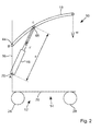
Figure 2 shows a diagrammatic side elevational view of the lifting device ofFigure 1 ; and -
Figure 3 represents the geometry of the lifting device used during the static analysis by which the weight of the imparted load can be determined. - Referring to the drawings, there is shown a
lifting device 10, in this case being apatient hoist 12, which comprises achassis 14, amast element 16 upstanding from thechassis 14, and alifting arm 18 supported by themast element 16. - The
chassis 14 includes twolegs 20 and across-member 22 connected between the twolegs 20 at or substantially atproximal ends 24 thereof. Thelegs 20 may be pivotable at or adjacent to thecross-member 22 so that they can be moved from a position in which they are parallel or substantially parallel to each other to a position in which they are splayed apart. When splayed, thelegs 20 diverge in a direction towards theirdistal ends 26. This enables, for example, a chair to be accommodated between the splayedlegs 20. - The pivoting of the
legs 20 may be motorised, for example by an electric motor being provided in thecross-member 22, or manual. - The
distal end 26 of eachleg 20 is provided with acastor 28, and two spaced apartoutriggers 30 extend oppositely to thelegs 20 from thecross-member 22. Eachoutrigger 30 includes afurther castor 32 at its distal end 34. - The
mast element 16 upstands from thecross-member 22. In this embodiment, themast element 16 includes twomast members 36 which are spaced apart at theirlower ends 38 and which are interconnected at theirupper ends 40. Thelower ends 38 of themast members 36 are supported by thecross-member 22 at or adjacent to side edges of thecross-member 22, thereby improving lateral stability. - The
mast members 36 are aligned so as to be in parallel with each other, but are non-planer. In this case, eachmast member 36 is at least in part arcuate, defining substantially a swan-neck profile. - In this case, the
mast element 16 is fixed. However, the mast element may be height-adjustable, and typically this would be via a telescopic adjustment mechanism. - A
proximal end 42 of thelifting arm 18 is pivotably connected to themast element 16 at afirst pivot 44 at the interconnectedupper ends 40 of themast members 36. Thelifting arm 18 is raised and lowered by telescopic extension and retraction of alifting arm actuator 46 which is pivotably connected to thelifting arm 18 at asecond pivot 48 partway between the proximal anddistal ends second pivot 48 is preferably closer to theproximal end 42 of thelifting arm 18 than thedistal end 50. - The
lifting arm 18 has, in this case, a non-planer longitudinal extent. The longitudinal extent is smoothly and continuously arcuate or curved from thedistal end 50 to theproximal end 42. However, it may include one or more rectilinear portions, as necessity dictates. - The free
distal end 50 of thelifting arm 18 is provided with aspreader bar attachment 52 in the form of a spindle pivotable about a rigid vertical or substantially vertical axis. - A
spreader bar 54 comprises asling hanger 56 and asling hanger support 58. Thesling hanger support 58 which is of generally inverted U-shaped configuration is attached to the spindle, and thesling hanger 56 which is of generally Y-shaped configuration is connected to the lower ends of the two arms of thesling hanger support 58 so as to be pivotable about a generally horizontal axis. Thesling hanger 56 has studs orconnectors 60 for releasable attachment of a patient support sling, which is typically a full body support sling. - In this embodiment, a
spreader bar actuator 62 is provided to provide powered control of thesling hanger 56. Thespreader bar actuator 62 is mounted on one side of thesling hanger support 58 and extends to a point on thesling hanger 56 which is adjacent to the pivot between thesling hanger support 58 and thesling hanger 56. Thespreader bar actuator 62 is preferably battery powered and controlled by an associated user-controller. - The
lifting arm actuator 46 includes anactuator housing 64 in or on which is receivable arechargeable battery pack 65, and which includes a user-operablelifting arm controller 66. Thelifting arm controller 66 is typically also a remotely operable device thereby allowing a carer the greatest degree of freedom and control. - A
lower end 68 of theactuator 46 is pivotably mounted at athird pivot 70 to a cross-bar 72 extending substantially horizontally between themast members 36 partway along their longitudinal extents. Typically, theactuator housing 64 extends around thethird pivot 70 and at least a majority of the cross-bar 72. - A
telescopic ram 74 of theactuator 46 extends from anupper end 76 of theactuator housing 64 to thesecond pivot 48. - The
first pivot 44 incorporates afirst torque sensor 78 for outputting a first torque signal indicative of a torque imparted between the liftingarm 18 and themast element 16 at thefirst pivot 44. Thefirst torque sensor 78 beneficially includes at least one strain gauge mounted on at least one flexure strip element which interconnects the liftingarm 18 and themast member 36. - Conveniently two flexure strip elements arranged at right angles are used.
- Although preferably at the
first pivot 44, it may be beneficial to include a supplementary first torque sensor along the liftingarm 18 to measure a torque or bending moment imparted during use. Thefirst torque sensor 78 may be dispensed with in favour of the supplementary first torque sensor. - The
third pivot 70 incorporates a second torque sensor 80 for outputting a second torque signal indicative of a torque imparted between the liftingarm actuator 46 and the cross-bar 72 of themast element 16 at thesecond pivot 48. The second torque sensor 80 again beneficially includes at least one strain gauge mounted on at least one flexure strip element which interconnects thelifting arm actuator 46 and the cross-bar 72. - Although preferably at the
third pivot 70, it may be beneficial to include a supplementary second torque sensor along thelifting arm actuator 46 to measure a torque or bending moment imparted during use. As before, the second torque sensor 80 may be dispensed with in favour of the supplementary second torque sensor. - Although preferably provided at the
third pivot 70 in this embodiment, the second torque sensor 80 or a further second torque sensor can be provided at thesecond pivot 48 in the manner as described above. - The
lifting arm actuator 46 also includes aload cell 82 for outputting a load signal corresponding to a load imparted to thelifting arm actuator 46, typically being via the liftingarm 18 once a patient is lifted. - The
load cell 82 may conveniently be of an S-shaped bending beam configuration, and is preferably on thelifting arm actuator 46 adjacent to thethird pivot 70. Beneficially, theload cell 82 may be coupled with the second torque sensor 80 arrangement in piggy-backed fashion, thereby providing a compact unit for measuring load and torque at or adjacent to a single point. - Alternatively the second torque sensor 80 and the
load cell 82 can be combined into a single integral multi-component transducer. - The or a said
load cell 82 may additionally or alternatively be utilised at or adjacent to thesecond pivot 48, or along thelifting arm actuator 46. - Conveniently, the
load cell 82 may be in the form of a shear pin load cell which could thus be accommodated within the second and/orthird pivots - The
lifting arm actuator 46 also includes adisplacement sensor 84, such as a shaft encoder, for outputting a displacement signal corresponding to a linear displacement of thelifting arm actuator 46. Preferably, this is incorporated within or on thetelescopic ram 74 of thelifting arm actuator 46, but may additionally or alternatively be within theactuator housing 64. - Although linear displacement is preferably monitored, the displacement could be angular, for example if the extension and retraction of the ram is screwed rotation.
- Output signals of the
first torque sensor 78, supplementary first torque sensor if provided, second torque sensor 80, supplementary second torque sensor if provided,load cell 82 anddisplacement sensor 84 are inputted to a calculation unit 86 having processing circuitry 88, preferably provided within theactuator housing 64. - It has been determined that there is a determinable relationship between a weight applied to the
sling hanger 56 at the end of the liftingarm 18, the extension of thelifting arm actuator 46, and the force acting in theram 74 of thelifting arm actuator 46 to support the liftingarm 18. - It has also been determined that detrimental influences resulting from friction at
pivots arm 18 and themast member 36, the liftingarm actuator 46 and the liftingarm 18, and thelifting arm actuator 46 and themast member 36, as well as within thelifting arm actuator 46 itself, for example, in bearings, impact the accuracy of the measured load. - Consequently, if these frictional forces, and in particular torques at the
pivots distal end 50 of the liftingarm 18 can be determined. - Referring now to
Figure 3 , the static analysis is described. The patient weight force W is balanced by the lifting arm actuator force F and the 'parasitic' torque MA at the second pivot A and MB at the first pivot B, which are distributed around the lifting device structure and thus spaced apart. If all three are measured, the variable lifting arm actuator length s is known, along with remaining geometry of the lifting device then the weight W at the distal end of the lifting arm can be calculated. - Moments are taken around the second pivot B as follows :

- Where h is horizontal distance from the first pivot A to the actuator. Therefore :

- With F, MA and MB measured by the respective load cell, second torque sensor and the first torque sensor, h and H can be calculated from the geometric quantities. This reduces to finding the angle α and the 3 angles β, γ and δ of the triangle ABC.
- In the triangle ABC, the length of all three sides a, b, s is known, since s being a variable is determined by the displacement sensor on the lifting actuator.
- From this :

- Therefore :

- Which follows that:

- β, γ can now be calculated :


- This provides all the quantities for the processing circuit of the calculation unit to utilise in equation 2) as follows :

- By way of example and based on the lifting device shown in
Figure 1 , the input values are substantially as follows: - a=700mm
- b=241 mm
- 1= 901mm
- s=605-905mm
- This leads to a load F of 6500N for a weight W of 2000N for the lifting arm actuator withdrawn, and nearly 10000N for the lifting arm actuator extended at the same weight W.
- The influence of the parasitic moments can be estimated easily by calculation: Assuming MA and MB are both 10Nm, the 2000N weight value is affected by 22N, or about 2%.
- For the same conditions, a lifting arm actuator length change of 1 mm produces a weight change of 3.3N.
- It can therefore be deduced that at least a 1000kg (10kN) load cell in the lifting arm actuator is required.
- The influence of the parasitic torques is small, and typically the torques are likely to be small also. Assuming that the 10 Nm is typical, a torque uncertainty of 1 Nm would be equivalent to a 0.1% error. It is possible to achieve this uncertainty or better with a 10 Nm sensor.
- Since there is a trade-off between capacity and accuracy, the magnitudes of the torques likely to be encountered in various different lifting devices must be recognised so that suitable transducers, being the load cell and torque sensors, can be utilised in the specific lifting device.
- It has been noted that the lifting arm actuator length sensitivity is high. As such, an accuracy of at least 0.1 mm from the actuator is required, however the displacement signal generated by conventionally known means will be able to achieve this.
- It is also recognised that elastic deformation of the structure of the lifting device should also be evaluated, and in all likelihood a degree of correction should be applied to the calculations by the processing circuit.
- Although the lifting device described above is a freestanding mobile patient or invalid hoist, any lifting device can incorporate the distributed-sensing scale as outlined. The invalid hoist enables weighing of a patient suspended from the lifting arm, but the distributed-sensing scale is applicable to fixed or wall / ceiling mounted hoists if torques and/or bending moments are imparted during use. The lifting device may be a hoist or crane within different fields, such as construction or automotive, as well as in the medical and patient care fields.
- The embodiments described above are provided by way of examples only, and various other modifications will be apparent to persons skilled in the field without departing from the scope of the invention as defined by the appended claims.
Claims (15)
- A lifting device (10) comprising a support element (14), a lifting arm (18) which is pivotably connected to the support element, an actuator (46) which is pivotably connected to the lifting arm (18) and the support element (14) for raising and lowering the lifting arm (18), a load cell (82) for outputting a load signal corresponding to a load imparted to the actuator (46), a first torque sensor (78) for outputting a first torque signal corresponding to a first torque imparted at at least one of the pivot (44) between the lifting arm (18) and the support element (14) and along the lifting arm (18), a second torque sensor (80) for outputting a second torque signal corresponding to a second torque imparted at at least one of the pivot (80) between the actuator (46) and the support element (14), the pivot (48) between the actuator (46) and the lifting arm (18) and along the actuator (46), a displacement sensor (84) for outputting a displacement signal corresponding to a displacement of the actuator (46), and calculation means (86) for calculating a weight at a distal end (50) of the lifting arm (18) based on the load signal, first and second torque signals, and the displacement signal.
- A lifting device (10) as claimed in claim 1, wherein the load cell (82) is on the actuator (46).
- A lifting device (10) as claimed in claim 2, wherein the load cell (82) is at or adjacent to the pivot between the actuator (46) and the support element (14).
- A lifting device (10) as claimed in claim 2, wherein the load cell (82) is at or adjacent to the pivot between the actuator (46) and the lifting arm (18).
- A lifting device (10) as claimed in any one of claims 1 to 4, wherein the load cell (82) and the second torque sensor (80) are provided together.
- A lifting device (10) as claimed in any one of claims 1 to 4, wherein the load cell (82) and the second torque sensor (80) are provided at or adjacent to opposite ends of the actuator (46).
- A lifting device (10) as claimed in any one of claims 1 to 6, wherein the load cell (82) is a load pin provided at at least one of the pivot (70) between the actuator (46) and the support element (14) and the pivot (48) between the actuator (46) and the lifting arm (18).
- A lifting device (10) as claimed in any one of claims 1 to 7, wherein the first torque sensor (78) is in the pivot between the lifting arm (18) and the support element (14).
- A lifting device (10) as claimed in any one of claims 1 to 7, wherein the first torque sensor (78) is on the lifting arm (18).
- A lifting device (10) as claimed in any one of claims 1 to 9, wherein the second torque sensor (80) is in the pivot between the actuator (46) and the support element (14).
- A lifting device (10) as claimed in any one of claims 1 to 9, wherein the second torque sensor (80) is in the pivot between the actuator (46) and the lifting arm (18).
- A lifting device (10) as claimed in any one of claims 1 to 9, wherein the second torque sensor (80) is on the actuator (46).
- A lifting device (10) as claimed in any one of claims 1 to 12, wherein the displacement sensor (84) is on the actuator (46).
- A lifting device (10) as claimed in any one of claims 1 to 13, wherein the displacement sensor (84) outputs a displacement signal corresponding to a linear displacement of the actuator (46).
- A lifting device (10) as claimed in any one of claims 1 to 14, wherein the actuator (46) is pivotably connected to the lifting arm (18) between its proximal and distal ends (42, 50).
Applications Claiming Priority (1)
| Application Number | Priority Date | Filing Date | Title |
|---|---|---|---|
| GB1019778.8A GB2485770A (en) | 2010-11-23 | 2010-11-23 | Lifting Device with Distributed-Sensing Scale |
Publications (2)
| Publication Number | Publication Date |
|---|---|
| EP2455050A2 true EP2455050A2 (en) | 2012-05-23 |
| EP2455050A3 EP2455050A3 (en) | 2012-11-07 |
Family
ID=43467111
Family Applications (1)
| Application Number | Title | Priority Date | Filing Date |
|---|---|---|---|
| EP11189047A Withdrawn EP2455050A3 (en) | 2010-11-23 | 2011-11-14 | Lifting device with distributed-sensing scale |
Country Status (5)
| Country | Link |
|---|---|
| US (1) | US20120128448A1 (en) |
| EP (1) | EP2455050A3 (en) |
| AU (1) | AU2011250861A1 (en) |
| CA (1) | CA2757785A1 (en) |
| GB (1) | GB2485770A (en) |
Cited By (1)
| Publication number | Priority date | Publication date | Assignee | Title |
|---|---|---|---|---|
| EP3453373B1 (en) * | 2017-09-12 | 2020-11-04 | Groupe Winncare | Connection unit for a lifting arrangement and such a lifting arrangement |
Families Citing this family (4)
| Publication number | Priority date | Publication date | Assignee | Title |
|---|---|---|---|---|
| FI127826B (en) * | 2014-08-01 | 2019-03-15 | Konecranes Oyj | Method of detecting a worn link in a chain, and a hoist arrangement |
| US9790696B2 (en) * | 2015-03-02 | 2017-10-17 | Odin, Llc | Deck with a slidable platform |
| US9617075B2 (en) | 2015-03-24 | 2017-04-11 | Joseph Porat | System and method for overhead warehousing |
| IL299825B2 (en) * | 2016-02-23 | 2024-07-01 | Deka Products Lp | Mobility device control system |
Family Cites Families (18)
| Publication number | Priority date | Publication date | Assignee | Title |
|---|---|---|---|---|
| GB1500501A (en) * | 1974-04-10 | 1978-02-08 | Pye Ltd | Crane load indicating arrangement |
| US4677579A (en) * | 1985-09-25 | 1987-06-30 | Becor Western Inc. | Suspended load measurement system |
| US5263597A (en) * | 1991-09-18 | 1993-11-23 | Stewart James T | Crane load instrument and method therefor |
| US5143232A (en) * | 1991-09-18 | 1992-09-01 | Stewart James T | Crane load instrument and method therefor |
| GB9902859D0 (en) * | 1999-02-10 | 1999-03-31 | Arjo Ltd | Invalid hoists |
| NL1013174C2 (en) * | 1999-09-29 | 2001-04-03 | Careflex Holding Bv | Lifting device. |
| US6610935B1 (en) * | 1999-11-17 | 2003-08-26 | Sieco, Inc. | Torque compensated weight sensing modules |
| US7690056B2 (en) * | 2004-03-26 | 2010-04-06 | Millennium Medical Products, Inc. | Stretcher supporter for a storable patient lift and transfer device and method for doing the same |
| US8104115B2 (en) * | 2005-05-09 | 2012-01-31 | Hecare Systems Aps | Handling system for lifting or moving a person, a weighting system and method of lifting and moving a person |
| JP5239776B2 (en) * | 2008-11-19 | 2013-07-17 | トヨタ自動車株式会社 | Transfer support device and control method of transfer support device |
| US8474794B2 (en) * | 2009-03-06 | 2013-07-02 | Liko Research & Development Ab | Lift control systems for lifting devices and lifting devices comprising the same |
| CN102575457B (en) * | 2009-10-19 | 2014-12-17 | 日立建机株式会社 | Operation machine |
| US8779306B2 (en) * | 2010-02-19 | 2014-07-15 | Methode Electronics, Inc. | Weight sensing method and apparatus for forklifts |
| CA2743647C (en) * | 2010-06-17 | 2018-06-19 | Key Energy Services, Llc | Method and system for automatically setting, adjusting, and monitoring load-based limits on a well service rig |
| JP5645069B2 (en) * | 2010-10-21 | 2014-12-24 | 株式会社ジェイテクト | Vehicle steering system |
| WO2012139575A1 (en) * | 2011-04-15 | 2012-10-18 | INS - Europe | A method for estimating volume |
| US10045895B2 (en) * | 2011-08-24 | 2018-08-14 | Liko Research & Development Ab | Patient stand assist and therapy devices and methods |
| US20140020175A1 (en) * | 2012-07-12 | 2014-01-23 | Steven A. Dixon | Monitoring systems devices and methods for patient lifts |
-
2010
- 2010-11-23 GB GB1019778.8A patent/GB2485770A/en not_active Withdrawn
-
2011
- 2011-11-14 EP EP11189047A patent/EP2455050A3/en not_active Withdrawn
- 2011-11-14 CA CA2757785A patent/CA2757785A1/en not_active Abandoned
- 2011-11-18 AU AU2011250861A patent/AU2011250861A1/en not_active Abandoned
- 2011-11-21 US US13/300,682 patent/US20120128448A1/en not_active Abandoned
Non-Patent Citations (1)
| Title |
|---|
| None |
Cited By (1)
| Publication number | Priority date | Publication date | Assignee | Title |
|---|---|---|---|---|
| EP3453373B1 (en) * | 2017-09-12 | 2020-11-04 | Groupe Winncare | Connection unit for a lifting arrangement and such a lifting arrangement |
Also Published As
| Publication number | Publication date |
|---|---|
| CA2757785A1 (en) | 2012-05-23 |
| GB201019778D0 (en) | 2011-01-05 |
| EP2455050A3 (en) | 2012-11-07 |
| AU2011250861A1 (en) | 2013-06-13 |
| US20120128448A1 (en) | 2012-05-24 |
| GB2485770A (en) | 2012-05-30 |
Similar Documents
| Publication | Publication Date | Title |
|---|---|---|
| US9987182B2 (en) | Hospital bed with patient weight and displacement sensors for determining at least one of lateral and longitudinal patient location on a patient support assembly | |
| EP2455050A2 (en) | Lifting device with distributed-sensing scale | |
| ES2302289T3 (en) | MOBILE WORK TEAM WITH EXTENSIBLE SUPPORT ARMS. | |
| CN108348296B (en) | Robotic surgical system and method of monitoring applied force | |
| JP5688873B2 (en) | Operating table | |
| JP5964944B2 (en) | Electric actuator system | |
| JP6970706B2 (en) | Walking support equipment | |
| US20060278771A1 (en) | Load carrying apparatus with security detection system | |
| US6329612B1 (en) | Invalid hoists | |
| WO2011129692A1 (en) | Hand lift truck | |
| ES2313111T3 (en) | WEIGHING CELL. | |
| CA2391207C (en) | Invalid hoist | |
| JP2009270902A (en) | Stretcher type weighing machine | |
| US20230338213A1 (en) | Lift Systems And Load Cells For Patient Support Apparatus | |
| ES2316905T3 (en) | BED FOR CARE. | |
| CN208333647U (en) | A kind of medical scale and medical scale component | |
| CN210664735U (en) | Medical electronic scale | |
| GB2475080A (en) | Weighing suspended loads having a pivotable load pin attached to a load cell | |
| SK9723Y1 (en) | Weighing apparatus on a patient support with scissor lifting | |
| PL230040B1 (en) | Mobile medical transporting device, preferably for transportation within hospital | |
| Lou et al. | An instrumented rod rotator |
Legal Events
| Date | Code | Title | Description |
|---|---|---|---|
| PUAI | Public reference made under article 153(3) epc to a published international application that has entered the european phase |
Free format text: ORIGINAL CODE: 0009012 |
|
| AK | Designated contracting states |
Kind code of ref document: A2 Designated state(s): AL AT BE BG CH CY CZ DE DK EE ES FI FR GB GR HR HU IE IS IT LI LT LU LV MC MK MT NL NO PL PT RO RS SE SI SK SM TR |
|
| AX | Request for extension of the european patent |
Extension state: BA ME |
|
| PUAL | Search report despatched |
Free format text: ORIGINAL CODE: 0009013 |
|
| AK | Designated contracting states |
Kind code of ref document: A3 Designated state(s): AL AT BE BG CH CY CZ DE DK EE ES FI FR GB GR HR HU IE IS IT LI LT LU LV MC MK MT NL NO PL PT RO RS SE SI SK SM TR |
|
| AX | Request for extension of the european patent |
Extension state: BA ME |
|
| RIC1 | Information provided on ipc code assigned before grant |
Ipc: A61G 7/10 20060101AFI20121004BHEP |
|
| STAA | Information on the status of an ep patent application or granted ep patent |
Free format text: STATUS: THE APPLICATION IS DEEMED TO BE WITHDRAWN |
|
| 18D | Application deemed to be withdrawn |
Effective date: 20130508 |