EP2454933B1 - Procédé et appareil pour reprendre des boutures de plantes - Google Patents
Procédé et appareil pour reprendre des boutures de plantes Download PDFInfo
- Publication number
- EP2454933B1 EP2454933B1 EP10191996.7A EP10191996A EP2454933B1 EP 2454933 B1 EP2454933 B1 EP 2454933B1 EP 10191996 A EP10191996 A EP 10191996A EP 2454933 B1 EP2454933 B1 EP 2454933B1
- Authority
- EP
- European Patent Office
- Prior art keywords
- plant
- cutting
- carrier
- plants
- image
- Prior art date
- Legal status (The legal status is an assumption and is not a legal conclusion. Google has not performed a legal analysis and makes no representation as to the accuracy of the status listed.)
- Not-in-force
Links
Images


Classifications
-
- A—HUMAN NECESSITIES
- A01—AGRICULTURE; FORESTRY; ANIMAL HUSBANDRY; HUNTING; TRAPPING; FISHING
- A01G—HORTICULTURE; CULTIVATION OF VEGETABLES, FLOWERS, RICE, FRUIT, VINES, HOPS OR SEAWEED; FORESTRY; WATERING
- A01G2/00—Vegetative propagation
- A01G2/30—Grafting
Definitions
- the present invention relates to a method for strike cutting of plants.
- Such a method comprising the subsequent steps of positioning a plant to a carrier, taking an image of at least a part of the plant by an image taking device, analysing the image as to determine a cutting position, cutting the plant into at least one separated part and a remaining part with a cutting device, transferring the at least one separated part of the plant to an output device.
- the method further comprising deciding whether the plant has to be cut further after said cutting, and comprising a final step of removing the remaining part of the plant from the carrier if no further cutting is required.
- the present invention also relates to an apparatus for strike cutting of plants. More in particular it relates to such an apparatus comprising a carrier for carrying at least two plants, an image taking device for providing an image of at least a part of a plant positioned at the carrier, a processing unit for analysis of the image, a cutting device for cutting a part of a plant into a separated part and a remaining part and configured for receiving a signal from the processing unit, a separation device for transferring a separated part of the plant to an output device, the separation unit comprising a gripper for gripping the part of the plant that has to be separated wherein the carrier and the cutting device are movable with respect to each other.
- Strike cutting of plants is a process in horticulture that is mainly performed by man power. It is a labour intensive process and therefore costly. On the other hand it is a difficult process to be automated because the cutting of the plants has to be performed carefully and at specific positions of a plant.
- Apparatus and method for mechanical separation of cuttings for plants are known, for example from European patent application EP 0 853 873 A1 .
- This known method comprises the manual input of the plants into carriers that are fixed to a conveyor belt. More in particular, in this known method the plants hang in a carrier and this method therefore is in particular suited for plants which are free, viz. are separated from the pot in which the plants are grown.
- the known apparatus comprises several cutting and vision units in series. A first station of the apparatus is for cutting a lower part of the plant. In subsequent stations other parts of the plant are cut. This known apparatus therefore comprises as many cutting and vision units as the number of cuttings from one plant. The throughput of the plants is, due to sequential character of the process, determined by the most time consuming part of the process.
- An objective of the present invention is to provide a method for strike cutting a plant which method is fast and accurate.
- This objective of the invention is obtained by the method according to the invention which is characterised in that if further cutting of the plant is required, this further cutting is performed after at least one other plant has been cut with said cutting device.
- An advantage of cutting at least one other plant before further cutting the first plant further, is that the first plant can be reoriented while the cutting device remains in operation.
- the above mentioned objective is obtained with this advantage because the cutting process of plants will not be hindered by reorientation of the plant in case of additional cutting. More in particular the flow of plants to the cutting device can be continuous or semi-continuous. Further, different steps of the process can be performed in parallel for different plants.
- the method according to the invention allows a plant being cut whereas at the same time another plant is visually analysed and/or oriented. As a consequence, the process will be fast.
- the cutting process will be accurate because there is sufficient time to orient the plant carefully before the additional cutting takes place.
- the positioning of the plant at the carrier comprises placing the plant in a plant holder, the plant holder being attached to the carrier.
- the method comprises the step of moving the plant and the image taking device with respect to each other to obtain different views of the plant.
- An advantage of this embodiment is that a more detailed view, for example a three dimensional view of the plant can be obtained. Further the moving of the plant and image taking device with respect to each other reduces the hindrance caused by parts of the plant that are blocking views in certain positions.
- the moving of the plant and the image taking device with respect to each other comprises rotating of the plant along an axis parallel to the stem of the plant.
- Another objective of the present invention is an apparatus for strike cutting of a plant which apparatus combines a compact construction and accurate cutting with a high speed of the strike cutting.
- the apparatus of the invention being characterised in that the carrier is constructed as to present the remaining part to the cutting device for an additional cutting after at least one other plant has been presented to the cutting device.
- An advantage of a construction that allows the cutting of at least one other plant before the plant is cut further, is that during cutting of said other plant, the first plant can be reoriented on the carrier as to provide a proper orientation for the further cutting.
- the carrier comprises a mechanical stiff bearing.
- a stiff mechanical bearing is that the position of the plants and their trajectory is well defined. As a consequence the image taking device can operate independently from the cutting device. When at a specific moment in time a first plant is being cut by the cutting device, the exact orientation of a second plant with respect to the bearing can be determined in the image taking device. Subsequently, the second plant will be moved towards the cutting device, its orientation at the cutting device being well established because the trajectory is fully determined by the moving of the stiff bearing to which the plant is positioned.
- the mechanical stiff bearing is a plate being rotatable around an axis perpendicular to is surface.
- the plants are provided and transported in a standing position.
- Such embodiments of the invention may be used for cutting all types of plants.
- fittonia, hedera, buxus and roses are plants that preferably are cut when standing.
- the method is not limited to standing plants. If proper mechanical constructions are used for implementing the method, it can also be used for plants that are transported hanging. It has also to be understood that the method and apparatus are not limited to a specific type of cutting, it may be used, among others, to slip and to trim plants.
- One of the first steps that have to be performed is providing the plants that have to be cut.
- Providing the plants can be performed manually, but it is preferred to use an automated supply system.
- the plants may be provided in a continuous or semi-continuous flow of plant holders, for example pots, each containing a single plant.
- a conveyor belt may be a favourable way of providing the pots, but any other supply system will satisfy.
- the plants are transported from the supply system to the carrier in order to position the plant at the carrier.
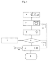
- Positioning (1) of the plant to the carrier can be performed in several ways and includes methods like placing the plant on the carrier, clamping the plant, or any other method that allows the plant to be transported by the carrier.
- pots with plants can be simply pushed onto the carrier.
- the plants are picked up with a gripper and placed on or in plant holders that are fixed to or placed on the carrier.
- the positions where the plants are place are preferably predefined locations, viz. locations that have a fixed position on the carrier.
- Predefining the locations includes methods in which the position to the carrier is determined after the plant has been positioned. However, it is preferred to have the locations defined before a plant is positioned. This includes methods like marking areas where the plants have to be placed, and using clamping means located at well defined positions of the carrier.
- the method comprises a step (2) in which an image is taken from the plant. Taking the image can for instance be done by a photo or video camera making one or more pictures of the plant.
- the image taking device must be a device, for instance a digital camera, that allows further processing of the image automatically by appropriate software.
- the image or a plurality of images is used for analysis of the plant geometry in a subsequent step (3).
- the image of the plant can be obtained by using visible light, however it might also be obtained by infrared light or any other suitable wavelength of electromagnetic radiation, for example radar.
- the image need even not to be obtained by electromagnetic radiation, but may also be obtained by, for example, ultrasonic or other acoustic waves.
- Making images may also mean real-time analysis of the image as obtained by a camera.
- a camera is a digital camera making many pictures at a high speed to allow fast automatic analysis.
- Image analysis is required to analyse the image and to determine the cutting position or positions. This image need not to be a image of the whole plant, but the image must cover at least one cutting position of the plant. Typically, the cutting positions are determined by locating the stem and the interconnection with the leave stems. Those skilled in the art of image analysis will know how to implement an algorithm to determine a cutting position. It is appreciated that the cutting position, in general, will depend on the type of plant. The image analysis can also be used to determine the position of the plant at the carrier if required, for instance when the position of the plant is not defined before the plant is positioned at the carrier.
- step (6) Based on the image analysis it is determined in step (6) whether or not the plant has to be cut or has to be cut further as will be discussed below. If no cutting or further cutting is required or no proper cutting position could be found, the plant will be removed (7) from the carrier.
- the plant has to be provided to a cutting device or a cutting device has to be provided to the plant.
- the cutting device will cut the plant into a separated part and a remaining part in a subsequent step (4) at a proper cutting position.
- the separated part of the plant is that part of the plant that is no longer positioned at the carrier due to the cutting.
- the separated part is hold by a gripper as of a moment just before the cutting.
- This gripper may transfer (5) the separated part to an output device.
- the use of a gripper is preferred because a gripper allows the separated part to be transferred in a well defined orientation into, for example, a pot.
- the separated part can also be transferred to an output device in a different way.
- the separated part may, for example, fall off and collected by hand or any suitable transferring device.
- Such a transferring device may be a conveyor belt that transports the separated part of he plant.
- the number of cuttings can be determined on forehand based on the type of plant, by visual observation of a person, or automatically by means of image analysis. For a fast and accurate strike cutting an image analysis of the individual plants is preferred.
- the total number of cuttings may be determined before a first cutting of the plant in step (2), or it may be determined later, for instance after cutting. In the later situation, indicated by II in figure 1 , it has to be decided after each cutting whether the plant has to be cut further to obtain the required total number of cuttings. In the first situation, indicated by I in figure 1 , the decision about further cutting may be based on the earlier obtained image analysis or on a further image analysis of the remaining part of the plant.
- the plant will be removed from the cutting device or, as the case may be, the cutting device will be removed from the plant.
- This removal makes the cutting device available for cutting another plant (8) that has been positioned at the carrier after the plant for which the process is described here.
- the plant and the cutting device will be presented to each other later. More in particular, the remaining part of the plant may be inserted in the continuous of semi-continuous flow of plants. This process step can be performed as may times as the number of cuttings.
- the carrier will be carrying plants in different stages of cutting, viz. plants that have to be cut for the first time and plants that have been cut already once or even more times. If all plants have to be cut only once, all locations of the carrier will be available for input of plants to-be-cut after removal of the remaining part of the plant from the carrier. In all other situations, not all locations are available for new plants from the supply system.
- the method in a fully automated manner, one will have to adjust the different speeds and flows. For an optimal performance, one will have to tune the flow of the supply system and the transfer speed to the output device. The actual throughput of plants may, among others, depend on the speed of image analysis and the cutting process.
- the remaining part will preferably also be used as a cutting and be transported to the output device. However, this part may also be treated as waste.
- One image representing just one view of the plant often will not satisfy for determining a proper cutting position.
- the structure of most plants is too complex to allow finding the proper cutting position from one view only. Therefore it may be preferred to obtain images of the plant from different view points by moving the plant and the image taking device with respect to each other.
- the plant has to be cut at the stem. Rotating the plant in front of a camera around its stem or, more general along an axis that is parallel to its stem, may provide additional information to obtain a more complete picture of the plant. More in particular, a kind of three dimension view of the plant may be constructed to determine the proper cutting position or positions.
- the plant may be re-oriented to provide the most optimal orientation of the plant with respect to the cutting device. What actually the most optimal orientation is, will depend, among others, on the complexity of the plant, the degrees of freedom of the cutting device, the speed of the various steps of the method.
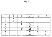
- Figure 2 illustrates a possible time cycle of the method for three plants.
- plant A is positioned at the carrier.
- an image is taken of the plant A, while a second plant B is positioned at the carrier.
- Some time later at time t3 plant A is being cut, while an image is taken of plant B.
- a separated part A1 of plant A1 is transferred to the output device, plant B is being cut, and a third plant C is positioned at the carrier.
- a time t5 an image is taken of this third plant C, the remaining part A2 of plant A is cut and a separated part B 1 of plant B is transported to the output device.
- plant C is presented to the cutting device, a second separated part A3 of plant A is transferred to the cutting device, while the remaining part A4 of plant A, that need not to be cut further is removed from the carrier.
- the remaining part B2 of plant B is being cut, the separated part C1 of plant C is transferred to the output device and the remaining part B1 of plant B that need not to be cut further is removed from the carrier.
- FIG. 3 A preferable embodiment of the apparatus according to the invention will be discussed here in more detail referring to figure 3 .
- This embodiment that is suited for the strike cutting of standing plants, comprises an input device (12) for providing a continuous or semi-continuous flow of individual plants that have to be cut and an output device (20) for transporting the strike cuttings.
- an input device for providing a continuous or semi-continuous flow of individual plants that have to be cut
- an output device for transporting the strike cuttings.
- an input device is preferred, one will appreciate that such an input device is not essential because the plants can also be provided to the carrier manually.
- a carrier (11) is situated between the input and the output device.
- a function of the carrier is to carry and transport the plants during the process, including plants that are cut already once or more times.
- the carrier according the embodiment discussed here, comprises a rotatable flat plate (19) suited for carrying and transporting standing plants, more in particular for transporting the plants from the camera (14) to the separation device.
- the surface of the plate will be completely flat in order to carry pots, or comprise some rims to define pot positions more accurately.
- a more dedicated carrier may comprise special plant holders.
- the preferred number of locations for plants on the carrier depends on several parameters, including the fluctuation in the number of cuttings for a single plant. If the variation is large, one may prefer a large number of spots to absorb the fluctuations. The same holds if the fluctuations in the supply of new plants is large. It may be preferred to keep the number of locations on the carrier as small as possible in order to obtain a compact apparatus. In addition, a large number of locations and, consequently, a large carrier will result in higher costs.
- the carrier may have between 2 and 20 locations (18) for positioning plants, more preferably between 3 and 10 locations, and even more preferably 4, 5 or 6 locations, depending among others on the size of the carrier and the plants and, as will discussed later, the variation in the number of cuttings for the plants. In particular a carrier with 4, 5 or 6 locations for positioning plants is observed to be very practical.
- This embodiment of the apparatus further comprises a camera (14) for taking an image of the plants and a separation device (16) for separating a part from the plant.
- the separation device comprises a gripper (17) for gripping the part that has to be separated and a cutting device (13) for cutting the stem of the plant.
- the gripper transposes the strike cutting to the output device (22), which output device preferably is suited for carrying pots or plant holders into which the cutting can be placed.
- the input device may be a conveyer belt that is suitable for carrying the pots with plants that have to be cut.
- the plants can be provided to the carrier for instance by shoving the pots onto the carrier. However, it is preferred to take the plants out of the pots and transfer the plants into plant holders that are fixed to the carrier.
- This process of taking a plant out of a pot and transfer it to a plant holder can be performed by robotic grippers well known to those skilled in the art. This gripper may be controlled electrically or pneumatically.
- An advantage of using plant holders is that they have uniform properties, allowing more accurate handling of the plants and that the position of the plants is rather well defined in this way.
- the predefined position of the plant on the carrier allows faster image analysis. Further, if the position of the plant on the carrier is known accurately, the trajectory of the plant during moving from the image taking device to the separation device will be more accurate, resulting in a better defined cutting position.
- a camera (14) or other image taking device is situated for making an image of the plant after it has been positioned at the carrier (11).
- the camera comprises or is connected with, a data processing unit (15) for the image analysis.
- the plant is rotated in front of the camera for providing a three-dimensional image of the plant.
- the plant holders of the carrier are constructed as to allow a controlled rotation about the vertical axis (31).
- the data processing unit comprises an algorithm for determining the best cutting position and orientation of the plant based on for example the distance between different branches of the plant, the accessibility for the cutting device of a cutting position without damaging the plant, the desired size of he strike cutting and the amount of chlorophyll.
- the separation device comprises a cutting device (13) which may for example be a knife or scissors. Those skilled in the art will find the most proper cutting tool for the type of plant.
- the separation device also comprises a gripper (17) to hold the separated part of the plant and to transfer it to the output device. For the standing plants, the gripper has to hold the plant above the cutting position.
- the cutting device and the gripper are integrated into a single robot arm in order to allow a good co-ordination between the cutting and gripping process and to obtain a compact construction, they need not be integrated.
- the camera and the separation device are placed at distinct positions along the rotatable carrier.
- the effect of this distance is that it will take a certain amount of time for the plant to arrive at the separation device after the image of the plant has been taken. This time can be used for calculating the proper cutting position and for rotating the plant in a position that is most favourable for easy access by the cutting device.
- the plant holders on the carrier are rotatable around an axis that is perpendicular to the surface of the carrier.
- images form different viewing points. Such images can be obtained by displacing the plant and the image taking device with respect to each other. It has been found that, in case the stem has to be cut, it is in particular favourable to rotate the plant around an axis parallel to the stem in front of the image taking device.
- the carrier may comprise rotatable plant holders (18).
- the apparatus as described above is in particular suited for standing plants.
- the apparatus according to the invention is also suited for plants that are hanging.
- Figure 4 shows an example how the embodiment of figure 3 can be modified accordingly.
- the carrier (11) comprises a conveyor belt (19) at which clamping means (18) for the plants are attached.
- a plate like the one in figure 4 or a similar transporting mechanism may be used.
- the relative position of the cutting device (13) and the gripper (17) of the separation device is different from the separation device shown in figure 4 for standing plants because the plants are attached to the carrier at their upper end instead of being positioned standing on the carrier.
Landscapes
- Life Sciences & Earth Sciences (AREA)
- Botany (AREA)
- Developmental Biology & Embryology (AREA)
- Environmental Sciences (AREA)
- Apparatuses For Bulk Treatment Of Fruits And Vegetables And Apparatuses For Preparing Feeds (AREA)
Claims (12)
- Méthode de bouturage de plantes, comprenant les étapes suivantes de :- positionnement (1) d'une plante sur un transport- prise d'une image (2) d'au moins une partie de la plante par un dispositif de prise de vue,- analyse (3) de l'image de manière à déterminer une position de coupe,- coupe (4) de la plante en au moins une partie séparée et une partie restante avec un dispositif de coupe,- transfert (5) d'au moins une partie séparée de la plante vers un dispositif de sortie,comprenant en outre la décision (6) de si la plante doit être davantage coupée après ladite coupe (4) et comprenant une étape finale (7) de retrait de la partie restante de la plante du transport si aucune coupe supplémentaire n'est requise.
caractérisée en ce que
si une coupe supplémentaire de la plante est requise, cette coupe supplémentaire est réalisée après qu'au moins une autre plante ait été coupée (8) avec ledit dispositif de coupe. - Méthode selon la revendication 1 dans laquelle l'étape de décision de si la plante doit être davantage coupée est réalisée automatiquement à l'aide de l'image.
- Méthode selon la revendication 1 ou 2, dans laquelle le positionnement de la plante sur le transport comprend le placement de la plante dans un support de plante, le support de plante étant fixé au transport.
- Méthode selon l'une quelconque des revendications précédentes, dans laquelle la plante est positionnée sur le transport dans une position droite
- Méthode selon l'une quelconque des revendications précédentes, comprenant une étape de déplacement de la plante et du dispositif de prise de vue l'un par rapport à l'autre pour obtenir différentes vues de la plante.
- Méthode selon la revendication 5, dans laquelle le déplacement comprend la rotation de la plante le long d'un axe parallèle à la tige de la plante.
- Méthode selon l'une quelconque des revendications précédentes, dans laquelle l'étape de transfert d'au moins une partie séparée de la plante vers un dispositif de sortie comprend le placement de la partie séparée de la plante dans un pot.
- Appareil (10) pour bouturer une plante selon la méthode de l'une quelconque des revendications précédentes, comprenant- un transport (11) pour transporter au moins deux plantes,- un dispositif de prise de vue (14) pour fournir une image d'au moins une partie d'une plante positionnée sur le transport,- une unité de traitement (15) pour analyse de l'image,- un dispositif de coupe (13) pour couper une partie d'une plante en une partie séparée (101) et une partie restante (102) et configuré pour recevoir un signal de l'unité de traitement,- un dispositif de séparation (16) pour transférer une partie séparée de la plante vers un dispositif de sortie, l'unité de séparation comprenant une pince (17) pour agripper la partie de la plante qui doit être séparéedans lequel le transport et le dispositif de coupe sont mobiles l'un par rapport à l'autre,
caractérisé en ce que le transport est construit de manière à présenter la partie restante (102) au dispositif de coupe pour une coupe supplémentaire après qu'au moins une autre plante (103) ait été présentée au dispositif de coupe. - Appareil selon la revendication 8, dans lequel le transport comprend un palier mécanique rigide (19).
- Appareil selon la revendication 8 ou 9, dans lequel le palier mécanique rigide est une plaque pouvant pivoter autour d'un axe (21) perpendiculaire à sa surface.
- Appareil selon l'une quelconque des revendications 8 à 10, dans lequel le transport comprend des supports de plantes (18) mobiles par rapport au palier, de préférence pouvant pivoter le long d'un axe (31) perpendiculaire au palier.
- Appareil selon la revendication 11 dans lequel le nombre de supports de plantes est 4, 5, ou 6
Priority Applications (2)
| Application Number | Priority Date | Filing Date | Title |
|---|---|---|---|
| EP10191996.7A EP2454933B1 (fr) | 2010-11-22 | 2010-11-22 | Procédé et appareil pour reprendre des boutures de plantes |
| DK10191996.7T DK2454933T3 (da) | 2010-11-22 | 2010-11-22 | Fremgangsmåde og apparatur til skæring af plantestiklinger |
Applications Claiming Priority (1)
| Application Number | Priority Date | Filing Date | Title |
|---|---|---|---|
| EP10191996.7A EP2454933B1 (fr) | 2010-11-22 | 2010-11-22 | Procédé et appareil pour reprendre des boutures de plantes |
Publications (2)
| Publication Number | Publication Date |
|---|---|
| EP2454933A1 EP2454933A1 (fr) | 2012-05-23 |
| EP2454933B1 true EP2454933B1 (fr) | 2013-06-05 |
Family
ID=43619755
Family Applications (1)
| Application Number | Title | Priority Date | Filing Date |
|---|---|---|---|
| EP10191996.7A Not-in-force EP2454933B1 (fr) | 2010-11-22 | 2010-11-22 | Procédé et appareil pour reprendre des boutures de plantes |
Country Status (2)
| Country | Link |
|---|---|
| EP (1) | EP2454933B1 (fr) |
| DK (1) | DK2454933T3 (fr) |
Families Citing this family (6)
| Publication number | Priority date | Publication date | Assignee | Title |
|---|---|---|---|---|
| EP2719273B1 (fr) | 2012-10-12 | 2018-02-28 | Nederlandse Organisatie voor toegepast- natuurwetenschappelijk onderzoek TNO | Procédé et appareil permettant de découper des végétaux |
| CN103314768B (zh) * | 2013-07-16 | 2015-12-23 | 舒海球 | 一种利用黄杨砧木的茶花嫁接方法 |
| CN103496586B (zh) * | 2013-09-18 | 2016-08-03 | 浙江理工大学 | 一种嫁接苗排序机构 |
| CN103621323B (zh) * | 2013-12-09 | 2015-01-21 | 浙江理工大学 | 自动换盘式嫁接机的旋转持苗器 |
| DE102016010618A1 (de) * | 2016-08-03 | 2018-02-08 | Bock Bio Science Gmbh | Vorrichtung und Verfahren zum Vermehren von Pflanzen |
| DE102019004848A1 (de) * | 2019-07-12 | 2021-01-14 | RoBoTec PTC GmbH | Vorrichtung und Verfahren zum Vermehren von Pflanzen |
Family Cites Families (5)
| Publication number | Priority date | Publication date | Assignee | Title |
|---|---|---|---|---|
| US5370713A (en) * | 1990-09-07 | 1994-12-06 | The Commonwealth Industrial Gases Limited | Automatic plant dividing system |
| NL1004687C2 (nl) | 1996-12-04 | 1998-06-05 | Boomkwekerij Bert Rombouts B V | Samenstel voor het mechanisch afscheiden van stekken van een (rozen)plantentak. |
| NL1017794C2 (nl) | 2001-04-09 | 2002-10-10 | Rombomatic B V | Inrichting voor het machinaal afscheiden van stekken van een plantentak. |
| NL1021463C2 (nl) * | 2002-09-16 | 2004-03-18 | Tno | Werkwijze voor het scheiden van rozetplanten. |
| NL1024536C2 (nl) * | 2003-10-14 | 2005-04-15 | Rombomatic B V | Inrichting voor het afscheiden van parten van een plantentak. |
-
2010
- 2010-11-22 DK DK10191996.7T patent/DK2454933T3/da active
- 2010-11-22 EP EP10191996.7A patent/EP2454933B1/fr not_active Not-in-force
Also Published As
| Publication number | Publication date |
|---|---|
| EP2454933A1 (fr) | 2012-05-23 |
| DK2454933T3 (da) | 2013-09-08 |
Similar Documents
| Publication | Publication Date | Title |
|---|---|---|
| EP2454933B1 (fr) | Procédé et appareil pour reprendre des boutures de plantes | |
| US7735626B2 (en) | Apparatus, method and system for handling, positioning, and/or automatically orienting objects | |
| US7697133B2 (en) | Methods and apparatus for analysis of phenotypic parameters and traits in plants | |
| CA2669191C (fr) | Appareil, procede et systeme de manipulation, de positionnement et/ou d'orientation automatique d'objets | |
| EP3199479B1 (fr) | Procédé de transfert d'articles | |
| US20230371445A1 (en) | Apparatus and method for planting plant cuttings | |
| CN109788737B (zh) | 用于繁殖植物的设备和方法 | |
| EP2922423B1 (fr) | Système et procédé d'échantillonnage de tissu de plante automatique | |
| CN114364255A (zh) | 用于繁殖植物的装置和方法 | |
| US7614182B2 (en) | Method for separating rosette plants | |
| EP3172954B1 (fr) | Système de scarification automatique et d'évaluation de la vitalité de semences et scarification automatique et procédé d'évaluation de la vitalité de semences | |
| TWI728544B (zh) | 袋式栽培菇類自動化採收系統及其方法 | |
| EP1829446A2 (fr) | Installation pour placer des boutures dans des blocs de plantation | |
| EP2719273B1 (fr) | Procédé et appareil permettant de découper des végétaux | |
| US5063791A (en) | Sampling of material | |
| EP3788867A1 (fr) | Système d'arrangement automatique de bouquets de fleurs | |
| WO2006087900A1 (fr) | Poste de réglage de semis | |
| NL1018768C2 (nl) | Werkwijze voor het verwijderen van het hart uit een kool, en inrichting daarvoor. | |
| CN109622422A (zh) | 水稻种子分拣装置及水稻种子切片采样设备 | |
| US20060037242A1 (en) | Device and method for fitting a sleeve around a pot plant | |
| JPH03236716A (ja) | 茸切断装置 | |
| JP2006180862A (ja) | 苗の調整ステーション | |
| JP2006180862A6 (ja) | 苗の調整ステーション | |
| Hojo et al. | Development of the crone seedlings handling system using 3D-sensor and force control gripper |
Legal Events
| Date | Code | Title | Description |
|---|---|---|---|
| PUAI | Public reference made under article 153(3) epc to a published international application that has entered the european phase |
Free format text: ORIGINAL CODE: 0009012 |
|
| AK | Designated contracting states |
Kind code of ref document: A1 Designated state(s): AL AT BE BG CH CY CZ DE DK EE ES FI FR GB GR HR HU IE IS IT LI LT LU LV MC MK MT NL NO PL PT RO RS SE SI SK SM TR |
|
| AX | Request for extension of the european patent |
Extension state: BA ME |
|
| 17P | Request for examination filed |
Effective date: 20121105 |
|
| GRAP | Despatch of communication of intention to grant a patent |
Free format text: ORIGINAL CODE: EPIDOSNIGR1 |
|
| RIC1 | Information provided on ipc code assigned before grant |
Ipc: A01G 1/06 20060101AFI20121123BHEP |
|
| GRAS | Grant fee paid |
Free format text: ORIGINAL CODE: EPIDOSNIGR3 |
|
| GRAA | (expected) grant |
Free format text: ORIGINAL CODE: 0009210 |
|
| AK | Designated contracting states |
Kind code of ref document: B1 Designated state(s): AL AT BE BG CH CY CZ DE DK EE ES FI FR GB GR HR HU IE IS IT LI LT LU LV MC MK MT NL NO PL PT RO RS SE SI SK SM TR |
|
| REG | Reference to a national code |
Ref country code: GB Ref legal event code: FG4D |
|
| REG | Reference to a national code |
Ref country code: CH Ref legal event code: EP |
|
| REG | Reference to a national code |
Ref country code: AT Ref legal event code: REF Ref document number: 615087 Country of ref document: AT Kind code of ref document: T Effective date: 20130615 |
|
| REG | Reference to a national code |
Ref country code: IE Ref legal event code: FG4D |
|
| REG | Reference to a national code |
Ref country code: DE Ref legal event code: R096 Ref document number: 602010007533 Country of ref document: DE Effective date: 20130801 |
|
| REG | Reference to a national code |
Ref country code: DK Ref legal event code: T3 |
|
| REG | Reference to a national code |
Ref country code: NL Ref legal event code: T3 |
|
| REG | Reference to a national code |
Ref country code: AT Ref legal event code: MK05 Ref document number: 615087 Country of ref document: AT Kind code of ref document: T Effective date: 20130605 |
|
| PG25 | Lapsed in a contracting state [announced via postgrant information from national office to epo] |
Ref country code: FI Free format text: LAPSE BECAUSE OF FAILURE TO SUBMIT A TRANSLATION OF THE DESCRIPTION OR TO PAY THE FEE WITHIN THE PRESCRIBED TIME-LIMIT Effective date: 20130605 Ref country code: SE Free format text: LAPSE BECAUSE OF FAILURE TO SUBMIT A TRANSLATION OF THE DESCRIPTION OR TO PAY THE FEE WITHIN THE PRESCRIBED TIME-LIMIT Effective date: 20130605 Ref country code: ES Free format text: LAPSE BECAUSE OF FAILURE TO SUBMIT A TRANSLATION OF THE DESCRIPTION OR TO PAY THE FEE WITHIN THE PRESCRIBED TIME-LIMIT Effective date: 20130916 Ref country code: AT Free format text: LAPSE BECAUSE OF FAILURE TO SUBMIT A TRANSLATION OF THE DESCRIPTION OR TO PAY THE FEE WITHIN THE PRESCRIBED TIME-LIMIT Effective date: 20130605 Ref country code: LT Free format text: LAPSE BECAUSE OF FAILURE TO SUBMIT A TRANSLATION OF THE DESCRIPTION OR TO PAY THE FEE WITHIN THE PRESCRIBED TIME-LIMIT Effective date: 20130605 Ref country code: NO Free format text: LAPSE BECAUSE OF FAILURE TO SUBMIT A TRANSLATION OF THE DESCRIPTION OR TO PAY THE FEE WITHIN THE PRESCRIBED TIME-LIMIT Effective date: 20130905 Ref country code: SI Free format text: LAPSE BECAUSE OF FAILURE TO SUBMIT A TRANSLATION OF THE DESCRIPTION OR TO PAY THE FEE WITHIN THE PRESCRIBED TIME-LIMIT Effective date: 20130605 Ref country code: GR Free format text: LAPSE BECAUSE OF FAILURE TO SUBMIT A TRANSLATION OF THE DESCRIPTION OR TO PAY THE FEE WITHIN THE PRESCRIBED TIME-LIMIT Effective date: 20130906 |
|
| REG | Reference to a national code |
Ref country code: LT Ref legal event code: MG4D |
|
| PG25 | Lapsed in a contracting state [announced via postgrant information from national office to epo] |
Ref country code: RS Free format text: LAPSE BECAUSE OF FAILURE TO SUBMIT A TRANSLATION OF THE DESCRIPTION OR TO PAY THE FEE WITHIN THE PRESCRIBED TIME-LIMIT Effective date: 20130605 Ref country code: HR Free format text: LAPSE BECAUSE OF FAILURE TO SUBMIT A TRANSLATION OF THE DESCRIPTION OR TO PAY THE FEE WITHIN THE PRESCRIBED TIME-LIMIT Effective date: 20130605 Ref country code: BG Free format text: LAPSE BECAUSE OF FAILURE TO SUBMIT A TRANSLATION OF THE DESCRIPTION OR TO PAY THE FEE WITHIN THE PRESCRIBED TIME-LIMIT Effective date: 20130905 |
|
| PG25 | Lapsed in a contracting state [announced via postgrant information from national office to epo] |
Ref country code: LV Free format text: LAPSE BECAUSE OF FAILURE TO SUBMIT A TRANSLATION OF THE DESCRIPTION OR TO PAY THE FEE WITHIN THE PRESCRIBED TIME-LIMIT Effective date: 20130605 |
|
| PG25 | Lapsed in a contracting state [announced via postgrant information from national office to epo] |
Ref country code: SK Free format text: LAPSE BECAUSE OF FAILURE TO SUBMIT A TRANSLATION OF THE DESCRIPTION OR TO PAY THE FEE WITHIN THE PRESCRIBED TIME-LIMIT Effective date: 20130605 Ref country code: PT Free format text: LAPSE BECAUSE OF FAILURE TO SUBMIT A TRANSLATION OF THE DESCRIPTION OR TO PAY THE FEE WITHIN THE PRESCRIBED TIME-LIMIT Effective date: 20131007 Ref country code: IS Free format text: LAPSE BECAUSE OF FAILURE TO SUBMIT A TRANSLATION OF THE DESCRIPTION OR TO PAY THE FEE WITHIN THE PRESCRIBED TIME-LIMIT Effective date: 20131005 Ref country code: CZ Free format text: LAPSE BECAUSE OF FAILURE TO SUBMIT A TRANSLATION OF THE DESCRIPTION OR TO PAY THE FEE WITHIN THE PRESCRIBED TIME-LIMIT Effective date: 20130605 Ref country code: EE Free format text: LAPSE BECAUSE OF FAILURE TO SUBMIT A TRANSLATION OF THE DESCRIPTION OR TO PAY THE FEE WITHIN THE PRESCRIBED TIME-LIMIT Effective date: 20130605 Ref country code: BE Free format text: LAPSE BECAUSE OF FAILURE TO SUBMIT A TRANSLATION OF THE DESCRIPTION OR TO PAY THE FEE WITHIN THE PRESCRIBED TIME-LIMIT Effective date: 20130605 |
|
| PG25 | Lapsed in a contracting state [announced via postgrant information from national office to epo] |
Ref country code: RO Free format text: LAPSE BECAUSE OF FAILURE TO SUBMIT A TRANSLATION OF THE DESCRIPTION OR TO PAY THE FEE WITHIN THE PRESCRIBED TIME-LIMIT Effective date: 20130605 Ref country code: PL Free format text: LAPSE BECAUSE OF FAILURE TO SUBMIT A TRANSLATION OF THE DESCRIPTION OR TO PAY THE FEE WITHIN THE PRESCRIBED TIME-LIMIT Effective date: 20130605 |
|
| PLBE | No opposition filed within time limit |
Free format text: ORIGINAL CODE: 0009261 |
|
| STAA | Information on the status of an ep patent application or granted ep patent |
Free format text: STATUS: NO OPPOSITION FILED WITHIN TIME LIMIT |
|
| 26N | No opposition filed |
Effective date: 20140306 |
|
| PG25 | Lapsed in a contracting state [announced via postgrant information from national office to epo] |
Ref country code: IT Free format text: LAPSE BECAUSE OF FAILURE TO SUBMIT A TRANSLATION OF THE DESCRIPTION OR TO PAY THE FEE WITHIN THE PRESCRIBED TIME-LIMIT Effective date: 20130605 |
|
| REG | Reference to a national code |
Ref country code: DE Ref legal event code: R097 Ref document number: 602010007533 Country of ref document: DE Effective date: 20140306 |
|
| PG25 | Lapsed in a contracting state [announced via postgrant information from national office to epo] |
Ref country code: MC Free format text: LAPSE BECAUSE OF FAILURE TO SUBMIT A TRANSLATION OF THE DESCRIPTION OR TO PAY THE FEE WITHIN THE PRESCRIBED TIME-LIMIT Effective date: 20130605 |
|
| REG | Reference to a national code |
Ref country code: FR Ref legal event code: ST Effective date: 20140731 |
|
| REG | Reference to a national code |
Ref country code: IE Ref legal event code: MM4A |
|
| PG25 | Lapsed in a contracting state [announced via postgrant information from national office to epo] |
Ref country code: IE Free format text: LAPSE BECAUSE OF NON-PAYMENT OF DUE FEES Effective date: 20131122 |
|
| PG25 | Lapsed in a contracting state [announced via postgrant information from national office to epo] |
Ref country code: FR Free format text: LAPSE BECAUSE OF NON-PAYMENT OF DUE FEES Effective date: 20131202 |
|
| PGFP | Annual fee paid to national office [announced via postgrant information from national office to epo] |
Ref country code: DK Payment date: 20141119 Year of fee payment: 5 |
|
| PGFP | Annual fee paid to national office [announced via postgrant information from national office to epo] |
Ref country code: DE Payment date: 20141119 Year of fee payment: 5 |
|
| PGFP | Annual fee paid to national office [announced via postgrant information from national office to epo] |
Ref country code: NL Payment date: 20141119 Year of fee payment: 5 |
|
| PG25 | Lapsed in a contracting state [announced via postgrant information from national office to epo] |
Ref country code: SM Free format text: LAPSE BECAUSE OF FAILURE TO SUBMIT A TRANSLATION OF THE DESCRIPTION OR TO PAY THE FEE WITHIN THE PRESCRIBED TIME-LIMIT Effective date: 20130605 |
|
| PG25 | Lapsed in a contracting state [announced via postgrant information from national office to epo] |
Ref country code: TR Free format text: LAPSE BECAUSE OF FAILURE TO SUBMIT A TRANSLATION OF THE DESCRIPTION OR TO PAY THE FEE WITHIN THE PRESCRIBED TIME-LIMIT Effective date: 20130605 Ref country code: CY Free format text: LAPSE BECAUSE OF FAILURE TO SUBMIT A TRANSLATION OF THE DESCRIPTION OR TO PAY THE FEE WITHIN THE PRESCRIBED TIME-LIMIT Effective date: 20130605 |
|
| REG | Reference to a national code |
Ref country code: CH Ref legal event code: PL |
|
| GBPC | Gb: european patent ceased through non-payment of renewal fee |
Effective date: 20141122 |
|
| PG25 | Lapsed in a contracting state [announced via postgrant information from national office to epo] |
Ref country code: LI Free format text: LAPSE BECAUSE OF NON-PAYMENT OF DUE FEES Effective date: 20141130 Ref country code: HU Free format text: LAPSE BECAUSE OF FAILURE TO SUBMIT A TRANSLATION OF THE DESCRIPTION OR TO PAY THE FEE WITHIN THE PRESCRIBED TIME-LIMIT; INVALID AB INITIO Effective date: 20101122 Ref country code: CH Free format text: LAPSE BECAUSE OF NON-PAYMENT OF DUE FEES Effective date: 20141130 Ref country code: LU Free format text: LAPSE BECAUSE OF NON-PAYMENT OF DUE FEES Effective date: 20131122 Ref country code: MK Free format text: LAPSE BECAUSE OF FAILURE TO SUBMIT A TRANSLATION OF THE DESCRIPTION OR TO PAY THE FEE WITHIN THE PRESCRIBED TIME-LIMIT Effective date: 20130605 |
|
| PG25 | Lapsed in a contracting state [announced via postgrant information from national office to epo] |
Ref country code: MT Free format text: LAPSE BECAUSE OF FAILURE TO SUBMIT A TRANSLATION OF THE DESCRIPTION OR TO PAY THE FEE WITHIN THE PRESCRIBED TIME-LIMIT Effective date: 20130605 |
|
| PG25 | Lapsed in a contracting state [announced via postgrant information from national office to epo] |
Ref country code: GB Free format text: LAPSE BECAUSE OF NON-PAYMENT OF DUE FEES Effective date: 20141122 |
|
| REG | Reference to a national code |
Ref country code: DE Ref legal event code: R119 Ref document number: 602010007533 Country of ref document: DE |
|
| REG | Reference to a national code |
Ref country code: DK Ref legal event code: EBP Effective date: 20151130 |
|
| REG | Reference to a national code |
Ref country code: NL Ref legal event code: MM Effective date: 20151201 |
|
| PG25 | Lapsed in a contracting state [announced via postgrant information from national office to epo] |
Ref country code: NL Free format text: LAPSE BECAUSE OF NON-PAYMENT OF DUE FEES Effective date: 20151201 |
|
| PG25 | Lapsed in a contracting state [announced via postgrant information from national office to epo] |
Ref country code: DK Free format text: LAPSE BECAUSE OF NON-PAYMENT OF DUE FEES Effective date: 20151130 Ref country code: DE Free format text: LAPSE BECAUSE OF NON-PAYMENT OF DUE FEES Effective date: 20160601 |
|
| PG25 | Lapsed in a contracting state [announced via postgrant information from national office to epo] |
Ref country code: AL Free format text: LAPSE BECAUSE OF FAILURE TO SUBMIT A TRANSLATION OF THE DESCRIPTION OR TO PAY THE FEE WITHIN THE PRESCRIBED TIME-LIMIT Effective date: 20130605 |