EP2453976B1 - Apparatus with internal power transfer and method for internal power transfer - Google Patents
Apparatus with internal power transfer and method for internal power transfer Download PDFInfo
- Publication number
- EP2453976B1 EP2453976B1 EP10752394.6A EP10752394A EP2453976B1 EP 2453976 B1 EP2453976 B1 EP 2453976B1 EP 10752394 A EP10752394 A EP 10752394A EP 2453976 B1 EP2453976 B1 EP 2453976B1
- Authority
- EP
- European Patent Office
- Prior art keywords
- power
- converter
- voltage
- connector
- battery
- Prior art date
- Legal status (The legal status is an assumption and is not a legal conclusion. Google has not performed a legal analysis and makes no representation as to the accuracy of the status listed.)
- Active
Links
Images


Classifications
-
- A—HUMAN NECESSITIES
- A61—MEDICAL OR VETERINARY SCIENCE; HYGIENE
- A61N—ELECTROTHERAPY; MAGNETOTHERAPY; RADIATION THERAPY; ULTRASOUND THERAPY
- A61N1/00—Electrotherapy; Circuits therefor
- A61N1/18—Applying electric currents by contact electrodes
- A61N1/32—Applying electric currents by contact electrodes alternating or intermittent currents
- A61N1/36—Applying electric currents by contact electrodes alternating or intermittent currents for stimulation
- A61N1/372—Arrangements in connection with the implantation of stimulators
- A61N1/378—Electrical supply
-
- H—ELECTRICITY
- H02—GENERATION; CONVERSION OR DISTRIBUTION OF ELECTRIC POWER
- H02J—CIRCUIT ARRANGEMENTS OR SYSTEMS FOR SUPPLYING OR DISTRIBUTING ELECTRIC POWER; SYSTEMS FOR STORING ELECTRIC ENERGY
- H02J7/00—Circuit arrangements for charging or depolarising batteries or for supplying loads from batteries
- H02J7/0063—Circuit arrangements for charging or depolarising batteries or for supplying loads from batteries with circuits adapted for supplying loads from the battery
-
- H—ELECTRICITY
- H02—GENERATION; CONVERSION OR DISTRIBUTION OF ELECTRIC POWER
- H02J—CIRCUIT ARRANGEMENTS OR SYSTEMS FOR SUPPLYING OR DISTRIBUTING ELECTRIC POWER; SYSTEMS FOR STORING ELECTRIC ENERGY
- H02J1/00—Circuit arrangements for DC mains or DC distribution networks
- H02J1/002—Intermediate AC, e.g. DC supply with intermediated AC distribution
-
- H—ELECTRICITY
- H02—GENERATION; CONVERSION OR DISTRIBUTION OF ELECTRIC POWER
- H02J—CIRCUIT ARRANGEMENTS OR SYSTEMS FOR SUPPLYING OR DISTRIBUTING ELECTRIC POWER; SYSTEMS FOR STORING ELECTRIC ENERGY
- H02J2207/00—Indexing scheme relating to details of circuit arrangements for charging or depolarising batteries or for supplying loads from batteries
- H02J2207/20—Charging or discharging characterised by the power electronics converter
-
- H—ELECTRICITY
- H02—GENERATION; CONVERSION OR DISTRIBUTION OF ELECTRIC POWER
- H02J—CIRCUIT ARRANGEMENTS OR SYSTEMS FOR SUPPLYING OR DISTRIBUTING ELECTRIC POWER; SYSTEMS FOR STORING ELECTRIC ENERGY
- H02J2310/00—The network for supplying or distributing electric power characterised by its spatial reach or by the load
- H02J2310/10—The network having a local or delimited stationary reach
- H02J2310/20—The network being internal to a load
- H02J2310/23—The load being a medical device, a medical implant, or a life supporting device
-
- H—ELECTRICITY
- H02—GENERATION; CONVERSION OR DISTRIBUTION OF ELECTRIC POWER
- H02M—APPARATUS FOR CONVERSION BETWEEN AC AND AC, BETWEEN AC AND DC, OR BETWEEN DC AND DC, AND FOR USE WITH MAINS OR SIMILAR POWER SUPPLY SYSTEMS; CONVERSION OF DC OR AC INPUT POWER INTO SURGE OUTPUT POWER; CONTROL OR REGULATION THEREOF
- H02M7/00—Conversion of AC power input into DC power output; Conversion of DC power input into AC power output
- H02M7/42—Conversion of DC power input into AC power output without possibility of reversal
- H02M7/44—Conversion of DC power input into AC power output without possibility of reversal by static converters
- H02M7/48—Conversion of DC power input into AC power output without possibility of reversal by static converters using discharge tubes with control electrode or semiconductor devices with control electrode
Definitions
- the invention relates to an electronic apparatus, for example a product of consumer electronics or a medical implant, that comprises a DC power source from which electrical power has to be transferred to power-consuming electronic circuits according to independent claim 1.
- the invention further relates to a method for transferring electrical power inside such an electronic apparatus according to independent claim 2. Further disclosed is a supply module for use in such an electronic apparatus, for transferring power to the power consuming electronics circuits.
- a medical implant like a pacemaker or a Deep Brain Stimulation system is a typical example of an electronic apparatus in which electrical power has to be transferred from a DC power storage (battery) to power-consuming circuits. Due to its operation in a wet environment, care must be taken to avoid harmful effects like electrolysis when electronic components of an implant come into contact with moisture. In the US 3 888 260 , this is achieved by providing an implant with a double hermetic sealing. However, when the battery of an implant shall be replaced at the end of its lifetime, it is difficult to do this without permanently damaging such a sealing.
- implantable devices consist of a component comprising a battery and a component comprising circuitry for cochlear stimulation.
- the two components are connected by a detachable cable via which the DC voltage of the battery is transferred as AC voltage.
- the poles of the battery are for example connected to three lines in an alternating manner according to some timing schedule.
- the US 5948006 A discloses an implantable device with a battery that can be recharged through the skin by induction.
- An electronic apparatus comprises the following components:
- the invention in a further aspect, provide a corresponding method for transferring electrical power from a supply module with a DC power source and power output terminals to a consumer module with power input terminals, an intermediate power storage, and power-consuming electronic circuits via a connector for connecting corresponding power output terminals and power input terminals, said method comprising the following steps:
- the DC power source is a battery and the DC-AC converter assumes a pulsed operation mode with a pulsed activity.
- the periods of activity are long enough to substantially charge the intermediate power storage in the consumer module.
- the invention in a further aspect, provides for a supply module for use in an apparatus according to the invention comprising:
- the DC power source is a battery and the DC-AC converter has a pulsed operation mode with a pulsed activity.
- the periods of activity are long enough to substantially charge the intermediate power storage in the consumer module. corresponding power output terminals and power input terminals, said method comprising the following steps:
- the DC power source is a battery and the DC-AC converter assumes a pulsed operation mode with a pulsed activity to charge the intermediate power storage in the consumer module.
- a supply module for use in an apparatus according to the invention comprises:
- the DC power source is a battery and the DC-AC converter has a pulsed operation mode with a pulsed activity to charge the intermediate power storage in the consumer module.
- the described supply module in the electronic apparatus and the method convert the DC voltage that is supplied by an available DC power source into an AC voltage, which is then transferred via a connector to the consumer module.
- the use of a connector has the advantage that the supply module and the consumer module can readily be separated from each other, for example if an exhausted supply module shall be replaced by a fresh one. At the same time, detrimental effects of electrically conductive moisture that may enter the connector in a wet environment are minimized by having only an AC (and not a DC) voltage at the connector terminals.
- the DC power source in the supply module can be any kind of device that is able to provide a DC voltage and/or current. It could for example comprise means that harvest DC power from the environment (e.g. via body heat) and provide this to the consumer module, where the energy is consumed and/or stored (e.g. in a battery). In most cases, the DC power source will comprise an energy storage from which electrical power is taken. This storage may for example be a (high-capacity) capacitor. Most preferably, the phases in which it converts DC voltage to AC voltage and supplies the latter to the power output terminals with phases in which it does not convert DC voltage (the power output terminals are preferably grounded during these phases).
- the pulsed operation is an alternation that takes place on a higher level (with a lower frequency) than the AC voltage change during the phases of activity.
- the proposed pulsed operation of the DC-AC converter has the advantage that the critical periods of power transfer are concentrated to the phases of activity, leaving less time for the occurrence of negative effects such as leakage current.
- the phases of activity of the DC-AC converter in the pulsed operation mode are long enough to charge an intermediate power storage (e.g. a capacitor) in the consumer module substantially (i.e. to more than about 80%, preferably more than 90% of its capacity).
- the electronic circuits in the consumer module can then continuously be supplied with electrical power from the intermediate power storage, while it is not necessary that there is a continuous power transfer on the critical route via the connector.
- the power-consuming electronic circuits of the consumer module will typically require either AC power or DC power for their operation.
- the AC voltage that is supplied by the DC-AC converter may either directly be used by the electronic circuits in the consumer module or after an additional (AC) conversion.
- the power-consuming electronic circuits in the consumer module require a DC voltage
- the apparatus additionally comprises an AC-DC converter that is arranged between the power input terminals and the power-consuming electronic circuits of the consumer module. In this case the conversion from DC to AC is done only as an intermediate step to provide a safe power transfer via the connector.
- the apparatus comprises a capacitor (called “hold capacitor”) that connects the outputs of the AC-DC converter.
- the hold capacitor can smooth out residual AC components and bridge switching times in the output of the AC-DC converter.
- the hold capacitor can operate as an intermediate power storage like the one that was mentioned above in connection with a pulsed operation mode of the power transfer.
- the DC-AC converter of the supply module may optionally be designed such that it substantially provides a square-wave output voltage.
- the AC output voltage can readily be converted into a DC voltage again as it is only necessary to switch polarity at the transitions of the square-wave voltage.
- the connector comprises hydrophobic materials that repel moisture.
- the connector should comprise substantially no voids when it is in its connected state, wherein "substantially” means that the remaining voids are practically unavoidable due to manufacturing tolerances, material variations etc. Minimizing voids directly limits the volume that can be filled by possibly harmful moisture.
- the connector may optionally be provided with redundant contacts to assure a safe operation even if some contacts should fail.
- the electronic apparatus is an implantable medical device, for example a cardiac pacemaker or a Deep Brain Stimulation (DBS) system, a surgical tool, or an ingestible electronic product (referred to as "e-medicines" or “e-pill”).
- e-medicines or “e-pill”
- e-pill an ingestible electronic product
- the electronic apparatus of the invention may be a product of consumer electronics, particularly a media player or recorder (e.g. CD player, MP3 player, video apparatus, digital or analog camera), a cell phone, a calculator, a measuring device (e.g. an outdoor distance or temperature measuring device), a tool (a driller or a screw driver), equipment for pipelines (e.g. for flow measurements), a shaver, equipment used by divers or the like.
- a media player or recorder e.g. CD player, MP3 player, video apparatus, digital or analog camera
- a cell phone e.g. an outdoor distance or temperature measuring device
- a tool e.g. an outdoor distance or temperature measuring device
- equipment for pipelines e.g. for flow measurements
- a shaver equipment used by divers or the like.
- the invention proposes to include a DC-AC converter in the replaceable battery. If the frequency of the alternating voltage of the DC-AC converter is sufficiently high, between tens of Hz and a few kHz, depending on the applied material of the contacts and the properties of the saline moisture creeping between the contacts, electrolysis is prevented (cf. D. Pheifer, W. B. Powell: "Introduction The Electrolytic Tilt Sensor", available from the internet at http://archives.sensorsmag.com/articles/0500/120/index.htm ).
- the invention solves the problem of electrolysis and the formation of gases at the contacts of a connector between a replaceable battery and electronics powered by the battery when the connector is applied in a wet environment, for example in an implant, in which moisture can creep between the terminals of the connector.
- the DC-AC converter can be put on the same chip that is usually included with (rechargeable) batteries to prevent deep discharge, monitor short circuit currents etc.
- FIG. 1 schematically illustrates an electronic apparatus I, for example an implant like a Deep Brain Stimulation (DBS) system, according to the present invention.
- the implant I comprises a "supply module" SM with a battery B providing a DC voltage Vb via a (small) internal (battery) resistance Rb, wherein the supply module is hermetically sealed with respect to the environment.
- the battery B may a replaceable battery.
- the DC voltage of the battery B is converted into an AC voltage by a full-bridge power stage comprising four transistors M1-M4.
- the resulting AC voltage is provided to two power output terminals TO1 and TO2 of the supply module SM.
- the output terminals alternate with opposite polarity Vb+ and Vb- between approximately ground and the battery voltage Vb.
- the supply module is arranged such that it can be used in an electronic apparatus and that it can be replaced as a complete module if it this becomes necessary. This may happen typically when the included battery B is running towards its end of life.
- the supply module can be regarded as a standalone component with respect to the electronic apparatus.
- the supply module is hermetically sealed to withstand the environment inside the electronic apparatus in which the supply module will be placed.
- the supply module may optionally be equipped with a first "connector component” (e.g. a socket or a plug) adapted to form with a compatible second "connector component” a connector for reversibly connecting the power output terminals to corresponding terminals.
- This second "connector component” is then provided inside the electronic apparatus such that the supply module can be put into electronic apparatus and that the first connector component and the second connector component form a connection through which power is supplied to the circuits of the electronic apparatus.
- the transistors M1-M4 are controlled by a generator G (not shown in Figure 1 ).
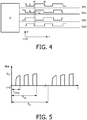
- the generator G is separately shown in Figure 4 together with exemplary control voltages VP1, VN1, VP2, VN2 for the transistors.
- the transistors M1 and M2 are NMOS transistors which conduct when their gate potential VN1 or VN2, respectively, is "high” (i.e. larger than their threshold voltage; usually the gates switch between 0 and the battery voltage Vb).
- the transistors M3 and M4 are PMOST transistors which conduct when their gate potential VP1 and VP2, respectively, is "low” (i.e. usually connected to ground).
- the implant I further comprises a connector C in which the output terminals TO1, TO2 of the supply module SM reversibly contact power input terminals TI1, TI2, respectively, of a "consumer module" CM.
- the connector C is typically not perfectly sealed and will hence allow the entrance of (conductive) moisture leading to a leakage current between the terminals. This is represented in Figure 2 by a leakage resistance R lk .
- the already mentioned consumer module CM comprises an AC-DC converter with a bridge comprising four diodes D1-D4 and a hold capacitor C h .
- the diode bridge rectifies the AC voltage provided by the power input terminals TI1, TI2.
- the hold capacitor C h can be made small because it has only to supply energy to the electronics during the switching transients when the (synchronous) rectifier does not deliver any power. Thus almost no precious implant volume needs to be sacrificed.
- the DC output voltage of the diode rectifier D1-D4 is further provided to power-consuming electronic circuits EC in which the proper functionality of the implant is realized (e.g. the scheduled delivery of stimulation pulses to neural tissue).
- the dissipated power of the electronic circuits EC of the implant's electronics is modeled by a resistor Re with a voltage (Ve+,Ve-) across it.
- a (full wave) synchronous rectifier which has a much smaller voltage drop, can be applied to improve the overall power efficiency.
- Such a rectifier can substantially be described as comprising an additional transistor in parallel with each diode which is switched on when current starts flowing through the diode (cf. M. I. Mihaiu: "Toward the 'Ideal Diode' using power MOSFET in full wave synchronous rectifiers for low voltage power supplies", SPEEDAM 2008, International Symposium on Power Electronics, Electrical Drives, Automation and Motion ).
- FIG. 5 illustrates a typical output voltage appearing at one power output terminal TO1 of the circuit of Figure 2 in a "pulsed operating mode" of the generator G.
- Said output voltage comprises a train of rectangular pulses that are repeated with a frequency 1/T chop .
- the train of pulses is provided during a charging phase T Ch , which is followed by a phase of inactivity in which the full-bridge power stage is not switching (for example, the power stage could be set in a state in which the power output terminals TO1, TO2 are not connected to either the battery B or ground (i.e. all transistors are not conducting), the output terminals TO1, TO2 are both connected to ground or both connected to the battery B).
- T p After the duration of one power transfer cycle, T p , a new train of charging pulses follows.
- the hold capacitor C h in the consumer module CM can very quickly be charged with a small time constant ⁇ Ch , while the hold capacitor is discharged by the electronics EC with a much larger time constant ⁇ e (R e C h ).
- the chopping period T chop can be taken to be a few charging time constants ⁇ Ch , and after a few chopping periods, during a time T Ch ⁇ T chop , the hold capacitor C h will be fully charged (because this will take approximately 5 charging time constants).
- the chopping period T chop can also be taken smaller than a single time constant ⁇ Ch (which can happen for a high chopping frequency), in which case the hold capacitor C h is only slightly charged during each chopping period. Nevertheless, if the active charging time T Ch is taken sufficiently long i.e. a sufficient number of time constants ⁇ Ch , the hold capacitor will still be fully charged.
- the chopping period can be chosen independently from the time constant ⁇ Ch .
- the power transfer period T p should preferably be taken much larger than the active charging time T Ch (often a few chopping periods T chop of each a few charging time constants ⁇ ch ) but also much smaller than the discharge time constant ⁇ e , i.e. T Ch ⁇ T p ⁇ ⁇ e .
- the chopping frequency is typically in the range between tens of Hz to a few kHz.
- the hold capacitor will be the sole energy source for the "consumer module" once the chopping stops.
- the chopping frequency low (e.g. 100 Hz, as without duty-cycling) and also would like to comply with T ch ⁇ T p (to reduce the effect of leakage current on the efficiency), one might end up with a quite large hold capacitor C h .
- the power transfer time T p to about 100 ⁇ s
- choose the active charging time T ch to be 10 ⁇ s (assuming this is sufficient to recharge the hold capacitor completely)
- take a chopping frequency e.g. 200 kHz (resulting in two chopping periods in the active charging time).
- the efficiency of the converter for an ideal rectifier can be calculated from ⁇ ⁇ V e V b 1 ⁇ T chop 4 ⁇ be 2 which shows that without hold capacitor, the highest efficiency is achieved.
- the blocking capacitor effectively replaces the hold capacitor. It should be noted that a small hold capacitor is still needed to supply the electronics during the switching transients.
- Duty-cycling can be applied to reduce the effect of leakage currents again, although the circuit behaves differently when a blocking capacitor is inserted.
- all transistors of the full-bridge power stage should be made non-conducting (i.e. all transistor switches are "open") after the chopping period T Ch for the remainder of the power transfer period T p to prevent current flow in the connector.
- grounding the outputs of the full-bridge power stage i.e. switching on M1 and M2 and switching off M3 and M4
- grounding would lead to a flow of a (discharge) current in the connector when a blocking capacitor were present (as in the circuit of Fig. 3 ).
- the blocking capacitor cannot act as hold capacitor in the pulsed power mode and the hold capacitor takes over this role again.
- the invention can favorably be applied in an implant, for example a deep brain stimulator, in which moisture should be allowed to enter (almost unavoidable during surgery) and a safe connection (i.e. no risk of electrolysis) has to be made between battery and electronics (both hermetically sealed) to make the battery replaceable.
- a safe connection i.e. no risk of electrolysis
- battery and electronics both hermetically sealed
Landscapes
- Health & Medical Sciences (AREA)
- Engineering & Computer Science (AREA)
- Public Health (AREA)
- Veterinary Medicine (AREA)
- Radiology & Medical Imaging (AREA)
- Life Sciences & Earth Sciences (AREA)
- Animal Behavior & Ethology (AREA)
- General Health & Medical Sciences (AREA)
- Biomedical Technology (AREA)
- Nuclear Medicine, Radiotherapy & Molecular Imaging (AREA)
- Power Engineering (AREA)
- Charge And Discharge Circuits For Batteries Or The Like (AREA)
- Electrotherapy Devices (AREA)
- Dc-Dc Converters (AREA)
- Direct Current Feeding And Distribution (AREA)
- Heart & Thoracic Surgery (AREA)
- Neurology (AREA)
Priority Applications (1)
| Application Number | Priority Date | Filing Date | Title |
|---|---|---|---|
| EP10752394.6A EP2453976B1 (en) | 2009-07-15 | 2010-06-30 | Apparatus with internal power transfer and method for internal power transfer |
Applications Claiming Priority (3)
| Application Number | Priority Date | Filing Date | Title |
|---|---|---|---|
| EP09165520 | 2009-07-15 | ||
| PCT/IB2010/052987 WO2011007281A1 (en) | 2009-07-15 | 2010-06-30 | Apparatus with internal power transfer |
| EP10752394.6A EP2453976B1 (en) | 2009-07-15 | 2010-06-30 | Apparatus with internal power transfer and method for internal power transfer |
Publications (2)
| Publication Number | Publication Date |
|---|---|
| EP2453976A1 EP2453976A1 (en) | 2012-05-23 |
| EP2453976B1 true EP2453976B1 (en) | 2019-03-13 |
Family
ID=43034165
Family Applications (1)
| Application Number | Title | Priority Date | Filing Date |
|---|---|---|---|
| EP10752394.6A Active EP2453976B1 (en) | 2009-07-15 | 2010-06-30 | Apparatus with internal power transfer and method for internal power transfer |
Country Status (7)
| Country | Link |
|---|---|
| US (1) | US9278225B2 (enExample) |
| EP (1) | EP2453976B1 (enExample) |
| JP (1) | JP6040027B2 (enExample) |
| CN (1) | CN102470242B (enExample) |
| BR (1) | BR112012000695B1 (enExample) |
| RU (1) | RU2555116C2 (enExample) |
| WO (1) | WO2011007281A1 (enExample) |
Families Citing this family (11)
| Publication number | Priority date | Publication date | Assignee | Title |
|---|---|---|---|---|
| JP2715412B2 (ja) | 1987-06-15 | 1998-02-18 | カシオ計算機株式会社 | メロディ分析機能付音楽装置及び自動作曲機 |
| JP2615722B2 (ja) | 1987-12-24 | 1997-06-04 | カシオ計算機株式会社 | 自動作曲機 |
| JP2621266B2 (ja) | 1987-12-24 | 1997-06-18 | カシオ計算機株式会社 | 自動作曲機 |
| JP2615720B2 (ja) | 1987-12-24 | 1997-06-04 | カシオ計算機株式会社 | 自動作曲機 |
| JP2689257B2 (ja) | 1988-05-25 | 1997-12-10 | カシオ計算機株式会社 | 自動作曲機 |
| JP2759110B2 (ja) | 1996-11-05 | 1998-05-28 | カシオ計算機株式会社 | 自動作曲機 |
| US20120215308A1 (en) * | 2011-02-17 | 2012-08-23 | Mathew Ross Markey | Power transfer in a medical implant |
| JP5256432B1 (ja) * | 2012-06-27 | 2013-08-07 | 東洋システム株式会社 | フルブリッジ電力変換装置 |
| US10238876B2 (en) * | 2015-09-04 | 2019-03-26 | Medtronic, Inc. | Stimulation aggressor management for biomedical signal acquisition systems |
| EP3499669A1 (en) | 2017-12-13 | 2019-06-19 | Ovh | Circuit and system implementing a smart fuse for a power supply |
| US10700603B2 (en) | 2017-12-13 | 2020-06-30 | Ovh | Circuit and system implementing a power supply configured for spark prevention |
Citations (2)
| Publication number | Priority date | Publication date | Assignee | Title |
|---|---|---|---|---|
| US4516820A (en) * | 1983-01-27 | 1985-05-14 | The Commonwealth Of Australia | Cochlear prosthesis package connector |
| EP0398722A2 (en) * | 1989-05-18 | 1990-11-22 | Hirotami Nakano | Uninterruptable power supply apparatus and isolating method thereof |
Family Cites Families (19)
| Publication number | Priority date | Publication date | Assignee | Title |
|---|---|---|---|---|
| US3888260A (en) | 1972-06-28 | 1975-06-10 | Univ Johns Hopkins | Rechargeable demand inhibited cardiac pacer and tissue stimulator |
| SE435679B (sv) | 1980-09-17 | 1984-10-15 | Landskrona Finans Ab | Stimulatorsystem, innefattande en av ett uppladdningsbart batteri driven pulsgenerator |
| US4523269A (en) * | 1983-11-16 | 1985-06-11 | Reliance Electric Company | Series resonance charge transfer regulation method and apparatus |
| US5027264A (en) * | 1989-09-29 | 1991-06-25 | Wisconsin Alumni Research Foundation | Power conversion apparatus for DC/DC conversion using dual active bridges |
| US5115386A (en) * | 1990-10-15 | 1992-05-19 | Hitachi, Ltd. | Circuit for controlling an electric power supply apparatus, a method therefor and an uninterruptible power supply |
| EP0999874B1 (en) * | 1997-08-01 | 2004-09-29 | Alfred E. Mann Foundation For Scientific Research | Implantable device with improved battery recharging and powering configuration |
| EP1424098B1 (en) * | 1997-08-01 | 2008-12-03 | Alfred E. Mann Foundation For Scientific Research | Implantable device with improved battery recharging and powering configuration |
| US6308101B1 (en) * | 1998-07-31 | 2001-10-23 | Advanced Bionics Corporation | Fully implantable cochlear implant system |
| US5948006A (en) | 1998-10-14 | 1999-09-07 | Advanced Bionics Corporation | Transcutaneous transmission patch |
| US6678559B1 (en) * | 1999-03-23 | 2004-01-13 | Medtronic, Inc. | Implantable medical device having a capacitor assembly with liner |
| US6516227B1 (en) | 1999-07-27 | 2003-02-04 | Advanced Bionics Corporation | Rechargeable spinal cord stimulator system |
| RU2213586C2 (ru) * | 2000-10-20 | 2003-10-10 | Каган Марк Яковлевич | Устройство подзарядки имплантируемого аккумулятора кардиостимулятора |
| SE523457C2 (sv) * | 2001-05-17 | 2004-04-20 | Abb Ab | VSC-strömriktare flrsedd med resonanskrets för kommuntering, jämte tillhörande förfarande, datorprogramprodukt och datorläsbart medium |
| US7211351B2 (en) | 2003-10-16 | 2007-05-01 | Cymbet Corporation | Lithium/air batteries with LiPON as separator and protective barrier and method |
| US7337010B2 (en) | 2004-10-29 | 2008-02-26 | Medtronic, Inc. | Medical device having lithium-ion battery |
| US7199535B2 (en) * | 2005-01-26 | 2007-04-03 | General Motors Corporation | Doubled-ended inverter drive system topology for a hybrid vehicle |
| KR100547289B1 (ko) * | 2005-05-18 | 2006-01-26 | 주식회사 피에스텍 | 간헐 모드로 동작하는 동기 정류형 직렬 공진 컨버터 |
| JP4436843B2 (ja) * | 2007-02-07 | 2010-03-24 | 株式会社日立製作所 | 電力変換装置 |
| US8295941B2 (en) * | 2008-09-15 | 2012-10-23 | The Invention Science Fund I, Llc | Systems configured to power at least one device disposed in a living subject, and related apparatuses and methods |
-
2010
- 2010-06-30 CN CN201080031536.XA patent/CN102470242B/zh active Active
- 2010-06-30 BR BR112012000695A patent/BR112012000695B1/pt active IP Right Grant
- 2010-06-30 WO PCT/IB2010/052987 patent/WO2011007281A1/en not_active Ceased
- 2010-06-30 RU RU2012105306/14A patent/RU2555116C2/ru active
- 2010-06-30 JP JP2012520130A patent/JP6040027B2/ja active Active
- 2010-06-30 EP EP10752394.6A patent/EP2453976B1/en active Active
- 2010-06-30 US US13/383,601 patent/US9278225B2/en active Active
Patent Citations (2)
| Publication number | Priority date | Publication date | Assignee | Title |
|---|---|---|---|---|
| US4516820A (en) * | 1983-01-27 | 1985-05-14 | The Commonwealth Of Australia | Cochlear prosthesis package connector |
| EP0398722A2 (en) * | 1989-05-18 | 1990-11-22 | Hirotami Nakano | Uninterruptable power supply apparatus and isolating method thereof |
Also Published As
| Publication number | Publication date |
|---|---|
| JP6040027B2 (ja) | 2016-12-07 |
| RU2555116C2 (ru) | 2015-07-10 |
| JP2012533330A (ja) | 2012-12-27 |
| US20120120684A1 (en) | 2012-05-17 |
| BR112012000695B1 (pt) | 2020-04-07 |
| CN102470242B (zh) | 2017-08-29 |
| BR112012000695A2 (pt) | 2016-11-16 |
| RU2012105306A (ru) | 2013-08-20 |
| CN102470242A (zh) | 2012-05-23 |
| EP2453976A1 (en) | 2012-05-23 |
| WO2011007281A1 (en) | 2011-01-20 |
| US9278225B2 (en) | 2016-03-08 |
Similar Documents
| Publication | Publication Date | Title |
|---|---|---|
| EP2453976B1 (en) | Apparatus with internal power transfer and method for internal power transfer | |
| JP2012533330A5 (enExample) | ||
| US10668296B2 (en) | Device and method for generating electrical stimulation | |
| US9814882B2 (en) | Rechargeable-battery implantable medical device having a primary battery active during a rechargeable-battery undervoltage condition | |
| US11197990B2 (en) | Systems and methods for transcutaneous power transfer using microneedles | |
| AU2004207413B2 (en) | Improved hybrid battery power source for implantable medical device | |
| EP2072080B1 (en) | Battery protection and zero-volt battery recovery system for an implantable medical device | |
| EP0047822B1 (en) | Stimulator system | |
| US9401625B2 (en) | Solar-powered external charger and solar-powered external charger cradle for medical implantable device systems | |
| AU2010306068B2 (en) | Method of power and data transfer in implantable electronic devices | |
| US6760618B1 (en) | Iontophoresis system | |
| JPH11506646A (ja) | 埋込み可能な医療装置のための経皮膚エネルギ伝送回路 | |
| WO2000065682A1 (en) | Self contained transportable power source maintenance and charge system | |
| EP1295624B1 (en) | Implantable energy management system | |
| US20040064084A1 (en) | Iontophoresis system | |
| US20240082591A1 (en) | Implantable Pulse Generator Having a Pulse Generation Device | |
| CN104826232A (zh) | 一种心脏起搏器振动供能系统 | |
| KR20090122674A (ko) | 압전소자를 사용한 삽입형 제세동기의 전원 공급 장치 및삽입형 제세동기 | |
| AU2009271914A1 (en) | AC logic powered stimulator IC for neural prosthesis | |
| KR101872882B1 (ko) | 구동전류 절감을 위한 방전회로를 포함하는 제세동기 및 이의 구동방법 | |
| US8615303B2 (en) | Power transfer to a medical implant located adjacent to tissue while preventing short circuits through the tissue | |
| Latha et al. | A novel transcutaneous energy transfer technique for biomedical implants | |
| JPS6223333A (ja) | 電池寿命警告装置 | |
| Kelly et al. | ISSCC 2004/SESSION 12/BIOMICROSYSTEMS/12.6 |
Legal Events
| Date | Code | Title | Description |
|---|---|---|---|
| PUAI | Public reference made under article 153(3) epc to a published international application that has entered the european phase |
Free format text: ORIGINAL CODE: 0009012 |
|
| 17P | Request for examination filed |
Effective date: 20120215 |
|
| AK | Designated contracting states |
Kind code of ref document: A1 Designated state(s): AL AT BE BG CH CY CZ DE DK EE ES FI FR GB GR HR HU IE IS IT LI LT LU LV MC MK MT NL NO PL PT RO SE SI SK SM TR |
|
| DAX | Request for extension of the european patent (deleted) | ||
| RAP1 | Party data changed (applicant data changed or rights of an application transferred) |
Owner name: KONINKLIJKE PHILIPS N.V. |
|
| 17Q | First examination report despatched |
Effective date: 20150414 |
|
| STAA | Information on the status of an ep patent application or granted ep patent |
Free format text: STATUS: EXAMINATION IS IN PROGRESS |
|
| GRAP | Despatch of communication of intention to grant a patent |
Free format text: ORIGINAL CODE: EPIDOSNIGR1 |
|
| STAA | Information on the status of an ep patent application or granted ep patent |
Free format text: STATUS: GRANT OF PATENT IS INTENDED |
|
| INTG | Intention to grant announced |
Effective date: 20180927 |
|
| GRAS | Grant fee paid |
Free format text: ORIGINAL CODE: EPIDOSNIGR3 |
|
| GRAA | (expected) grant |
Free format text: ORIGINAL CODE: 0009210 |
|
| STAA | Information on the status of an ep patent application or granted ep patent |
Free format text: STATUS: THE PATENT HAS BEEN GRANTED |
|
| AK | Designated contracting states |
Kind code of ref document: B1 Designated state(s): AL AT BE BG CH CY CZ DE DK EE ES FI FR GB GR HR HU IE IS IT LI LT LU LV MC MK MT NL NO PL PT RO SE SI SK SM TR |
|
| REG | Reference to a national code |
Ref country code: GB Ref legal event code: FG4D |
|
| REG | Reference to a national code |
Ref country code: CH Ref legal event code: EP Ref country code: AT Ref legal event code: REF Ref document number: 1106880 Country of ref document: AT Kind code of ref document: T Effective date: 20190315 |
|
| REG | Reference to a national code |
Ref country code: IE Ref legal event code: FG4D |
|
| REG | Reference to a national code |
Ref country code: DE Ref legal event code: R096 Ref document number: 602010057550 Country of ref document: DE |
|
| REG | Reference to a national code |
Ref country code: NL Ref legal event code: MP Effective date: 20190313 |
|
| REG | Reference to a national code |
Ref country code: LT Ref legal event code: MG4D |
|
| PG25 | Lapsed in a contracting state [announced via postgrant information from national office to epo] |
Ref country code: NO Free format text: LAPSE BECAUSE OF FAILURE TO SUBMIT A TRANSLATION OF THE DESCRIPTION OR TO PAY THE FEE WITHIN THE PRESCRIBED TIME-LIMIT Effective date: 20190613 Ref country code: SE Free format text: LAPSE BECAUSE OF FAILURE TO SUBMIT A TRANSLATION OF THE DESCRIPTION OR TO PAY THE FEE WITHIN THE PRESCRIBED TIME-LIMIT Effective date: 20190313 Ref country code: FI Free format text: LAPSE BECAUSE OF FAILURE TO SUBMIT A TRANSLATION OF THE DESCRIPTION OR TO PAY THE FEE WITHIN THE PRESCRIBED TIME-LIMIT Effective date: 20190313 Ref country code: LT Free format text: LAPSE BECAUSE OF FAILURE TO SUBMIT A TRANSLATION OF THE DESCRIPTION OR TO PAY THE FEE WITHIN THE PRESCRIBED TIME-LIMIT Effective date: 20190313 |
|
| PG25 | Lapsed in a contracting state [announced via postgrant information from national office to epo] |
Ref country code: LV Free format text: LAPSE BECAUSE OF FAILURE TO SUBMIT A TRANSLATION OF THE DESCRIPTION OR TO PAY THE FEE WITHIN THE PRESCRIBED TIME-LIMIT Effective date: 20190313 Ref country code: HR Free format text: LAPSE BECAUSE OF FAILURE TO SUBMIT A TRANSLATION OF THE DESCRIPTION OR TO PAY THE FEE WITHIN THE PRESCRIBED TIME-LIMIT Effective date: 20190313 Ref country code: NL Free format text: LAPSE BECAUSE OF FAILURE TO SUBMIT A TRANSLATION OF THE DESCRIPTION OR TO PAY THE FEE WITHIN THE PRESCRIBED TIME-LIMIT Effective date: 20190313 Ref country code: BG Free format text: LAPSE BECAUSE OF FAILURE TO SUBMIT A TRANSLATION OF THE DESCRIPTION OR TO PAY THE FEE WITHIN THE PRESCRIBED TIME-LIMIT Effective date: 20190613 Ref country code: GR Free format text: LAPSE BECAUSE OF FAILURE TO SUBMIT A TRANSLATION OF THE DESCRIPTION OR TO PAY THE FEE WITHIN THE PRESCRIBED TIME-LIMIT Effective date: 20190614 |
|
| REG | Reference to a national code |
Ref country code: AT Ref legal event code: MK05 Ref document number: 1106880 Country of ref document: AT Kind code of ref document: T Effective date: 20190313 |
|
| PG25 | Lapsed in a contracting state [announced via postgrant information from national office to epo] |
Ref country code: ES Free format text: LAPSE BECAUSE OF FAILURE TO SUBMIT A TRANSLATION OF THE DESCRIPTION OR TO PAY THE FEE WITHIN THE PRESCRIBED TIME-LIMIT Effective date: 20190313 Ref country code: EE Free format text: LAPSE BECAUSE OF FAILURE TO SUBMIT A TRANSLATION OF THE DESCRIPTION OR TO PAY THE FEE WITHIN THE PRESCRIBED TIME-LIMIT Effective date: 20190313 Ref country code: CZ Free format text: LAPSE BECAUSE OF FAILURE TO SUBMIT A TRANSLATION OF THE DESCRIPTION OR TO PAY THE FEE WITHIN THE PRESCRIBED TIME-LIMIT Effective date: 20190313 Ref country code: IT Free format text: LAPSE BECAUSE OF FAILURE TO SUBMIT A TRANSLATION OF THE DESCRIPTION OR TO PAY THE FEE WITHIN THE PRESCRIBED TIME-LIMIT Effective date: 20190313 Ref country code: RO Free format text: LAPSE BECAUSE OF FAILURE TO SUBMIT A TRANSLATION OF THE DESCRIPTION OR TO PAY THE FEE WITHIN THE PRESCRIBED TIME-LIMIT Effective date: 20190313 Ref country code: AL Free format text: LAPSE BECAUSE OF FAILURE TO SUBMIT A TRANSLATION OF THE DESCRIPTION OR TO PAY THE FEE WITHIN THE PRESCRIBED TIME-LIMIT Effective date: 20190313 Ref country code: PT Free format text: LAPSE BECAUSE OF FAILURE TO SUBMIT A TRANSLATION OF THE DESCRIPTION OR TO PAY THE FEE WITHIN THE PRESCRIBED TIME-LIMIT Effective date: 20190713 Ref country code: SK Free format text: LAPSE BECAUSE OF FAILURE TO SUBMIT A TRANSLATION OF THE DESCRIPTION OR TO PAY THE FEE WITHIN THE PRESCRIBED TIME-LIMIT Effective date: 20190313 |
|
| PG25 | Lapsed in a contracting state [announced via postgrant information from national office to epo] |
Ref country code: SM Free format text: LAPSE BECAUSE OF FAILURE TO SUBMIT A TRANSLATION OF THE DESCRIPTION OR TO PAY THE FEE WITHIN THE PRESCRIBED TIME-LIMIT Effective date: 20190313 Ref country code: PL Free format text: LAPSE BECAUSE OF FAILURE TO SUBMIT A TRANSLATION OF THE DESCRIPTION OR TO PAY THE FEE WITHIN THE PRESCRIBED TIME-LIMIT Effective date: 20190313 |
|
| REG | Reference to a national code |
Ref country code: DE Ref legal event code: R097 Ref document number: 602010057550 Country of ref document: DE |
|
| PG25 | Lapsed in a contracting state [announced via postgrant information from national office to epo] |
Ref country code: AT Free format text: LAPSE BECAUSE OF FAILURE TO SUBMIT A TRANSLATION OF THE DESCRIPTION OR TO PAY THE FEE WITHIN THE PRESCRIBED TIME-LIMIT Effective date: 20190313 Ref country code: IS Free format text: LAPSE BECAUSE OF FAILURE TO SUBMIT A TRANSLATION OF THE DESCRIPTION OR TO PAY THE FEE WITHIN THE PRESCRIBED TIME-LIMIT Effective date: 20190713 |
|
| PLBE | No opposition filed within time limit |
Free format text: ORIGINAL CODE: 0009261 |
|
| STAA | Information on the status of an ep patent application or granted ep patent |
Free format text: STATUS: NO OPPOSITION FILED WITHIN TIME LIMIT |
|
| PG25 | Lapsed in a contracting state [announced via postgrant information from national office to epo] |
Ref country code: DK Free format text: LAPSE BECAUSE OF FAILURE TO SUBMIT A TRANSLATION OF THE DESCRIPTION OR TO PAY THE FEE WITHIN THE PRESCRIBED TIME-LIMIT Effective date: 20190313 Ref country code: MC Free format text: LAPSE BECAUSE OF FAILURE TO SUBMIT A TRANSLATION OF THE DESCRIPTION OR TO PAY THE FEE WITHIN THE PRESCRIBED TIME-LIMIT Effective date: 20190313 |
|
| REG | Reference to a national code |
Ref country code: CH Ref legal event code: PL |
|
| 26N | No opposition filed |
Effective date: 20191216 |
|
| PG25 | Lapsed in a contracting state [announced via postgrant information from national office to epo] |
Ref country code: SI Free format text: LAPSE BECAUSE OF FAILURE TO SUBMIT A TRANSLATION OF THE DESCRIPTION OR TO PAY THE FEE WITHIN THE PRESCRIBED TIME-LIMIT Effective date: 20190313 |
|
| REG | Reference to a national code |
Ref country code: BE Ref legal event code: MM Effective date: 20190630 |
|
| PG25 | Lapsed in a contracting state [announced via postgrant information from national office to epo] |
Ref country code: TR Free format text: LAPSE BECAUSE OF FAILURE TO SUBMIT A TRANSLATION OF THE DESCRIPTION OR TO PAY THE FEE WITHIN THE PRESCRIBED TIME-LIMIT Effective date: 20190313 |
|
| PG25 | Lapsed in a contracting state [announced via postgrant information from national office to epo] |
Ref country code: IE Free format text: LAPSE BECAUSE OF NON-PAYMENT OF DUE FEES Effective date: 20190630 |
|
| PG25 | Lapsed in a contracting state [announced via postgrant information from national office to epo] |
Ref country code: CH Free format text: LAPSE BECAUSE OF NON-PAYMENT OF DUE FEES Effective date: 20190630 Ref country code: BE Free format text: LAPSE BECAUSE OF NON-PAYMENT OF DUE FEES Effective date: 20190630 Ref country code: LU Free format text: LAPSE BECAUSE OF NON-PAYMENT OF DUE FEES Effective date: 20190630 Ref country code: LI Free format text: LAPSE BECAUSE OF NON-PAYMENT OF DUE FEES Effective date: 20190630 |
|
| PG25 | Lapsed in a contracting state [announced via postgrant information from national office to epo] |
Ref country code: CY Free format text: LAPSE BECAUSE OF FAILURE TO SUBMIT A TRANSLATION OF THE DESCRIPTION OR TO PAY THE FEE WITHIN THE PRESCRIBED TIME-LIMIT Effective date: 20190313 |
|
| PG25 | Lapsed in a contracting state [announced via postgrant information from national office to epo] |
Ref country code: MT Free format text: LAPSE BECAUSE OF FAILURE TO SUBMIT A TRANSLATION OF THE DESCRIPTION OR TO PAY THE FEE WITHIN THE PRESCRIBED TIME-LIMIT Effective date: 20190313 Ref country code: HU Free format text: LAPSE BECAUSE OF FAILURE TO SUBMIT A TRANSLATION OF THE DESCRIPTION OR TO PAY THE FEE WITHIN THE PRESCRIBED TIME-LIMIT; INVALID AB INITIO Effective date: 20100630 |
|
| PG25 | Lapsed in a contracting state [announced via postgrant information from national office to epo] |
Ref country code: MK Free format text: LAPSE BECAUSE OF FAILURE TO SUBMIT A TRANSLATION OF THE DESCRIPTION OR TO PAY THE FEE WITHIN THE PRESCRIBED TIME-LIMIT Effective date: 20190313 |
|
| PGFP | Annual fee paid to national office [announced via postgrant information from national office to epo] |
Ref country code: DE Payment date: 20250626 Year of fee payment: 16 |
|
| PGFP | Annual fee paid to national office [announced via postgrant information from national office to epo] |
Ref country code: GB Payment date: 20250617 Year of fee payment: 16 |
|
| PGFP | Annual fee paid to national office [announced via postgrant information from national office to epo] |
Ref country code: FR Payment date: 20250624 Year of fee payment: 16 |