EP2452861A1 - Steering hanger beam structure - Google Patents
Steering hanger beam structure Download PDFInfo
- Publication number
- EP2452861A1 EP2452861A1 EP11189069A EP11189069A EP2452861A1 EP 2452861 A1 EP2452861 A1 EP 2452861A1 EP 11189069 A EP11189069 A EP 11189069A EP 11189069 A EP11189069 A EP 11189069A EP 2452861 A1 EP2452861 A1 EP 2452861A1
- Authority
- EP
- European Patent Office
- Prior art keywords
- stiffener
- column
- holder
- hanger beam
- steering hanger
- Prior art date
- Legal status (The legal status is an assumption and is not a legal conclusion. Google has not performed a legal analysis and makes no representation as to the accuracy of the status listed.)
- Granted
Links
Images

Classifications
-
- B—PERFORMING OPERATIONS; TRANSPORTING
- B62—LAND VEHICLES FOR TRAVELLING OTHERWISE THAN ON RAILS
- B62D—MOTOR VEHICLES; TRAILERS
- B62D25/00—Superstructure or monocoque structure sub-units; Parts or details thereof not otherwise provided for
- B62D25/08—Front or rear portions
- B62D25/14—Dashboards as superstructure sub-units
- B62D25/145—Dashboards as superstructure sub-units having a crossbeam incorporated therein
Definitions
- the present invention relates to a structure of a steering hanger beam which supports a steering column.
- a steering hanger beam for supporting a steering column is installed in the right-left direction of the vehicle inside of the instrument panel arranged in front of the driver's seat of the vehicle.
- the steering hanger beam which is laterally installed at the front part of the cabin and is connected to a vehicle body at its opposite ends, is formed to be a dual pipe structure comprising an inner pipe and an outer pipe over the substantially full length in the longitudinal direction of the steering hanger beam.
- the steering hanger beam structure disclosed in Unexamined Japanese Patent Application Publication No. 11-222157 has a problem that the weight of the steering hanger beam is significantly increased because the steering hanger beam is formed to be a dual pipe structure comprising an inner pipe and an outer pipe over the substantially full length in the longitudinal direction of the steering hanger beam. Further, a manufacturing process of the steering hanger beam having a dual pipe structure is complicated, and thus, a reinforcing structure has been desired which can more easily improve the rigidity of the steering hanger beam.
- the present invention has been made in view of these problems and an object of the present invention is to provide a steering hanger beam structure which can suppress the weight increase of the steering hanger beam and can more easily improve the rigidity of the steering hanger beam than the conventional steering hanger beam.
- a first aspect of the present invention provides a steering hanger beam structure including: a steering hanger beam extending in a vehicle width direction and connected to right and left vehicle body members; a column holder arranged on an intermediate part of the steering hanger beam in the vehicle width direction and supporting a steering column; and a stiffener which is formed of a press plate, wherein the stiffener includes: a stiffener main body extending in a direction away from a cross sectional center of the steering hanger beam; a vehicle-body-member-side connecting end portion which is one end of the stiffener main body in the vehicle width direction and is connected to the vehicle body member; a column-holder-side connecting end portion which is the other end of the stiffener main body in the vehicle width direction and is connected to the column holder; and a beam connecting end portion which is an end portion of the stiffener main body on a side of the steering hanger beam and is welded to an outer circumferential surface of the steering hanger beam.
- the stiffener further comprises a first flange portion which extends from an end of the stiffener opposite to the beam connecting end portion in a direction in which the first flange portion intersects with the stiffener main body.
- the first flange portion is provided over an entire length of the stiffener in a vehicle width direction and includes a column-holder-side inclined portion at an end of the first flange portion opposite to the stiffener main body, the column-holder-side inclined portion being inclined away from the stiffener main body as the column-holder-side inclined portion comes closer to the column holder.
- the first flange portion is provided over an entire length of the stiffener in the vehicle width direction and includes a vehicle-body-member-side inclined portion at an end of the first flange portion opposite to the stiffener main body, the vehicle-body-member-side inclined portion being inclined away from the stiffener main body as the vehicle-body-member-side inclined portion comes closer to the column holder.
- the stiffener is welded to the outer circumferential surface of the steering hanger beam such that the stiffener main body extend in a vehicle front-rear direction; and the stiffener includes a first flange portion which is provided over an entire length of the stiffener in the vehicle width direction and extends downward from an end of the stiffener opposite to the beam connecting end portion, and wherein the first flange portion includes at its lower end a column-holder-side inclined portion which is inclined downward as the column-holder-side inclined portion comes closer to the column holder and a vehicle-body-member-side inclined portion which is inclined downward as the vehicle-body-member-side inclined portion comes closer to the vehicle body member.
- the column holder includes a recessed cross section part which extends in a vehicle front-rear direction and opens upward, and the stiffener further includes a leg portion which covers an opened portion of the recessed cross section part to form a closed cross section together with the recessed cross section part.
- the column holder includes a recessed cross section part which extends in a vehicle front-rear direction and opens upward
- the stiffener further includes a leg portion which covers an opened portion of the recessed cross section part to form a closed cross section together with the recessed cross section part, and wherein the leg portion is formed to be continued to the column-holder-side inclined portion.
- the stiffener includes a second flange portion which extends from the column-holder-side connecting end portion such that the second flange portion intersects with the stiffener main body, and the column-holder-side connecting end portion is connected to the column holder via the second flange portion.
- the stiffener includes a bead extending in the vehicle width direction, the bead being formed over the stiffener main body and the second flange portion.
- FIG. 1 An embodiment of the present invention is described in detail with reference to Figs. 1 to 5 .
- the embodiment is described by taking as an example a case where the present invention is applied to a right-handle vehicle.
- similar components are assigned similar reference numerals, and repeated explanation thereof is omitted.
- a direction in the description the direction is based on the front-rear, right-left and up-down directions of a vehicle. Accordingly, a "vehicle width direction" and a "right-left direction” mean the same direction in the following description.
- a steering hanger beam structure 1 is a device which supports a steering column 2 and a steering wheel 3 and is arranged in an instrument panel (not shown) provided at the front part of a cabin as shown in Fig. 1 .
- the steering hanger beam structure 1 is mainly comprised of a steering hanger beam 10 which extends in the vehicle width direction, a column holder 20 which supports a steering column 2, and a stiffener 30 which is formed of a press plate.
- the steering hanger beam 10 is a pipe-like hollow member which is mounted across left and right vehicle body members and extends in the vehicle width direction.
- a left end part 10a of the steering hanger beam 10 is fixed to a front-passenger-side holder member 4 which is provided to the vehicle body member on the front passenger side.
- a right end part 10b of the steering hanger beam 10 is fixed to a driver-side holder member 5 provided to the vehicle body member on the driver side.
- the steering hanger beam 10 includes a first pipe member 11 disposed on the front passenger side and a second pipe member 12 disposed on the driver side and having a larger diameter than the first pipe member 11.
- the first pipe member 11 and the second pipe member 12 are integrally formed by a connecting means such as welding.
- a column holder 20 (described later) is fixed to the middle part of the second pipe member 12 on the driver side.
- a pair of knee bolsters 13,13 extend obliquely rear downward from the lower surface of the second pipe member 12 on the left and right sides of the column holder 20.
- the knee bolster 13 is a member for receiving a load from the knee of a passenger to suppress the frontward movement of the passenger when the front part of the vehicle is collided, for example.
- the steering hanger beam 10 is provided with a bracket or the like to which a globe box or a center panel are attached in addition to the components described above.
- the column holder 20 is a member which supports a steering column 2.
- the column holder 20 is attached to the lower side of the steering hanger beam 10 at an intermediate part of the steering hanger beam 10 in the vehicle width direction (More particularly, a little left to the middle of the second pipe member 12).
- the column holder 20 extends in the front-rear direction along the steering column 2.
- the column holder 20 includes a groove-like column mounting part 21 which opens downward; and recessed cross section parts 22R, 22L which are provided on the left and right sides of the column mounting part 21 and open upward.
- the column mounting part 21 is attached to the steering column 2 such that the column mounting part 21 is fit into the steering column 2.
- a beam mounting part 23 formed in a circular concave shape which corresponds to the shape of the lower surface of the second pipe member 12.
- the left side recessed cross section part 22L of the column holder 20 is connected to a front part vehicle body member such as an instrument panel or dashboard upper via a supporting stay (not shown).
- the stiffener 30 is a member which reinforces the steering hanger beam 10.
- the stiffener 30 is formed of a press plate which is formed by press forming a metallic plate such as a steel plate or an aluminum plate.
- the stiffener 30 is attached to a part of a front side outer circumferential surface of the second pipe member 12 from the driver-side holder member 5 to the column holder 20.
- the stiffener 30 mainly includes a plate-like stiffener main body 31 which extends obliquely front downward from the front outer circumferential surface of the second pipe member 12; a first flange portion 32 which extends downward from the front end portion 31a of the stiffener main body 31; a leg portion 33 provided to the first flange portion 32 on the side of the column holder 20; a second flange portion 34 extending downward from an end portion 31b of the stiffener main body 31 on the side of the column holder 20; and a bead 35 formed over a substantially entire part of the stiffener 30.
- the stiffener main body 31 is a plate like portion formed long in the right-left direction and having a rectangular shape in a plain view.
- the stiffener main body 31 includes a plurality of through-holes 31e which is mounting seats of electrical members (not shown).
- the stiffener main body 31 extend away from the cross-sectional center O of the second pipe member 12 (frontward in the embodiment)from the front outer circumferential surface of the second pipe member 12 in a cross sectional view as shown in Fig. 3 .
- the right end portion 31c of the stiffener main body 31 (may also be referred to as a "vehicle-body-member-side connecting end portion 31c", hereinafter) is welded to the driver-side holder member 5, for example, by mig welding.
- the end portion 31b of the stiffener main body 31(may also be referred to as a "column-holder-side connecting end portion 31b") on the side of the column holder 20 is connected to the upper surface of the column holder 20 via the second flange portion 34.
- a lower end portion 34a of the second flange portion 34 is welded to the upper surface of the column holder 20, for example, by mig welding.
- An end portion 31d (may also be referred to as a "beam connecting end portion 31d", hereinafter) of the stiffener main body 31 on the side of the steering hanger beam 10 extends along the second pipe member 12 in the right-left direction and is welded to the outer circumferential surface of the second pipe member 12, for example, by mig welding.
- the first flange portion 32 is a wall like portion which extends downward from the front end portion 31a of the stiffener main body 31.
- the first flange portion 32 is formed to be bent such that the first flange portion 32 is substantially perpendicular to the stiffener main body 31.
- a right end portion 32a of the first flange portion 32 is welded to the driver-side holder member 5, for example, by mig welding.
- the part around the left end portion 32b of the first flange portion 32 is positioned above the right side recessed cross section part22R of the column holder 20 and forms a wall portion 32c which connects the stiffener main body 31 and the leg portion 33.
- a portion 32e (may also be referred to as “vehicle-body-member side inclination portion 32e") on the side of the driver-side holder member 5 in the lower end portion 32d of the first flange portion 32 which is an end opposite to the stiffener main body 31 is inclined away from the stiffener main body 31 as the portion 32e comes closer to the driver-side holder member 5.
- a part 32f (may also be referred to as “column-holder side inclination part 32f”) on the side of the column holder 20 in the lower end portion 32d of the first flange portion 32 is inclined away from the stiffener main body 31 as the part 32f comes closer to the column holder 20 (more particularly, the wall portion 32c).
- the lower end portion 32d of the first flange portion 32 are formed in an upside down U-like curved shape in which the left and right ends of the lower end portion 32d are positioned lower than the center part thereof.
- the lower end portion 32d of the first flange portion 32 is provided with two protrusions 32g, 32g (see Fig. 5 ) each including a through-hole and arranged with some space therebetween.
- the leg portion 33 extends frontward from the lower end portion of the wall portion 32c of the first flange portion 32. In short, the leg portion 33 is continued to the column-holder side inclination part 32f via the wall portion 32c. The leg portion 33 is fit into the right side recessed cross section part22R of the column holder 20. As shown in Fig. 4 , the leg portion 33 is arranged above a bottom portion 22Ra of the recessed cross section part 22R with some space between the leg portion 33 and the bottom portion 22Ra. Left and right side portions 33a, 33b of the leg portion 33 are respectively welded to left and right inner walls 22Rb, 22Rc of the recessed cross section part 22R, for example, by mig welding. Accordingly, a closed cross sectional surface K is formed by the leg portion 33 and the recessed cross section part22R.
- the second flange portion 34 is a wall-like portion extending downward from the end portion 31b of the stiffener main body 31 on the side of the column holder 20.
- the second flange portion 34 is formed to be bent such that the second flange portion 34 is perpendicular to both of the stiffener main body 31 and the first flange portion 32.
- the lower end portion 34a of the second flange portion 34 is welded to the upper surface of the column holder 20, for example, by mig welding.
- the front end portion of the second flange portion 34 is spaced from the first flange portion 32 and a rear end portion of the second flange portion 34 is spaced from the outer circumferential surface of the second pipe member 12.
- the bead 35 is a reinforcing structure for increasing the rigidity of the stiffener 30.
- the bead 35 is formed by press forming a press plate in such a shape that the upper surface of the bead 35 is recessed and the back surface of the bead 35 is protruded, as shown in Fig. 3 . As shown in Fig.
- the bead 35 includes a first bead portion 35a which extend in the right-left direction along the edge of the upper surface of the stiffener main body 31 on the side of the steering hanger beam 10; a second bead portion 35b formed to be curved frontward continuously from the first bead portion 35a in the vicinity of the end portion 31c of the stiffener main body 31; a third bead portion 35c which is formed to be bent frontward from the first bead portion 35a in the vicinity of the end portion 31b of the stiffener main body 31 on the side of the column holder 20 and is formed to be wider than the first bead portion 35a; a fourth bead portion 35d which is continued to the upper surface of the leg portion 33 from the third bead portion 35c through the wall portion 32c; and a fifth bead portion 35e formed over the surface of the second flange portion 34 from the third bead portion 35c.
- the steering hanger beam structure 1 according to the embodiment is formed as described above and effects of the steering hanger beam structure 1 is described below with reference to Figs. 1 to 5 .
- the stiffener 30 is formed of a press plate and is arranged between the driver-side holder member 5 and the column holder 20, it is possible to suppress the weight increase of the vehicle body compared with a conventional reinforced structure in which a steering hanger beam is formed in a double-pipe structure in the entire length of the steering hanger beam.
- the stiffener 30 is welded to the driver-side holder member 5, the column holder 20 and the steering hanger beam 10 and the stiffener main body 31 extend in a direction away from the cross-sectional center O of the steering hanger beam 10 (frontward in the embodiment), it is possible to secure the rigidity of the steering hanger beam 10. Especially, it is possible to obtain the strength and rigidity to a load which acts to bend the steering hanger beam 10 or change the cross sectional shape of the steering hanger beam 10 in a direction substantially parallel to the stiffener main body 31 (i.e. the right-left direction).
- first flange portion 32 extend downward from the front end portion 31a of the stiffener main body 31, it is possible to obtain the strength and rigidity to a load which acts to bend the steering hanger beam 10 or change the cross sectional shape of the steering hanger beam 10 in the up-down direction.
- first flange portion 32 extend in the up-down direction and is formed in a curved shape in which the middle part of the lower end portion 32d is recessed upward by the column-holder side inclination part 32f and the vehicle-body-member side inclination portion 32e, it is possible to enhance the strength and rigidity to the downward bending deformation of the steering hanger beam 10 by the arch effect of the first flange portion 32. Therefore, it is possible to suppress the deformation of the steering hanger beam 10 by the weight of the steering column 2 and the steering wheel 3.
- the closed cross sectional surface K is formed by the leg portion 33 of the stiffener 30 and the recessed cross section part 22R of the column holder 20, it is possible to further improve the strength and the rigidity to the bending or deformation of the steering hanger beam 10.
- the column-holder side inclination part 32f is formed between the first flange portion 32 and the leg portion 33, it is possible to suppress the rapid shape change (bending) of the part between the first flange portion 32 and the leg portion 33 and to alleviate the concentration of the stress to the leg portion 33.
- the faces of the stiffener 30 in three directions are formed to be boxed shape by the stiffener main body 31, the first flange portion 32 and the second flange portion 34, it is possible to further improve the strength and rigidity of the stiffener 30.
- the stiffener 30 includes the bead 35 extending in the vehicle width direction and the bead 35 is formed over the stiffener main body 31 and the leg portion 33 and over the stiffener main body 31 and the second flange portion 34, it is possible to further enhance the strength and the rigidity to the deformation of the stiffener 30 in the direction outside of the faces of the stiffener.
- a steering hanger beam structure can be realized which can suppress the weight increase of the steering hanger beam structure and can more easily improve the rigidity of the steering hanger beam structure than a conventional steering hanger beam structure.
- the stiffener 30 is attached to the front side of the steering hanger beam 10 in the embodiment, however, the present invention is not limited to this and the stiffener 30 may be attached to the front-rear or up-down direction depending on the direction in which the strength and the rigidity are to be improved.
- front-passenger-side holder member 4 and the driver-side holder member 5 are illustrated in the embodiment as left and right vehicle body members to which the steering hanger beam 10 is attached, however, the present invention is not limited to this.
- the steering hanger beam 10 may be directly attached to a vehicle body member such as a front pillar or an inner panel appropriately.
- a steering hanger beam structure 1 includes a steering hanger beam 10 extending in a vehicle width direction, a column holder 20 which supports a steering column 2, and a stiffener 30 formed of a press plate.
- the stiffener 30 includes a stiffener main body extending front downward from the front outer circumferential surface of the second pipe member 12, a vehicle-body-member-side connecting end portion 31c which is connected to the driver-side holder member 5, a column-holder-side connecting end portion 31b which is connected to the column holder 20; and a beam connecting end portion 31d which is connected to the outer circumferential surface of the steering hanger beam 10.
Landscapes
- Engineering & Computer Science (AREA)
- Chemical & Material Sciences (AREA)
- Combustion & Propulsion (AREA)
- Transportation (AREA)
- Mechanical Engineering (AREA)
- Body Structure For Vehicles (AREA)
Abstract
Description
- The present invention relates to a structure of a steering hanger beam which supports a steering column.
- Conventionally, a steering hanger beam for supporting a steering column is installed in the right-left direction of the vehicle inside of the instrument panel arranged in front of the driver's seat of the vehicle. For example, Unexamined Japanese Patent Application Publication No.
11-222157 - The steering hanger beam structure disclosed in Unexamined Japanese Patent Application Publication No.
11-222157 - The present invention has been made in view of these problems and an object of the present invention is to provide a steering hanger beam structure which can suppress the weight increase of the steering hanger beam and can more easily improve the rigidity of the steering hanger beam than the conventional steering hanger beam.
- A first aspect of the present invention provides a steering hanger beam structure including: a steering hanger beam extending in a vehicle width direction and connected to right and left vehicle body members; a column holder arranged on an intermediate part of the steering hanger beam in the vehicle width direction and supporting a steering column; and a stiffener which is formed of a press plate, wherein the stiffener includes: a stiffener main body extending in a direction away from a cross sectional center of the steering hanger beam; a vehicle-body-member-side connecting end portion which is one end of the stiffener main body in the vehicle width direction and is connected to the vehicle body member; a column-holder-side connecting end portion which is the other end of the stiffener main body in the vehicle width direction and is connected to the column holder; and a beam connecting end portion which is an end portion of the stiffener main body on a side of the steering hanger beam and is welded to an outer circumferential surface of the steering hanger beam.
- In the aforementioned steering hanger beam structure, it is preferable that the stiffener further comprises a first flange portion which extends from an end of the stiffener opposite to the beam connecting end portion in a direction in which the first flange portion intersects with the stiffener main body.
- In the aforementioned steering hanger beam structure, it is preferable that the first flange portion is provided over an entire length of the stiffener in a vehicle width direction and includes a column-holder-side inclined portion at an end of the first flange portion opposite to the stiffener main body, the column-holder-side inclined portion being inclined away from the stiffener main body as the column-holder-side inclined portion comes closer to the column holder.
- In the aforementioned steering hanger beam structure, it is preferable that the first flange portion is provided over an entire length of the stiffener in the vehicle width direction and includes a vehicle-body-member-side inclined portion at an end of the first flange portion opposite to the stiffener main body, the vehicle-body-member-side inclined portion being inclined away from the stiffener main body as the vehicle-body-member-side inclined portion comes closer to the column holder.
- In the aforementioned steering hanger beam structure, it is preferable that the stiffener is welded to the outer circumferential surface of the steering hanger beam such that the stiffener main body extend in a vehicle front-rear direction; and the stiffener includes a first flange portion which is provided over an entire length of the stiffener in the vehicle width direction and extends downward from an end of the stiffener opposite to the beam connecting end portion, and wherein the first flange portion includes at its lower end a column-holder-side inclined portion which is inclined downward as the column-holder-side inclined portion comes closer to the column holder and a vehicle-body-member-side inclined portion which is inclined downward as the vehicle-body-member-side inclined portion comes closer to the vehicle body member.
- In the aforementioned steering hanger beam structure, it is preferable that the column holder includes a recessed cross section part which extends in a vehicle front-rear direction and opens upward, and the stiffener further includes a leg portion which covers an opened portion of the recessed cross section part to form a closed cross section together with the recessed cross section part.
- In the aforementioned steering hanger beam structure, it is preferable that the column holder includes a recessed cross section part which extends in a vehicle front-rear direction and opens upward, and the stiffener further includes a leg portion which covers an opened portion of the recessed cross section part to form a closed cross section together with the recessed cross section part, and wherein the leg portion is formed to be continued to the column-holder-side inclined portion.
- In the aforementioned steering hanger beam structure, it is preferable that the stiffener includes a second flange portion which extends from the column-holder-side connecting end portion such that the second flange portion intersects with the stiffener main body, and the column-holder-side connecting end portion is connected to the column holder via the second flange portion.
- In the aforementioned steering hanger beam structure, it is preferable that the stiffener includes a bead extending in the vehicle width direction, the bead being formed over the stiffener main body and the second flange portion.
-
-
Fig. 1 is a plain view of a steering hanger beam structure according to an embodiment of the present invention. -
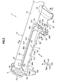
Fig. 2 is a perspective view showing a stiffener attached to the steering hanger beam seen downward from the left front side of the stiffener. -
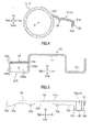
Fig. 3 is a cross sectional view along the line I-I shown inFig. 2 . -
Fig. 4 is a cross sectional view along the line □-□ shown inFig. 2 . -
Fig. 5 is a front view of the stiffener seen in the direction X shown inFig. 2 . - An embodiment of the present invention is described in detail with reference to
Figs. 1 to 5 . The embodiment is described by taking as an example a case where the present invention is applied to a right-handle vehicle. In the following description, similar components are assigned similar reference numerals, and repeated explanation thereof is omitted. When indicating a direction in the description, the direction is based on the front-rear, right-left and up-down directions of a vehicle. Accordingly, a "vehicle width direction" and a "right-left direction" mean the same direction in the following description. - A steering hanger beam structure 1 according to the embodiment is a device which supports a steering column 2 and a steering wheel 3 and is arranged in an instrument panel (not shown) provided at the front part of a cabin as shown in
Fig. 1 . The steering hanger beam structure 1 is mainly comprised of asteering hanger beam 10 which extends in the vehicle width direction, acolumn holder 20 which supports a steering column 2, and astiffener 30 which is formed of a press plate. - As shown in
Fig. 1 , thesteering hanger beam 10 is a pipe-like hollow member which is mounted across left and right vehicle body members and extends in the vehicle width direction. Aleft end part 10a of thesteering hanger beam 10 is fixed to a front-passenger-side holder member 4 which is provided to the vehicle body member on the front passenger side. Further, aright end part 10b of thesteering hanger beam 10 is fixed to a driver-side holder member 5 provided to the vehicle body member on the driver side. - The
steering hanger beam 10 includes afirst pipe member 11 disposed on the front passenger side and asecond pipe member 12 disposed on the driver side and having a larger diameter than thefirst pipe member 11. Thefirst pipe member 11 and thesecond pipe member 12 are integrally formed by a connecting means such as welding. A column holder 20 (described later) is fixed to the middle part of thesecond pipe member 12 on the driver side. A pair ofknee bolsters second pipe member 12 on the left and right sides of thecolumn holder 20. Theknee bolster 13 is a member for receiving a load from the knee of a passenger to suppress the frontward movement of the passenger when the front part of the vehicle is collided, for example. Although omitted in the accompanying drawings, thesteering hanger beam 10 is provided with a bracket or the like to which a globe box or a center panel are attached in addition to the components described above. - As shown in
Fig. 1 , thecolumn holder 20 is a member which supports a steering column 2. Thecolumn holder 20 is attached to the lower side of thesteering hanger beam 10 at an intermediate part of thesteering hanger beam 10 in the vehicle width direction (More particularly, a little left to the middle of the second pipe member 12). Thecolumn holder 20 extends in the front-rear direction along the steering column 2. - As shown in
Figs. 2 and4 , thecolumn holder 20 includes a groove-likecolumn mounting part 21 which opens downward; and recessedcross section parts column mounting part 21 and open upward. Thecolumn mounting part 21 is attached to the steering column 2 such that thecolumn mounting part 21 is fit into the steering column 2. Provided on the upper surface of thecolumn holder 20 is abeam mounting part 23 formed in a circular concave shape which corresponds to the shape of the lower surface of thesecond pipe member 12. Although not shown, the left side recessedcross section part 22L of thecolumn holder 20 is connected to a front part vehicle body member such as an instrument panel or dashboard upper via a supporting stay (not shown). - As shown in
Fig. 1 , thestiffener 30 is a member which reinforces thesteering hanger beam 10. Thestiffener 30 is formed of a press plate which is formed by press forming a metallic plate such as a steel plate or an aluminum plate. Thestiffener 30 is attached to a part of a front side outer circumferential surface of thesecond pipe member 12 from the driver-side holder member 5 to thecolumn holder 20. - As shown in
Figs. 2 and3 , thestiffener 30 mainly includes a plate-like stiffenermain body 31 which extends obliquely front downward from the front outer circumferential surface of thesecond pipe member 12; afirst flange portion 32 which extends downward from thefront end portion 31a of the stiffenermain body 31; aleg portion 33 provided to thefirst flange portion 32 on the side of thecolumn holder 20; asecond flange portion 34 extending downward from anend portion 31b of the stiffenermain body 31 on the side of thecolumn holder 20; and abead 35 formed over a substantially entire part of thestiffener 30. - The stiffener
main body 31 is a plate like portion formed long in the right-left direction and having a rectangular shape in a plain view. The stiffenermain body 31 includes a plurality of through-holes 31e which is mounting seats of electrical members (not shown). The stiffenermain body 31 extend away from the cross-sectional center O of the second pipe member 12 (frontward in the embodiment)from the front outer circumferential surface of thesecond pipe member 12 in a cross sectional view as shown inFig. 3 . - As shown in
Fig. 2 , theright end portion 31c of the stiffener main body 31(may also be referred to as a "vehicle-body-member-side connectingend portion 31c", hereinafter) is welded to the driver-side holder member 5, for example, by mig welding. Theend portion 31b of the stiffener main body 31(may also be referred to as a "column-holder-side connectingend portion 31b") on the side of thecolumn holder 20 is connected to the upper surface of thecolumn holder 20 via thesecond flange portion 34. Alower end portion 34a of thesecond flange portion 34 is welded to the upper surface of thecolumn holder 20, for example, by mig welding. Anend portion 31d (may also be referred to as a "beam connectingend portion 31d", hereinafter) of the stiffenermain body 31 on the side of thesteering hanger beam 10 extends along thesecond pipe member 12 in the right-left direction and is welded to the outer circumferential surface of thesecond pipe member 12, for example, by mig welding. - As shown in
Figs. 2 and5 , thefirst flange portion 32 is a wall like portion which extends downward from thefront end portion 31a of the stiffenermain body 31. In the embodiment, thefirst flange portion 32 is formed to be bent such that thefirst flange portion 32 is substantially perpendicular to the stiffenermain body 31. Aright end portion 32a of thefirst flange portion 32 is welded to the driver-side holder member 5, for example, by mig welding. The part around theleft end portion 32b of thefirst flange portion 32 is positioned above the right side recessed cross section part22R of thecolumn holder 20 and forms awall portion 32c which connects the stiffenermain body 31 and theleg portion 33. - A
portion 32e (may also be referred to as "vehicle-body-memberside inclination portion 32e") on the side of the driver-side holder member 5 in thelower end portion 32d of thefirst flange portion 32 which is an end opposite to the stiffenermain body 31 is inclined away from the stiffenermain body 31 as theportion 32e comes closer to the driver-side holder member 5. On the other hand, apart 32f (may also be referred to as "column-holderside inclination part 32f") on the side of thecolumn holder 20 in thelower end portion 32d of thefirst flange portion 32 is inclined away from the stiffenermain body 31 as thepart 32f comes closer to the column holder 20 (more particularly, thewall portion 32c). Thus, by forming the vehicle-body-memberside inclination portion 32e and the column-holderside inclination part 32f, thelower end portion 32d of thefirst flange portion 32 are formed in an upside down U-like curved shape in which the left and right ends of thelower end portion 32d are positioned lower than the center part thereof. Thelower end portion 32d of thefirst flange portion 32 is provided with twoprotrusions Fig. 5 ) each including a through-hole and arranged with some space therebetween. - As shown in
Figs. 2 and4 , theleg portion 33 extends frontward from the lower end portion of thewall portion 32c of thefirst flange portion 32. In short, theleg portion 33 is continued to the column-holderside inclination part 32f via thewall portion 32c. Theleg portion 33 is fit into the right side recessed cross section part22R of thecolumn holder 20. As shown inFig. 4 , theleg portion 33 is arranged above a bottom portion 22Ra of the recessedcross section part 22R with some space between theleg portion 33 and the bottom portion 22Ra. Left andright side portions leg portion 33 are respectively welded to left and right inner walls 22Rb, 22Rc of the recessedcross section part 22R, for example, by mig welding. Accordingly, a closed cross sectional surface K is formed by theleg portion 33 and the recessed cross section part22R. - The
second flange portion 34 is a wall-like portion extending downward from theend portion 31b of the stiffenermain body 31 on the side of thecolumn holder 20. In the embodiment, thesecond flange portion 34 is formed to be bent such that thesecond flange portion 34 is perpendicular to both of the stiffenermain body 31 and thefirst flange portion 32. Thelower end portion 34a of thesecond flange portion 34 is welded to the upper surface of thecolumn holder 20, for example, by mig welding. The front end portion of thesecond flange portion 34 is spaced from thefirst flange portion 32 and a rear end portion of thesecond flange portion 34 is spaced from the outer circumferential surface of thesecond pipe member 12. - The
bead 35 is a reinforcing structure for increasing the rigidity of thestiffener 30. Thebead 35 is formed by press forming a press plate in such a shape that the upper surface of thebead 35 is recessed and the back surface of thebead 35 is protruded, as shown inFig. 3 . As shown inFig. 2 , thebead 35 includes afirst bead portion 35a which extend in the right-left direction along the edge of the upper surface of the stiffenermain body 31 on the side of thesteering hanger beam 10; asecond bead portion 35b formed to be curved frontward continuously from thefirst bead portion 35a in the vicinity of theend portion 31c of the stiffenermain body 31; athird bead portion 35c which is formed to be bent frontward from thefirst bead portion 35a in the vicinity of theend portion 31b of the stiffenermain body 31 on the side of thecolumn holder 20 and is formed to be wider than thefirst bead portion 35a; afourth bead portion 35d which is continued to the upper surface of theleg portion 33 from thethird bead portion 35c through thewall portion 32c; and afifth bead portion 35e formed over the surface of thesecond flange portion 34 from thethird bead portion 35c. - The steering hanger beam structure 1 according to the embodiment is formed as described above and effects of the steering hanger beam structure 1 is described below with reference to
Figs. 1 to 5 . - In accordance with the steering hanger beam structure 1, as the
stiffener 30 is formed of a press plate and is arranged between the driver-side holder member 5 and thecolumn holder 20, it is possible to suppress the weight increase of the vehicle body compared with a conventional reinforced structure in which a steering hanger beam is formed in a double-pipe structure in the entire length of the steering hanger beam. - Further, as the
stiffener 30 is welded to the driver-side holder member 5, thecolumn holder 20 and thesteering hanger beam 10 and the stiffenermain body 31 extend in a direction away from the cross-sectional center O of the steering hanger beam 10 (frontward in the embodiment), it is possible to secure the rigidity of thesteering hanger beam 10. Especially, it is possible to obtain the strength and rigidity to a load which acts to bend thesteering hanger beam 10 or change the cross sectional shape of thesteering hanger beam 10 in a direction substantially parallel to the stiffener main body 31 (i.e. the right-left direction). - Furthermore, as the
first flange portion 32 extend downward from thefront end portion 31a of the stiffenermain body 31, it is possible to obtain the strength and rigidity to a load which acts to bend thesteering hanger beam 10 or change the cross sectional shape of thesteering hanger beam 10 in the up-down direction. - Moreover, as the
first flange portion 32 extend in the up-down direction and is formed in a curved shape in which the middle part of thelower end portion 32d is recessed upward by the column-holderside inclination part 32f and the vehicle-body-memberside inclination portion 32e, it is possible to enhance the strength and rigidity to the downward bending deformation of thesteering hanger beam 10 by the arch effect of thefirst flange portion 32. Therefore, it is possible to suppress the deformation of thesteering hanger beam 10 by the weight of the steering column 2 and the steering wheel 3. - Further, as the closed cross sectional surface K is formed by the
leg portion 33 of thestiffener 30 and the recessedcross section part 22R of thecolumn holder 20, it is possible to further improve the strength and the rigidity to the bending or deformation of thesteering hanger beam 10. - As the column-holder
side inclination part 32f is formed between thefirst flange portion 32 and theleg portion 33, it is possible to suppress the rapid shape change (bending) of the part between thefirst flange portion 32 and theleg portion 33 and to alleviate the concentration of the stress to theleg portion 33. - Further, as the faces of the
stiffener 30 in three directions are formed to be boxed shape by the stiffenermain body 31, thefirst flange portion 32 and thesecond flange portion 34, it is possible to further improve the strength and rigidity of thestiffener 30. - As the
stiffener 30 includes thebead 35 extending in the vehicle width direction and thebead 35 is formed over the stiffenermain body 31 and theleg portion 33 and over the stiffenermain body 31 and thesecond flange portion 34, it is possible to further enhance the strength and the rigidity to the deformation of thestiffener 30 in the direction outside of the faces of the stiffener. - In accordance with the present invention, a steering hanger beam structure can be realized which can suppress the weight increase of the steering hanger beam structure and can more easily improve the rigidity of the steering hanger beam structure than a conventional steering hanger beam structure.
- The embodiment of the present invention has been described in detail with reference to the drawings as above, however, the present invention is not limited to the embodiment and may be modified without deviating from the scope of the invention.
- For example, the
stiffener 30 is attached to the front side of thesteering hanger beam 10 in the embodiment, however, the present invention is not limited to this and thestiffener 30 may be attached to the front-rear or up-down direction depending on the direction in which the strength and the rigidity are to be improved. - Further, the front-passenger-
side holder member 4 and the driver-side holder member 5 are illustrated in the embodiment as left and right vehicle body members to which thesteering hanger beam 10 is attached, however, the present invention is not limited to this. The steeringhanger beam 10 may be directly attached to a vehicle body member such as a front pillar or an inner panel appropriately. - A steering hanger beam structure 1 includes a
steering hanger beam 10 extending in a vehicle width direction, acolumn holder 20 which supports a steering column 2, and astiffener 30 formed of a press plate. Thestiffener 30 includes a stiffener main body extending front downward from the front outer circumferential surface of thesecond pipe member 12, a vehicle-body-member-side connectingend portion 31c which is connected to the driver-side holder member 5, a column-holder-side connectingend portion 31b which is connected to thecolumn holder 20; and a beam connectingend portion 31d which is connected to the outer circumferential surface of thesteering hanger beam 10.
Claims (16)
- A steering hanger beam structure comprising:a steering hanger beam extending in a vehicle width direction and connected to right and left vehicle body members;a column holder arranged on an intermediate part of the steering hanger beam in the vehicle width direction and supporting a steering column; anda stiffener which is formed of a press plate, wherein
the stiffener includes: a stiffener main body extending in a direction away from a cross sectional center of the steering hanger beam;
a vehicle-body-member-side connecting end portion which is one end of the stiffener main body in the vehicle width direction and is connected to the vehicle body member;
a column-holder-side connecting end portion which is the other end of the stiffener main body in the vehicle width direction and is connected to the column holder; and
a beam connecting end portion which is an end portion of the stiffener main body on a side of the steering hanger beam and is welded to an outer circumferential surface of the steering hanger beam. - The steering hanger beam structure according to Claim 1, wherein the stiffener further comprises a first flange portion which extends from an end of the stiffener opposite to the beam connecting end portion in a direction in which the first flange portion intersects with the stiffener main body.
- The steering hanger beam structure according to Claim 2, wherein the first flange portion is provided over an entire length of the stiffener in a vehicle width direction and includes a column-holder-side inclined portion at an end of the first flange portion opposite to the stiffener main body, the column-holder-side inclined portion being inclined away from the stiffener main body as the column-holder-side inclined portion comes closer to the column holder.
- The steering hanger beam structure according to Claim 2, wherein the first flange portion is provided over an entire length of the stiffener in the vehicle width direction and includes a vehicle-body-member-side inclined portion at an end of the first flange portion opposite to the stiffener main body, the vehicle-body-member-side inclined portion being inclined away from the stiffener main body as the vehicle-body-member-side inclined portion comes closer to the column holder.
- The steering hanger beam structure according to Claim 3, wherein the first flange portion is provided over an entire length of the stiffener in the vehicle width direction and includes a vehicle-body-member-side inclined portion at an end of the first flange portion opposite to the stiffener main body, the vehicle-body-member-side inclined portion being inclined away from the stiffener main body as the vehicle-body-member-side inclined portion comes closer to the column holder.
- The steering hanger beam structure according to Claim 1, wherein the stiffener is welded to the outer circumferential surface of the steering hanger beam such that the stiffener main body extend in a vehicle front-rear direction; and
the stiffener includes a first flange portion which is provided over an entire length of the stiffener in the vehicle width direction and extends downward from an end of the stiffener opposite to the beam connecting end portion, and wherein
the first flange portion includes at its lower end a column-holder-side inclined portion which is inclined downward as the column-holder-side inclined portion comes closer to the column holder and a vehicle-body-member-side inclined portion which is inclined downward as the vehicle-body-member-side inclined portion comes closer to the vehicle body member. - The steering hanger beam structure according to Claim 1, wherein the column holder includes a recessed cross section part which extends in a vehicle front-rear direction and opens upward, and the stiffener further includes a leg portion which covers an opened portion of the recessed cross section part to form a closed cross section together with the recessed cross section part.
- The steering hanger beam structure according to Claim 2, wherein the column holder includes a recessed cross section part which extends in a vehicle front-rear direction and opens upward, and the stiffener further includes a leg portion which covers an opened portion of the recessed cross section part to form a closed cross section together with the recessed cross section part.
- The steering hanger beam structure according to Claim 3, wherein the column holder includes a recessed cross section part which extends in a vehicle front-rear direction and opens upward, and the stiffener further includes a leg portion which covers an opened portion of the recessed cross section part to form a closed cross section together with the recessed cross section part.
- The steering hanger beam structure according to Claim 4, wherein the column holder includes a recessed cross section part which extends in a vehicle front-rear direction and opens upward, and the stiffener further includes a leg portion which covers an opened portion of the recessed cross section part to form a closed cross section together with the recessed cross section part.
- The steering hanger beam structure according to Claim 5, wherein the column holder includes a recessed cross section part which extends in a vehicle front-rear direction and opens upward, and the stiffener further includes a leg portion which covers an opened portion of the recessed cross section part to form a closed cross section together with the recessed cross section part.
- The steering hanger beam structure according to Claim 6, wherein the column holder includes a recessed cross section part which extends in a vehicle front-rear direction and opens upward, and the stiffener further includes a leg portion which covers an opened portion of the recessed cross section part to form a closed cross section together with the recessed cross section part.
- The steering hanger beam structure according to Claim 3, wherein the column holder includes a recessed cross section part which extends in a vehicle front-rear direction and opens upward, and the stiffener further includes a leg portion which covers an opened portion of the recessed cross section part to form a closed cross section together with the recessed cross section part, and wherein the leg portion is formed to be continued to the column-holder-side inclined portion.
- The steering hanger beam structure according to Claim 5, wherein the column holder includes a recessed cross section part which extends in a vehicle front-rear direction and opens upward, and the stiffener further includes a leg portion which covers an opened portion of the recessed cross section part to form a closed cross section together with the recessed cross section part, and wherein the leg portion is formed to be continued to the column-holder-side inclined portion.
- The steering hanger beam structure according to any one of Claims 2 to 14, wherein the stiffener includes a second flange portion which extends from the column-holder-side connecting end portion such that the second flange portion intersects with the stiffener main body, and
the column-holder-side connecting end portion is connected to the column holder via the second flange portion. - The steering hanger beam structure according to Claim 15, wherein the stiffener includes a bead extending in the vehicle width direction, the bead being formed over the stiffener main body and the second flange portion.
Applications Claiming Priority (1)
| Application Number | Priority Date | Filing Date | Title |
|---|---|---|---|
| JP2010254733A JP5216069B2 (en) | 2010-11-15 | 2010-11-15 | Steering hanger beam structure |
Publications (2)
| Publication Number | Publication Date |
|---|---|
| EP2452861A1 true EP2452861A1 (en) | 2012-05-16 |
| EP2452861B1 EP2452861B1 (en) | 2013-06-05 |
Family
ID=45622933
Family Applications (1)
| Application Number | Title | Priority Date | Filing Date |
|---|---|---|---|
| EP20110189069 Not-in-force EP2452861B1 (en) | 2010-11-15 | 2011-11-15 | Steering hanger beam structure |
Country Status (2)
| Country | Link |
|---|---|
| EP (1) | EP2452861B1 (en) |
| JP (1) | JP5216069B2 (en) |
Cited By (1)
| Publication number | Priority date | Publication date | Assignee | Title |
|---|---|---|---|---|
| US10850762B2 (en) | 2017-07-12 | 2020-12-01 | Mazda Motor Corporation | Steering device support structure for vehicle |
Families Citing this family (4)
| Publication number | Priority date | Publication date | Assignee | Title |
|---|---|---|---|---|
| CN104386136A (en) * | 2014-09-29 | 2015-03-04 | 上汽通用五菱汽车股份有限公司 | Dashboard support device provided with high-mode steering column fixing support |
| JP6526954B2 (en) * | 2014-09-29 | 2019-06-05 | 株式会社Subaru | Vehicle front structure |
| JP6896957B2 (en) * | 2018-09-25 | 2021-06-30 | ダイハツ工業株式会社 | Support structure of steering mechanism |
| KR102822923B1 (en) * | 2020-05-15 | 2025-06-19 | 현대모비스 주식회사 | Cowl crossbar assembly |
Citations (3)
| Publication number | Priority date | Publication date | Assignee | Title |
|---|---|---|---|---|
| EP0934865A2 (en) * | 1998-02-06 | 1999-08-11 | Fuji Jukogyo Kabushiki Kaisha | Structure of steering support beam for vehicle |
| FR2865990A1 (en) * | 2004-02-06 | 2005-08-12 | Faurecia Interieur Ind | Crossbeam for motor vehicle`s dashboard, has additional tube tightly fitted in space defined inside main tube, at level of left section to reinforce section, where additional tube has outer diameter greater than inner diameter of main tube |
| US20100090451A1 (en) * | 2008-10-15 | 2010-04-15 | Suzuki Motor Corporation | Reinforcing structure for steering support member |
Family Cites Families (5)
| Publication number | Priority date | Publication date | Assignee | Title |
|---|---|---|---|---|
| JP3601865B2 (en) * | 1995-01-04 | 2004-12-15 | フタバ産業株式会社 | Steering support |
| JPH10129520A (en) * | 1996-10-25 | 1998-05-19 | Hino Motors Ltd | Mounting structure for installment panel cross member of cab |
| JP2003205865A (en) * | 2002-01-16 | 2003-07-22 | Suzuki Motor Corp | Steering support structure |
| JP3767495B2 (en) * | 2002-02-28 | 2006-04-19 | 日産自動車株式会社 | Steering support structure |
| JP4485993B2 (en) * | 2005-05-26 | 2010-06-23 | 本田技研工業株式会社 | Steering hanger beam mounting structure |
-
2010
- 2010-11-15 JP JP2010254733A patent/JP5216069B2/en not_active Expired - Fee Related
-
2011
- 2011-11-15 EP EP20110189069 patent/EP2452861B1/en not_active Not-in-force
Patent Citations (4)
| Publication number | Priority date | Publication date | Assignee | Title |
|---|---|---|---|---|
| EP0934865A2 (en) * | 1998-02-06 | 1999-08-11 | Fuji Jukogyo Kabushiki Kaisha | Structure of steering support beam for vehicle |
| JPH11222157A (en) | 1998-02-06 | 1999-08-17 | Fuji Heavy Ind Ltd | Steering support beam structure |
| FR2865990A1 (en) * | 2004-02-06 | 2005-08-12 | Faurecia Interieur Ind | Crossbeam for motor vehicle`s dashboard, has additional tube tightly fitted in space defined inside main tube, at level of left section to reinforce section, where additional tube has outer diameter greater than inner diameter of main tube |
| US20100090451A1 (en) * | 2008-10-15 | 2010-04-15 | Suzuki Motor Corporation | Reinforcing structure for steering support member |
Cited By (2)
| Publication number | Priority date | Publication date | Assignee | Title |
|---|---|---|---|---|
| US10850762B2 (en) | 2017-07-12 | 2020-12-01 | Mazda Motor Corporation | Steering device support structure for vehicle |
| DE102018116581B4 (en) * | 2017-07-12 | 2024-03-21 | Mazda Motor Corporation | Steering device support structure for a vehicle |
Also Published As
| Publication number | Publication date |
|---|---|
| JP2012106517A (en) | 2012-06-07 |
| JP5216069B2 (en) | 2013-06-19 |
| EP2452861B1 (en) | 2013-06-05 |
Similar Documents
| Publication | Publication Date | Title |
|---|---|---|
| US9162708B2 (en) | Steering hanger assembly for vehicle | |
| US9751563B2 (en) | Subframe for vehicle | |
| EP2452861B1 (en) | Steering hanger beam structure | |
| CN101209719A (en) | Body structure in the rear of a motor vehicle | |
| JP7013995B2 (en) | Vehicle front body structure | |
| CN106985916B (en) | Vehicle body front structure | |
| JP7067365B2 (en) | Vehicle front body structure | |
| JP4822191B2 (en) | Body front structure | |
| US8960759B2 (en) | Vehicle body front structure | |
| CN101400563B (en) | Vehicle rear side member structure | |
| JP2007161152A (en) | Rear body structure of the vehicle | |
| JP6099207B2 (en) | Auto body structure | |
| JP2009184547A (en) | Automotive damper housing structure | |
| JP2006168434A (en) | Rear body structure of vehicle | |
| US9061710B2 (en) | Rear pillar apparatus for vehicle | |
| CN106240648A (en) | Vehicle front body structure | |
| EP1177968A2 (en) | Impact absorbing structure for car body front of automobile | |
| US12312004B2 (en) | Subframe for vehicle | |
| JP7083035B2 (en) | Subframe structure | |
| RU2521062C2 (en) | Vehicle rear frame structure | |
| JP7186812B2 (en) | suspension | |
| EP4617153A1 (en) | Lower vehicle-body structure of vehicle | |
| JP2023009456A (en) | Vehicle body rear section structure | |
| JP2003252244A (en) | Steering support structure | |
| JP2009248636A (en) | Vehicular floor structure |
Legal Events
| Date | Code | Title | Description |
|---|---|---|---|
| PUAI | Public reference made under article 153(3) epc to a published international application that has entered the european phase |
Free format text: ORIGINAL CODE: 0009012 |
|
| 17P | Request for examination filed |
Effective date: 20111115 |
|
| AK | Designated contracting states |
Kind code of ref document: A1 Designated state(s): AL AT BE BG CH CY CZ DE DK EE ES FI FR GB GR HR HU IE IS IT LI LT LU LV MC MK MT NL NO PL PT RO RS SE SI SK SM TR |
|
| AX | Request for extension of the european patent |
Extension state: BA ME |
|
| RIC1 | Information provided on ipc code assigned before grant |
Ipc: B62D 1/16 20060101AFI20121213BHEP Ipc: B62D 25/08 20060101ALI20121213BHEP Ipc: B62D 25/14 20060101ALI20121213BHEP |
|
| GRAP | Despatch of communication of intention to grant a patent |
Free format text: ORIGINAL CODE: EPIDOSNIGR1 |
|
| GRAS | Grant fee paid |
Free format text: ORIGINAL CODE: EPIDOSNIGR3 |
|
| GRAA | (expected) grant |
Free format text: ORIGINAL CODE: 0009210 |
|
| AK | Designated contracting states |
Kind code of ref document: B1 Designated state(s): AL AT BE BG CH CY CZ DE DK EE ES FI FR GB GR HR HU IE IS IT LI LT LU LV MC MK MT NL NO PL PT RO RS SE SI SK SM TR |
|
| REG | Reference to a national code |
Ref country code: GB Ref legal event code: FG4D |
|
| REG | Reference to a national code |
Ref country code: CH Ref legal event code: EP |
|
| REG | Reference to a national code |
Ref country code: AT Ref legal event code: REF Ref document number: 615494 Country of ref document: AT Kind code of ref document: T Effective date: 20130615 |
|
| REG | Reference to a national code |
Ref country code: IE Ref legal event code: FG4D |
|
| REG | Reference to a national code |
Ref country code: DE Ref legal event code: R096 Ref document number: 602011001936 Country of ref document: DE Effective date: 20130801 |
|
| REG | Reference to a national code |
Ref country code: AT Ref legal event code: MK05 Ref document number: 615494 Country of ref document: AT Kind code of ref document: T Effective date: 20130605 |
|
| PG25 | Lapsed in a contracting state [announced via postgrant information from national office to epo] |
Ref country code: ES Free format text: LAPSE BECAUSE OF FAILURE TO SUBMIT A TRANSLATION OF THE DESCRIPTION OR TO PAY THE FEE WITHIN THE PRESCRIBED TIME-LIMIT Effective date: 20130916 Ref country code: SI Free format text: LAPSE BECAUSE OF FAILURE TO SUBMIT A TRANSLATION OF THE DESCRIPTION OR TO PAY THE FEE WITHIN THE PRESCRIBED TIME-LIMIT Effective date: 20130605 Ref country code: NO Free format text: LAPSE BECAUSE OF FAILURE TO SUBMIT A TRANSLATION OF THE DESCRIPTION OR TO PAY THE FEE WITHIN THE PRESCRIBED TIME-LIMIT Effective date: 20130905 Ref country code: SE Free format text: LAPSE BECAUSE OF FAILURE TO SUBMIT A TRANSLATION OF THE DESCRIPTION OR TO PAY THE FEE WITHIN THE PRESCRIBED TIME-LIMIT Effective date: 20130605 Ref country code: LT Free format text: LAPSE BECAUSE OF FAILURE TO SUBMIT A TRANSLATION OF THE DESCRIPTION OR TO PAY THE FEE WITHIN THE PRESCRIBED TIME-LIMIT Effective date: 20130605 Ref country code: GR Free format text: LAPSE BECAUSE OF FAILURE TO SUBMIT A TRANSLATION OF THE DESCRIPTION OR TO PAY THE FEE WITHIN THE PRESCRIBED TIME-LIMIT Effective date: 20130906 Ref country code: AT Free format text: LAPSE BECAUSE OF FAILURE TO SUBMIT A TRANSLATION OF THE DESCRIPTION OR TO PAY THE FEE WITHIN THE PRESCRIBED TIME-LIMIT Effective date: 20130605 Ref country code: FI Free format text: LAPSE BECAUSE OF FAILURE TO SUBMIT A TRANSLATION OF THE DESCRIPTION OR TO PAY THE FEE WITHIN THE PRESCRIBED TIME-LIMIT Effective date: 20130605 |
|
| REG | Reference to a national code |
Ref country code: NL Ref legal event code: VDEP Effective date: 20130605 |
|
| REG | Reference to a national code |
Ref country code: LT Ref legal event code: MG4D |
|
| PG25 | Lapsed in a contracting state [announced via postgrant information from national office to epo] |
Ref country code: BG Free format text: LAPSE BECAUSE OF FAILURE TO SUBMIT A TRANSLATION OF THE DESCRIPTION OR TO PAY THE FEE WITHIN THE PRESCRIBED TIME-LIMIT Effective date: 20130905 Ref country code: HR Free format text: LAPSE BECAUSE OF FAILURE TO SUBMIT A TRANSLATION OF THE DESCRIPTION OR TO PAY THE FEE WITHIN THE PRESCRIBED TIME-LIMIT Effective date: 20130605 Ref country code: RS Free format text: LAPSE BECAUSE OF FAILURE TO SUBMIT A TRANSLATION OF THE DESCRIPTION OR TO PAY THE FEE WITHIN THE PRESCRIBED TIME-LIMIT Effective date: 20130605 |
|
| PG25 | Lapsed in a contracting state [announced via postgrant information from national office to epo] |
Ref country code: LV Free format text: LAPSE BECAUSE OF FAILURE TO SUBMIT A TRANSLATION OF THE DESCRIPTION OR TO PAY THE FEE WITHIN THE PRESCRIBED TIME-LIMIT Effective date: 20130605 |
|
| PG25 | Lapsed in a contracting state [announced via postgrant information from national office to epo] |
Ref country code: IS Free format text: LAPSE BECAUSE OF FAILURE TO SUBMIT A TRANSLATION OF THE DESCRIPTION OR TO PAY THE FEE WITHIN THE PRESCRIBED TIME-LIMIT Effective date: 20131005 Ref country code: PT Free format text: LAPSE BECAUSE OF FAILURE TO SUBMIT A TRANSLATION OF THE DESCRIPTION OR TO PAY THE FEE WITHIN THE PRESCRIBED TIME-LIMIT Effective date: 20131007 Ref country code: SK Free format text: LAPSE BECAUSE OF FAILURE TO SUBMIT A TRANSLATION OF THE DESCRIPTION OR TO PAY THE FEE WITHIN THE PRESCRIBED TIME-LIMIT Effective date: 20130605 Ref country code: CZ Free format text: LAPSE BECAUSE OF FAILURE TO SUBMIT A TRANSLATION OF THE DESCRIPTION OR TO PAY THE FEE WITHIN THE PRESCRIBED TIME-LIMIT Effective date: 20130605 Ref country code: EE Free format text: LAPSE BECAUSE OF FAILURE TO SUBMIT A TRANSLATION OF THE DESCRIPTION OR TO PAY THE FEE WITHIN THE PRESCRIBED TIME-LIMIT Effective date: 20130605 Ref country code: BE Free format text: LAPSE BECAUSE OF FAILURE TO SUBMIT A TRANSLATION OF THE DESCRIPTION OR TO PAY THE FEE WITHIN THE PRESCRIBED TIME-LIMIT Effective date: 20130605 |
|
| PG25 | Lapsed in a contracting state [announced via postgrant information from national office to epo] |
Ref country code: RO Free format text: LAPSE BECAUSE OF FAILURE TO SUBMIT A TRANSLATION OF THE DESCRIPTION OR TO PAY THE FEE WITHIN THE PRESCRIBED TIME-LIMIT Effective date: 20130605 Ref country code: NL Free format text: LAPSE BECAUSE OF FAILURE TO SUBMIT A TRANSLATION OF THE DESCRIPTION OR TO PAY THE FEE WITHIN THE PRESCRIBED TIME-LIMIT Effective date: 20130605 Ref country code: PL Free format text: LAPSE BECAUSE OF FAILURE TO SUBMIT A TRANSLATION OF THE DESCRIPTION OR TO PAY THE FEE WITHIN THE PRESCRIBED TIME-LIMIT Effective date: 20130605 |
|
| PLBE | No opposition filed within time limit |
Free format text: ORIGINAL CODE: 0009261 |
|
| STAA | Information on the status of an ep patent application or granted ep patent |
Free format text: STATUS: NO OPPOSITION FILED WITHIN TIME LIMIT |
|
| PG25 | Lapsed in a contracting state [announced via postgrant information from national office to epo] |
Ref country code: DK Free format text: LAPSE BECAUSE OF FAILURE TO SUBMIT A TRANSLATION OF THE DESCRIPTION OR TO PAY THE FEE WITHIN THE PRESCRIBED TIME-LIMIT Effective date: 20130605 |
|
| 26N | No opposition filed |
Effective date: 20140306 |
|
| PG25 | Lapsed in a contracting state [announced via postgrant information from national office to epo] |
Ref country code: IT Free format text: LAPSE BECAUSE OF FAILURE TO SUBMIT A TRANSLATION OF THE DESCRIPTION OR TO PAY THE FEE WITHIN THE PRESCRIBED TIME-LIMIT Effective date: 20130605 |
|
| REG | Reference to a national code |
Ref country code: DE Ref legal event code: R097 Ref document number: 602011001936 Country of ref document: DE Effective date: 20140306 |
|
| PG25 | Lapsed in a contracting state [announced via postgrant information from national office to epo] |
Ref country code: MC Free format text: LAPSE BECAUSE OF FAILURE TO SUBMIT A TRANSLATION OF THE DESCRIPTION OR TO PAY THE FEE WITHIN THE PRESCRIBED TIME-LIMIT Effective date: 20130605 |
|
| REG | Reference to a national code |
Ref country code: FR Ref legal event code: ST Effective date: 20140731 |
|
| REG | Reference to a national code |
Ref country code: IE Ref legal event code: MM4A |
|
| PG25 | Lapsed in a contracting state [announced via postgrant information from national office to epo] |
Ref country code: IE Free format text: LAPSE BECAUSE OF NON-PAYMENT OF DUE FEES Effective date: 20131115 |
|
| PG25 | Lapsed in a contracting state [announced via postgrant information from national office to epo] |
Ref country code: FR Free format text: LAPSE BECAUSE OF NON-PAYMENT OF DUE FEES Effective date: 20131202 |
|
| PG25 | Lapsed in a contracting state [announced via postgrant information from national office to epo] |
Ref country code: SM Free format text: LAPSE BECAUSE OF FAILURE TO SUBMIT A TRANSLATION OF THE DESCRIPTION OR TO PAY THE FEE WITHIN THE PRESCRIBED TIME-LIMIT Effective date: 20130605 |
|
| PG25 | Lapsed in a contracting state [announced via postgrant information from national office to epo] |
Ref country code: CY Free format text: LAPSE BECAUSE OF FAILURE TO SUBMIT A TRANSLATION OF THE DESCRIPTION OR TO PAY THE FEE WITHIN THE PRESCRIBED TIME-LIMIT Effective date: 20130605 Ref country code: TR Free format text: LAPSE BECAUSE OF FAILURE TO SUBMIT A TRANSLATION OF THE DESCRIPTION OR TO PAY THE FEE WITHIN THE PRESCRIBED TIME-LIMIT Effective date: 20130605 |
|
| REG | Reference to a national code |
Ref country code: CH Ref legal event code: PL |
|
| REG | Reference to a national code |
Ref country code: DE Ref legal event code: R084 Ref document number: 602011001936 Country of ref document: DE |
|
| PG25 | Lapsed in a contracting state [announced via postgrant information from national office to epo] |
Ref country code: CH Free format text: LAPSE BECAUSE OF NON-PAYMENT OF DUE FEES Effective date: 20141130 Ref country code: MK Free format text: LAPSE BECAUSE OF FAILURE TO SUBMIT A TRANSLATION OF THE DESCRIPTION OR TO PAY THE FEE WITHIN THE PRESCRIBED TIME-LIMIT Effective date: 20130605 Ref country code: LI Free format text: LAPSE BECAUSE OF NON-PAYMENT OF DUE FEES Effective date: 20141130 Ref country code: HU Free format text: LAPSE BECAUSE OF FAILURE TO SUBMIT A TRANSLATION OF THE DESCRIPTION OR TO PAY THE FEE WITHIN THE PRESCRIBED TIME-LIMIT; INVALID AB INITIO Effective date: 20111115 Ref country code: LU Free format text: LAPSE BECAUSE OF NON-PAYMENT OF DUE FEES Effective date: 20131115 |
|
| REG | Reference to a national code |
Ref country code: GB Ref legal event code: 746 Effective date: 20150709 |
|
| PG25 | Lapsed in a contracting state [announced via postgrant information from national office to epo] |
Ref country code: MT Free format text: LAPSE BECAUSE OF FAILURE TO SUBMIT A TRANSLATION OF THE DESCRIPTION OR TO PAY THE FEE WITHIN THE PRESCRIBED TIME-LIMIT Effective date: 20130605 |
|
| PGFP | Annual fee paid to national office [announced via postgrant information from national office to epo] |
Ref country code: DE Payment date: 20171108 Year of fee payment: 7 |
|
| PGFP | Annual fee paid to national office [announced via postgrant information from national office to epo] |
Ref country code: GB Payment date: 20171115 Year of fee payment: 7 |
|
| PG25 | Lapsed in a contracting state [announced via postgrant information from national office to epo] |
Ref country code: AL Free format text: LAPSE BECAUSE OF FAILURE TO SUBMIT A TRANSLATION OF THE DESCRIPTION OR TO PAY THE FEE WITHIN THE PRESCRIBED TIME-LIMIT Effective date: 20130605 |
|
| REG | Reference to a national code |
Ref country code: DE Ref legal event code: R119 Ref document number: 602011001936 Country of ref document: DE |
|
| GBPC | Gb: european patent ceased through non-payment of renewal fee |
Effective date: 20181115 |
|
| PG25 | Lapsed in a contracting state [announced via postgrant information from national office to epo] |
Ref country code: DE Free format text: LAPSE BECAUSE OF NON-PAYMENT OF DUE FEES Effective date: 20190601 |
|
| PG25 | Lapsed in a contracting state [announced via postgrant information from national office to epo] |
Ref country code: GB Free format text: LAPSE BECAUSE OF NON-PAYMENT OF DUE FEES Effective date: 20181115 |