EP2452154B1 - Plaque de blindage antibalistique et procédé de fabrication de cette plaque antibalistique - Google Patents
Plaque de blindage antibalistique et procédé de fabrication de cette plaque antibalistique Download PDFInfo
- Publication number
- EP2452154B1 EP2452154B1 EP10749925A EP10749925A EP2452154B1 EP 2452154 B1 EP2452154 B1 EP 2452154B1 EP 10749925 A EP10749925 A EP 10749925A EP 10749925 A EP10749925 A EP 10749925A EP 2452154 B1 EP2452154 B1 EP 2452154B1
- Authority
- EP
- European Patent Office
- Prior art keywords
- antiballistic
- holes
- thermoplastic
- ceramic
- layer
- Prior art date
- Legal status (The legal status is an assumption and is not a legal conclusion. Google has not performed a legal analysis and makes no representation as to the accuracy of the status listed.)
- Not-in-force
Links
- 238000000034 method Methods 0.000 title claims description 15
- 238000004519 manufacturing process Methods 0.000 title description 3
- 239000000919 ceramic Substances 0.000 claims description 129
- 229920001169 thermoplastic Polymers 0.000 claims description 67
- 239000004416 thermosoftening plastic Substances 0.000 claims description 67
- 239000011159 matrix material Substances 0.000 claims description 63
- 239000000835 fiber Substances 0.000 claims description 36
- 230000002787 reinforcement Effects 0.000 claims description 26
- 239000012815 thermoplastic material Substances 0.000 claims description 8
- 239000004744 fabric Substances 0.000 claims description 4
- 238000009958 sewing Methods 0.000 claims description 4
- OKTJSMMVPCPJKN-UHFFFAOYSA-N Carbon Chemical compound [C] OKTJSMMVPCPJKN-UHFFFAOYSA-N 0.000 claims description 3
- 229910052799 carbon Inorganic materials 0.000 claims description 3
- 229920001410 Microfiber Polymers 0.000 claims description 2
- 239000003658 microfiber Substances 0.000 claims description 2
- 238000001816 cooling Methods 0.000 claims 1
- 238000010438 heat treatment Methods 0.000 claims 1
- 238000009940 knitting Methods 0.000 claims 1
- 238000002844 melting Methods 0.000 claims 1
- 230000008018 melting Effects 0.000 claims 1
- 239000002121 nanofiber Substances 0.000 claims 1
- 238000005086 pumping Methods 0.000 claims 1
- 230000032798 delamination Effects 0.000 description 12
- 229910000831 Steel Inorganic materials 0.000 description 7
- 239000000463 material Substances 0.000 description 7
- 239000010959 steel Substances 0.000 description 7
- 238000003475 lamination Methods 0.000 description 6
- 241001449342 Chlorocrambe hastata Species 0.000 description 5
- 229910010293 ceramic material Inorganic materials 0.000 description 5
- 239000007787 solid Substances 0.000 description 5
- MCMNRKCIXSYSNV-UHFFFAOYSA-N Zirconium dioxide Chemical compound O=[Zr]=O MCMNRKCIXSYSNV-UHFFFAOYSA-N 0.000 description 4
- 230000000149 penetrating effect Effects 0.000 description 4
- 241000531908 Aramides Species 0.000 description 3
- 238000004873 anchoring Methods 0.000 description 3
- 229920003235 aromatic polyamide Polymers 0.000 description 3
- 239000002131 composite material Substances 0.000 description 3
- 239000010408 film Substances 0.000 description 3
- 230000035515 penetration Effects 0.000 description 3
- 238000000926 separation method Methods 0.000 description 3
- 239000013585 weight reducing agent Substances 0.000 description 3
- 229910052580 B4C Inorganic materials 0.000 description 2
- 239000000853 adhesive Substances 0.000 description 2
- 230000001070 adhesive effect Effects 0.000 description 2
- PNEYBMLMFCGWSK-UHFFFAOYSA-N aluminium oxide Inorganic materials [O-2].[O-2].[O-2].[Al+3].[Al+3] PNEYBMLMFCGWSK-UHFFFAOYSA-N 0.000 description 2
- 239000011230 binding agent Substances 0.000 description 2
- 230000015572 biosynthetic process Effects 0.000 description 2
- 239000011162 core material Substances 0.000 description 2
- 238000005520 cutting process Methods 0.000 description 2
- 230000000694 effects Effects 0.000 description 2
- 229920006335 epoxy glue Polymers 0.000 description 2
- 239000011521 glass Substances 0.000 description 2
- 230000001681 protective effect Effects 0.000 description 2
- XLYOFNOQVPJJNP-UHFFFAOYSA-N water Substances O XLYOFNOQVPJJNP-UHFFFAOYSA-N 0.000 description 2
- 229920002430 Fibre-reinforced plastic Polymers 0.000 description 1
- 239000000654 additive Substances 0.000 description 1
- 239000004411 aluminium Substances 0.000 description 1
- 229910052782 aluminium Inorganic materials 0.000 description 1
- XAGFODPZIPBFFR-UHFFFAOYSA-N aluminium Chemical compound [Al] XAGFODPZIPBFFR-UHFFFAOYSA-N 0.000 description 1
- 238000013459 approach Methods 0.000 description 1
- INAHAJYZKVIDIZ-UHFFFAOYSA-N boron carbide Chemical compound B12B3B4C32B41 INAHAJYZKVIDIZ-UHFFFAOYSA-N 0.000 description 1
- 238000005467 ceramic manufacturing process Methods 0.000 description 1
- 229910052593 corundum Inorganic materials 0.000 description 1
- 238000005336 cracking Methods 0.000 description 1
- 229910003460 diamond Inorganic materials 0.000 description 1
- 239000010432 diamond Substances 0.000 description 1
- 238000009826 distribution Methods 0.000 description 1
- 238000005538 encapsulation Methods 0.000 description 1
- 239000011151 fibre-reinforced plastic Substances 0.000 description 1
- 239000003292 glue Substances 0.000 description 1
- 125000001475 halogen functional group Chemical group 0.000 description 1
- 230000003116 impacting effect Effects 0.000 description 1
- 239000002184 metal Substances 0.000 description 1
- 229910052751 metal Inorganic materials 0.000 description 1
- 239000007769 metal material Substances 0.000 description 1
- 229920001296 polysiloxane Polymers 0.000 description 1
- 230000001902 propagating effect Effects 0.000 description 1
- 230000003014 reinforcing effect Effects 0.000 description 1
- 239000005060 rubber Substances 0.000 description 1
- 239000011343 solid material Substances 0.000 description 1
- 239000000758 substrate Substances 0.000 description 1
- 239000004753 textile Substances 0.000 description 1
- 239000010409 thin film Substances 0.000 description 1
- 230000007704 transition Effects 0.000 description 1
- 229910001845 yogo sapphire Inorganic materials 0.000 description 1
Images




Classifications
-
- F—MECHANICAL ENGINEERING; LIGHTING; HEATING; WEAPONS; BLASTING
- F41—WEAPONS
- F41H—ARMOUR; ARMOURED TURRETS; ARMOURED OR ARMED VEHICLES; MEANS OF ATTACK OR DEFENCE, e.g. CAMOUFLAGE, IN GENERAL
- F41H5/00—Armour; Armour plates
- F41H5/02—Plate construction
- F41H5/04—Plate construction composed of more than one layer
- F41H5/0414—Layered armour containing ceramic material
- F41H5/0428—Ceramic layers in combination with additional layers made of fibres, fabrics or plastics
- F41H5/0435—Ceramic layers in combination with additional layers made of fibres, fabrics or plastics the additional layers being only fibre- or fabric-reinforced layers
-
- F—MECHANICAL ENGINEERING; LIGHTING; HEATING; WEAPONS; BLASTING
- F41—WEAPONS
- F41H—ARMOUR; ARMOURED TURRETS; ARMOURED OR ARMED VEHICLES; MEANS OF ATTACK OR DEFENCE, e.g. CAMOUFLAGE, IN GENERAL
- F41H5/00—Armour; Armour plates
- F41H5/02—Plate construction
- F41H5/023—Armour plate, or auxiliary armour plate mounted at a distance of the main armour plate, having cavities at its outer impact surface, or holes, for deflecting the projectile
Definitions
- Antiballistic shields or protection plates for higher protection classes, rifle ammunition, armour penetrating ammunition, shell shrapnel etc. usually comprises a ceramic core material.
- Such ceramics have a density from 2.5 to 3.85 g/cm 3 and are made of ceramic glass, or sintered ceramics such as Zirconia ZrO 2 , Boron Carbide B 4 C, Silicone Carbide SiC and Alumina Al 2 O 3 .
- the ceramic element of such products has, depending on hardness, grain size distribution, degree of purity, ceramic additives, burning temperature, and compactness, a significant effect in breaking down the projectile as it strikes against and penetrates into the ceramic element, and further in reducing the speed of the projectile.
- the proportion of the ceramic of such antiballistic shields may constitute up to 95% of the total weight, and may generally be reduced by reducing the thickness of the ceramic component. However, reducing the ceramic component's thickness may significantly incur a reduced antiballistic capacity.
- a significant part of the antiballistic properties of the ceramic plate of the shield is due to the strong lamination between the relatively brittle ceramic layer and the high tensile strength fibre reinforced plastic matrix layers in front of and behind the ceramic.
- An impact of a projectile or shrapnel through the front fibre reinforced layer and penetration into the ceramic, and particularly close second and subsequent impacts, may incur delamination extending further than the projectile's material radius.
- the deformed projectile may also cause delamination between the rear fibre reinforced layer and the ceramic, a delamination extending significantly wider than the rupture formed from the bullet itself.
- the delamination is partly due to the local pressure formed and to the extreme local vibrations caused by the strike.
- the weight of the antiballistic shield is high if a proper protection is required, and the weight is generally determined by the ceramic plate and is sought to be reduced.
- the extent of the propagation of delamination reduces particularly the multi-hit antiballistic capacity if the impacts are near each other, and should generally be sought reduced.
- the delamination and crushing of the ceramic plate should generally be reduced because an intact part of the ceramic plate increases the possibility to break down the projectile before it breaks through the thermoplastic laminate at the back of the ceramic plate. Further, methods are sought so as for deviating the projectile in order that a component of its velocity may lie along the plane of the ceramic plate or the antiballistic backing.
- Armour steel plates constitute a traditional armour material.
- the advantage is the homogenous structure which gives the steel excellent properties against multi-hits, closely placed impacts, and shrapnel. Crack formation and propagation is thus not an essential problem in connection with multi-hits against steel.
- Steel is also not particularly expensive and may be welded traditionally or by laser, and may be cut using a high pressure water nozzle or a laser.
- a significant disadvantage of steel is the density and thus the weight required for providing adequate antiballistic protection.
- Ceramics for antiballistic plates may be provided with holes, either during the ceramic manufacturing process or by post-treatment of the sintered product using water cutting or diamond cutting.
- the general idea is that the holes reduce the weight of the antiballistic shield as a whole.
- Patent application GB2364956A describes an antiballistic panel comprising a frontal layer of ceramic tiles provided with holes which may become filled with matrix material, and backed up by a composite substrate arranged for keeping penetrating projectiles.
- Patent application US2006/065111A1 describes an antiballistic device having an outer case of fibers filled with protective materials, the outer case including adhesive bonded to one side for application to a body to be protected.
- the protective materials may include ceramic material which may be in the form of ceramic tile sheets, ceramic balls, or perforated tiles, and multiple layers of woven or unidirectional cloth, and steel mesh.
- DE19834393A1 describes a so-called “ballistic" plate element with a rectangular array of square recesses on one or both faces of the plate.
- the present invention remedies some of the above-mentioned problems in the background art.
- the invention is an antiballistic armour plate comprising one or more layers of one or more antiballistic ceramic plates laminated with a first, underlying fibre reinforced thermoplastic layer comprising a first thermoplastic material and reinforcement fibres, the antiballistic ceramic plates arranged for receiving and deforming ballistic projectiles or shrapnel, and underlain by a spall liner of one or more loosely bound sheets of antiballistic fibres arranged for receiving the ballistic projectiles or shrapnel having penetrated the ceramic plates, one or more of the antiballistic ceramic plates provided with holes distributed across the one or more ceramic plates.
- the holes have apertures at least toward the first, underlying thermoplastic layer and are provided with a thermoplastic matrix compatible with the first thermoplastic matrix material.
- the matrix material in the holes is provided with reinforcement fibres.
- the antiballistic armour plate according to the invention the foremost, frontal one of the one or more ceramic layers is laminated with a second, overlying fibre reinforced thermoplastic layer.
- At least the frontal one or more of the holes is provided with a thermoplastic matrix compatible with a thermoplastic matrix material of the second, overlying thermoplastic layer, the thermoplastic matrix provided with reinforcement fibres.
- the holes in the ceramic plate have a diameter less than about 3 mm which is a diameter of a penetrator spearhead of commonly used handheld projectiles for handheld guns.
- the reinforcement fibres comprise short fibres, microfibres or nanofibres such as carbon fibres or whiskers.
- one or more of the ceramic layers may be subdivided into ceramic tiles arranged adjacent to each other.
- a plurality of the holes extend through at least one of the ceramic plates.
- the holes in one or more of ceramic layers of the antiballistic shield according to the invention contribute to a reduced weight per unit area.
- the relatively densely arranged holes reduce the formation and propagation of cracks which usually occurs upon impact of a projectile into the ceramic plate of the invention as compared to solid plates of the background art.
- the crushing of the ceramic material in a widening cone behind the impact point is limited by the holes.
- the holes of perforated cerams may define zones about the impact which may reduce the crushing radius about the impact point, and may thus improve the laminated ceramic's capacity to resist multi-hits or close subsequent hits reducing the risk of full penetration.
- the holes in the ceramic plate are filled with a thermoplastic matrix increasing the general rupture strength of the laminate.
- the plate comprises several layers.
- the front layer is one or more layers of one or more antiballistic ceramic plates (2) laminated with a first, underlying fibre reinforced thermoplastic layer (8) comprising a first thermoplastic material (88) and reinforcement fibres (82).
- the ceramic plate may be covered by a thermoplastic or other layers.
- the antiballistic ceramic plate (2) is arranged for receiving and deforming ballistic projectiles or shrapnel in a high energy process of which the projectile and the ceramic plate mutually deform.
- the ceramic solid material is cracked and crushed which deforms the surface of the metallic projectile thus increasing the mutual friction.
- the deceleration of the projectile deforms and flattens the projectile and increases the contact area.
- the ceramic laminate is backed by a spall liner (10) of one or more sheets (11) of antiballistic fibres (12) arranged for receiving the ballistic projectiles or shrapnel having penetrated the ceramic plates (2).
- the antiballistic fibres may be Aramide. Further, the antiballistic fibres must be sufficiently loosely bound so as for being enabled to hook or be hooked by a projectile and follow this for a short distance.
- One or more of the antiballistic ceramic plates (2) are provided with holes (3, 38) distributed across the one or more ceramic plates (2).
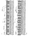
- the holes (3, 38) have apertures at least toward the first, underlying thermoplastic layer (8) and provided with a thermoplastic matrix (4, 48) compatible with the first thermoplastic matrix material (88) and provided with reinforcement fibres (5, 58). This basic cross-section is illustrated in Fig. 1 .
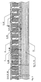
- a top, frontal FRTP layer (7) is comprised in a preferred embodiment. This is shown in Fig. 3 .
- the antiballistic armour plate according to the invention may have a laminate layer of a second, overlying fibre reinforced thermoplastic layer (7).
- the antiballistic armour plate so formed may be provided with one or more of the holes (3) provided with a thermoplastic matrix (4, 47) compatible with a thermoplastic matrix material of the second, overlying thermoplastic layer (7).
- the thermoplastic matrix (4, 47) is provided with reinforcement fibres (5, 57).
- the holes (3, 37) may be through holes or open toward the front of the ceramic.
- the holes (3) have a diameter less than about 3 mm which is a diameter of a penetrator spearhead of commonly used handheld projectiles for handheld guns.
- the present production process of the applicant is to vacuum bake fibre reinforced thermoplastic cloths to the front and the rear of the ceramic plate and usually behind the rearmost package of antiballistic cloths forming the spall liner.
- This is a highly efficient and durable encapsulation of antiballistic ceramic plates. It should be reasonable to believe that the new feature of matrix-filled and reinforced matrix filled holes through the laminated frtp - ceram - frtp will improve the antiballistic properties including anti-delamination effect and weight. This is particularly valid when a majority of the holes extend through the ceramic tiles, such as illustrated in Fig. 3 and in Fig. 7 .
- the material of the matrix in the holes should be chemically and mechanically compatible with the material of the thermoplastic matrix at the front and the rear of the ceramic plate. In a preferred embodiment it should be generally the same thermoplastic material, either pre-filled or plugged into the holes or formed by vacuum overflow from melted thermoplastic material during the vacuum baking process.
- a thread such as chine twist may be sewn through the holes in the plate.
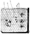
- Such a sewing process may be conducted during a dry layup phase before the vacuum baking process is conducted. If the ceramic plates have a regular and predictable pattern such as illustrated in Fig. 4 and in Fig. 5 it is feasible to conduct the sewing process automatically in an industrial sewing machine.
- this arrangement of holes may still reinforce the laminate efficiently while retaining a good weight reduction as compared to a ceramic without holes.
- Reinforcement fibres may be distributed in the matrix in the holes.
- the matrix which forms a continuum with the matrix of the front layer may form anchoring elements in the entire depth of the holes, and the cylindrical surface of the solid matrix forms a cylinder surface area in contact with the wall of the hole. The sum of all such cylinder / hole wall contact surfaces significantly increases the contact area of the front laminate. A significantly increased contact area generally increases the lamination strength and prevents delamination.
- a hole may stop or deviate a crack in the ceramic from propagating across the hole because the matrix of the hole may absorb energy without cracking.
- the crushing process may stop at the ceramic / matrix interface in the hole. From the above one will see that the matrix-filed holes both contribute to anchoring of the frontal frtp layer to the ceramic layer and thus prevents delamination. This is valid whether the holes are through or nearly through. This is further significantly improved since the matrix in the holes carries reinforcement fibres such as shown in Figs. 3 , 7 , and 8 .
- the matrix-filled holes counteract the propagation of cracks and crushing along the ceramic layer and thus reduce the vulnerability to multi-hits. Further, the matrix-filled holes significantly contribute to a ceramic weight reduction per area of the ceramic layer, which may be utilized in several ways, first as merely a weight reduction if weight is the main issue such as for personnel or light vehicles, or secondly utilized for increasing the thickness in order to further improve the antiballistic capacity of the shield, if weight is not the main issue, such as for heavily armoured vehicles.
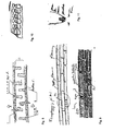
- Fig. 8 is illustrated a set of disruptive forces acting on the front and back frtp laminate layers away from the ceramic with reinforced matrix-filled holes.
- the disruptive forces will set up a tension force in each affected matrix cylinder anchoring the frtp layer to the hole wall.
- the disruptive forces will transfer as a shear force through the cylinder interface and at least partly propagate as a shear force to the opposite face as illustrated by the half-arrows in Fig. 8 .
- matrix-filled reinforced through holes such as in Fig. 3 while in such situations the tension force in the anchor matrix is also transferred directly through the matrix-filled holes.
- Fig. 9 illustrate roughly a cross-section of an frtp - ceramic - frtp laminate according to the invention in which the ceramic layer comprises three layers.
- the three (two or more) layers of ceramic may be subdivided into tiles.
- the tiles may be glued end on end in the desired pattern, and the tiles may be plane, kinked or curved depending on whether the shield as such is desired to be plane, curved, or be constituted by two or more planes having sharp or rounded transitions.
- One or more of the ceramic layers, whether continuous or tiled, are provided with holes.
- Thermoplastic matrix is arranged in the holes.
- the matrix fill may be fibre reinforced as for the embodiments above. Between the two or more layers of ceramic thermoplastic may be used.
- thermoplastic bonding layer may be constituted by a thin film or net or mat of thermoplastic so as forming a dry lay-up for being vacuum pumped and vacuum baked.
- the ceramic layers may be bonded by other adhesives such as epoxy glue.
- a thermoplastic binder may be less brittle than an epoxy glue.
- Fig. 11 roughly illustrates the front tip of a light handgun or machine gun ammunition projectile having a so-called penetrator spearhead for penetrating armour plates.
- the holes should have a diameter similar to or less than the diameter of such penetrator spearheads, e.g. 3 mm or less.
- Fig. 12 is an illustration of, in the upper part, a section of multilayer ceramic tiles of which the axis of the holes vary from one layer to another layer.
- a device one may attempt to progressively deviate a near perpendicular impact path away from the perpendicular line and approaching the plane of the ceramic layers so as for increasing the path to be penetrated and to attempt to turn the projectile facing sidewards into the shield.
- ceramic layers hole axes have discontinuous directions from one layer to the next, which may create discontinuities that may disturb the projectile's propagation through the ceramic layer.
- Fig. 13 illustrates an embodiment of the invention in which inward protruding or outward protruding rifles are formed along the wall of the holes in the ceramic.
- Such rifles whether protruding inwards or outwards from the wall will create ribs that increases the area of the generally cylindrical wall of the hole, and thus increases the binding between the ceramic plate and the matrix filling the hole, thus increasing the lamination strength of the frtp - ceram - frtp laminate.
- the increased area of the cylinder wall may stiffen off the wall locally.
- a rifled wall may also contribute to predefine break lines through the ceramic thus further delimiting crack or crushing propagation.
- the rifles are non-parallel to the axis of the hole.
- Fig. 14 illustrates a general lay-up of a shield to be formed according to the invention:
- Fig. 15 is illustrated an antiballistic armour plate according to the invention in which one or more of said underlying or frontal thermoplastic fibre reinforced layers (8, 7) is pre-formed with knobs (89) arranged for fitting into corresponding holes in one or more of said ceramic antiballistic plates (2).
Landscapes
- Engineering & Computer Science (AREA)
- Chemical & Material Sciences (AREA)
- Ceramic Engineering (AREA)
- General Engineering & Computer Science (AREA)
- Laminated Bodies (AREA)
- Aiming, Guidance, Guns With A Light Source, Armor, Camouflage, And Targets (AREA)
Claims (17)
- Plaque de blindage antibalistique comprenant- une ou plusieurs couches d'une ou plusieurs plaques en céramique antibalistiques (2) feuilletées avec une première couche de base thermoplastique renforcée en fibres (8) comprenant un premier matériau thermoplastique (88) et des fibres de renforcement (82), lesdites plaques en céramique antibalistiques (2) étant disposées pour recevoir et déformer des projectiles ou éclats balistiques, et doublée par- un revêtement écaillé (10) d'une ou plusieurs feuilles faiblement liées (11) de fibres antibalistiques (12) disposé pour recevoir les projectiles ou éclats balistiques ayant pénétrés lesdites plaques en céramique (2);- une ou plusieurs desdites plaques en céramique (2) pourvues de trous (3, 38) répartis sur lesdites une ou plusieurs plaques en céramique (2) lesdits trous ayant des ouvertures au moins en direction de ladite première couche thermoplastique de base (8) caractérisé en ce que- lesdits trous (3, 38) sont prévus avec une matrice thermoplastique (4, 48) compatible avec ledit premier matériau matriciel thermoplastique (88) et sont prévus avec des fibres de renforcement (5, 58).
- Plaque de blindage antibalistique selon la revendication 1, dans laquelle une face avant desdites une ou plusieurs plaques en céramique antibalistiques (2) est feuilletée avec une seconde couche avant thermoplastique renforcée en fibres (7).
- Plaque de blindage antibalistique selon la revendication 2, dans laquelle un ou plusieurs desdits trous (3) dans lesdites plaques en céramique (2) sont prévus avec une matrice thermoplastique (4, 47) compatible avec un matériau matriciel thermoplastique de ladite seconde couche thermoplastique recouvrante (7), ladite matrice thermoplastique (4, 47) étant prévue avec des fibres de renforcement (5, 57).
- Plaque de blindage antibalistique selon la revendication 1, dans laquelle lesdits trous (3) dans lesdites plaques en céramique (2) ont un diamètre inférieur à environ 3mm.
- Plaque de blindage antibalistique selon la revendication 1, dans laquelle lesdites fibres de renforcement (5, 58) comprennent des microfibres courtes ou des nanofibres telles que des fibres de carbone ou des trichites.
- Plaque de blindage antibalistique selon la revendication 1, dans laquelle plusieurs desdits trous (3) s'étendent à travers la plaque en céramique (2).
- Plaque de blindage antibalistique selon la revendication 1, dans laquelle au moins une partie desdites fibres de renforcement (5, 58) sont ancrées dans ladite couche thermoplastique de base (8, 78).
- Plaque de blindage antibalistique selon les revendications 6 et 7, dans laquelle au moins une partie des fibres de renforcement (82, 58) dans lesdits trous (3) desdites couches thermoplastiques renforcée en fibres de base et / ou frontales (8, 7) est enfilée dans les deux sens à travers lesdits trous (3).
- Plaque de blindage antibalistique selon la revendication 1, dans laquelle une ou plusieurs desdites couches thermoplastiques renforcées en fibres de base ou frontales (8, 7) est préformée avec des bossages (89) disposés pour s'engager dans les trous correspondant dans une ou plusieurs desdites plaques en céramique antibalistiques (2).
- Plaque de blindage antibalistique selon la revendication 1, dans laquelle des axes desdits trous (3) s'écartent selon une direction perpendiculaire par rapport à la surface frontale de ladite couche céramique (2).
- Plaque de blindage antibalistique selon la revendication 1, dans laquelle l'une ou lesdites plusieurs couches d'une ou plusieurs plaques en céramique antibalistiques (2) est subdivisée en carreaux de céramique.
- Plaque de blindage antibalistique selon la revendication 4, dans laquelle lesdits trous (3) dans lesdites plaques en céramique (2) ont un diamètre compris entre 0.1mm et 3mm.
- Méthode pour former une plaque de blindage antibalistique, comprenant :- l'application d'au moins une ou plusieurs secondes couches de tissus thermoplastiques renforcées en fibres sèches (7) dans un moule pour former une couche frontale de ladite plaque de blindage,- la disposition d'une ou plusieurs plaques en céramique antibalistiques (2) sur lesdites secondes couches de tissus thermoplastiques renforcées en fibres (7), lesdites plaques en céramique ayant des trous (3) répartis uniformément sur la surface de ladite plaque en céramique (2),- l'application d'au moins une ou plusieurs premières couches de tissus thermoplastiques renforcées en fibres sèches (8) comprenant un premier matériau thermoplastique (88) sur lesdites une ou plusieurs couches de plaques en céramique (2).- la fourniture d'une matrice thermoplastique (4, 48) compatible avec ledit premier matériau matriciel thermoplastique (88) desdites premières couches et prévue avec les fibres de renforcement (5, 58) pour lesdits trous (3).- l'application d'un ou plusieurs revêtements écaillés (10) formant des couches antibalistiques de fibres telles que des fibres en aramide, alternant avec des films de liaisons faibles sur ladite première couche de tissus renforcée en fibres thermoplastiques (8),- le pompage par le vide de la superposition de couches formées ci-dessus,- le chauffage de ladite superposition de couches formée jusqu'à un degré de fusion souhaité de la partie thermoplastique desdits premier ou second tissus renforcés en fibres (8, 7) constitué de tout ou partie de ladite matrice thermoplastique (4) dans lesdits trous (3) desdites plaques céramiques (2),- le refroidissement de ladite superposition de couches étuvées sous vide jusqu'à ce que ladite matrice thermoplastique en fusion (88, 4, 48) fixe et accroche ladite superposition de couches renforcées en fibres pour former ladite plaque de blindage antibalistique.
- Méthode selon la revendication 13, comprenant l'étape consistant dans, l'application du revêtement écaillé formant les couches antibalistiques (10), fournir une troisième couche d'un ou plusieurs tissus thermoplastiques renforcés en fibres sèches (13) pour former une couche enveloppante arrière derrière ledit revêtement écaillé (10).
- Méthode selon la revendication 13, dans laquelle ladite matrice thermoplastique (48) desdits trous est globalement continue avec la matrice thermoplastique (88) de ladite première couche thermoplastique (8) renforcée en fibres.
- Méthode selon la revendication 3, dans laquelle ledit renforcement en fibres (5, 58) dans lesdits trous (4) est obtenu par enfilage, couture ou tricotage de ladite fibre renforcée (8) à ladite une ou plusieurs plaques en céramiques (2) utilisant lesdits trous (3).
- Méthode selon la revendication 13, dans laquelle ledit renforcement en fibres (5, 58) dans lesdits trous (3) forme une partie continue desdites fibres de renforcement desdites première et / ou seconde couches de tissus thermoplastiques renforcées en fibres (8, 7).
Applications Claiming Priority (2)
| Application Number | Priority Date | Filing Date | Title |
|---|---|---|---|
| US22391609P | 2009-07-08 | 2009-07-08 | |
| PCT/NO2010/000263 WO2011005109A1 (fr) | 2009-07-08 | 2010-07-02 | Plaque de blindage antibalistique et procédé de fabrication de cette plaque antibalistique |
Publications (2)
| Publication Number | Publication Date |
|---|---|
| EP2452154A1 EP2452154A1 (fr) | 2012-05-16 |
| EP2452154B1 true EP2452154B1 (fr) | 2013-01-09 |
Family
ID=41022402
Family Applications (1)
| Application Number | Title | Priority Date | Filing Date |
|---|---|---|---|
| EP10749925A Not-in-force EP2452154B1 (fr) | 2009-07-08 | 2010-07-02 | Plaque de blindage antibalistique et procédé de fabrication de cette plaque antibalistique |
Country Status (4)
| Country | Link |
|---|---|
| US (1) | US20120192705A1 (fr) |
| EP (1) | EP2452154B1 (fr) |
| GB (1) | GB2471702B (fr) |
| WO (1) | WO2011005109A1 (fr) |
Families Citing this family (6)
| Publication number | Priority date | Publication date | Assignee | Title |
|---|---|---|---|---|
| GB2504497B (en) | 2012-07-27 | 2014-07-30 | Np Aerospace Ltd | Armour |
| FR3092659B1 (fr) * | 2019-02-13 | 2022-06-17 | Protecop | Vêtement de protection, par exemple gilet pare-balles, porte-plaque ou analogue |
| IL272508B (en) * | 2020-02-06 | 2021-09-30 | Plasan Sasa Ltd | Protection systems with a perforated layer |
| CN112179212A (zh) * | 2020-08-24 | 2021-01-05 | 西安交通大学 | 一种异型孔结构防护装甲 |
| CN112571302A (zh) * | 2020-12-28 | 2021-03-30 | 株洲飞马橡胶实业有限公司 | 一种高耐磨板及其制备方法和在抛丸机设备中的应用 |
| IT202400000597A1 (it) | 2024-01-15 | 2025-07-15 | Salvatore COGONI | Barriera di protezione |
Family Cites Families (7)
| Publication number | Priority date | Publication date | Assignee | Title |
|---|---|---|---|---|
| DE19834393A1 (de) * | 1998-07-30 | 2000-02-03 | Etec Ges Fuer Tech Keramik Mbh | Plattenelement für eine Schutzeinrichtung |
| GB2364956A (en) * | 2000-07-28 | 2002-02-13 | David Adie | Ballistic protection shield |
| EP1499847A2 (fr) * | 2002-04-17 | 2005-01-26 | Armor Systems International | Systeme de blindage |
| US20060213360A1 (en) * | 2005-03-23 | 2006-09-28 | Mosche Ravid | Perforated armor plates |
| NO327530B1 (no) * | 2007-06-07 | 2009-08-03 | Frec Technology As | En vakuumbag-rammesammenstilling for bruk ved fremstilling av fiberarmerte komposittpaneler |
| US8006605B2 (en) * | 2007-10-10 | 2011-08-30 | Hardware, LLC | Armor panel system |
| US20110168003A1 (en) * | 2009-04-14 | 2011-07-14 | Young-Hwa Kim | Armor assembly including multiple armor plates |
-
2009
- 2009-07-09 GB GB0911936.3A patent/GB2471702B/en not_active Expired - Fee Related
-
2010
- 2010-07-02 WO PCT/NO2010/000263 patent/WO2011005109A1/fr not_active Ceased
- 2010-07-02 EP EP10749925A patent/EP2452154B1/fr not_active Not-in-force
- 2010-07-07 US US12/831,727 patent/US20120192705A1/en not_active Abandoned
Also Published As
| Publication number | Publication date |
|---|---|
| GB0911936D0 (en) | 2009-08-19 |
| WO2011005109A9 (fr) | 2011-07-07 |
| WO2011005109A1 (fr) | 2011-01-13 |
| US20120192705A1 (en) | 2012-08-02 |
| EP2452154A1 (fr) | 2012-05-16 |
| GB2471702A (en) | 2011-01-12 |
| GB2471702B (en) | 2013-05-08 |
Similar Documents
| Publication | Publication Date | Title |
|---|---|---|
| US5970843A (en) | Fiber reinforced ceramic matrix composite armor | |
| US20120192705A1 (en) | Antiballistic armour plate and a method for manufacturing such an antiballistic armour plate | |
| US7866248B2 (en) | Encapsulated ceramic composite armor | |
| US5440965A (en) | Armor systems | |
| US6276254B1 (en) | Armor systems | |
| EP2008051B1 (fr) | Système de blindage anti-projectiles léger présentant une amélioration de surface | |
| CN205138327U (zh) | 一种复合结构防弹板 | |
| Medvedovski | Lightweight ceramic composite armour system | |
| CN105444622A (zh) | 一种复合结构防弹板及其制造方法 | |
| WO2009080311A1 (fr) | Blindage de protection | |
| EP0500795A1 (fr) | Blindage composite anti-balistique | |
| CN111805983A (zh) | 一种防弹单元及其制造工艺 | |
| EP2877808B1 (fr) | Blindage | |
| Rahbek et al. | Improved ballistic limit velocity from filament-wound fibres as composite cover on ceramic tiles | |
| He et al. | Designing SiC ceramic composite armor structure to resist multiple impacts from armor-piercing incendiary bullets | |
| EP0558693A1 (fr) | Blindage composite de resistance balistique | |
| WO1991007633A1 (fr) | Blindage composite anti-balistique a resistance amelioree a des coups multiples | |
| CN116518780A (zh) | 一种抗14.5mm穿甲弹的功能梯度装甲结构 | |
| RU2393416C1 (ru) | Многослойная бронепреграда | |
| WO2008097375A2 (fr) | Blindage composite céramique encapsulé | |
| CN217110674U (zh) | 一种抗穿甲燃烧弹侵彻的复合装甲板 | |
| RU193794U1 (ru) | Композитная пулезащитная бронепанель для бронежилета | |
| JP5405844B2 (ja) | 耐衝撃部材 | |
| CA3150510C (fr) | Panneau antibalistique concu pour une inspection optique et procede associe | |
| EP3140194B1 (fr) | Réservoir ou récipient destiné à contenir un fluide |
Legal Events
| Date | Code | Title | Description |
|---|---|---|---|
| PUAI | Public reference made under article 153(3) epc to a published international application that has entered the european phase |
Free format text: ORIGINAL CODE: 0009012 |
|
| 17P | Request for examination filed |
Effective date: 20120208 |
|
| AK | Designated contracting states |
Kind code of ref document: A1 Designated state(s): AL AT BE BG CH CY CZ DE DK EE ES FI FR GR HR HU IE IS IT LI LT LU LV MC MK MT NL NO PL PT RO SE SI SK SM TR |
|
| GRAP | Despatch of communication of intention to grant a patent |
Free format text: ORIGINAL CODE: EPIDOSNIGR1 |
|
| DAX | Request for extension of the european patent (deleted) | ||
| GRAS | Grant fee paid |
Free format text: ORIGINAL CODE: EPIDOSNIGR3 |
|
| GRAA | (expected) grant |
Free format text: ORIGINAL CODE: 0009210 |
|
| AK | Designated contracting states |
Kind code of ref document: B1 Designated state(s): AL AT BE BG CH CY CZ DE DK EE ES FI FR GR HR HU IE IS IT LI LT LU LV MC MK MT NL NO PL PT RO SE SI SK SM TR |
|
| REG | Reference to a national code |
Ref country code: AT Ref legal event code: REF Ref document number: 592991 Country of ref document: AT Kind code of ref document: T Effective date: 20130115 Ref country code: CH Ref legal event code: EP |
|
| REG | Reference to a national code |
Ref country code: IE Ref legal event code: FG4D |
|
| REG | Reference to a national code |
Ref country code: DE Ref legal event code: R096 Ref document number: 602010004560 Country of ref document: DE Effective date: 20130307 |
|
| PG25 | Lapsed in a contracting state [announced via postgrant information from national office to epo] |
Ref country code: SI Free format text: LAPSE BECAUSE OF FAILURE TO SUBMIT A TRANSLATION OF THE DESCRIPTION OR TO PAY THE FEE WITHIN THE PRESCRIBED TIME-LIMIT Effective date: 20130109 |
|
| REG | Reference to a national code |
Ref country code: NL Ref legal event code: VDEP Effective date: 20130109 |
|
| REG | Reference to a national code |
Ref country code: AT Ref legal event code: MK05 Ref document number: 592991 Country of ref document: AT Kind code of ref document: T Effective date: 20130109 |
|
| REG | Reference to a national code |
Ref country code: LT Ref legal event code: MG4D |
|
| PG25 | Lapsed in a contracting state [announced via postgrant information from national office to epo] |
Ref country code: AT Free format text: LAPSE BECAUSE OF FAILURE TO SUBMIT A TRANSLATION OF THE DESCRIPTION OR TO PAY THE FEE WITHIN THE PRESCRIBED TIME-LIMIT Effective date: 20130109 Ref country code: BE Free format text: LAPSE BECAUSE OF FAILURE TO SUBMIT A TRANSLATION OF THE DESCRIPTION OR TO PAY THE FEE WITHIN THE PRESCRIBED TIME-LIMIT Effective date: 20130109 Ref country code: LT Free format text: LAPSE BECAUSE OF FAILURE TO SUBMIT A TRANSLATION OF THE DESCRIPTION OR TO PAY THE FEE WITHIN THE PRESCRIBED TIME-LIMIT Effective date: 20130109 Ref country code: IS Free format text: LAPSE BECAUSE OF FAILURE TO SUBMIT A TRANSLATION OF THE DESCRIPTION OR TO PAY THE FEE WITHIN THE PRESCRIBED TIME-LIMIT Effective date: 20130509 Ref country code: SE Free format text: LAPSE BECAUSE OF FAILURE TO SUBMIT A TRANSLATION OF THE DESCRIPTION OR TO PAY THE FEE WITHIN THE PRESCRIBED TIME-LIMIT Effective date: 20130109 Ref country code: BG Free format text: LAPSE BECAUSE OF FAILURE TO SUBMIT A TRANSLATION OF THE DESCRIPTION OR TO PAY THE FEE WITHIN THE PRESCRIBED TIME-LIMIT Effective date: 20130409 Ref country code: ES Free format text: LAPSE BECAUSE OF FAILURE TO SUBMIT A TRANSLATION OF THE DESCRIPTION OR TO PAY THE FEE WITHIN THE PRESCRIBED TIME-LIMIT Effective date: 20130420 Ref country code: NO Free format text: LAPSE BECAUSE OF FAILURE TO SUBMIT A TRANSLATION OF THE DESCRIPTION OR TO PAY THE FEE WITHIN THE PRESCRIBED TIME-LIMIT Effective date: 20130409 |
|
| PG25 | Lapsed in a contracting state [announced via postgrant information from national office to epo] |
Ref country code: PL Free format text: LAPSE BECAUSE OF FAILURE TO SUBMIT A TRANSLATION OF THE DESCRIPTION OR TO PAY THE FEE WITHIN THE PRESCRIBED TIME-LIMIT Effective date: 20130109 Ref country code: LV Free format text: LAPSE BECAUSE OF FAILURE TO SUBMIT A TRANSLATION OF THE DESCRIPTION OR TO PAY THE FEE WITHIN THE PRESCRIBED TIME-LIMIT Effective date: 20130109 Ref country code: GR Free format text: LAPSE BECAUSE OF FAILURE TO SUBMIT A TRANSLATION OF THE DESCRIPTION OR TO PAY THE FEE WITHIN THE PRESCRIBED TIME-LIMIT Effective date: 20130410 Ref country code: NL Free format text: LAPSE BECAUSE OF FAILURE TO SUBMIT A TRANSLATION OF THE DESCRIPTION OR TO PAY THE FEE WITHIN THE PRESCRIBED TIME-LIMIT Effective date: 20130109 Ref country code: FI Free format text: LAPSE BECAUSE OF FAILURE TO SUBMIT A TRANSLATION OF THE DESCRIPTION OR TO PAY THE FEE WITHIN THE PRESCRIBED TIME-LIMIT Effective date: 20130109 Ref country code: PT Free format text: LAPSE BECAUSE OF FAILURE TO SUBMIT A TRANSLATION OF THE DESCRIPTION OR TO PAY THE FEE WITHIN THE PRESCRIBED TIME-LIMIT Effective date: 20130509 |
|
| PG25 | Lapsed in a contracting state [announced via postgrant information from national office to epo] |
Ref country code: HR Free format text: LAPSE BECAUSE OF FAILURE TO SUBMIT A TRANSLATION OF THE DESCRIPTION OR TO PAY THE FEE WITHIN THE PRESCRIBED TIME-LIMIT Effective date: 20130109 |
|
| PG25 | Lapsed in a contracting state [announced via postgrant information from national office to epo] |
Ref country code: SK Free format text: LAPSE BECAUSE OF FAILURE TO SUBMIT A TRANSLATION OF THE DESCRIPTION OR TO PAY THE FEE WITHIN THE PRESCRIBED TIME-LIMIT Effective date: 20130109 Ref country code: RO Free format text: LAPSE BECAUSE OF FAILURE TO SUBMIT A TRANSLATION OF THE DESCRIPTION OR TO PAY THE FEE WITHIN THE PRESCRIBED TIME-LIMIT Effective date: 20130109 Ref country code: DK Free format text: LAPSE BECAUSE OF FAILURE TO SUBMIT A TRANSLATION OF THE DESCRIPTION OR TO PAY THE FEE WITHIN THE PRESCRIBED TIME-LIMIT Effective date: 20130109 Ref country code: CZ Free format text: LAPSE BECAUSE OF FAILURE TO SUBMIT A TRANSLATION OF THE DESCRIPTION OR TO PAY THE FEE WITHIN THE PRESCRIBED TIME-LIMIT Effective date: 20130109 Ref country code: EE Free format text: LAPSE BECAUSE OF FAILURE TO SUBMIT A TRANSLATION OF THE DESCRIPTION OR TO PAY THE FEE WITHIN THE PRESCRIBED TIME-LIMIT Effective date: 20130109 |
|
| PLBE | No opposition filed within time limit |
Free format text: ORIGINAL CODE: 0009261 |
|
| STAA | Information on the status of an ep patent application or granted ep patent |
Free format text: STATUS: NO OPPOSITION FILED WITHIN TIME LIMIT |
|
| PG25 | Lapsed in a contracting state [announced via postgrant information from national office to epo] |
Ref country code: CY Free format text: LAPSE BECAUSE OF FAILURE TO SUBMIT A TRANSLATION OF THE DESCRIPTION OR TO PAY THE FEE WITHIN THE PRESCRIBED TIME-LIMIT Effective date: 20130109 |
|
| 26N | No opposition filed |
Effective date: 20131010 |
|
| REG | Reference to a national code |
Ref country code: DE Ref legal event code: R097 Ref document number: 602010004560 Country of ref document: DE Effective date: 20131010 |
|
| PG25 | Lapsed in a contracting state [announced via postgrant information from national office to epo] |
Ref country code: MC Free format text: LAPSE BECAUSE OF FAILURE TO SUBMIT A TRANSLATION OF THE DESCRIPTION OR TO PAY THE FEE WITHIN THE PRESCRIBED TIME-LIMIT Effective date: 20130109 |
|
| REG | Reference to a national code |
Ref country code: IE Ref legal event code: MM4A |
|
| PG25 | Lapsed in a contracting state [announced via postgrant information from national office to epo] |
Ref country code: IE Free format text: LAPSE BECAUSE OF NON-PAYMENT OF DUE FEES Effective date: 20130702 |
|
| REG | Reference to a national code |
Ref country code: CH Ref legal event code: PL |
|
| PG25 | Lapsed in a contracting state [announced via postgrant information from national office to epo] |
Ref country code: CH Free format text: LAPSE BECAUSE OF NON-PAYMENT OF DUE FEES Effective date: 20140731 Ref country code: LI Free format text: LAPSE BECAUSE OF NON-PAYMENT OF DUE FEES Effective date: 20140731 |
|
| PG25 | Lapsed in a contracting state [announced via postgrant information from national office to epo] |
Ref country code: SM Free format text: LAPSE BECAUSE OF FAILURE TO SUBMIT A TRANSLATION OF THE DESCRIPTION OR TO PAY THE FEE WITHIN THE PRESCRIBED TIME-LIMIT Effective date: 20130109 |
|
| PG25 | Lapsed in a contracting state [announced via postgrant information from national office to epo] |
Ref country code: TR Free format text: LAPSE BECAUSE OF FAILURE TO SUBMIT A TRANSLATION OF THE DESCRIPTION OR TO PAY THE FEE WITHIN THE PRESCRIBED TIME-LIMIT Effective date: 20130109 Ref country code: MT Free format text: LAPSE BECAUSE OF FAILURE TO SUBMIT A TRANSLATION OF THE DESCRIPTION OR TO PAY THE FEE WITHIN THE PRESCRIBED TIME-LIMIT Effective date: 20130109 |
|
| PG25 | Lapsed in a contracting state [announced via postgrant information from national office to epo] |
Ref country code: LU Free format text: LAPSE BECAUSE OF NON-PAYMENT OF DUE FEES Effective date: 20130702 Ref country code: HU Free format text: LAPSE BECAUSE OF FAILURE TO SUBMIT A TRANSLATION OF THE DESCRIPTION OR TO PAY THE FEE WITHIN THE PRESCRIBED TIME-LIMIT; INVALID AB INITIO Effective date: 20100702 Ref country code: MK Free format text: LAPSE BECAUSE OF FAILURE TO SUBMIT A TRANSLATION OF THE DESCRIPTION OR TO PAY THE FEE WITHIN THE PRESCRIBED TIME-LIMIT Effective date: 20130109 |
|
| REG | Reference to a national code |
Ref country code: FR Ref legal event code: PLFP Year of fee payment: 7 |
|
| PGFP | Annual fee paid to national office [announced via postgrant information from national office to epo] |
Ref country code: IT Payment date: 20160615 Year of fee payment: 7 |
|
| PGFP | Annual fee paid to national office [announced via postgrant information from national office to epo] |
Ref country code: DE Payment date: 20160923 Year of fee payment: 7 |
|
| PGFP | Annual fee paid to national office [announced via postgrant information from national office to epo] |
Ref country code: FR Payment date: 20160718 Year of fee payment: 7 |
|
| REG | Reference to a national code |
Ref country code: DE Ref legal event code: R119 Ref document number: 602010004560 Country of ref document: DE |
|
| REG | Reference to a national code |
Ref country code: FR Ref legal event code: ST Effective date: 20180330 |
|
| PG25 | Lapsed in a contracting state [announced via postgrant information from national office to epo] |
Ref country code: DE Free format text: LAPSE BECAUSE OF NON-PAYMENT OF DUE FEES Effective date: 20180201 |
|
| PG25 | Lapsed in a contracting state [announced via postgrant information from national office to epo] |
Ref country code: FR Free format text: LAPSE BECAUSE OF NON-PAYMENT OF DUE FEES Effective date: 20170731 |
|
| PG25 | Lapsed in a contracting state [announced via postgrant information from national office to epo] |
Ref country code: IT Free format text: LAPSE BECAUSE OF NON-PAYMENT OF DUE FEES Effective date: 20170702 |
|
| PG25 | Lapsed in a contracting state [announced via postgrant information from national office to epo] |
Ref country code: AL Free format text: LAPSE BECAUSE OF FAILURE TO SUBMIT A TRANSLATION OF THE DESCRIPTION OR TO PAY THE FEE WITHIN THE PRESCRIBED TIME-LIMIT Effective date: 20130109 |