EP2451526B2 - An improved external charger for a medical implantable device using field sensing coils to improve coupling - Google Patents
An improved external charger for a medical implantable device using field sensing coils to improve coupling Download PDFInfo
- Publication number
- EP2451526B2 EP2451526B2 EP10731691.1A EP10731691A EP2451526B2 EP 2451526 B2 EP2451526 B2 EP 2451526B2 EP 10731691 A EP10731691 A EP 10731691A EP 2451526 B2 EP2451526 B2 EP 2451526B2
- Authority
- EP
- European Patent Office
- Prior art keywords
- external charger
- coils
- sensing
- sensing coils
- primary coil
- Prior art date
- Legal status (The legal status is an assumption and is not a legal conclusion. Google has not performed a legal analysis and makes no representation as to the accuracy of the status listed.)
- Active
Links
Images


Classifications
-
- G—PHYSICS
- G01—MEASURING; TESTING
- G01B—MEASURING LENGTH, THICKNESS OR SIMILAR LINEAR DIMENSIONS; MEASURING ANGLES; MEASURING AREAS; MEASURING IRREGULARITIES OF SURFACES OR CONTOURS
- G01B7/00—Measuring arrangements characterised by the use of electric or magnetic techniques
- G01B7/14—Measuring arrangements characterised by the use of electric or magnetic techniques for measuring distance or clearance between spaced objects or spaced apertures
-
- A—HUMAN NECESSITIES
- A61—MEDICAL OR VETERINARY SCIENCE; HYGIENE
- A61N—ELECTROTHERAPY; MAGNETOTHERAPY; RADIATION THERAPY; ULTRASOUND THERAPY
- A61N1/00—Electrotherapy; Circuits therefor
- A61N1/18—Applying electric currents by contact electrodes
- A61N1/32—Applying electric currents by contact electrodes alternating or intermittent currents
- A61N1/36—Applying electric currents by contact electrodes alternating or intermittent currents for stimulation
- A61N1/372—Arrangements in connection with the implantation of stimulators
- A61N1/378—Electrical supply
- A61N1/3787—Electrical supply from an external energy source
-
- H—ELECTRICITY
- H02—GENERATION; CONVERSION OR DISTRIBUTION OF ELECTRIC POWER
- H02J—ELECTRIC POWER NETWORKS; CIRCUIT ARRANGEMENTS OR SYSTEMS FOR SUPPLYING OR DISTRIBUTING ELECTRIC POWER; SYSTEMS FOR STORING ELECTRIC ENERGY
- H02J50/00—Circuit arrangements or systems for wireless supply or distribution of electric power
- H02J50/10—Circuit arrangements or systems for wireless supply or distribution of electric power using inductive coupling
-
- H—ELECTRICITY
- H02—GENERATION; CONVERSION OR DISTRIBUTION OF ELECTRIC POWER
- H02J—ELECTRIC POWER NETWORKS; CIRCUIT ARRANGEMENTS OR SYSTEMS FOR SUPPLYING OR DISTRIBUTING ELECTRIC POWER; SYSTEMS FOR STORING ELECTRIC ENERGY
- H02J50/00—Circuit arrangements or systems for wireless supply or distribution of electric power
- H02J50/90—Circuit arrangements or systems for wireless supply or distribution of electric power involving detection or optimisation of position, e.g. alignment
-
- H—ELECTRICITY
- H02—GENERATION; CONVERSION OR DISTRIBUTION OF ELECTRIC POWER
- H02J—ELECTRIC POWER NETWORKS; CIRCUIT ARRANGEMENTS OR SYSTEMS FOR SUPPLYING OR DISTRIBUTING ELECTRIC POWER; SYSTEMS FOR STORING ELECTRIC ENERGY
- H02J7/00—Circuit arrangements for charging or discharging batteries or for supplying loads from batteries
- H02J7/70—Circuit arrangements for charging or discharging batteries or for supplying loads from batteries characterised by the mechanical construction
- H02J7/751—Circuit arrangements for charging or discharging batteries or for supplying loads from batteries characterised by the mechanical construction concerning the insertion or the connection of the batteries
-
- H—ELECTRICITY
- H01—ELECTRIC ELEMENTS
- H01F—MAGNETS; INDUCTANCES; TRANSFORMERS; SELECTION OF MATERIALS FOR THEIR MAGNETIC PROPERTIES
- H01F38/00—Adaptations of transformers or inductances for specific applications or functions
- H01F38/14—Inductive couplings
-
- H—ELECTRICITY
- H02—GENERATION; CONVERSION OR DISTRIBUTION OF ELECTRIC POWER
- H02J—ELECTRIC POWER NETWORKS; CIRCUIT ARRANGEMENTS OR SYSTEMS FOR SUPPLYING OR DISTRIBUTING ELECTRIC POWER; SYSTEMS FOR STORING ELECTRIC ENERGY
- H02J2105/00—Networks for supplying or distributing electric power characterised by their spatial reach or by the load
- H02J2105/40—Networks for supplying or distributing electric power characterised by their spatial reach or by the load characterised by the loads connecting to the networks or being supplied by the networks
- H02J2105/46—Medical devices, medical implants or life supporting devices
Definitions
- the present invention relates to techniques for providing improved alignment between an external charger and an implantable device.
- Implantable stimulation devices generate and deliver electrical stimuli to body nerves and tissues for the therapy of various biological disorders, such as pacemakers to treat cardiac arrhythmia, defibrillators to treat cardiac fibrillation, cochlear stimulators to treat deafness, retinal stimulators to treat blindness, muscle stimulators to produce coordinated limb movement, spinal cord stimulators to treat chronic pain, cortical and deep brain stimulators to treat motor and psychological disorders, and other neural stimulators to treat urinary incontinence, sleep apnea, shoulder sublaxation, etc.
- the present invention may find applicability in all such applications, although the description that follows will generally focus on the use of the invention within a Spinal Cord Stimulation (SCS) system, such as that disclosed in U.S. Patent Application 11/177,503, filed July 8, 2005 .
- SCS Spinal Cord Stimulation
- An SCS system typically includes an Implantable Pulse Generator (IPG), electrodes, at least one electrode lead, and, optionally, at least one electrode lead extension.
- IPG Implantable Pulse Generator
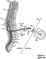
- the electrodes 106 which reside on a distal end of the electrode lead 102, are typically implanted along the dura 70 of the spinal cord 19, and the IPG 100 generates electrical pulses that are delivered through the electrodes 106 to the nerve fibers within the spinal column 19.
- Electrodes 106 are arranged in a desired pattern and spacing to create an electrode array 110. Individual wires 112 within one or more electrode leads 102 connect with each electrode 106 in the array 110.
- the electrode lead(s) 102 exit the spinal column 19 and may attach to one or more electrode lead extensions 120.
- the electrode lead extensions 120 are typically tunneled around the torso of the patient to a subcutaneous pocket where the IPG 100 is implanted.
- the electrode lead 102 may directly connect with the IPG 100.
- an IPG needs electrical power to function.
- Such power can be provided in several different ways, such as through the use of a rechargeable or non-rechargeable battery or through electromagnetic (EM) induction provided from an external charger, or from combinations of these and other approaches, which are discussed in further detail in U.S. Patent 6,553,263 ("the '263 patent").
- EM electromagnetic
- a rechargeable battery in the IPG such as a lithium-ion battery or a lithium-ion polymer battery.
- Such a rechargeable battery can generally supply sufficient power to run an IPG for a sufficient period (e.g., a day or more) between recharging.
- Recharging can occur through the use of EM induction, in which EM fields are sent by an external charger to the IPG.
- the patient in which the IPG is implanted can activate the external charger to transcutaneously (i.e., through the patient's flesh) charge the battery (e.g., at night when the patient is sleeping or during other convenient periods).
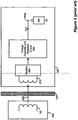
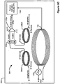
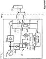
- the system comprises, in relevant part, the external charger 208 and IPG 100.
- a primary coil 130 in the charger 208 produces an EM field 290 capable of transcutaneous transmission through a patient's flesh 278.
- the external charger 208 may be powered by any known means, such as via a battery or by plugging into a wall outlet, for example.
- the EM field 290 is met at the IPG 100 by another coil 270, and accordingly, an AC voltage is induced in that coil 270. This AC voltage in turn is rectified to a DC voltage at a rectifier 682, which may comprise a standard bridge circuit.
- the rectified DC voltage is, in turn, sent to a charge controller and protection circuit 684, which operates generally to regulate the DC voltage and to produce either a constant voltage or constant current output as necessary for recharging the battery 180.
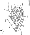
- Figure 3 shows further details of external charger 208 with the top portion of the housing removed. Further details concerning external chargers can be found in U.S. Patent Application 11/460,955, filed July 28, 2006 .
- electrical current 114 flowing in a counterclockwise direction through the primary coil 130 induces a magnetic field 290 having a prominent portion in a direction perpendicular to the plane in which the primary coil 130 lies.
- Primary coil 130 is typically formed of many turns of copper Litz wire, but the individual turns are not shown in Figure 3 for clarity.
- the magnetic field generated by the primary coil 130 induces an electrical current within a corresponding coil to charge a battery within, or otherwise provide power, to the IPG 100.
- This system is akin to a transformer where the primary coil is in the external charger 208 and secondary coil in the IPG 100.
- the efficiency of this coupling is largely dependent upon the alignment between the two coils, which efficiency can be expressed as a coupling factor, k.
- Achieving a good coupling factor is essential for optimizing efficiency of the inductive link. Not only does good coupling increase the power transferred to the implant, it minimizes heating in the implant, and also reduces the power requirements of the external charger, which reduces heating of the charger and allows a smaller form factor.
- Proper coupling is also essential if there is to be any data telemetry between the external charger 208 and the implant.
- Operation of the external charger 208 in the prior art typically involves the use of audio feedback to the user.
- the external charger 208 produces induced field 290 and begins searching for the IPG 100, as will be explained in more detail herein.
- An audio transducer in the external charger 208 would provide an intermittent audible sound (e.g., beeping) when coupling was poor between the charger 208 and the IPG 100, which beeping would alert the user to move the external charger relative to the IPG.
- the charger 208 would stop beeping, and the location of the charger 208 would be held in place over the IPG 100 by using double-side adhesive pads or a belt.
- the audio transducer would again start beeping, so that the position of the charger 208 relative to the IPG 100 could again be readjusted.
- a back-telemetry link from the IPG 100 would communicate to the charger 208 when the IPG battery was fully charged, which condition can again be audibly signaled to the patient.
- implantable devices would benefit from techniques for achieving improved coupling between an external charger and an implantable device that provide: the ability to accurately indicate the relative position of the charger to the implant; increased charging efficiency; faster charging rates; increased patient safety and comfort; lower power requirements; and a smaller form factor.
- This disclosure presents such a solution.
- FIG 1 shows an implantable pulse generator (IPG), an external charger, and the manner in which an electrode array is coupled to the IPG, in accordance with the prior art.
- IPG implantable pulse generator
- Figure 2 illustrates a prior art system comprising an external charger for charging an implantable pulse generator, including the charge controller and battery protection aspects of the IPG.
- Figure 3 shows a perspective view of a prior art external charger for an implantable medical device.
- Figures 4A-4C illustrate typical configurations, wherein the primary coil of a prior art external charging device is located at or near the outer surface of the patient's skin and the secondary coil of an implantable medical device is located near to or far from the inner surface of the patient's skin.
- Figure 5A shows a perspective view of one possible embodiment of an improved external charger for an implantable medical device.
- Figure 5B shows a typical configuration, wherein the primary coil of an improved external charging device is located at or near the outer surface of the patient's skin and the secondary coil of an implantable medical device is located near the inner surface of the patient's skin.
- Figure 5C shows two sensing coils whose outputs are sent to an instrumentation amplifier.
- Figure 5D shows a block diagram of circuitry for a system comprising an improved external charger for an implantable medical device.
- Figure 5E shows two sensing coils connected in series and end-to-end.
- Figure 5F shows a block diagram of circuitry for a system comprising an improved external charger for an implantable medical device.
- Figures 5G-5H illustrate typical configurations, wherein the primary coil of an improved external charging device is located at or near the outer surface of the patient's skin and the secondary coil of an implantable medical device is located near to or far from the inner surface of the patient's skin.
- Figure 6A shows a perspective view of another embodiment of an improved external charger for an implantable medical device.
- Figure 6B shows a circuit diagram for a system comprising an improved external charger for an implantable medical device.
- Figure 6C shows a top down view of a system comprising an improved external charger for an implantable medical device.
- Figure 7 shows a perspective view of one possible embodiment of an improved external charger for an implantable medical device.
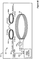
- Figure 8 shows a system comprising an improved external charger for charging an implantable pulse generator, including the alignment sensing and position indication circuitry of the external charger.
- Figure 9 is a flowchart detailing a technique for assuring the proper alignment of an external charger to an IPG.
- Figure 10 shows an improved external charger for charging an implantable pulse generator.
- the description that follows relates to use of the invention within a spinal cord stimulation (SCS) system.
- SCS spinal cord stimulation
- the invention is not so limited. Rather, the invention may be used with any type of implantable medical device that could benefit from improved alignment between an external charger and the implantable device.
- the present invention may be used as part of a system employing an external charger configured to charge a pacemaker, an implantable pump, a defibrillator, a cochlear stimulator, a retinal stimulator, a stimulator configured to produce coordinated limb movement, a cortical or deep brain stimulator, or in any other stimulator configured to treat urinary incontinence, sleep apnea, shoulder sublaxation, etc.
- the technique can be used in non-medical and/or non-implantable devices or systems as well, i.e., in any device or system in which proper coupling between a primary and second device is necessary or desirable.
- the present invention provides an improved external charger having improved means for determining the position of the implanted device relative to the charger by sensing the magnetic field reflected from the implanted device.
- the external charger 208 contains magnetic field sensing coils to help discriminate between deep implants and misaligned implants. Through use of these magnetic field sensing coils, it is possible to determine the position of an implantable device by sensing the reflected magnetic field from the implant.
- three or more field sensing coils are arranged within the charge coil in a plane or planes parallel to the charge coil.
- two or more field sensing coils are arranged within the charge coil in one or more planes perpendicular to the charge coil. By comparing the relative reflected magnetic field strengths of the sensing coils, the position of the implant can be determined. Audio and/or visual feedback can then be communicated to the patient to allow the patient to improve the alignment of the charger.
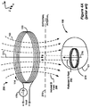
- FIG 4A shows a primary coil 130 configured for transcutaneously charging the IPG 100 via inductive coupling in accordance with the prior art.
- the charger 208 comprises a primary coil 130, through which an AC current 114 is passed via an AC current source 170.
- This current 114 produces induced magnetic field 290, which is illustrated as a plurality of flux lines 160.
- Flux lines 160 are essentially perpendicular to the surface of the skin 278 where they pass through its surface.
- the magnetic flux lines 160 near the center of the primary coil 130 are substantially parallel to the central axis 275 of the coil.
- a corresponding coil 270 within the IPG 100 transforms this magnetic energy into an electrical current, which is rectified and used by circuitry to charge a battery 180 within the IPG 100 as explained previously.
- the distance between the charger 208 and the IPG 100 is typically on the order of about 1-5 centimeters.
- the primary and secondary coils 130 and 270 are substantially in the shape of a circular loop, and are typically formed of several turns of wire, as one skilled in the art will appreciate. However, it will be recognized that the substantially circular shape of the coils 130 and 270 are merely illustrative.
- the turns of the primary coil 130 define a center opening or aperture having a central axis 275. It will be recognized that the surface of the skin 278 is not always flat. Hence, the central axis 275 of the primary coil 130 is sometimes only approximately or substantially perpendicular to the surface of the skin 278.
- the induced magnetic field 290 produces eddy currents in the IPG's typically metallic case 101 or in other conductive structures within the IPG 100. Such eddy currents operate to produce a reflected magnetic field 295, which operates to change the mutual inductance of the primary coil 130, effectively "detuning" the coil. Such detuning changes Vcoil, the voltage used to produce the current in the primary coil 130. Accordingly, from monitoring Vcoil, the relative coupling between the external charger 208 and the IPG 100 can be inferred. Vcoil decreases as the coupling increases, which generally occurs when the external charger 208 and the IPG 100 are closer to one another.
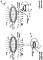
- Figure 4B shows an IPG 100 implanted relatively deeply within a patient, but otherwise well aligned from an axial perspective, i.e., coil axes 275 and 276 (see Fig. 4A ) are not offset from each other.
- Figure 4C shows an IPG 100 implanted relatively shallowly with a patient, but with poor alignment, i.e., coil axes 275 and 276 (see Fig. 4A ) are offset to a large degree.
- Figure 5A shows one embodiment of an improved external charger 210 with the ability to determine the relative position of an implanted device, and thus maximize coupling by indicating to the user how to improve charger/device alignment.
- four field sensing coils 230 are arranged into two pairs, 230x and 230y, of two connected sensing coils each.
- Each of the pairs of sensing coils 230x and 230y are positioned within primary coil 130 and such that the plurality of sensing coils are wound around axes that are parallel to the central axis 275 ( Figure 5B ).
- the field sensing coils 230 are designed to detect the amount of the reflected magnetic field 295 passing through them.
- Each pair 230x and 230y straddles the central axis 275 ( Figure 5B ) of the primary coil 130, such that the coils in each pair are equidistant from the central axis 275 and opposite each other.
- the pairs 230x and 230y are positioned orthogonally with respect to each other.
- Figure 5B shows a primary coil 130 configured for transcutaneously charging the IPG 100 via inductive coupling with sensing coils 230 arranged in accordance with the embodiment shown in Figure 5A .
- the position of the implant in both the x- and y-directions can be determined by the external charger 210's position indication circuitry 279 ( Figures 5C-5F ). Audio and/or visual feedback of the implant position can then be communicated to the patient to improve alignment of the charger.
- alignment of the primary coil 130 relative to the IPG 100 is determined by alignment sensing circuitry 281.
- Figure 5C shows one potential arrangement of a pair of sensing coils 230x for the improved external charger 210 that is depicted in Figures 5A and 5B .
- sensing coils 230x1 and 230x2- which are used to determine the IPG 100's misalignment with the external charger 210 in the x-direction-are shown for the sake of simplicity.
- a complete external charger 210 utilizing this embodiment will also have a corresponding pair of sensing coils 230y1 and 230y2 to measure misalignment in the y-direction, as is seen in Figure 5D and explained in further detail below.
- each sensing coil 230x and 230y are not connected to each other, i.e., each sensing coil 230x has one terminal connected to ground and the other terminal connected to a detector 274 that outputs a signal indicative of the voltage measured at each sensing coil 230x.
- Each detector 274 may be implemented as a half-wave rectifier using a single diode, for example.
- the output signal from each detector 274 in a sensing coil pair is then sent to an instrumentation amplifier 273x which, as is known to one of skill in the art, amplifies the difference between the two signals fed into it.
- the output 272x of the instrumentation amplifier 273x is an error indication signal, also known as an "error voltage.”
- the error voltages indicate alignment of the external charger 210 and the implantable medical device 100 with respect to a particular direction. In the case of x-error voltages and y-error voltages, the directions are perpendicular to each other.
- the voltages across each sensing coil within each sensing coil pair are compared to each other to produce an error voltage with respect to a particular direction.
- alignment sensing circuitry 281 derives a first indicator and a second indicator, wherein the first and second indicators indicate misalignment with respect to first and second directions.
- the outputs 272x and 272y are then converted from analog signals into digital signals and then sent to the improved external charger 210's position indication circuitry 279 so that the location of the implantable medical device 100 can be determined and appropriate instruction can be delivered to the user as to how to improve the external charger 210's alignment with the implantable medical device 100.
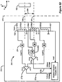
- FIG. 5D shows a circuit diagram depicting the alignment sensing circuitry 281 of the improved external charger 210 depicted in Figure 5C .
- each sensing coil 230 in the external charger 210 is connected to a detector 274.
- the output signal from each detector 274 in a "sensing coil pair," e.g., the detectors measuring the voltage at sensing coils 230x1 and 230x2 (which output signals are labeled in Figure 5D as VoilX1 and VcoilX2, respectively), is then sent to an instrumentation amplifier 273x which, as explained above, amplifies the difference between the two signals fed into it.
- the voltage detected at sensing coil 230x1 will be lower, say 50V, than the voltage detected at sensing coil 230x2, say 52V.
- This difference of positive two volts (VcoilX2 - VcoilX1) will cause instrumentation amplifier 273x to output a positive voltage signal.
- the voltage at sensing coil 230x1 will be higher, say 52V, than the voltage detected at sensing coil 230x2, say 50V. In this case, the difference of negative two volts will cause instrumentation amplifier 273x to output a negative voltage signal.
- the magnitude of the signal output by instrumentation amplifier 273x is directly proportional to the difference in magnitude between VcoilX1 and VcoilX2.
- the magnitude of the difference also indicates relative closeness of the primary coil 130 and the IPG 100. For example, if the voltages measured at 230x1 and 230x2 were 45V and 57V, respectively, instead of 50V and 52V as in the example above, the difference between the signals would be 12V, and the magnitude of the signal output by instrumentation amplifier 273x would be greater than in the 52V/50V example.
- instrumentation amplifier 273x in the 45V/57V example would indicate to position indication circuitry 279 that IPG 100 was located even further towards sensing coil 230x1 in the 45V/57V scenario than it was in the 50V/52V scenario.
- this embodiment is able to provide detailed information about the IPG 100's relative location in the x-direction.
- sensing coils 230y1 and 230y2 are simultaneously being carried out to determine the IPG 100's relative location in the y-direction, thus allowing external charger 210 to give a complete picture of IPG 100's location.
- the sensing coils 230 in this embodiment are arranged in the same plane as the primary coil 130, the measured magnetic field strength will have a large bias due to coupling from the primary coil 130.
- the difference between 52V and 50V is not very large (i.e., 2V) when compared to the absolute voltages being measured on the sensing coils.
- sensing coils 230x1 and 230x2 in this embodiment are connected to each other in series and "end-to-end."
- the beginning of one sensing coil, i.e., the 'A' Terminal as shown in Figure 5E could be connected to the beginning, i.e., 'A' Terminal, of another sensing coil.
- the terms "beginning" and “end”-and the designations 'A' Terminal and 'B' Terminal- are relative to the sensing coil, and are defined by the direction of the induced magnetic field, which should be the same for each sensing coil in a sensing coil pair. Connecting the sensing coils end-to-end in that manner cancels out the common mode AC voltage between sensing coil 230x1 and sensing coil 230x2. In other words, the voltage measured on the 'A' terminal of sensing coil 230x1 will be the difference of the voltages across sensing coils 230x1 and 230x2.
- the manner in which the coils are connected essentially performs the work of the instrumentation amplifier 273, which was described above in reference to Figures 5C and 5D , thus obviating the need for instrumentation amplifiers in this embodiment.
- the embodiment of Figures 5E and 5F would simply output a 2V signal to synchronous detector 284. This would very clearly be a non-zero signal, indicating misalignment of the external charger 210 and the IPG 100. There would be no-need to compare two different, relatively large voltage measurements and amplify the resulting difference with enough resolution to get meaningful information, as was done in the embodiment of Figures 5C and 5D .
- the only measurement that needs to be taken in the embodiment of Figures 5E and 5F is the magnitude of the output voltage for each sensing coil pair.
- this embodiment would result in a net voltage of zero at synchronous detector 284 when IPG 100 is centered symmetrically with respect to sensing coils 230x1 and 230x2.
- synchronous detector 284 will also need to be connected to a timing reference signal, which is not shown for simplicity.
- the outputs 272x and 272y of each synchronous detector 284x and 284y are error indication signals, also known as an "error voltages.”
- the error voltages indicate alignment of the external charger 210 and the implantable medical device 100 with respect to a particular direction. In the case of x-error voltages and y-error voltages, the directions are perpendicular to each other. In this embodiment, the voltages across each sensing coil pair are measured to produce an error voltage with respect to a particular direction. The error voltages are then converted from an analog signal into a digital signal and sent to the improved external charger 210's position indication circuitry 279 so that the location of the implant 100 can be determined and appropriate instructions can be delivered to the user as to how to improve the charger 210's alignment with IPG 100.
- FIG. 5G shows a scenario where an implantable medical device 100 is deeply implanted in the patient's body but well aligned with external charger 210.
- each of the field sensing coils 230 would have a similar Vcoil because each coil would pick up an equivalent reflected magnetic flux, i.e., VcoilX1, VcoilX2, VcoilY1, and VcoilY2 would all be equal.
- VcoilX1, VcoilX2, VcoilY1, and VcoilY2 would all be equal.
- the differences between the measured voltages of the two sensing coils in each of the sensing coil pairs would be close to zero, and the position indication circuitry 279 would determine that the external charger 210 was properly, i.e., symmetrically, aligned with the IPG 100.
- Figure 5H shows a scenario where an implantable medical device 100 is shallowly implanted in the patient's body but poorly aligned with external charger 210; specifically, it is skewed in the y-direction.
- a prior art external charger would not be able to distinguish between the scenario presented in Figure 5G and the scenario presented in Figure 5H .
- field sensing coil 230y2 measures a lower Vcoil (VcoilY2) than sensing coil 230y1 (VcoilY1) because sensing coil 230y2 picks up a disproportionately larger amount of reflected magnetic flux.
- the alignment sensing circuitry 281 compares the VcoilY1 and VcoilY2 values. In this scenario, it would result in a determination that VcoilY2 is smaller than VcoilY1 and alignment sensing circuitry 281 would output a negative "Y-error voltage" value 272y. This signal would then be converted into a digital signal, sent to position indication circuitry 279, and interpreted to mean that the IPG 100 was actually closer to sensing coil 230y2 than it was to sensing coil 230y1, i.e., that the charger 210 was too far to the left as illustrated.
- the external charger 210 would then indicate to the user how to correct the alignment problem, i.e., by instructing the user to move the charger 210 to the right, to maximize the electrical coupling of external charger 210 and implantable medical device 100.
- the same processing is simultaneously carried out by sensing coils 230x1 and 230x2 to report information about the IPG 100's location in the x-direction.
- the reflected magnetic field 295 from the implanted device 100 is not very strong, especially when the implanted device 100 is implanted deeply within the patient. Thus, it can be difficult to detect very small differences in the voltages across each of the sensing coils 230. The resolution of the measurements may have to be high for the circuitry to be able to notice the small differences in voltage. Additionally, due to the constantly changing nature of the electric field caused by the user's breathing and heart beat, the signal from all sensing coils 230 should be measured nearly simultaneously for a proper comparison.
- Figure 6A shows an alternative embodiment of an improved external charger 210 with the ability to determine the position of an implanted device.
- two or more cylindrical field sensing coils 240a-b are arranged within the primary coil 130 and wound around axes perpendicular to the central axis 275 of primary coil 130. Since the axes of the sensing coils 240a-b are perpendicular to the axis of the primary coil 130, coupling between the primary coil 130 and the sensing coils 240a-b is mitigated. The sensing coils 240a-b are therefore more likely to be affected by the magnetic fields reflected from the implant 100.
- sensing coil 240 When a sensing coil 240 is placed with its axis perpendicular to the direction of the magnetic field, i.e., in perfect alignment with the implanted device 100, the voltage across sensing coils 240a and 240b equals zero. With misalignment, however, the reflected magnetic field 295 contains components that are tangential to the axis of the sensing coils 240a-b, resulting in a non-zero voltage. To measure this tangential component and, by this measurement, to estimate a misalignment, it is preferred to place sensing coils 240a-b in the center of primary coil 130, with their axes lying in the primary coil 130 plane and oriented to measure misalignment in a particular axial direction.
- one sensing coil 240b is needed to detect the misalignment of the implant 100 in the x-direction
- another sensing coil 240a is needed to detect the misalignment of the implant 100 in the y-direction.
- the coils may be constructed as, for example, air-core coils or ferrite-core coils.
- Figure 6B shows a circuit diagram depicting the alignment sensing circuitry 281 of the improved external charger 210 depicted in Figure 6A .
- Primary coil 130 is powered by amplifier 252, which is excited by oscillator 251.
- a pair of mixers 254a and 254b, which are referenced to the excitation voltage, Ve, are used to detect the direction of the magnetic flux going through field sensing coils 240a and 240b, respectively. Because the voltage across field sensing coils 240a and 240b and the excitation voltage, Ve, could be out of phase, additional phase shifter 253 is used to equalize the phases.
- Output from the mixers 254a and 254b are filtered by low pass filters 255a and 255b, respectively, to get an x-error voltage and a y-error voltage, the magnitudes of which represent the misalignment of the primary coil 130 and the implanted device 100.
- the magnitude information is sent to the external charger 210's position indication circuitry 279, wherein calculations are performed to determine the degree and direction of misalignment 259 of the implanted device 100.
- Indication signals for the user are then generated and sent to any of various display or indication apparatuses, as are described below. Insert piece 241 and cylinder holders 242 and 243 are not shown in Figure 6B for simplicity.
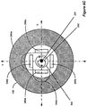
- Figure 6C shows a top down view of one of many possible mechanical designs for the improved external charger apparatus pictured in Figures 6A and 6B .
- field sensing coils 240a and 240b have to be precisely balanced. It may not be mechanically practical to balance the halves of the sensing coils 240a and 240b by physically moving or tilting them, although that is possible. It may instead be easier to "tilt" the magnetic field of the sensing coils 240a and 240b.
- An insert, 241 typically a small piece of material with high magnetic permeability such as ferrite or powdered iron, can be used for this purpose.
- the larger holder cylinder 243 can then be rotated inside the overall coil system. Insert piece 241 is preferably inserted into the small cylinder 242 asymmetrically, shifted to the edge of the cylinder. The small cylinder 242 is then inserted asymmetrically into the larger holder cylinder 243. By rotating the smaller cylinder 242, the displacement between the insert 241 and the coil system's main axis can be changed from zero to a maximum value. By rotating the larger holder cylinder 243, the direction of the displacement will be changed, and the sensing coils 240a and 240b may be precisely balanced so that they are able to detect small distortions in the reflected magnetic field 295.
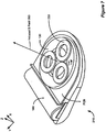
- Figure 7 shows another embodiment of an improved external charger 210 with the ability to determine the relative position of an implanted device, and thus maximize coupling by indicating to the user how to improve charger/device alignment.
- Previous embodiments used x-y based sensors.
- position can also be "triangulated” using an embodiment with three sensing coils positioned triangularly with respect to the central axis 275 of the primary coil.
- three field sensing coils 230 are arranged within the primary coil 130 in a plane parallel to the primary coil 130.
- the field sensing coils 230 are designed to detect the amount of the reflected magnetic field 295 passing through them.
- the cross sectional areas of the sensing coils 230 should be maximized to increase sensitivity to the reflected magnetic field 295.
- the coils 230 may be constructed either as air-core coils or ferrite-core coils. By comparing the relative reflected magnetic field strengths induced in the sensing coils 230, the position of the implant can be "triangulated," i.e., determined by the external charger 210's position indication circuitry 279 ( Figures 5C-5F ). Such triangulation techniques may also be applied to the coils 240 of Figures 6A-6C .
- Figure 8 shows a block diagram of an improved alignment detection system comprising an improved external charger 210 for generating a magnetic field, including the field sensing coils 235 (which could consist of either field sensing coils 230, field sensing coils 240, or other similar coils), alignment sensing circuitry 281 for measuring reflections of the magnetic field, and the position indication circuitry 279.
- the implantable device's circuitry 228 is similar to that described in reference to Figure 2 above, and is shown in a block for simplicity.
- Alignment sensing circuitry 281 comprises the circuitry for reading the field sensing coils 235 and may be affixed to the PCB of the external charger 210, as mentioned above.
- Alignment sensing circuitry 281 sends the field sensing coil information to the position indication circuitry 279, which discerns the aligmnent between the implanted device 100 and the external charger 210.
- Position indication circuitry 279 then indicates to the user a direction in which the external charger 210 should be moved to improve the alignment of the external charger 210 relative to the implantable medical device 100.
- Such indication may occur in a variety of ways, including, but not limited to: activating visual indicators, such as LED lights 295 which can be configured to light up on the surface of the external charger 210 (See Figure 10 ); activating audible indicators, such as beeps or verbal commands to the user; or activating tactile indicators, such as vibrating certain sides of the external charger 210 to indicate that the external charger 210 needs to be moved in that direction.
- activating visual indicators such as LED lights 295 which can be configured to light up on the surface of the external charger 210 (See Figure 10 )
- activating audible indicators such as beeps or verbal commands to the user
- tactile indicators such as vibrating certain sides of the external charger 210 to indicate that the external charger 210 needs to be moved in that direction.
- the external charger 210 may optionally transmit, via communications link 250, misalignment information to another external device for controlling the therapeutic settings of the implantable medical device, e.g., remote control 218.
- the external device may then indicate how the external charger 210 should be moved to improve the alignment of the external charger 210 relative to the implantable medical device 100.
- Figure 9 is a flowchart detailing a technique for assuring the proper alignment of an external charger 210 to an IPG 100.
- the user places external charger 210 against the surface of his body 278 in the known vicinity of IPG 100 (310).
- the patient will activate the external charger 210 and begin charging IPG 100 (320).
- the default setting for external charger 210 is maximum power output. As long as external charger doesn't receive an indication that IPG 100 is fully charged (330), it will continue to charge IPG 100.
- alignment sensing circuitry 281 in the external charger 210 senses the charger's alignment with the IPG 100 based at least in part on electrical measurements taken from the plurality of sensing coils 235 in the external charger 210, and position indication circuitry 279 calculates the IPG 100's location (340). This calculation occurs in real time (340) so that, any time alignment becomes poor, corrective action can be indicated to the user and taken in subsequent steps. If IPG 100 and the external charger 210 are properly aligned (350), external charger 210 continues to charge the IPG 100's internal power source 180 until receiving indication that IPG 100 is fully charged (330).
- the external charger 210 determines that IPG 100 and the external charger 210 are not properly aligned (350)
- the external charger 210 will indicate to the user (via one of the various methods discussed above) which direction to move the external charger 210 to improve alignment (360) while still continuing to charge IPG 100.
- the external charger 210 determines that the IPG 100's internal power source 180 is fully charged (330), it will indicate via an audible beep or other visual indication to the user that the charging process has completed (370).
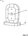
- Figure 10 shows an improved external charger 210 for charging an implantable device.
- the external charger 210 is shown sitting in a base unit 296.
- four arrow-shaped LED lights 295 are arranged on the surface of the external charger 210, with one arrow-shaped LED light pointing towards each edge of external charger 210.
- position indication circuitry 279 determines in which direction the external charger 210 should be moved to provide better alignment with implantable device 100, it can send an appropriate control signal to illuminate one or more of the LED lights 295 to indicate that direction to the user.
- position determination circuitry 279 When position determination circuitry 279 has detected that there is a satisfactory degree of alignment between the external charger 210's primary coil 130 and the implantable device, position indication circuitry 279 will send a control signal to turn off each LED light 295 until it again senses a misalignment condition during charging.
Landscapes
- Engineering & Computer Science (AREA)
- Power Engineering (AREA)
- Health & Medical Sciences (AREA)
- Computer Networks & Wireless Communication (AREA)
- Radiology & Medical Imaging (AREA)
- Biomedical Technology (AREA)
- Nuclear Medicine, Radiotherapy & Molecular Imaging (AREA)
- Life Sciences & Earth Sciences (AREA)
- Animal Behavior & Ethology (AREA)
- General Health & Medical Sciences (AREA)
- Public Health (AREA)
- Veterinary Medicine (AREA)
- General Physics & Mathematics (AREA)
- Physics & Mathematics (AREA)
- Electrotherapy Devices (AREA)
- Charge And Discharge Circuits For Batteries Or The Like (AREA)
Applications Claiming Priority (2)
| Application Number | Priority Date | Filing Date | Title |
|---|---|---|---|
| US12/498,049 US8473066B2 (en) | 2009-07-06 | 2009-07-06 | External charger for a medical implantable device using field sensing coils to improve coupling |
| PCT/US2010/040935 WO2011005696A1 (en) | 2009-07-06 | 2010-07-02 | An improved external charger for a medical implantable device using field sensing coils to improve coupling |
Publications (3)
| Publication Number | Publication Date |
|---|---|
| EP2451526A1 EP2451526A1 (en) | 2012-05-16 |
| EP2451526B1 EP2451526B1 (en) | 2013-06-12 |
| EP2451526B2 true EP2451526B2 (en) | 2017-01-25 |
Family
ID=42610067
Family Applications (1)
| Application Number | Title | Priority Date | Filing Date |
|---|---|---|---|
| EP10731691.1A Active EP2451526B2 (en) | 2009-07-06 | 2010-07-02 | An improved external charger for a medical implantable device using field sensing coils to improve coupling |
Country Status (7)
| Country | Link |
|---|---|
| US (2) | US8473066B2 (enExample) |
| EP (1) | EP2451526B2 (enExample) |
| JP (1) | JP5469245B2 (enExample) |
| AU (1) | AU2010270742B2 (enExample) |
| CA (1) | CA2763052A1 (enExample) |
| ES (1) | ES2416107T5 (enExample) |
| WO (1) | WO2011005696A1 (enExample) |
Cited By (2)
| Publication number | Priority date | Publication date | Assignee | Title |
|---|---|---|---|---|
| US11152819B2 (en) | 2018-02-09 | 2021-10-19 | Medtronic, Inc. | Recharge of implanted medical devices |
| US11571127B2 (en) | 2017-01-26 | 2023-02-07 | Medtronic, Inc. | Recharge of implanted medical devices |
Families Citing this family (208)
| Publication number | Priority date | Publication date | Assignee | Title |
|---|---|---|---|---|
| AU2003901696A0 (en) | 2003-04-09 | 2003-05-01 | Cochlear Limited | Implant magnet system |
| US8068918B2 (en) | 2007-03-09 | 2011-11-29 | Enteromedics Inc. | Remote monitoring and control of implantable devices |
| SE531177C2 (sv) | 2007-05-24 | 2009-01-13 | Cochlear Ltd | Distans för implantat |
| US8532787B2 (en) * | 2007-05-31 | 2013-09-10 | Enteromedics Inc. | Implantable therapy system having multiple operating modes |
| US10854378B2 (en) * | 2009-02-23 | 2020-12-01 | Triune Ip Llc | Wireless power transmittal |
| US9433750B2 (en) | 2009-06-16 | 2016-09-06 | The Board Of Trustees Of The Leland Stanford Junior University | Method of making and using an apparatus for a locomotive micro-implant using active electromagnetic propulsion |
| US8634928B1 (en) * | 2009-06-16 | 2014-01-21 | The Board Of Trustees Of The Leland Stanford Junior University | Wireless power transmission for implantable medical devices |
| US8321029B2 (en) | 2009-09-18 | 2012-11-27 | Boston Scientific Neuromodulation Corporation | External charger usable with an implantable medical device having a programmable or time-varying temperature set point |
| US8311638B2 (en) | 2009-10-15 | 2012-11-13 | Boston Scientific Neuromodulation Corporation | External charger for a medical implantable device using field inducing coils to improve coupling |
| US9030159B2 (en) | 2010-03-26 | 2015-05-12 | Boston Scientific Neuromodulation Corporation | Inductive charger with magnetic shielding |
| US8594806B2 (en) | 2010-04-30 | 2013-11-26 | Cyberonics, Inc. | Recharging and communication lead for an implantable device |
| US9700730B2 (en) | 2010-05-07 | 2017-07-11 | Boston Scientific Neuromodulation Corporation | External charger with customizable magnetic charging field |
| US9044616B2 (en) | 2010-07-01 | 2015-06-02 | Boston Scientific Neuromodulation Corporation | Charging system for an implantable medical device employing magnetic and electric fields |
| US8994325B2 (en) | 2010-11-17 | 2015-03-31 | Boston Scientific Neuromodulation Corporation | External charger for an implantable medical device having at least one moveable charging coil |
| US8954148B2 (en) | 2011-06-28 | 2015-02-10 | Greatbatch, Ltd. | Key fob controller for an implantable neurostimulator |
| US20130197607A1 (en) | 2011-06-28 | 2013-08-01 | Greatbatch Ltd. | Dual patient controllers |
| US20130006330A1 (en) | 2011-06-28 | 2013-01-03 | Greatbatch, Ltd. | Dual patient controllers |
| US8700175B2 (en) * | 2011-07-19 | 2014-04-15 | Greatbatch Ltd. | Devices and methods for visually indicating the alignment of a transcutaneous energy transfer device over an implanted medical device |
| US9260026B2 (en) | 2011-07-21 | 2016-02-16 | Ut-Battelle, Llc | Vehicle to wireless power transfer coupling coil alignment sensor |
| JP5770556B2 (ja) * | 2011-07-29 | 2015-08-26 | 東光株式会社 | ワイヤレス電力伝送装置および相対位置検出方法 |
| US9314642B2 (en) | 2011-10-13 | 2016-04-19 | Boston Scientific Neuromodulation Corporation | Closed loop charger for an implantable medical device system employing reflected impedance modulation |
| US9446254B2 (en) | 2011-10-13 | 2016-09-20 | Boston Scientific Neuromodulation Corporation | Charger alignment in an implantable medical device system employing reflected impedance modulation |
| US9186520B2 (en) | 2012-01-16 | 2015-11-17 | Boston Scientific Neuromodulation Corporation | Automatic on-off charger for an implantable medical device |
| DE102012201073B4 (de) * | 2012-01-25 | 2014-05-08 | Dualis Medtech Gmbh | Tragevorrichtung zum Tragen einer Sendespule am Körper eines Patienten |
| US20150018728A1 (en) | 2012-01-26 | 2015-01-15 | Bluewind Medical Ltd. | Wireless neurostimulators |
| JP5997554B2 (ja) * | 2012-02-10 | 2016-09-28 | 東光株式会社 | ワイヤレス電力伝送装置 |
| JP2013192391A (ja) * | 2012-03-14 | 2013-09-26 | Sony Corp | 検知装置、受電装置、送電装置及び非接触給電システム |
| WO2013164831A1 (en) * | 2012-05-03 | 2013-11-07 | Powermat Technologies Ltd. | System and method for triggering power transfer across an inductive power coupling and non resonant transmission |
| US9817078B2 (en) | 2012-05-10 | 2017-11-14 | Allegro Microsystems Llc | Methods and apparatus for magnetic sensor having integrated coil |
| US11871901B2 (en) | 2012-05-20 | 2024-01-16 | Cilag Gmbh International | Method for situational awareness for surgical network or surgical network connected device capable of adjusting function based on a sensed situation or usage |
| CN104540543B (zh) * | 2012-07-03 | 2016-08-17 | Med-El电气医疗器械有限公司 | 具有成角度磁化的mri安全植入体磁体 |
| WO2014018967A1 (en) | 2012-07-27 | 2014-01-30 | Thoratec Corporation | Self-tuning resonant power transfer systems |
| US10525181B2 (en) | 2012-07-27 | 2020-01-07 | Tc1 Llc | Resonant power transfer system and method of estimating system state |
| US9805863B2 (en) | 2012-07-27 | 2017-10-31 | Thoratec Corporation | Magnetic power transmission utilizing phased transmitter coil arrays and phased receiver coil arrays |
| WO2014018973A1 (en) | 2012-07-27 | 2014-01-30 | Thoratec Corporation | Resonant power transmission coils and systems |
| US9592397B2 (en) | 2012-07-27 | 2017-03-14 | Thoratec Corporation | Thermal management for implantable wireless power transfer systems |
| US10383990B2 (en) | 2012-07-27 | 2019-08-20 | Tc1 Llc | Variable capacitor for resonant power transfer systems |
| WO2014018971A1 (en) | 2012-07-27 | 2014-01-30 | Thoratec Corporation | Resonant power transfer systems with protective algorithm |
| US10291067B2 (en) | 2012-07-27 | 2019-05-14 | Tc1 Llc | Computer modeling for resonant power transfer systems |
| US9225190B2 (en) | 2012-09-07 | 2015-12-29 | Manufacturers And Traders Trust Company | Implant current controlled battery charging based on temperature |
| US9142989B2 (en) | 2012-09-07 | 2015-09-22 | Greatbatch Ltd. | Method of minimizing interruptions to implantable medical device recharging |
| US9209634B2 (en) | 2012-09-07 | 2015-12-08 | Greatbatch Ltd. | Method of improving battery recharge efficiency by statistical analysis |
| WO2014087337A1 (en) | 2012-12-06 | 2014-06-12 | Bluewind Medical Ltd. | Delivery of implantable neurostimulators |
| JP6160288B2 (ja) * | 2013-03-04 | 2017-07-12 | 船井電機株式会社 | 給電装置 |
| US10373756B2 (en) | 2013-03-15 | 2019-08-06 | Tc1 Llc | Malleable TETs coil with improved anatomical fit |
| WO2014145664A1 (en) | 2013-03-15 | 2014-09-18 | Thoratec Corporation | Integrated implantable tets housing including fins and coil loops |
| US10145908B2 (en) | 2013-07-19 | 2018-12-04 | Allegro Microsystems, Llc | Method and apparatus for magnetic sensor producing a changing magnetic field |
| US10495699B2 (en) | 2013-07-19 | 2019-12-03 | Allegro Microsystems, Llc | Methods and apparatus for magnetic sensor having an integrated coil or magnet to detect a non-ferromagnetic target |
| CN105264736B (zh) * | 2013-07-29 | 2017-05-10 | 艾尔弗雷德·E·曼科学研究基金会 | 通过无线电链路进行植入物充电场控制 |
| CN105263572B (zh) * | 2013-07-29 | 2017-10-17 | 艾尔弗雷德·E·曼科学研究基金会 | 用于植入式装置的高效率磁链路 |
| WO2015021144A1 (en) * | 2013-08-06 | 2015-02-12 | Momentum Dynamics Corporation | A method of and apparatue for detecting coil alignment error in wirelss inductive power transmission |
| US9496733B2 (en) | 2013-09-13 | 2016-11-15 | Boston Scientific Neuromodulation Corporation | Optical communications between an implantable medical device and external charger |
| US9425640B2 (en) * | 2013-09-26 | 2016-08-23 | The Charles Stark Draper Laboratory, Inc. | System and method of inductive charging and localization through using multiple primary inductive coils to detect the induced voltage of a secondary inductive coil |
| US9339660B2 (en) | 2013-10-04 | 2016-05-17 | Boston Scientific Neuromodulation Corporation | Implantable medical device with one or more magnetic field sensors to assist with external charger alignment |
| US9861825B2 (en) * | 2013-11-08 | 2018-01-09 | Boston Scientific Neuromodulation Corporation | Orientation and placement of inductive components to minimize noise coupling to a communication coil in an implantable medical device |
| EP3072210B1 (en) | 2013-11-11 | 2023-12-20 | Tc1 Llc | Resonant power transfer systems with communications |
| WO2015070200A1 (en) | 2013-11-11 | 2015-05-14 | Thoratec Corporation | Resonant power transfer systems with communications |
| EP3069358B1 (en) * | 2013-11-11 | 2019-06-12 | Tc1 Llc | Hinged resonant power transfer coil |
| WO2015106228A1 (en) * | 2014-01-12 | 2015-07-16 | Global Cardiac Monitor, Inc. | Diagnostic device for remote sensing and transmitting biophysiological signals |
| WO2015134871A1 (en) | 2014-03-06 | 2015-09-11 | Thoratec Corporation | Electrical connectors for implantable devices |
| WO2015196164A2 (en) | 2014-06-21 | 2015-12-23 | Accelemed, Llc | Method and apparatus for neuromodulation treatments of pain and other conditions |
| DE102015112098A1 (de) | 2014-07-25 | 2016-01-28 | Minnetronix, Inc. | Spulenparameter und Steuerung |
| US9855376B2 (en) | 2014-07-25 | 2018-01-02 | Minnetronix, Inc. | Power scaling |
| US10091594B2 (en) | 2014-07-29 | 2018-10-02 | Cochlear Limited | Bone conduction magnetic retention system |
| EP3826104B1 (en) | 2014-09-22 | 2023-05-03 | Tc1 Llc | Antenna designs for communication between a wirelessly powered implant to an external device outside the body |
| EP3204989B1 (en) | 2014-10-06 | 2019-08-21 | Tc1 Llc | Multiaxial connector for implantable devices |
| US9929584B2 (en) | 2014-10-30 | 2018-03-27 | Boston Scientific Neuromodulation Corporation | External charging coil assembly for charging a medical device |
| US9823092B2 (en) | 2014-10-31 | 2017-11-21 | Allegro Microsystems, Llc | Magnetic field sensor providing a movement detector |
| IL243231B (en) | 2014-12-22 | 2019-05-30 | Newpace Ltd | System and method for wireless recharging of a flexible subcutaneously implanted medical device |
| US10342908B2 (en) | 2015-01-14 | 2019-07-09 | Minnetronix, Inc. | Distributed transformer |
| US10406267B2 (en) | 2015-01-16 | 2019-09-10 | Minnetronix, Inc. | Data communication in a transcutaneous energy transfer system |
| US10079508B2 (en) * | 2015-01-22 | 2018-09-18 | Integrated Device Technology, Inc. | Apparatuses and related methods for detecting magnetic flux field characteristics with a wireless power receiver |
| US10132650B2 (en) * | 2015-01-22 | 2018-11-20 | Integrated Device Technology, Inc. | Apparatuses and related methods for detecting magnetic flux field characteristics with a wireless power transmitter |
| US10193390B2 (en) * | 2015-03-06 | 2019-01-29 | Mediatek Inc. | Wireless power transmitter configuration for power transmission through a partition |
| DE102015113723A1 (de) * | 2015-04-09 | 2016-10-13 | Weidmüller Interface GmbH & Co. KG | Vorrichtung zur kontaktlosen induktiven Energieübertragung und Betriebsverfahren für eine derartige Vorrichtung |
| US10193395B2 (en) | 2015-04-14 | 2019-01-29 | Minnetronix, Inc. | Repeater resonator |
| US10130807B2 (en) | 2015-06-12 | 2018-11-20 | Cochlear Limited | Magnet management MRI compatibility |
| US20160381473A1 (en) | 2015-06-26 | 2016-12-29 | Johan Gustafsson | Magnetic retention device |
| US10148126B2 (en) | 2015-08-31 | 2018-12-04 | Tc1 Llc | Wireless energy transfer system and wearables |
| US10917730B2 (en) | 2015-09-14 | 2021-02-09 | Cochlear Limited | Retention magnet system for medical device |
| EP3902100A1 (en) | 2015-10-07 | 2021-10-27 | Tc1 Llc | Resonant power transfer systems having efficiency optimization based on receiver impedance |
| US10105540B2 (en) | 2015-11-09 | 2018-10-23 | Bluewind Medical Ltd. | Optimization of application of current |
| WO2017165410A1 (en) | 2016-03-21 | 2017-09-28 | Nalu Medical, Inc. | Devices and methods for positioning external devices in relation to implanted devices |
| US10576276B2 (en) | 2016-04-29 | 2020-03-03 | Cochlear Limited | Implanted magnet management in the face of external magnetic fields |
| JP6603423B2 (ja) * | 2016-05-24 | 2019-11-06 | シナジア メディカル | 埋め込み型医療装置に対して外部要素を位置合わせするためのセンタリングキットおよび対応する方法 |
| US10603501B2 (en) * | 2016-06-15 | 2020-03-31 | Boston Scientific Neuromodulation Corporation | External charger for an implantable medical device having at least one sense coil concentric with a charging coil for determining position |
| US10363426B2 (en) * | 2016-06-15 | 2019-07-30 | Boston Scientific Neuromodulation Corporation | External charger for an implantable medical device for determining position using phase angle or a plurality of parameters as determined from at least one sense coil |
| US11129996B2 (en) * | 2016-06-15 | 2021-09-28 | Boston Scientific Neuromodulation Corporation | External charger for an implantable medical device for determining position and optimizing power transmission using resonant frequency as determined from at least one sense coil |
| US10342984B2 (en) * | 2016-06-15 | 2019-07-09 | Boston Scientific Neuromodulation Corporation | Split coil for uniform magnetic field generation from an external charger for an implantable medical device |
| US10226637B2 (en) | 2016-06-15 | 2019-03-12 | Boston Scientific Neuromodulation Corporation | External charger for an implantable medical device having alignment and centering capabilities |
| US11471692B2 (en) * | 2016-06-15 | 2022-10-18 | Boston Scientific Neuromodulation Corporation | External charger for an implantable medical device for adjusting charging power based on determined position using at least one sense coil |
| US10112496B2 (en) * | 2016-07-12 | 2018-10-30 | Denso International America, Inc. | Vehicular wireless power transfer system with performance monitoring |
| US20180026470A1 (en) * | 2016-07-21 | 2018-01-25 | Boston Scientific Neuromodulation Corporation | External Charger for an Implantable Medical Device Having a Conductive Layer Printed or Deposited on an Inside Housing Surface |
| US10898292B2 (en) | 2016-09-21 | 2021-01-26 | Tc1 Llc | Systems and methods for locating implanted wireless power transmission devices |
| US11114884B2 (en) | 2016-09-30 | 2021-09-07 | Intel Corporation | Sensing coil system |
| US10124178B2 (en) | 2016-11-23 | 2018-11-13 | Bluewind Medical Ltd. | Implant and delivery tool therefor |
| US11595768B2 (en) | 2016-12-02 | 2023-02-28 | Cochlear Limited | Retention force increasing components |
| WO2018136592A2 (en) | 2017-01-18 | 2018-07-26 | Tc1 Llc | Systems and methods for transcutaneous power transfer using microneedles |
| US10632318B2 (en) | 2017-03-21 | 2020-04-28 | Boston Scientific Neuromodulation Corporation | External charger with three-axis magnetic field sensor to determine implantable medical device position |
| AU2018265016B2 (en) | 2017-05-09 | 2023-01-05 | Nalu Medical, Inc. | Stimulation apparatus |
| US10837943B2 (en) | 2017-05-26 | 2020-11-17 | Allegro Microsystems, Llc | Magnetic field sensor with error calculation |
| US11428755B2 (en) * | 2017-05-26 | 2022-08-30 | Allegro Microsystems, Llc | Coil actuated sensor with sensitivity detection |
| US10996289B2 (en) | 2017-05-26 | 2021-05-04 | Allegro Microsystems, Llc | Coil actuated position sensor with reflected magnetic field |
| US10888706B2 (en) | 2017-06-02 | 2021-01-12 | Boston Scientific Neuromodulation Corporation | External charger for an implantable medical device having a thermal diffuser |
| US20180353764A1 (en) | 2017-06-13 | 2018-12-13 | Bluewind Medical Ltd. | Antenna configuration |
| US11317919B2 (en) | 2017-10-30 | 2022-05-03 | Cilag Gmbh International | Clip applier comprising a clip crimping system |
| US11793537B2 (en) | 2017-10-30 | 2023-10-24 | Cilag Gmbh International | Surgical instrument comprising an adaptive electrical system |
| US11911045B2 (en) | 2017-10-30 | 2024-02-27 | Cllag GmbH International | Method for operating a powered articulating multi-clip applier |
| US11564756B2 (en) | 2017-10-30 | 2023-01-31 | Cilag Gmbh International | Method of hub communication with surgical instrument systems |
| US11801098B2 (en) | 2017-10-30 | 2023-10-31 | Cilag Gmbh International | Method of hub communication with surgical instrument systems |
| US11510741B2 (en) | 2017-10-30 | 2022-11-29 | Cilag Gmbh International | Method for producing a surgical instrument comprising a smart electrical system |
| US11291510B2 (en) | 2017-10-30 | 2022-04-05 | Cilag Gmbh International | Method of hub communication with surgical instrument systems |
| US11166772B2 (en) | 2017-12-28 | 2021-11-09 | Cilag Gmbh International | Surgical hub coordination of control and communication of operating room devices |
| US11612444B2 (en) | 2017-12-28 | 2023-03-28 | Cilag Gmbh International | Adjustment of a surgical device function based on situational awareness |
| US11026751B2 (en) | 2017-12-28 | 2021-06-08 | Cilag Gmbh International | Display of alignment of staple cartridge to prior linear staple line |
| US11678881B2 (en) | 2017-12-28 | 2023-06-20 | Cilag Gmbh International | Spatial awareness of surgical hubs in operating rooms |
| US20190206569A1 (en) | 2017-12-28 | 2019-07-04 | Ethicon Llc | Method of cloud based data analytics for use with the hub |
| US11744604B2 (en) | 2017-12-28 | 2023-09-05 | Cilag Gmbh International | Surgical instrument with a hardware-only control circuit |
| US11969142B2 (en) | 2017-12-28 | 2024-04-30 | Cilag Gmbh International | Method of compressing tissue within a stapling device and simultaneously displaying the location of the tissue within the jaws |
| US11666331B2 (en) | 2017-12-28 | 2023-06-06 | Cilag Gmbh International | Systems for detecting proximity of surgical end effector to cancerous tissue |
| US11076921B2 (en) | 2017-12-28 | 2021-08-03 | Cilag Gmbh International | Adaptive control program updates for surgical hubs |
| US11213359B2 (en) | 2017-12-28 | 2022-01-04 | Cilag Gmbh International | Controllers for robot-assisted surgical platforms |
| US11109866B2 (en) | 2017-12-28 | 2021-09-07 | Cilag Gmbh International | Method for circular stapler control algorithm adjustment based on situational awareness |
| US11903601B2 (en) | 2017-12-28 | 2024-02-20 | Cilag Gmbh International | Surgical instrument comprising a plurality of drive systems |
| WO2019133143A1 (en) | 2017-12-28 | 2019-07-04 | Ethicon Llc | Surgical hub and modular device response adjustment based on situational awareness |
| US11304763B2 (en) | 2017-12-28 | 2022-04-19 | Cilag Gmbh International | Image capturing of the areas outside the abdomen to improve placement and control of a surgical device in use |
| US10918310B2 (en) | 2018-01-03 | 2021-02-16 | Biosense Webster (Israel) Ltd. | Fast anatomical mapping (FAM) using volume filling |
| US10758310B2 (en) | 2017-12-28 | 2020-09-01 | Ethicon Llc | Wireless pairing of a surgical device with another device within a sterile surgical field based on the usage and situational awareness of devices |
| US11419630B2 (en) | 2017-12-28 | 2022-08-23 | Cilag Gmbh International | Surgical system distributed processing |
| US11937769B2 (en) | 2017-12-28 | 2024-03-26 | Cilag Gmbh International | Method of hub communication, processing, storage and display |
| US11389164B2 (en) | 2017-12-28 | 2022-07-19 | Cilag Gmbh International | Method of using reinforced flexible circuits with multiple sensors to optimize performance of radio frequency devices |
| US11771487B2 (en) | 2017-12-28 | 2023-10-03 | Cilag Gmbh International | Mechanisms for controlling different electromechanical systems of an electrosurgical instrument |
| US11589888B2 (en) | 2017-12-28 | 2023-02-28 | Cilag Gmbh International | Method for controlling smart energy devices |
| US11132462B2 (en) | 2017-12-28 | 2021-09-28 | Cilag Gmbh International | Data stripping method to interrogate patient records and create anonymized record |
| US20190201042A1 (en) | 2017-12-28 | 2019-07-04 | Ethicon Llc | Determining the state of an ultrasonic electromechanical system according to frequency shift |
| US20190201090A1 (en) | 2017-12-28 | 2019-07-04 | Ethicon Llc | Capacitive coupled return path pad with separable array elements |
| US11202570B2 (en) | 2017-12-28 | 2021-12-21 | Cilag Gmbh International | Communication hub and storage device for storing parameters and status of a surgical device to be shared with cloud based analytics systems |
| US12062442B2 (en) | 2017-12-28 | 2024-08-13 | Cilag Gmbh International | Method for operating surgical instrument systems |
| US11311306B2 (en) | 2017-12-28 | 2022-04-26 | Cilag Gmbh International | Surgical systems for detecting end effector tissue distribution irregularities |
| US11832899B2 (en) | 2017-12-28 | 2023-12-05 | Cilag Gmbh International | Surgical systems with autonomously adjustable control programs |
| US11324557B2 (en) | 2017-12-28 | 2022-05-10 | Cilag Gmbh International | Surgical instrument with a sensing array |
| US12096916B2 (en) | 2017-12-28 | 2024-09-24 | Cilag Gmbh International | Method of sensing particulate from smoke evacuated from a patient, adjusting the pump speed based on the sensed information, and communicating the functional parameters of the system to the hub |
| US10595887B2 (en) | 2017-12-28 | 2020-03-24 | Ethicon Llc | Systems for adjusting end effector parameters based on perioperative information |
| US11864728B2 (en) | 2017-12-28 | 2024-01-09 | Cilag Gmbh International | Characterization of tissue irregularities through the use of mono-chromatic light refractivity |
| JP2021509061A (ja) | 2017-12-28 | 2021-03-18 | エシコン エルエルシーEthicon LLC | 状況認識に基づく外科用デバイスの機能の調節 |
| US11896443B2 (en) | 2017-12-28 | 2024-02-13 | Cilag Gmbh International | Control of a surgical system through a surgical barrier |
| US11786251B2 (en) | 2017-12-28 | 2023-10-17 | Cilag Gmbh International | Method for adaptive control schemes for surgical network control and interaction |
| US12376855B2 (en) | 2017-12-28 | 2025-08-05 | Cilag Gmbh International | Safety systems for smart powered surgical stapling |
| US10892995B2 (en) | 2017-12-28 | 2021-01-12 | Ethicon Llc | Surgical network determination of prioritization of communication, interaction, or processing based on system or device needs |
| US11464559B2 (en) | 2017-12-28 | 2022-10-11 | Cilag Gmbh International | Estimating state of ultrasonic end effector and control system therefor |
| US11998193B2 (en) | 2017-12-28 | 2024-06-04 | Cilag Gmbh International | Method for usage of the shroud as an aspect of sensing or controlling a powered surgical device, and a control algorithm to adjust its default operation |
| US11147607B2 (en) | 2017-12-28 | 2021-10-19 | Cilag Gmbh International | Bipolar combination device that automatically adjusts pressure based on energy modality |
| US11818052B2 (en) | 2017-12-28 | 2023-11-14 | Cilag Gmbh International | Surgical network determination of prioritization of communication, interaction, or processing based on system or device needs |
| US11969216B2 (en) | 2017-12-28 | 2024-04-30 | Cilag Gmbh International | Surgical network recommendations from real time analysis of procedure variables against a baseline highlighting differences from the optimal solution |
| US11633237B2 (en) | 2017-12-28 | 2023-04-25 | Cilag Gmbh International | Usage and technique analysis of surgeon / staff performance against a baseline to optimize device utilization and performance for both current and future procedures |
| US12396806B2 (en) | 2017-12-28 | 2025-08-26 | Cilag Gmbh International | Adjustment of a surgical device function based on situational awareness |
| US11576677B2 (en) | 2017-12-28 | 2023-02-14 | Cilag Gmbh International | Method of hub communication, processing, display, and cloud analytics |
| US11257589B2 (en) | 2017-12-28 | 2022-02-22 | Cilag Gmbh International | Real-time analysis of comprehensive cost of all instrumentation used in surgery utilizing data fluidity to track instruments through stocking and in-house processes |
| US11857152B2 (en) | 2017-12-28 | 2024-01-02 | Cilag Gmbh International | Surgical hub spatial awareness to determine devices in operating theater |
| US11786245B2 (en) | 2017-12-28 | 2023-10-17 | Cilag Gmbh International | Surgical systems with prioritized data transmission capabilities |
| US11896322B2 (en) | 2017-12-28 | 2024-02-13 | Cilag Gmbh International | Sensing the patient position and contact utilizing the mono-polar return pad electrode to provide situational awareness to the hub |
| US11659023B2 (en) | 2017-12-28 | 2023-05-23 | Cilag Gmbh International | Method of hub communication |
| US11832840B2 (en) | 2017-12-28 | 2023-12-05 | Cilag Gmbh International | Surgical instrument having a flexible circuit |
| US11559308B2 (en) | 2017-12-28 | 2023-01-24 | Cilag Gmbh International | Method for smart energy device infrastructure |
| US11304699B2 (en) | 2017-12-28 | 2022-04-19 | Cilag Gmbh International | Method for adaptive control schemes for surgical network control and interaction |
| US11013563B2 (en) | 2017-12-28 | 2021-05-25 | Ethicon Llc | Drive arrangements for robot-assisted surgical platforms |
| US11376002B2 (en) | 2017-12-28 | 2022-07-05 | Cilag Gmbh International | Surgical instrument cartridge sensor assemblies |
| US12127729B2 (en) | 2017-12-28 | 2024-10-29 | Cilag Gmbh International | Method for smoke evacuation for surgical hub |
| US20190201112A1 (en) | 2017-12-28 | 2019-07-04 | Ethicon Llc | Computer implemented interactive surgical systems |
| WO2019135890A1 (en) | 2018-01-04 | 2019-07-11 | Tc1 Llc | Systems and methods for elastic wireless power transmission devices |
| US11986233B2 (en) | 2018-03-08 | 2024-05-21 | Cilag Gmbh International | Adjustment of complex impedance to compensate for lost power in an articulating ultrasonic device |
| US11464532B2 (en) | 2018-03-08 | 2022-10-11 | Cilag Gmbh International | Methods for estimating and controlling state of ultrasonic end effector |
| US11259830B2 (en) | 2018-03-08 | 2022-03-01 | Cilag Gmbh International | Methods for controlling temperature in ultrasonic device |
| US12303159B2 (en) | 2018-03-08 | 2025-05-20 | Cilag Gmbh International | Methods for estimating and controlling state of ultrasonic end effector |
| US11090047B2 (en) | 2018-03-28 | 2021-08-17 | Cilag Gmbh International | Surgical instrument comprising an adaptive control system |
| US11259806B2 (en) | 2018-03-28 | 2022-03-01 | Cilag Gmbh International | Surgical stapling devices with features for blocking advancement of a camming assembly of an incompatible cartridge installed therein |
| DE102018206727A1 (de) * | 2018-05-02 | 2019-11-07 | Kardion Gmbh | Energieübertragungssystem und Empfangseinheit zur drahtlosen transkutanen Energieübertragung |
| DE102018208555A1 (de) | 2018-05-30 | 2019-12-05 | Kardion Gmbh | Vorrichtung zum Verankern eines Herzunterstützungssystems in einem Blutgefäß, Verfahren zum Betreiben und Herstellverfahren zum Herstellen einer Vorrichtung und Herzunterstützungssystem |
| US20200129774A1 (en) * | 2018-10-28 | 2020-04-30 | Cardiac Pacemakers, Inc. | Magnet assembly and packaging |
| CN109672237B (zh) * | 2018-11-29 | 2024-03-22 | 苏州佳世达电通有限公司 | 可发光无线充电结构及显示器 |
| US10823586B2 (en) | 2018-12-26 | 2020-11-03 | Allegro Microsystems, Llc | Magnetic field sensor having unequally spaced magnetic field sensing elements |
| CN109617252B (zh) * | 2019-01-02 | 2023-01-24 | 京东方科技集团股份有限公司 | 无线充电装置、设备、系统及方法 |
| US11464511B2 (en) | 2019-02-19 | 2022-10-11 | Cilag Gmbh International | Surgical staple cartridges with movable authentication key arrangements |
| US11259807B2 (en) | 2019-02-19 | 2022-03-01 | Cilag Gmbh International | Staple cartridges with cam surfaces configured to engage primary and secondary portions of a lockout of a surgical stapling device |
| US11642537B2 (en) | 2019-03-11 | 2023-05-09 | Axonics, Inc. | Charging device with off-center coil |
| WO2021003439A1 (en) | 2019-07-02 | 2021-01-07 | Nalu Medical, Inc. | Stimulation apparatus |
| JP7285171B2 (ja) * | 2019-08-29 | 2023-06-01 | ローム株式会社 | ワイヤレス受電装置および電子機器 |
| US12420101B2 (en) | 2019-09-27 | 2025-09-23 | Cochlear Limited | Multipole magnet for medical implant system |
| US11280637B2 (en) | 2019-11-14 | 2022-03-22 | Allegro Microsystems, Llc | High performance magnetic angle sensor |
| US11237020B2 (en) | 2019-11-14 | 2022-02-01 | Allegro Microsystems, Llc | Magnetic field sensor having two rows of magnetic field sensing elements for measuring an angle of rotation of a magnet |
| US11931592B2 (en) | 2020-02-13 | 2024-03-19 | Cardiac Pacemakers, Inc. | Output circuitry for multiple-therapy implantable devices |
| US11717695B2 (en) | 2020-02-13 | 2023-08-08 | Cardiac Pacemakers, Inc. | High voltage therapy system with current control |
| US12036417B2 (en) | 2020-02-13 | 2024-07-16 | Cardiac Pacemakers, Inc. | High voltage therapy system with transformer primary current control |
| US11745023B2 (en) | 2020-03-12 | 2023-09-05 | Cardiac Pacemakers, Inc. | High voltage therapy system with low side control |
| US11262422B2 (en) | 2020-05-08 | 2022-03-01 | Allegro Microsystems, Llc | Stray-field-immune coil-activated position sensor |
| US12376787B2 (en) | 2020-07-21 | 2025-08-05 | DePuy Synthes Products, Inc. | Bone fixation monitoring system |
| US12070612B2 (en) | 2020-12-28 | 2024-08-27 | Advanced Neuromodulation Systems Inc. | System and method for alignment of a wireless charger to an implantable medical device |
| CN112928831B (zh) * | 2021-02-05 | 2023-06-16 | 杭州诺为医疗技术有限公司 | 一种引导植入式闭环系统充电的定位方法、装置和系统 |
| US11493361B2 (en) | 2021-02-26 | 2022-11-08 | Allegro Microsystems, Llc | Stray field immune coil-activated sensor |
| US12458292B2 (en) | 2021-07-16 | 2025-11-04 | DePuy Synthes Products, Inc. | Smart plate sensors |
| US11578997B1 (en) | 2021-08-24 | 2023-02-14 | Allegro Microsystems, Llc | Angle sensor using eddy currents |
| US11400299B1 (en) | 2021-09-14 | 2022-08-02 | Rainbow Medical Ltd. | Flexible antenna for stimulator |
| US12562038B2 (en) | 2021-11-16 | 2026-02-24 | Wing Acoustics Limited | Haptic transducer devices and associated apparatuses, systems and methods |
| US20230293896A1 (en) * | 2022-03-21 | 2023-09-21 | The Alfred E. Mann Foundation For Scientific Research | Implantable medical device chargers and charger positioning supports for use with same |
| KR102745596B1 (ko) * | 2022-05-12 | 2024-12-23 | 주식회사 테크브릿지 | 송수전 코일간의 정합 정밀도가 향상된 무선충전 시스템 |
| US12218518B2 (en) * | 2023-04-14 | 2025-02-04 | Ultrapower, Inc. | System and method for powering an implantable device using acoustic energy |
| US12523717B2 (en) | 2024-02-15 | 2026-01-13 | Allegro Microsystems, Llc | Closed loop magnetic field sensor with current control |
| WO2026039399A1 (en) * | 2024-08-14 | 2026-02-19 | Boston Scientific Scimed, Inc. | Detecting alignment of an external charger to an implantable medical device |
Citations (2)
| Publication number | Priority date | Publication date | Assignee | Title |
|---|---|---|---|---|
| US20030114899A1 (en) † | 1999-07-27 | 2003-06-19 | Woods Carla Mann | Patient programmer for implantable devices |
| DE102006035547A1 (de) † | 2006-07-27 | 2008-02-21 | Deutsches Zentrum für Luft- und Raumfahrt e.V. | Übertragungs-Anordnung |
Family Cites Families (17)
| Publication number | Priority date | Publication date | Assignee | Title |
|---|---|---|---|---|
| US5314453A (en) * | 1991-12-06 | 1994-05-24 | Spinal Cord Society | Position sensitive power transfer antenna |
| JPH10122806A (ja) * | 1996-08-29 | 1998-05-15 | Makome Kenkyusho:Kk | 位置検出センサ,複合型位置検出センサ及びこれらを使用する無人搬送車誘導制御システム |
| US5749909A (en) * | 1996-11-07 | 1998-05-12 | Sulzer Intermedics Inc. | Transcutaneous energy coupling using piezoelectric device |
| US6553263B1 (en) * | 1999-07-30 | 2003-04-22 | Advanced Bionics Corporation | Implantable pulse generators using rechargeable zero-volt technology lithium-ion batteries |
| GB0124887D0 (en) * | 2001-10-17 | 2001-12-05 | Qinetiq Ltd | Metal detection apparatus |
| JP3731881B2 (ja) * | 2002-05-23 | 2006-01-05 | 有限会社ティーエム | 人工臓器用非侵襲式充電システム、並びにこのシステムに用いる蓄電装置、および給電装置 |
| US9308382B2 (en) * | 2004-06-10 | 2016-04-12 | Medtronic Urinary Solutions, Inc. | Implantable pulse generator systems and methods for providing functional and/or therapeutic stimulation of muscles and/or nerves and/or central nervous system tissue |
| US7650192B2 (en) * | 2005-12-02 | 2010-01-19 | Medtronic, Inc. | Passive charge of implantable medical device utilizing external power source and method |
| US20070225595A1 (en) * | 2006-01-17 | 2007-09-27 | Don Malackowski | Hybrid navigation system for tracking the position of body tissue |
| US7948208B2 (en) * | 2006-06-01 | 2011-05-24 | Mojo Mobility, Inc. | Power source, charging system, and inductive receiver for mobile devices |
| US8010205B2 (en) * | 2007-01-11 | 2011-08-30 | Boston Scientific Neuromodulation Corporation | Multiple telemetry and/or charging coil configurations for an implantable medical device system |
| US20090069869A1 (en) * | 2007-09-11 | 2009-03-12 | Advanced Bionics Corporation | Rotating field inductive data telemetry and power transfer in an implantable medical device system |
| CN101809842A (zh) | 2007-09-27 | 2010-08-18 | 松下电器产业株式会社 | 电子装置、充电器和充电装置 |
| JP2009089465A (ja) * | 2007-09-27 | 2009-04-23 | Panasonic Corp | 充電器および充電システム |
| US8244367B2 (en) | 2007-10-26 | 2012-08-14 | Medtronic, Inc. | Closed loop long range recharging |
| US8498716B2 (en) * | 2007-11-05 | 2013-07-30 | Boston Scientific Neuromodulation Corporation | External controller for an implantable medical device system with coupleable external charging coil assembly |
| US8335569B2 (en) | 2009-02-10 | 2012-12-18 | Boston Scientific Neuromodulation Corporation | External device for communicating with an implantable medical device having data telemetry and charging integrated in a single housing |
-
2009
- 2009-07-06 US US12/498,049 patent/US8473066B2/en active Active
-
2010
- 2010-07-02 WO PCT/US2010/040935 patent/WO2011005696A1/en not_active Ceased
- 2010-07-02 CA CA2763052A patent/CA2763052A1/en not_active Abandoned
- 2010-07-02 AU AU2010270742A patent/AU2010270742B2/en active Active
- 2010-07-02 ES ES10731691.1T patent/ES2416107T5/es active Active
- 2010-07-02 EP EP10731691.1A patent/EP2451526B2/en active Active
- 2010-07-02 JP JP2012519623A patent/JP5469245B2/ja active Active
-
2013
- 2013-05-16 US US13/896,015 patent/US8694117B2/en active Active
Patent Citations (2)
| Publication number | Priority date | Publication date | Assignee | Title |
|---|---|---|---|---|
| US20030114899A1 (en) † | 1999-07-27 | 2003-06-19 | Woods Carla Mann | Patient programmer for implantable devices |
| DE102006035547A1 (de) † | 2006-07-27 | 2008-02-21 | Deutsches Zentrum für Luft- und Raumfahrt e.V. | Übertragungs-Anordnung |
Cited By (3)
| Publication number | Priority date | Publication date | Assignee | Title |
|---|---|---|---|---|
| US11571127B2 (en) | 2017-01-26 | 2023-02-07 | Medtronic, Inc. | Recharge of implanted medical devices |
| US11152819B2 (en) | 2018-02-09 | 2021-10-19 | Medtronic, Inc. | Recharge of implanted medical devices |
| US11628305B2 (en) | 2018-02-09 | 2023-04-18 | Medtronic, Inc. | Recharge of implanted medical devices |
Also Published As
| Publication number | Publication date |
|---|---|
| AU2010270742A1 (en) | 2011-12-15 |
| US20130261704A1 (en) | 2013-10-03 |
| JP2012532584A (ja) | 2012-12-13 |
| ES2416107T3 (es) | 2013-07-30 |
| WO2011005696A1 (en) | 2011-01-13 |
| ES2416107T5 (es) | 2017-07-05 |
| US8694117B2 (en) | 2014-04-08 |
| US20110004278A1 (en) | 2011-01-06 |
| JP5469245B2 (ja) | 2014-04-16 |
| AU2010270742B2 (en) | 2013-08-15 |
| EP2451526B1 (en) | 2013-06-12 |
| EP2451526A1 (en) | 2012-05-16 |
| CA2763052A1 (en) | 2011-01-13 |
| US8473066B2 (en) | 2013-06-25 |
Similar Documents
| Publication | Publication Date | Title |
|---|---|---|
| EP2451526B2 (en) | An improved external charger for a medical implantable device using field sensing coils to improve coupling | |
| EP2676699B1 (en) | An improved external charger for a medical implantable device using field inducing coils to improve coupling | |
| CA3026654C (en) | External charger for an implantable medical device having at least one sense coil concentric with a charging coil for determining position | |
| AU2017286411B2 (en) | External charger for an implantable medical device having alignment and centering capabilities | |
| US9375567B2 (en) | Devices and methods for visually indicating the alignment of a transcutaneous energy transfer device over an implanted medical device | |
| CN115276254B (zh) | 用于向可植入医疗设备(imd)无线地提供能量的外部充电器 | |
| US8049489B2 (en) | Systems and methods for sensing external magnetic fields in implantable medical devices | |
| US12070612B2 (en) | System and method for alignment of a wireless charger to an implantable medical device | |
| AU2013251210B2 (en) | An improved external charger for a medical implantable device using field sensing coils to improve coupling |
Legal Events
| Date | Code | Title | Description |
|---|---|---|---|
| PUAI | Public reference made under article 153(3) epc to a published international application that has entered the european phase |
Free format text: ORIGINAL CODE: 0009012 |
|
| 17P | Request for examination filed |
Effective date: 20120111 |
|
| AK | Designated contracting states |
Kind code of ref document: A1 Designated state(s): AL AT BE BG CH CY CZ DE DK EE ES FI FR GB GR HR HU IE IS IT LI LT LU LV MC MK MT NL NO PL PT RO SE SI SK SM TR |
|
| DAX | Request for extension of the european patent (deleted) | ||
| GRAP | Despatch of communication of intention to grant a patent |
Free format text: ORIGINAL CODE: EPIDOSNIGR1 |
|
| RIC1 | Information provided on ipc code assigned before grant |
Ipc: A61N 1/378 20060101AFI20121121BHEP Ipc: H02J 7/02 20060101ALI20121121BHEP Ipc: H02J 7/00 20060101ALI20121121BHEP |
|
| GRAS | Grant fee paid |
Free format text: ORIGINAL CODE: EPIDOSNIGR3 |
|
| GRAA | (expected) grant |
Free format text: ORIGINAL CODE: 0009210 |
|
| AK | Designated contracting states |
Kind code of ref document: B1 Designated state(s): AL AT BE BG CH CY CZ DE DK EE ES FI FR GB GR HR HU IE IS IT LI LT LU LV MC MK MT NL NO PL PT RO SE SI SK SM TR |
|
| REG | Reference to a national code |
Ref country code: GB Ref legal event code: FG4D |
|
| REG | Reference to a national code |
Ref country code: CH Ref legal event code: EP |
|
| REG | Reference to a national code |
Ref country code: AT Ref legal event code: REF Ref document number: 616443 Country of ref document: AT Kind code of ref document: T Effective date: 20130615 |
|
| REG | Reference to a national code |
Ref country code: IE Ref legal event code: FG4D |
|
| REG | Reference to a national code |
Ref country code: ES Ref legal event code: FG2A Ref document number: 2416107 Country of ref document: ES Kind code of ref document: T3 Effective date: 20130730 |
|
| REG | Reference to a national code |
Ref country code: DE Ref legal event code: R096 Ref document number: 602010007809 Country of ref document: DE Effective date: 20130808 |
|
| REG | Reference to a national code |
Ref country code: NL Ref legal event code: T3 |
|
| PG25 | Lapsed in a contracting state [announced via postgrant information from national office to epo] |
Ref country code: LT Free format text: LAPSE BECAUSE OF FAILURE TO SUBMIT A TRANSLATION OF THE DESCRIPTION OR TO PAY THE FEE WITHIN THE PRESCRIBED TIME-LIMIT Effective date: 20130612 Ref country code: SE Free format text: LAPSE BECAUSE OF FAILURE TO SUBMIT A TRANSLATION OF THE DESCRIPTION OR TO PAY THE FEE WITHIN THE PRESCRIBED TIME-LIMIT Effective date: 20130612 Ref country code: SI Free format text: LAPSE BECAUSE OF FAILURE TO SUBMIT A TRANSLATION OF THE DESCRIPTION OR TO PAY THE FEE WITHIN THE PRESCRIBED TIME-LIMIT Effective date: 20130612 Ref country code: GR Free format text: LAPSE BECAUSE OF FAILURE TO SUBMIT A TRANSLATION OF THE DESCRIPTION OR TO PAY THE FEE WITHIN THE PRESCRIBED TIME-LIMIT Effective date: 20130913 Ref country code: NO Free format text: LAPSE BECAUSE OF FAILURE TO SUBMIT A TRANSLATION OF THE DESCRIPTION OR TO PAY THE FEE WITHIN THE PRESCRIBED TIME-LIMIT Effective date: 20130912 Ref country code: FI Free format text: LAPSE BECAUSE OF FAILURE TO SUBMIT A TRANSLATION OF THE DESCRIPTION OR TO PAY THE FEE WITHIN THE PRESCRIBED TIME-LIMIT Effective date: 20130612 |
|
| REG | Reference to a national code |
Ref country code: AT Ref legal event code: MK05 Ref document number: 616443 Country of ref document: AT Kind code of ref document: T Effective date: 20130612 |
|
| REG | Reference to a national code |
Ref country code: LT Ref legal event code: MG4D |
|
| PG25 | Lapsed in a contracting state [announced via postgrant information from national office to epo] |
Ref country code: HR Free format text: LAPSE BECAUSE OF FAILURE TO SUBMIT A TRANSLATION OF THE DESCRIPTION OR TO PAY THE FEE WITHIN THE PRESCRIBED TIME-LIMIT Effective date: 20130612 Ref country code: BG Free format text: LAPSE BECAUSE OF FAILURE TO SUBMIT A TRANSLATION OF THE DESCRIPTION OR TO PAY THE FEE WITHIN THE PRESCRIBED TIME-LIMIT Effective date: 20130912 |
|
| PG25 | Lapsed in a contracting state [announced via postgrant information from national office to epo] |
Ref country code: LV Free format text: LAPSE BECAUSE OF FAILURE TO SUBMIT A TRANSLATION OF THE DESCRIPTION OR TO PAY THE FEE WITHIN THE PRESCRIBED TIME-LIMIT Effective date: 20130612 |
|
| PG25 | Lapsed in a contracting state [announced via postgrant information from national office to epo] |
Ref country code: PT Free format text: LAPSE BECAUSE OF FAILURE TO SUBMIT A TRANSLATION OF THE DESCRIPTION OR TO PAY THE FEE WITHIN THE PRESCRIBED TIME-LIMIT Effective date: 20131014 Ref country code: CZ Free format text: LAPSE BECAUSE OF FAILURE TO SUBMIT A TRANSLATION OF THE DESCRIPTION OR TO PAY THE FEE WITHIN THE PRESCRIBED TIME-LIMIT Effective date: 20130612 Ref country code: EE Free format text: LAPSE BECAUSE OF FAILURE TO SUBMIT A TRANSLATION OF THE DESCRIPTION OR TO PAY THE FEE WITHIN THE PRESCRIBED TIME-LIMIT Effective date: 20130612 Ref country code: SK Free format text: LAPSE BECAUSE OF FAILURE TO SUBMIT A TRANSLATION OF THE DESCRIPTION OR TO PAY THE FEE WITHIN THE PRESCRIBED TIME-LIMIT Effective date: 20130612 Ref country code: AT Free format text: LAPSE BECAUSE OF FAILURE TO SUBMIT A TRANSLATION OF THE DESCRIPTION OR TO PAY THE FEE WITHIN THE PRESCRIBED TIME-LIMIT Effective date: 20130612 Ref country code: IS Free format text: LAPSE BECAUSE OF FAILURE TO SUBMIT A TRANSLATION OF THE DESCRIPTION OR TO PAY THE FEE WITHIN THE PRESCRIBED TIME-LIMIT Effective date: 20131012 |
|
| PG25 | Lapsed in a contracting state [announced via postgrant information from national office to epo] |
Ref country code: RO Free format text: LAPSE BECAUSE OF FAILURE TO SUBMIT A TRANSLATION OF THE DESCRIPTION OR TO PAY THE FEE WITHIN THE PRESCRIBED TIME-LIMIT Effective date: 20130612 Ref country code: PL Free format text: LAPSE BECAUSE OF FAILURE TO SUBMIT A TRANSLATION OF THE DESCRIPTION OR TO PAY THE FEE WITHIN THE PRESCRIBED TIME-LIMIT Effective date: 20130612 |
|
| PLBI | Opposition filed |
Free format text: ORIGINAL CODE: 0009260 |
|
| PG25 | Lapsed in a contracting state [announced via postgrant information from national office to epo] |
Ref country code: MC Free format text: LAPSE BECAUSE OF FAILURE TO SUBMIT A TRANSLATION OF THE DESCRIPTION OR TO PAY THE FEE WITHIN THE PRESCRIBED TIME-LIMIT Effective date: 20130612 |
|
| PLAX | Notice of opposition and request to file observation + time limit sent |
Free format text: ORIGINAL CODE: EPIDOSNOBS2 |
|
| 26 | Opposition filed |
Opponent name: DUALIS MEDTECH GMBH Effective date: 20140312 Opponent name: DEUTSCHES ZENTRUM FUER LUFT- UND RAUMFAHRT E.V. Effective date: 20140312 |
|
| REG | Reference to a national code |
Ref country code: IE Ref legal event code: MM4A |
|
| PG25 | Lapsed in a contracting state [announced via postgrant information from national office to epo] |
Ref country code: DK Free format text: LAPSE BECAUSE OF FAILURE TO SUBMIT A TRANSLATION OF THE DESCRIPTION OR TO PAY THE FEE WITHIN THE PRESCRIBED TIME-LIMIT Effective date: 20130612 |
|
| REG | Reference to a national code |
Ref country code: DE Ref legal event code: R026 Ref document number: 602010007809 Country of ref document: DE Effective date: 20140312 |
|
| PG25 | Lapsed in a contracting state [announced via postgrant information from national office to epo] |
Ref country code: IE Free format text: LAPSE BECAUSE OF NON-PAYMENT OF DUE FEES Effective date: 20130702 |
|
| PLAF | Information modified related to communication of a notice of opposition and request to file observations + time limit |
Free format text: ORIGINAL CODE: EPIDOSCOBS2 |
|
| PLBB | Reply of patent proprietor to notice(s) of opposition received |
Free format text: ORIGINAL CODE: EPIDOSNOBS3 |
|
| REG | Reference to a national code |
Ref country code: CH Ref legal event code: PL |
|
| PG25 | Lapsed in a contracting state [announced via postgrant information from national office to epo] |
Ref country code: CH Free format text: LAPSE BECAUSE OF NON-PAYMENT OF DUE FEES Effective date: 20140731 Ref country code: LI Free format text: LAPSE BECAUSE OF NON-PAYMENT OF DUE FEES Effective date: 20140731 |
|
| PG25 | Lapsed in a contracting state [announced via postgrant information from national office to epo] |
Ref country code: SM Free format text: LAPSE BECAUSE OF FAILURE TO SUBMIT A TRANSLATION OF THE DESCRIPTION OR TO PAY THE FEE WITHIN THE PRESCRIBED TIME-LIMIT Effective date: 20130612 |
|
| PG25 | Lapsed in a contracting state [announced via postgrant information from national office to epo] |
Ref country code: CY Free format text: LAPSE BECAUSE OF FAILURE TO SUBMIT A TRANSLATION OF THE DESCRIPTION OR TO PAY THE FEE WITHIN THE PRESCRIBED TIME-LIMIT Effective date: 20130612 Ref country code: TR Free format text: LAPSE BECAUSE OF FAILURE TO SUBMIT A TRANSLATION OF THE DESCRIPTION OR TO PAY THE FEE WITHIN THE PRESCRIBED TIME-LIMIT Effective date: 20130612 Ref country code: MT Free format text: LAPSE BECAUSE OF FAILURE TO SUBMIT A TRANSLATION OF THE DESCRIPTION OR TO PAY THE FEE WITHIN THE PRESCRIBED TIME-LIMIT Effective date: 20130612 |
|
| PG25 | Lapsed in a contracting state [announced via postgrant information from national office to epo] |
Ref country code: HU Free format text: LAPSE BECAUSE OF FAILURE TO SUBMIT A TRANSLATION OF THE DESCRIPTION OR TO PAY THE FEE WITHIN THE PRESCRIBED TIME-LIMIT; INVALID AB INITIO Effective date: 20100702 Ref country code: LU Free format text: LAPSE BECAUSE OF NON-PAYMENT OF DUE FEES Effective date: 20130702 Ref country code: MK Free format text: LAPSE BECAUSE OF FAILURE TO SUBMIT A TRANSLATION OF THE DESCRIPTION OR TO PAY THE FEE WITHIN THE PRESCRIBED TIME-LIMIT Effective date: 20130612 |
|
| REG | Reference to a national code |
Ref country code: FR Ref legal event code: PLFP Year of fee payment: 7 |
|
| PUAH | Patent maintained in amended form |
Free format text: ORIGINAL CODE: 0009272 |
|
| STAA | Information on the status of an ep patent application or granted ep patent |
Free format text: STATUS: PATENT MAINTAINED AS AMENDED |
|
| 27A | Patent maintained in amended form |
Effective date: 20170125 |
|
| AK | Designated contracting states |
Kind code of ref document: B2 Designated state(s): AL AT BE BG CH CY CZ DE DK EE ES FI FR GB GR HR HU IE IS IT LI LT LU LV MC MK MT NL NO PL PT RO SE SI SK SM TR |
|
| REG | Reference to a national code |
Ref country code: DE Ref legal event code: R102 Ref document number: 602010007809 Country of ref document: DE |
|
| REG | Reference to a national code |
Ref country code: NL Ref legal event code: FP |
|
| REG | Reference to a national code |
Ref country code: FR Ref legal event code: PLFP Year of fee payment: 8 |
|
| REG | Reference to a national code |
Ref country code: ES Ref legal event code: DC2A Ref document number: 2416107 Country of ref document: ES Kind code of ref document: T5 Effective date: 20170705 |
|
| REG | Reference to a national code |
Ref country code: FR Ref legal event code: PLFP Year of fee payment: 9 |
|
| PG25 | Lapsed in a contracting state [announced via postgrant information from national office to epo] |
Ref country code: AL Free format text: LAPSE BECAUSE OF FAILURE TO SUBMIT A TRANSLATION OF THE DESCRIPTION OR TO PAY THE FEE WITHIN THE PRESCRIBED TIME-LIMIT Effective date: 20130612 |
|
| PGFP | Annual fee paid to national office [announced via postgrant information from national office to epo] |
Ref country code: ES Payment date: 20240802 Year of fee payment: 15 |
|
| PGFP | Annual fee paid to national office [announced via postgrant information from national office to epo] |
Ref country code: GB Payment date: 20250619 Year of fee payment: 16 |
|
| PGFP | Annual fee paid to national office [announced via postgrant information from national office to epo] |
Ref country code: NL Payment date: 20250620 Year of fee payment: 16 Ref country code: BE Payment date: 20250619 Year of fee payment: 16 |
|
| PGFP | Annual fee paid to national office [announced via postgrant information from national office to epo] |
Ref country code: FR Payment date: 20250620 Year of fee payment: 16 |
|
| PGFP | Annual fee paid to national office [announced via postgrant information from national office to epo] |
Ref country code: DE Payment date: 20250620 Year of fee payment: 16 |
|
| PGFP | Annual fee paid to national office [announced via postgrant information from national office to epo] |
Ref country code: IT Payment date: 20250619 Year of fee payment: 16 |