EP2450720A1 - Shimming device for superconducting magnet - Google Patents
Shimming device for superconducting magnet Download PDFInfo
- Publication number
- EP2450720A1 EP2450720A1 EP10794266A EP10794266A EP2450720A1 EP 2450720 A1 EP2450720 A1 EP 2450720A1 EP 10794266 A EP10794266 A EP 10794266A EP 10794266 A EP10794266 A EP 10794266A EP 2450720 A1 EP2450720 A1 EP 2450720A1
- Authority
- EP
- European Patent Office
- Prior art keywords
- shim
- setting
- function
- magnetic field
- time
- Prior art date
- Legal status (The legal status is an assumption and is not a legal conclusion. Google has not performed a legal analysis and makes no representation as to the accuracy of the status listed.)
- Withdrawn
Links
- 230000005291 magnetic effect Effects 0.000 claims abstract description 121
- 239000000523 sample Substances 0.000 claims description 72
- 238000005259 measurement Methods 0.000 claims description 56
- 238000005481 NMR spectroscopy Methods 0.000 description 77
- 238000000034 method Methods 0.000 description 55
- 230000014509 gene expression Effects 0.000 description 28
- 230000008859 change Effects 0.000 description 17
- 238000003860 storage Methods 0.000 description 13
- 239000003990 capacitor Substances 0.000 description 12
- 238000004364 calculation method Methods 0.000 description 9
- 238000012937 correction Methods 0.000 description 9
- 238000004891 communication Methods 0.000 description 8
- 230000008569 process Effects 0.000 description 7
- YZCKVEUIGOORGS-OUBTZVSYSA-N Deuterium Chemical compound [2H] YZCKVEUIGOORGS-OUBTZVSYSA-N 0.000 description 5
- 238000006243 chemical reaction Methods 0.000 description 5
- 229910052805 deuterium Inorganic materials 0.000 description 5
- 239000002887 superconductor Substances 0.000 description 5
- 230000001360 synchronised effect Effects 0.000 description 5
- 230000007704 transition Effects 0.000 description 5
- XLYOFNOQVPJJNP-UHFFFAOYSA-N water Substances O XLYOFNOQVPJJNP-UHFFFAOYSA-N 0.000 description 5
- 238000005004 MAS NMR spectroscopy Methods 0.000 description 4
- HEDRZPFGACZZDS-MICDWDOJSA-N Trichloro(2H)methane Chemical compound [2H]C(Cl)(Cl)Cl HEDRZPFGACZZDS-MICDWDOJSA-N 0.000 description 4
- 238000013459 approach Methods 0.000 description 4
- 238000010586 diagram Methods 0.000 description 4
- 238000009826 distribution Methods 0.000 description 4
- 230000000694 effects Effects 0.000 description 4
- 238000012886 linear function Methods 0.000 description 4
- 238000001208 nuclear magnetic resonance pulse sequence Methods 0.000 description 4
- 239000011347 resin Substances 0.000 description 4
- 229920005989 resin Polymers 0.000 description 4
- 230000004044 response Effects 0.000 description 4
- 238000000371 solid-state nuclear magnetic resonance spectroscopy Methods 0.000 description 4
- 239000011903 deuterated solvents Substances 0.000 description 3
- 230000004907 flux Effects 0.000 description 3
- 238000002595 magnetic resonance imaging Methods 0.000 description 3
- 239000007787 solid Substances 0.000 description 3
- 230000002411 adverse Effects 0.000 description 2
- 230000008901 benefit Effects 0.000 description 2
- 230000005540 biological transmission Effects 0.000 description 2
- 238000011161 development Methods 0.000 description 2
- 238000005516 engineering process Methods 0.000 description 2
- 238000002474 experimental method Methods 0.000 description 2
- 230000003993 interaction Effects 0.000 description 2
- 239000000463 material Substances 0.000 description 2
- 238000002844 melting Methods 0.000 description 2
- 230000008018 melting Effects 0.000 description 2
- 238000007789 sealing Methods 0.000 description 2
- 239000004065 semiconductor Substances 0.000 description 2
- 239000002904 solvent Substances 0.000 description 2
- 239000000126 substance Substances 0.000 description 2
- 239000000853 adhesive Substances 0.000 description 1
- 230000001070 adhesive effect Effects 0.000 description 1
- 230000001174 ascending effect Effects 0.000 description 1
- 238000009835 boiling Methods 0.000 description 1
- 238000005219 brazing Methods 0.000 description 1
- 238000004590 computer program Methods 0.000 description 1
- 238000013480 data collection Methods 0.000 description 1
- 238000013461 design Methods 0.000 description 1
- 125000004431 deuterium atom Chemical group 0.000 description 1
- 238000006073 displacement reaction Methods 0.000 description 1
- 238000013213 extrapolation Methods 0.000 description 1
- 230000005294 ferromagnetic effect Effects 0.000 description 1
- 238000000669 high-field nuclear magnetic resonance spectroscopy Methods 0.000 description 1
- 125000004435 hydrogen atom Chemical group [H]* 0.000 description 1
- 238000003780 insertion Methods 0.000 description 1
- 230000037431 insertion Effects 0.000 description 1
- 230000007257 malfunction Effects 0.000 description 1
- 238000013508 migration Methods 0.000 description 1
- 230000005012 migration Effects 0.000 description 1
- 238000012544 monitoring process Methods 0.000 description 1
- 230000009022 nonlinear effect Effects 0.000 description 1
- 238000010606 normalization Methods 0.000 description 1
- 238000005457 optimization Methods 0.000 description 1
- 230000005298 paramagnetic effect Effects 0.000 description 1
- 230000002093 peripheral effect Effects 0.000 description 1
- 238000012545 processing Methods 0.000 description 1
- 238000003672 processing method Methods 0.000 description 1
- 230000006641 stabilisation Effects 0.000 description 1
- 238000011105 stabilization Methods 0.000 description 1
- 230000000087 stabilizing effect Effects 0.000 description 1
- 230000002123 temporal effect Effects 0.000 description 1
- 238000012360 testing method Methods 0.000 description 1
- 238000012795 verification Methods 0.000 description 1
Images
Classifications
-
- G—PHYSICS
- G01—MEASURING; TESTING
- G01R—MEASURING ELECTRIC VARIABLES; MEASURING MAGNETIC VARIABLES
- G01R33/00—Arrangements or instruments for measuring magnetic variables
- G01R33/20—Arrangements or instruments for measuring magnetic variables involving magnetic resonance
- G01R33/28—Details of apparatus provided for in groups G01R33/44 - G01R33/64
- G01R33/38—Systems for generation, homogenisation or stabilisation of the main or gradient magnetic field
- G01R33/387—Compensation of inhomogeneities
- G01R33/3875—Compensation of inhomogeneities using correction coil assemblies, e.g. active shimming
-
- G—PHYSICS
- G01—MEASURING; TESTING
- G01R—MEASURING ELECTRIC VARIABLES; MEASURING MAGNETIC VARIABLES
- G01R33/00—Arrangements or instruments for measuring magnetic variables
- G01R33/20—Arrangements or instruments for measuring magnetic variables involving magnetic resonance
- G01R33/28—Details of apparatus provided for in groups G01R33/44 - G01R33/64
- G01R33/38—Systems for generation, homogenisation or stabilisation of the main or gradient magnetic field
- G01R33/381—Systems for generation, homogenisation or stabilisation of the main or gradient magnetic field using electromagnets
- G01R33/3815—Systems for generation, homogenisation or stabilisation of the main or gradient magnetic field using electromagnets with superconducting coils, e.g. power supply therefor
-
- G—PHYSICS
- G01—MEASURING; TESTING
- G01R—MEASURING ELECTRIC VARIABLES; MEASURING MAGNETIC VARIABLES
- G01R33/00—Arrangements or instruments for measuring magnetic variables
- G01R33/20—Arrangements or instruments for measuring magnetic variables involving magnetic resonance
- G01R33/28—Details of apparatus provided for in groups G01R33/44 - G01R33/64
- G01R33/38—Systems for generation, homogenisation or stabilisation of the main or gradient magnetic field
- G01R33/389—Field stabilisation, e.g. by field measurements and control means or indirectly by current stabilisation
Definitions
- the present invention relates to a technology for obtaining a magnetic field space large in homogeneity and high in stability, which is required when measuring a nuclear magnetic resonance (NMR) with high precision in a magnetic field of a superconducting magnet.
- NMR nuclear magnetic resonance
- the superconducting magnet has been generally known as a magnet that can generate a homogenous and stable magnetic field (magnetostatic field).
- the homogeneity and stability of the magnetic field do not satisfy precision required for high-resolution NMR measurement with no change.
- a turbulence of the magnetostatic field is 0.01 ppm or lower within a space of 1 cm 3 as a typical example, although depending on a need for measurement precision.
- a change in the magnetostatic field with time is 0.01 ppm or lower per one hour.
- the magnetic field intensity and the magnetic field homogeneity are corrected by the aid of a shim coil integral with the superconducting magnet.
- Setting its operating conditions to the shim coil is called “setting of the shim”, and various parameters set in the shim are called “terms of the shim”.
- the terms of the shim includes a Z0 (correction of a magnetic field value in parallel to a magnetostatic field), a Z1 (linear function correction of a magnetic gradient in parallel to the magnetostatic field), an X1 (linear function correction of the magnetic gradient in a direction perpendicular to the magnetostatic field), and a Y1 (linear function correction of the magnetic gradient in a direction perpendicular to the magnetostatic field and the X1) in correspondence with the magnetic field value to be corrected, a direction of the magnetic gradient, or a function form. That is, the term of the shim represents the correction magnetic field in a measurement space by its direction (X, Y, Z, XZ, YZ, ...), and the order (0, 1, 2, %) of approximate in that direction.
- the number and type of terms of the settable shim are determined depending on a device to be used.
- the set value of the shim means an array (Z0 Z1, Z2, Z3, X1, Y1, XZ, YZ, ...) in which the terms of the settable shim are combined together.
- an absolute value (term of zero order) of the magnetic field and various unhomogeneity (term of first order or higher) are generally corrected by the aid of the shim coil.
- shimming To control the stability and homogeneity of the magnetic field by the shim coil is called "shimming".
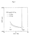
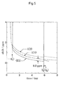
- FIG. 1 illustrates results obtained by measuring, by the NMR, a change in the magnetic field in the magnetic field space with time when a step functional set value is set to the term of the Z0 of the shim at a time (t1), and a square wave value is set thereto at a time (t2) in fact in the superconducting magnet.
- a solid line represents a measured value
- the axis of ordinate represents a value of the magnetic field
- the axis of abscissa represents time.
- the figure shows an appearance that the values of the magnetic field to be originally horizontal between the times (t1) and (t2) largely fluctuate depending on time.
- the set value of the shim is also intermittently changed together with that change-state.
- the change in the probe is frequently conducted, particularly, in the solid-state NMR measurement. That is, there frequently occurs a situation in which new setting is conducted on the shim before a previous magnetic field fluctuation is reduced and disappears, and the magnetic field fluctuation associated with this new setting is overlapped on the previous magnetic field fluctuation.
- a technique called "NMR magnetic field lock" in which deuterated solvent such as deuterated chloroform is used as solvent, and setting of the shim is controlled by the aid of the NMR signal of deuterium, and the above magnetic field fluctuation can be compensated.
- this technique is not used because the sample contains no solvent. In this way, the present invention is mainly intended for the superconducting magnet used for the solid high-resolution NMR measurement.
- the present invention and the NMR magnetic field lock are used together whereby a load on an NMR magnetic field lock function is reduced, and higher-precision measurement is realized. Also, as compensation of the terms other than the Z0, the present invention provides the most effective compensating means.
- the contents of the present invention are mainly described in line with the solid high-resolution NMR measurement, but the application of the present invention is not limited to this case.
- the present invention can be applied to a system that enables shimming using the shim coil for a purpose requiring stabilization of the magnetic field of the superconducting magnet, as represented by a magnetic resonance imaging (MRI).
- MRI magnetic resonance imaging
- various magnetic field modulations are conducted by a modulation coil, and an influence of application of the modulated magnetic field of various arbitrary waveforms on the superconducting magnet can be compensated by the present invention.
- the present invention has been made in view of the above circumstances, and therefore aims at compensating a magnetic field fluctuation caused by mutual interaction between a superconducting coil and a shim coil, and stabilizing a magnetic field in a measurement space in a high-field superconducting magnet.
- the present invention provides a shimming method and a shimming device, which sequentially record a history of conducted shim setting, momentarily dynamically calculate compensation values corresponding to the record by the aid of a characteristic function, and dynamically control the shim coil by the aid of the compensation values thus obtained, to thereby compensate the magnetic field fluctuation of the superconducting magnet which is attributable to the setting of the shim, and stabilize the magnetic field, in an NMR superconducting magnet.
- the shimming method and the shimming device are generically named "shimming system”.
- the setting of the shim is to give a new set value to be set to the shim.
- the setting of the shim transits from a start state to an end state assuming that a state before the setting of the shim is conducted is the start state, and a state based on the setting newly conducted is the end state.
- a curve of an arbitrary waveform connecting the start state and the end state along a time axis is allowed.
- a form or a qualitative aspect of the waveform connecting the start state and the end state is characterized by the type of operation of the shim setting.
- the simplest type of the shim setting operation is a step function linearly connecting the start state and the end state in an infinitely small time.
- the transition process may have a meaning even if the start state and the end state are the same.
- the quantitative aspect of the transition process is characterized by the amount of operation of the setting.
- the type of operation is the step function
- the amount of operation of the setting is equal to a difference in level of the steps, that is, a difference between the start state and the end state.
- the type of operation is a square wave
- the amount of operation of the setting is represented by a height of the square wave and a width on the time axis. In this way, the amount of operation of the setting is not limited to a scalar quantity, but is generally a vector quantity, and expressed by an array.
- the conducted shim setting is characterized by a set value of the shim, the type of operation thereof, and the amount of operation thereof. That is, in the present invention, to sequentially record the history of the conducted shim setting means to record the set value of the conducted shim setting, the type of operation thereof, and the amount of operation thereof in association with times at which they are conducted.
- the time means an absolute value of a time determined according to an appropriate definition on the time axis, and can comply with a general calendar from a viewpoint of the utility. An origin of the time may be arbitrarily determined. Also, in general, a difference between one time and another time is represented by the amount of time, and the amount of time from the origin of the time is represented by the time.
- the time and the amount of time are distinguished according to whether symbol ""' is added, or not, so that the time is t, and the amount of time is t'.
- distinction therebetween is not always essential.
- a shimming device that compensates stability and homogeneity of a magnetic field of a superconducting magnet with a shim coil, in which at least one term of the shim is controlled by the following means (1) to (4).
- the shimming device realizes the following method, and in at least one term of the shim, the set value of the shim is subjected to compensation depending on time by the means configured by the following components (1) to (4).
- the setting of the shim is used solely for adjusting the absolute value and the homogeneity of the magnetic field.
- the setting of the shim designates the end state, and as the type w of operation of the setting, the step function is used.
- the magnetic field modulation is applied to the sample by the magnetic field modulation coil.
- the modulation coil functionally belongs to one type of the shim coils. That is, the application of the magnetic field modulation is one configuration of the setting of the shim, and in the present specification, the setting of the shim includes the magnetic field modulation.
- the start state and the end state of the setting of the shim are identical with each other, and a waveform of the transition process is significant.
- the shape and magnitude of the modulated magnetic field can be designated by the type w and the operation amount s of the setting. It is needless to say that the present invention can be applied to a case in which both of the end state of the shim setting and the transition process are significant.
- the generating compensation function f has the type w of operation of the shim setting as an argument so as to cope with various intended purposes.
- the type of operation of the shim setting is limited to one, for example, if the setting to be conducted is entirely determined as the step function, a dedicated type of operation of the generating compensation function f needs to be prepared, and the record and designation of the type w of operation may be omitted.
- a shimming method in which the generating compensation function and the compensation function are represented by the following respective expressions is implemented.
- This method assumes that the operation amount s is a scalar quantity as represented by a case in which the type of operation of the shim setting is the step function. Since the operation amount s is generally an array, when this method is applied, it is an unspoken understanding to use this method after the array s is converted into the scalar quantity s'.
- the type of operation of the shim setting is the step function
- the operation amount s corresponds to the scalar quantity s' as it is.
- the type of operation is a square wave
- the generating compensation function is normalized and obtained by a specific operation amount s 0 , the generating compensation function can be easily obtained. Also, since the function form is simplified, there is advantageous in that the amount of calculation when calculating the compensation value is reduced. Since the compensation function is indicated by series expansion of the operation amount s on the basis of the generating compensation function, the continuity of the compensation value is automatically ensured. Also, the compensation value can be easily calculated by the small amount of calculation.
- the compensation function is a function that is represented by the series expansion of a relatively low order, and monotonous with respect to the factor, there is no concern that a guaranteed value has an unexpected value with respect to a wide-range input, and a risk that an error occurs in the setting of a guaranteed function to cause a significant failure is removed. That is, wide-area operation can be guaranteed by a small number of operation tests.
- a main portion of the shimming device according to the first and second inventions is installed within a shim coil control device.
- the following respective means is installed in the shim coil control device, and the above shimming method is realized in cooperation with those respective means. That is, the above respective means includes setting receiving means for receiving shim setting, recording means for sequentially recording a history of the setting of the shim, generating compensation function supply means for supplying a predetermined generating compensation function, compensation value calculating means for calculating a compensation value on the basis of the time and the recorded history of the setting of the shim, output value computing means for adding the set value of the shim to the compensation value, and output outgoing means for outputting the computation result to an external.
- the NMR probe device used to obtain the generating compensation function in the shimming device according to the first and second invention, and with the use of this device, the generating compensation function for the terms other than the Z0 can be also easily obtained.
- Each of at least two, desirably seven or more of the plural NMR probe elements includes an NMR measurement coil and a standard sample included therein, and those NMR probe elements are set at given spatially discrete positions, independently. A change of the magnetic field intensity with time at a different place within the measurement space can be measured.
- the shimming device in the NMR measurement using the high-field superconducting magnet, the magnetic field fluctuation before and after the probe change or the shim value adjustment is eliminated to obtain an excellent measurement precision. Also, with the use of the NMR probe device according to the third invention, the correction generating function for the terms other than the Z0 can be efficiently obtained.
- the present invention can be implemented by an electronic computer (computer), a series of computer control codes (program) that controls the operation of the computer, a shim coil driving device that operates through a communication with the computer, and a shim coil that is driven by the shim coil driving device.
- the computer doubles as a computer for control of the NMR measurement, and a necessary program is set up in the computer so as to enable the computer to operate in parallel to the NMR measurement at the same time.
- the computer is set for each of functional parts, and the functions can be dispersed to enhance a fault tolerance and a throughput.
- a device that outputs a signal for controlling the shim coil which is a set including the computer into which the program is installed, a combination thereof, and a peripheral device having a share of that function is called “shim coil control device”.
- a device that controls the stability and the homogeneity of the magnetic field by the shim coil which is a set including the shim coil control device, the shim coil driving device, and the shim coil, is called “shimming device”.
- the shim coil driving device has inputs corresponding to the respective terms of the shim, conducts conversion so as to generate the magnetic field corresponding to the input, and outputs a current to each specific coil within the shim coil.
- the shim coil includes various coil elements wound in diverse directions.
- a conversion expression is generally represented by a tensor. The tensor depends on specific setting of each coil element in the shim coil, and set as the conversion expression inherent to the device within the shim coil driving device in advance. Also, not only the conversion expression but also a specification of wire connection between the shim coil and the shim coil driving device are not generally published, and therefore the shim coil and the shim coil driving device are virtually dealt with as being inextricably linked.
- the shim coil driving device and the shim coil control device are connected to each other by a digital line.
- the shim coil driving device can be so set as to react with only reception of an output from the shim coil control device. Therefore, the system can be configured so that malfunction is not conducted even if the shim coil control device is temporarily separated therefrom.
- a communication procedure between the shim coil control device and the shim coil driving device is not generally published, and the commonalities therebetween are not secured. Therefore, the shim coil driving device and the shim coil control device are virtually inextricably linked.
- the shimming device according to the present invention is realized with the inclusion of the shim coil and the shim coil driving device.
- the present invention is applied to the Z0, thereby improving the measurement precision to obtain a satisfactory result.
- the present invention is desirably applied to the terms sequentially in ascending order (Z1, X1, Y1, XZ, YZ, Z2, X2, Y2 ).
- the probe device to be used When the terms to which the present invention is applied are limited, it is desirable to take the probe device to be used and the symmetry of the sample into account.
- a direction along which the MAS probe device is installed is set so that, for example, an x-axis between the x-axis and a y-axis of the shim coil, and an MAS sample tube are substantially parallel to each other, to thereby enable an influence of the fluctuation in the y-direction to be reduced. Therefore, in the terms other than the Z0, it is desirable that the present invention is applied to Z1, X1, and XZ in the stated order. In this case, if the present invention is applied to those four terms, it is expected to obtain a sufficiently satisfactory result.
- MAS magic angle spinning
- the number of terms (the number of channels) to which the present invention is applied according to a need for the probe device to be used and the required measurement precision.
- the magnetic field in a sample space is composition of a magnetic field generated by the superconducting magnet and a magnetic field generated by the shim coil.
- the magnetic field of the superconducting magnet corresponding to this term is a magnetostatic field B 0 .
- the component of the magnet field along the term of X1 of the shim is described as "B //x1 ", and its value is described as "B 0//x1 +u x1 ".
- the magnetic field components can be resolved into the magnetic field component derived from the superconducting magnet and the magnetic field component derived from the shim coil for description.
- the set value u c of the shim may be described merely as "u” with the omission of C which is an arbitrary index.
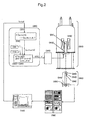
- FIG. 2 is a block diagram illustrating an overall system
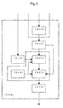
- FIG. 3 is a block diagram of the interior of the shim coil control device.
- a total control computer (100) comprehensively manages any control related to NMR measurement including an NMR measurement device and shim coil control.
- the total control computer (100) receives setting of a shim from an experimenter, and sets a set value of the given shim in a shim coil control device (200).
- the setting of the shim may be given by a computer program instead of the experimenter. For example, in replacement of a probe, the setting of the shim is given an initial setting by a setting file prepared for each probe in advance.
- the shim coil control device (200) takes a core role in the compensation of a shim value in a shimming system according to the present invention.
- the shim coil control device (200) receives setting (u, w, s) of the shim from the total control computer (100), subjects the setting to given compensation, and outputs compensated setting (u') of the shim to a shim coil driving device (300).
- the amount of compensation to be conducted is changed as a function of time.
- the shim coil control device (200) is connected to the total control computer (100) and the shim coil driving device (300) by a digital communication line.
- Shim setting receiving means (220) receives the setting (u, w, s) of the shim from the total control computer (100) through the digital communication line, and delivers the setting to shim setting recording means (230).
- the shim setting recording means (230) receives the setting of the shim from the shim setting receiving means (220).
- the number of times of the received setting of the shim is recorded in a variable N.
- the received setting of the shim is recorded as (u N-1 , w N-1 , s N-1 , t N-1 ) in association with a time t N-1 of that time.
- Generating compensation function supply means supplies diverse predetermined generating compensation functions on demand.
- the generating compensation function is a function of a type w, an operation amount s, and the amount of time t', which is so set as to approximately compensate a magnetic field fluctuation attributable to individual setting.
- the generating compensation function is inherent to the device to be used, and preset from the external prior to the use of the device (dotted line in FIG. 3 ).
- a framework of a function form is described (hard-coded) in a program fashion, and the setting of partial parameters is read from the setting file.
- Compensation value computing means (240) refers to the generating compensation function supply means (210) and the shim setting recording means (230), computes a compensation value at the time t with the use of a compensation function configured by them, and outputs a computation result.
- Symbol " ⁇ ” represents a sum of n (0, 1, 2, ... N-1).
- Output value computing means (250) adds an output of the compensation value computing means (240) to the set value of the shim obtained with reference to the shim setting recording means (230), and outputs the added set value.
- Synchronization signal generating means (260) outputs time information at substantially constant time intervals.
- a computation frequency of the compensation value is rate-controlled according to the output frequency.
- Post-compensation setting output (270) receives the shim setting u' that has been subjected to compensation from the output value computing means (250), and delivers the shim setting u' to the shim coil driving device (300) through the digital communication line. Referring to FIG.
- the shim setting receiving means (220) has a property to operate in synchronism with an external signal since the shim setting receiving means (220) is a part that waits for and receives the setting from the total control computer (100).
- the generating compensation function supply means (210) receives the setting from the external only if the setting is an initial setting at the time of updating the system or the like (a route indicated by a dashed arrow in FIG. 3 ). Since the compensation value computing means (240) is rate-controlled by the synchronization signal generating means (260), as a result of which the output value computing means (250) outputs the compensated setting in synchronism with those means.
- the shim coil driving device (300) drives a shim coil (400) according to the set value received from the shim coil control device (200).
- the shim coil (400) is set integrally with a superconducting magnet (510) to form a high-resolution NMR superconducting magnet device (500) as a whole.
- the measurement space (ES) is set near the center of the magnetic field thereof.
- the high-resolution NMR superconducting magnet device (500) can be equipped with an NMR probe device (600).
- the NMR probe device (600) externally includes a cylindrical housing (610) and a flange part (620), and is attached to the high-resolution NMR superconducting magnet device (500) by the flange part (620).
- a resonator mounting (630) is disposed inside the cylindrical housing (610). Inside the cylindrical housing (610), a resonator is configured by a measurement coil (640) and a tuning circuit (650), which are supported by the resonator mounting (630).
- the measurement coil (640) is located in the center of the magnetic field within a measurement space (ES), and a sample to be measured is held within this coil so that the NMR measurement can be conducted.
- An NMR spectrometer (700) is connected to the NMR probe device (600), irradiates a variety of measurement high frequency pulse trains, and receives an electromagnetic response signal to the irradiated pulse trains, thereby conducting the NMR measurement.
- a sequence of procedures such as the irradiation of the high-frequency pulse trains and the signal reception, which is conducted in the NMR measurement, is called "pulse sequence".
- the operation of the NMR spectrometer (700) is controlled by the total control computer (100).
- the total control computer (100), the shim coil control device (200), the shim coil driving device (300), and the NMR spectrometer (700) autonomously operate while communicating closely with each other. Even if a communication failure occurs among those devices, the operation is continued to the extent possible.
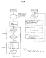
- the respective means implemented within the shim coil control device (200) are realized in more detail by a program represented by a flowchart illustrated in FIG. 4 . Reference numerals corresponding to those in FIG. 3 are added in association with the functions of the respective parts.
- the main functions are realized by a loop within a main program for sequentially recording a change in the given set value of the shim, and a loop within a subprogram for autonomously sequentially outputting the compensation value.
- the main program and the subprogram share global variables, global constants, global functions, and time defined by the main program.
- the subprogram initially starts by the main program, and subsequently, operates out of synchronism with the main program.
- the output of the compensated setting u' is sequentially updated by the subprogram.
- the subprogram can be loaded into the loop of the main program, and conduct synchronous operation.
- the synchronous operation is conducted, there is advantageous in that there is no need to confirm the synchronization at the time of reading or writing a shared variable, and an error hardly occurs in program creation.
- the synchronous operation may be selected taking the above into account.
- the loop of the subprogram is executed at appropriate time intervals according to a synchronization signal supplied from the synchronization signal generating means (260).
- Data such as the global variables, the global constants, or the global functions can be stored in not a volatile main storage such as a semiconductor storage, but a nonvolatile auxiliary storage such as a disc device or a semiconductor nonvolatile storage so as to be shared. In most of cases, this configuration is desirable.
- a volatile main storage such as a semiconductor storage
- a nonvolatile auxiliary storage such as a disc device or a semiconductor nonvolatile storage so as to be shared. In most of cases, this configuration is desirable.
- the interruption can be restored without failure unless the shim coil driving device fails, or a system clock is remarkably wrong. It takes more time to refer to the auxiliary storage than the main storage, but there are frequently no large disadvantages.
- the set value of the shim is set by the total control computer (100) with some means through the digital communication.
- a part of the file system of the shim coil control computer (200) is shared on a computer network by the total control computer (100), and the set value of the shim is set by rewriting the data file set in a shared area. That is, in this embodiment, the setting of the shim is load into the program with the data file on the hard disc device as a medium.
- a procedure of "compensated setting (u') output" in the subprogram is a procedure of setting a compensated set value u' of the shim by the aid of a given communication procedure for the shim coil driving device (300).
- the compensated set value of the shim is transmitted to the shim coil driving device (300), and the shim coil driving device (300) outputs a current converted according to each coil element in response to the compensated set value to drive the shim coil (400).
- the generating compensation function f w (s, t') has a property to approach asymptotically to 0 as the amount of time t' becomes larger. Therefore, for example, when t-t 0 becomes sufficiently large with time, the contribution of f w (s 0 , t-to) can be ignored. It is desirable that such old data is appropriately destroyed.
- timing of updating the compensation value is synchronized with the NMR measurement so as not to affect the measurement.
- a status of executing a pulse sequence of the NMR measurement is monitored, and when data collection for one measurement is completed, and the measurement enters a relaxation wait time, the compensation value may be updated.
- the shim coil control computer 200 monitors the synchronization signal, the sure operation is further expected.
- the generating compensation function f w (s, t') has three arguments of the type w (set), the operation amount s (array or a real number when the second invention is applied), and the amount of time t' (real number), and is defined within the program as a function that returns a value of the real number in advance.
- the set is a set of the types of the operation such as (step function, square wave, triangular wave, saw-tooth wave, ...), and can be associated with subset (0, 1, 2, 3, ...) of integers.
- the number of elements of the set is the number of types of the operation to be dealt with by the system.
- a part of the parameters that define the generating compensation function is set in such a way that it can be read from a definition file on the auxiliary storage.
- a specific expressing method of the generating compensation function f is not limited in principle, and in the respective types w, there can be used a function giving an appropriate approximate value that satisfies a relationship of "
- ⁇ allowable error" for the set (n 0, 1, 2, 7) of the sufficiently extensive and close operation amount and the amount of time (s n , t' n ).
- the compensation value is frequently recalculated at each time t with the use of the generating compensation function, it should be noted that the amount of calculation is prevented from being too large.
- the term of the shim will be described focusing on the term of the Z0 of the shim.
- a value of the magnetic field means a magnetic field intensity when the target is the term of the Z0, and a magnetic gradient along the respective axes when the target is a first-order term (Z1, X1, Y1).
- f w 0 (s 0 , t-t 0 )+p(t)-B 0 -u 0
- the species compensation function may approach asymptotically to the measured value within an error range.
- the positive and negative of sign correspond to parallel and nonparallel to a large magnetostatic field, and a difference occurs between an increase and a decrease in a total energy accumulated in the magnet. Therefore, there are many cases in which the symmetry of that portion is low, to which attention is paid.
- h x ⁇ a k ⁇ x k
- the h(x) is a K-order polynomial expression, and the order K is appropriately set according to a request for the acceptable error or the amount of calculation.
- the generating compensation function for arbitrary (s, t') is obtained by appropriate interpolation with the use of the species compensation function of proximity which is discretely obtained.
- Approximation is not limited to the approximation caused by the above-mentioned linear combination. This problem boils down to a general issue that, on the basis of values that are discretely given on two-dimensional grid points (or lines), functions that are consecutively defined on a two-dimensional plane that approximates those values are obtained. Therefore, diverse approximating methods related to the above problem can be used, and the processing method using a map on the grid can be also used.
- FIG. 5 illustrates the measurement results of the magnetic field fluctuation in the sample space which is measured by the NMR illustrated in FIG. 1 with a change in the origin and the scale from another viewpoint.
- the axis of ordinate represents the magnetic field B in the sample space, the unit is ppm, and the origin on the axis of ordinate is set so that the value when the fluctuation caused by setting the shim recedes approximates to 0.
- a portion indicated by a solid line (E1) corresponds to a value B 0 of the magnetic field when no compensation is conducted.
- B 0 is originally 0.
- B 0 is representative of a finite value due to an influence of the setting of the shim which is conducted immediately before in fact, and this value changes depending on time.
- the compensation function it is expected that the values of B 0 are offset in those sections (t 1 to t 2 , t 3 ).
- the setting (u, w, s, t) of the shim described below are given at the times t 1 , t 2 , and t 3 .
- the following setting at the time t 0 is the setting of a dummy for designating an initial state of the system.
- a curve (E1) corresponds to the above magnetic field p(t).
- the magnitude of a phenomenon associated with relaxation can be expressed by the function of the amount of time t' represented by exp(-t'/ ⁇ ) by using a relaxation time ⁇ characterizing that phenomenon.
- the measurement values cannot be represented by the function. Conceivably, this is because the interaction with the shim coil is different in each position of the superconductor in the superconducting magnet, and also because a plurality of superconductors is used in the superconducting magnet.
- the above relaxation phenomenon can be represented by the following general form as a total of the relaxations with diverse relaxation times ⁇ .
- a m and ⁇ m are fitting parameters, and the order M to be used is appropriately determined taking the acceptable error into account. They depend on the specific configurations of the superconducting magnet and the shim coil.
- the curves illustrated in the figure approximate each other within an error range of 0.01 ppm in the measurement results.
- the following expression specifically represents the obtained generating compensation function (s, t').
- the fluctuation of the magnetic field intensity due to the history of the setting of the shim can be compensated within the error range of 0.01 ppm.
- a specific example of the generating compensation function described above is described for facilitation of deeply understanding the method of obtaining and setting the generating compensation function. It should be noted that the generating compensation function satisfying the conditions is not limited to the above function.
- a short dashed line indicated by (C2) is drawn with the compensation value thus calculated being reversed in a negative sign and shifted up by 0.4 ppm. That is, the curve C2 represents the curve of "-g(t)+0.4ppm".
- the method of this embodiment approximates the sequential change of the setting with small stepwise changes. This is realized by recording a change history of the shim at sufficiently small time intervals when the sequential change is set in the shim. More specifically, this embodiment is implemented in such a manner that when an arbitrary waveform is set, the setting of the waveform is approximated by combining a large number of small stepwise settings, and the stepwise setting of the approximation is continuously given to the method of the first embodiment.
- This embodiment shows an example in which a method of the second invention is applied when the type of operation of the setting is a square wave.
- a value of the operation amount w must be scalar.
- the shim setting of a square wave is conducted between the times (t 2 ) and (t 3 ).
- this pulse is treated as two stepwise changes including the stepwise change at the time (t 2 ) and the stepwise change at the time (t 3 ).
- one pulse combining two changes together can be regarded as one setting of the shim.
- the generating compensation function is defined for the setting of the shim of the pulse shape.
- the above method for representatively indicating the operation amount of the setting of the pulse shape by its area can be applied to not the square pulse but a pulse of an arbitrary waveform. That is, the pulse of the arbitrary waveform is characterized by an area s' which is a value obtained by integrating a height of the waveform with time instead of hxdt in the case of a square.
- the generating compensation function f'(h, dt, t') for the setting of the pulse shape is defined with t'>dt/2 as a domain assuming that the amount of time t' is measured from a center of the pulse.
- the generating compensation function for the step function is f
- f and f' have a relationship represented by the following expression. f ⁇ h dt t ⁇ ⁇ f ⁇ h , t ⁇ + dt / 2 + f ⁇ - h , t ⁇ - dt / 2
- the symbol " ⁇ " indicates that the both sides of this expression equal to each other within the error.
- the generating compensation function f is defined as a function that approximates the measured value as with the generating compensation function f.
- the shimming method according to the present invention can be implemented in the same method with the use of the generating compensation function suitable for the operation of the shim even if the operation of the shim is of the step shape or the arbitrary waveform.
- the operation amount s can be converted into the scalar quantity by integrating the height h of the waveform with the time t to obtain the area s'. Therefore, the method according to the second invention can be applied.
- the operation amount of the setting is not represented by only the size of the waveform, the operation amount is treated as an array, and the generating compensation function corresponding to the array is allocated for treatment.
- the generating compensation function for the term of the Z0 of the shim can be obtained by the normal NMR measurement as described in the first embodiment. Then, a description will be given of the measuring method when obtaining the generating compensation function for the terms other than the Z0 of the shim.
- a first-order term (Z1, X1, Y1) of the shim is a term for correcting the gradient of the magnetic field (intensity of the magnetic field per a unit length) along the respective axes. Therefore, in order to obtain the generating compensation function related to this term, a change of the distribution of the magnetic field within the measurement space with time must be measured.
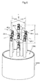
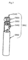
- FIG. 6 illustrates a portion of a resonator neighborhood of the NMR probe device having seven probe elements within the measurement space as an example of the probe device according to the fourth invention.
- a portion below a resonator mounting (630b) of a cylindrical housing (610b) is omitted.
- each NMR probe element (800) includes a measurement coil (810), a standard sample (820) disposed within the measurement coil (810), a tuning capacitor (830) connected in parallel to the measurement coil (810), and used for mainly adjusting a resonance frequency, a matching capacitor (840) inserted between the measurement coil (810) and a transmission line, and used for mainly adjusting impedance matching, and a coaxial cable (850) performing a transmission line of a measurement high-frequency signal.
- the respective parts are connected to each other by brazing.
- a resonator is configured by the measurement coil (810) and the tuning capacitor (830). All of those parts are made of nonmagnetic material so as not to affect the NMR measurement.
- the nonmagnetic property is not at least a ferromagnetic property, and has no large value of paramagnetic susceptibility and the like.
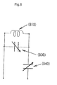
- FIG. 8 An electric equivalent circuit of the resonator neighborhood in the NMR probe element (800) is illustrated in FIG. 8 .
- the respective capacitors of the tuning capacitor (830) and the matching capacitor (840) are configured by appropriately connecting a variable capacitor and a fixed-capacitance capacitor in parallel or in series, and have a certain degree of variable range.
- the NMR probe element (800) only needs to obtain the lowest NMR signal. For that reason, a withstand voltage of the capacitors does not require that of the normal NMR probe. Therefore, a small-sized chip part can be used.
- the measurement coil (810) can be supported by the coaxial cable (850).
- the coaxial cable (850) is fixed to the resonator mounting (630b).
- a position of the resonator is shown with the center of the measurement coil as a reference point.
- the respective resonators are symmetrically arranged on the origin, and the respective axes of the X-axis, the Y-axis, and the Z-axis, and denoted by symbols (R00), (RX-), (RX+), (RY-), (RY+), (RZ-), and (RZ+).
- a distance between the resonator (RX-) and the resonator (RX+) is denoted by (LX)
- a distance between the resonator (RY-) and the resonator (RY+) is denoted by (LY)
- a distance between the resonator (RZ-) and the resonator (RZ+) is denoted by (LZ).
- any standard samples are available if an NMR signal with some degree of sharpness is obtained.
- deuterium water (D 2 O) in which hydrogen atoms (H) in water (H 2 O) are replaced with deuterium atoms (D) is an optimum sample because treatment is easy, and the resonance frequency is reasonable.
- the resonance frequency of the NMR of diplon is about 143 MHz.
- the resonator is configured by a coil and a capacitor, a size of the resonator is sufficiently small as compared with the wavelength, and a so-called lumped parameter circuit treatment is efficient. This results in such advantages that the design and adjustment of the resonator are easy.
- a selective switch switch
- the measurement frequency is lower.
- deuterium water is used as the standard sample.
- the deuterium water is sealed in a resin tube by melting the resin.
- a method of sealing the sample in the tube is not limited to melting of the resin, but can be conducted by resin of a rubber closure or adhesive.
- a deuterated solvent such as deuterated chloroform is also similarly available. However, because the deuterated solvent is low in boiling point, there is a difficulty in requiring a technique for sealing in the tube.
- a resonance frequency F E at that position is obtained.
- the DF x corresponds to the term X1 of the shim.
- a probe element (R00) located in the center (origin) of the magnetic field can be used not only for obtaining the generating compensation function for the term of the Z0, but also for verification of the measured value of the higher-order term.
- the magnetic field of the origin would not fluctuate. If the magnetic field of the origin largely fluctuates, there is a high possibility that a positional relationship of the superconducting magnet, the shim coil, and the probe, or the setting of a conversion expression within the shim coil driving device is displaced. Therefore, the displacement of the setting should be corrected.
- the probe elements are appropriately arranged in an unoccupied space so as to perform both of the normal measurement and the magnetic gradient measurement.
- a selector switch using a high-frequency relay can be inserted between the probe and the NMR spectrometer. Further, selection of the probe elements is designated during a pulse sequence, and on the basis of the designation, the selector switch can be controlled. With this configuration, a plurality of the probe elements can conduct the measurement in parallel by time sharing, thereby remarkably reducing the measurement time.
Landscapes
- Physics & Mathematics (AREA)
- Condensed Matter Physics & Semiconductors (AREA)
- General Physics & Mathematics (AREA)
- Electromagnetism (AREA)
- Magnetic Resonance Imaging Apparatus (AREA)
Abstract
Description
- The present invention relates to a technology for obtaining a magnetic field space large in homogeneity and high in stability, which is required when measuring a nuclear magnetic resonance (NMR) with high precision in a magnetic field of a superconducting magnet.
- The superconducting magnet has been generally known as a magnet that can generate a homogenous and stable magnetic field (magnetostatic field). However, the homogeneity and stability of the magnetic field do not satisfy precision required for high-resolution NMR measurement with no change. As known in
Non-Patent Document 1, in the high-resolution NMR measurement, there is required that a turbulence of the magnetostatic field is 0.01 ppm or lower within a space of 1 cm3 as a typical example, although depending on a need for measurement precision. Also, there is required that a change in the magnetostatic field with time is 0.01 ppm or lower per one hour. As a unit representative of a magnitude of the magnetic field, a ratio (ppm = 1/1000000) of that magnitude to a magnitude of the magnetostatic field developed by the superconducting magnet is frequently used. - For that reason, in the superconducting magnet for the NMR, as known in
Patent Document 1, the magnetic field intensity and the magnetic field homogeneity are corrected by the aid of a shim coil integral with the superconducting magnet. Setting its operating conditions to the shim coil is called "setting of the shim", and various parameters set in the shim are called "terms of the shim". The terms of the shim includes a Z0 (correction of a magnetic field value in parallel to a magnetostatic field), a Z1 (linear function correction of a magnetic gradient in parallel to the magnetostatic field), an X1 (linear function correction of the magnetic gradient in a direction perpendicular to the magnetostatic field), and a Y1 (linear function correction of the magnetic gradient in a direction perpendicular to the magnetostatic field and the X1) in correspondence with the magnetic field value to be corrected, a direction of the magnetic gradient, or a function form. That is, the term of the shim represents the correction magnetic field in a measurement space by its direction (X, Y, Z, XZ, YZ, ...), and the order (0, 1, 2, ...) of approximate in that direction. - The number and type of terms of the settable shim are determined depending on a device to be used. Also, in general, the set value of the shim means an array (Z0 Z1, Z2, Z3, X1, Y1, XZ, YZ, ...) in which the terms of the settable shim are combined together.
In this way, in the superconducting magnet for the NMR, an absolute value (term of zero order) of the magnetic field and various unhomogeneity (term of first order or higher) are generally corrected by the aid of the shim coil. To control the stability and homogeneity of the magnetic field by the shim coil is called "shimming". - The magnetic field formed by the shim coil interacts with a superconducting coil, and the magnetic field in the measurement space intricately fluctuates depending on time in correspondence with a history of values of the magnetic field generated by the shim coil. For example, when the set value of the shim is changed with a change in a probe, a long time of one week or longer may be required until the magnetic field of the superconducting magnet is stabilized.
This phenomenon is remarkably observed in the superconducting magnets for a high-field NMR, particularly, the superconducting magnet for a solid-state NMR (1 H-930 MHz=21.8T) that generates the world-class magnetic field which is developed and used by us among those superconducting magnets, and adversely affects the NMR measurement.FIG. 1 illustrates results obtained by measuring, by the NMR, a change in the magnetic field in the magnetic field space with time when a step functional set value is set to the term of the Z0 of the shim at a time (t1), and a square wave value is set thereto at a time (t2) in fact in the superconducting magnet. In the figure, a solid line represents a measured value, the axis of ordinate represents a value of the magnetic field, and the axis of abscissa represents time. The figure shows an appearance that the values of the magnetic field to be originally horizontal between the times (t1) and (t2) largely fluctuate depending on time. - In the NMR measurement, since the probe is changed for each of measurement nuclides, the set value of the shim is also intermittently changed together with that change-state. The change in the probe is frequently conducted, particularly, in the solid-state NMR measurement. That is, there frequently occurs a situation in which new setting is conducted on the shim before a previous magnetic field fluctuation is reduced and disappears, and the magnetic field fluctuation associated with this new setting is overlapped on the previous magnetic field fluctuation.
- It is assumed that a principle for generating the magnetic field fluctuation occurs because it takes time for a magnetic flux generated by the shim coil to migrate within the superconductor of the magnet while repeating pinning operation and hopping operation. When a non-equilibrium state of the distribution of the magnetic flux is reduced into an equilibrium state, the migration of the magnetic flux is terminated, and the magnetic field is stabilized. The magnitude of this effect depends on the property of the used superconductor, and is more remarkable as the magnetic field of the magnet is stronger. However, in principle, it is conceivable that the same effects occur to various degrees in the superconducting magnet that generates the intense magnetic field by the aid of type II superconductor. It is expected that a countermeasure against this phenomenon becomes an essential technology as the magnetic field of the NMR becomes further stronger.
- In a solution NMR measurement in which a measurement target is a solution sample, there is generally used a technique called "NMR magnetic field lock" in which deuterated solvent such as deuterated chloroform is used as solvent, and setting of the shim is controlled by the aid of the NMR signal of deuterium, and the above magnetic field fluctuation can be compensated. However, in a solid-state NMR measurement in which a measurement target is solid, this technique is not used because the sample contains no solvent. In this way, the present invention is mainly intended for the superconducting magnet used for the solid high-resolution NMR measurement. Even in the solution NMR measurement, the present invention and the NMR magnetic field lock are used together whereby a load on an NMR magnetic field lock function is reduced, and higher-precision measurement is realized. Also, as compensation of the terms other than the Z0, the present invention provides the most effective compensating means.
- In the present specification, the contents of the present invention are mainly described in line with the solid high-resolution NMR measurement, but the application of the present invention is not limited to this case.
The present invention can be applied to a system that enables shimming using the shim coil for a purpose requiring stabilization of the magnetic field of the superconducting magnet, as represented by a magnetic resonance imaging (MRI). In the MRI, various magnetic field modulations are conducted by a modulation coil, and an influence of application of the modulated magnetic field of various arbitrary waveforms on the superconducting magnet can be compensated by the present invention.
Also, in the solution NMR measurement, when an experiment (gradient shim method) in which a gradient magnetic field is applied by the aid of a gradient magnetic field shim coil is conducted, an influence of the application of the intermittent gradient magnetic field on the superconducting magnet can be compensated by application of the present invention. - The present invention has been made in view of the above circumstances, and therefore aims at compensating a magnetic field fluctuation caused by mutual interaction between a superconducting coil and a shim coil, and stabilizing a magnetic field in a measurement space in a high-field superconducting magnet.
- The present invention provides a shimming method and a shimming device, which sequentially record a history of conducted shim setting, momentarily dynamically calculate compensation values corresponding to the record by the aid of a characteristic function, and dynamically control the shim coil by the aid of the compensation values thus obtained, to thereby compensate the magnetic field fluctuation of the superconducting magnet which is attributable to the setting of the shim, and stabilize the magnetic field, in an NMR superconducting magnet. The shimming method and the shimming device are generically named "shimming system".
- The setting of the shim is to give a new set value to be set to the shim. When the setting of the shim is conducted, the setting of the shim transits from a start state to an end state assuming that a state before the setting of the shim is conducted is the start state, and a state based on the setting newly conducted is the end state. In a process of transition from the start state to the end state, a curve of an arbitrary waveform connecting the start state and the end state along a time axis is allowed. A form or a qualitative aspect of the waveform connecting the start state and the end state is characterized by the type of operation of the shim setting.
- The simplest type of the shim setting operation is a step function linearly connecting the start state and the end state in an infinitely small time. Depending on the type of operation, the transition process may have a meaning even if the start state and the end state are the same. The quantitative aspect of the transition process is characterized by the amount of operation of the setting. When the type of operation is the step function, the amount of operation of the setting is equal to a difference in level of the steps, that is, a difference between the start state and the end state. When the type of operation is a square wave, the amount of operation of the setting is represented by a height of the square wave and a width on the time axis. In this way, the amount of operation of the setting is not limited to a scalar quantity, but is generally a vector quantity, and expressed by an array.
- The conducted shim setting is characterized by a set value of the shim, the type of operation thereof, and the amount of operation thereof. That is, in the present invention, to sequentially record the history of the conducted shim setting means to record the set value of the conducted shim setting, the type of operation thereof, and the amount of operation thereof in association with times at which they are conducted. The time means an absolute value of a time determined according to an appropriate definition on the time axis, and can comply with a general calendar from a viewpoint of the utility. An origin of the time may be arbitrarily determined. Also, in general, a difference between one time and another time is represented by the amount of time, and the amount of time from the origin of the time is represented by the time. In the present specification, the time and the amount of time are distinguished according to whether symbol ""' is added, or not, so that the time is t, and the amount of time is t'. However, if a physical interruption is not incorrect, distinction therebetween is not always essential.
- According to the first invention, there is provided a shimming device that compensates stability and homogeneity of a magnetic field of a superconducting magnet with a shim coil, in which at least one term of the shim is controlled by the following means (1) to (4).
- (1) shim setting recording means that records, when the setting of the shim is conducted, a set value u of the shim, a type w of set operation, operation amount s of setting, and the time t of setting, by associating the setting finally conducted with an index N-1 so as to be referred to as (wn, un, sn, tn) by the aid of an index n which is a value of 0 to N-1 where the number of times of setting is N;
- (2) generating compensation function supply means that supplies a generating compensation function "fw(s,t')" that is a function having the type w of the operation, the operation amount s, and the amount of time t' as factors, which has a property to become 0 when the amount of time t' is infinite, and is set so as to approximately compensate a magnetic field fluctuation attributable to individual setting;
- (3) compensation value calculating means that calculates a compensation value at the time t by the aid of a compensation function assuming that symbol "Σ" represents a sum of n (0, 1, 2, ... N-1), and the compensation function "g(t)" is a function of the time t which is expressed as "g(t)=Σfwn(sn, t-tn)" by the generating compensation function and the setting of the shim conducted before the time t; and
- (4) shim coil driving means that drives the shim coil by the aid of a sum of the compensation value obtained by the compensation value calculating means, and a latest set value uN-1.
- The shimming device according to the first invention realizes the following method, and in at least one term of the shim, the set value of the shim is subjected to compensation depending on time by the means configured by the following components (1) to (4).
- (1) When the setting of the shim is conducted, the number of times N of conducted setting, the set value u (generally, a real number) of the shim, the type w (generally, set) of operation thereof, the operation amount s thereof (generally, array having elements of real numbers), and the time t (generally, a real number) at that time are sequentially recorded. It is desirable that those values are generally recorded as the array (un, wn, sn, tn). Here, n is an index of an integer for distinguishing the individual setting, and a range of n is (0, 1, 2, ... N-1). In this case, the latest record is designated by an index N-1.
- (2) The generating compensation function fw(s, t') is a function of the type w, the operation amount s, and the amount of time t' (generally, a real number), and obtained and set in advance as a function representing the compensation amount (generally, real number) for individual setting. The generating compensation function f is a function having a property to become 0 when t' is infinite.
- (3) The compensation value (generally, a real number) at the time t is calculated by the aid of the compensation function g(t)=Σfwn(sn, t-tn) which is a function of the time t. Symbol Σ represents a sum of n (0, 1, 2, ... N-1). The compensation function g(t) is expressed by the generating compensation function f and the record (wn, sn, tn) of the shim setting. The compensation value at the time t is momentarily obtained by substituting the time t into the compensation function g(t).
- (4) The compensated value u' (generally, a real number) is obtained as a sum of the latest set value and the compensation value by Expression "u'=uN-1+g(t)". The shim coil is driven by using the compensated value u'.
- In most of the general NMR measurement, the setting of the shim is used solely for adjusting the absolute value and the homogeneity of the magnetic field. In this case, it is significant that the setting of the shim designates the end state, and as the type w of operation of the setting, the step function is used.
On the other hand, when the gradient magnetic field method is used in the NMR measurement, or the MRI measurement is conducted, it is significant that the magnetic field modulation is applied to the sample by the magnetic field modulation coil. The modulation coil functionally belongs to one type of the shim coils. That is, the application of the magnetic field modulation is one configuration of the setting of the shim, and in the present specification, the setting of the shim includes the magnetic field modulation. In this case, generally, the start state and the end state of the setting of the shim are identical with each other, and a waveform of the transition process is significant. The shape and magnitude of the modulated magnetic field can be designated by the type w and the operation amount s of the setting.
It is needless to say that the present invention can be applied to a case in which both of the end state of the shim setting and the transition process are significant.
In this way, in the present invention, the generating compensation function f has the type w of operation of the shim setting as an argument so as to cope with various intended purposes.
If the type of operation of the shim setting is limited to one, for example, if the setting to be conducted is entirely determined as the step function, a dedicated type of operation of the generating compensation function f needs to be prepared, and the record and designation of the type w of operation may be omitted. - According to the second invention, in the shimming device of the first invention, a shimming method in which the generating compensation function and the compensation function are represented by the following respective expressions is implemented.


(where symbol Σ represents a sum of n (0, 1, 2, ... N-1)).
where

Symbol s0 is a constant used for normalization.
Ak, α, and β represent respective appropriate constants (fitting parameters) for approximation. - This method (second invention) assumes that the operation amount s is a scalar quantity as represented by a case in which the type of operation of the shim setting is the step function. Since the operation amount s is generally an array, when this method is applied, it is an unspoken understanding to use this method after the array s is converted into the scalar quantity s'. When the type of operation of the shim setting is the step function, since the number of elements of the operation amount s is one, the operation amount s corresponds to the scalar quantity s' as it is. Also, for example, when the type of operation is a square wave, the elements of s are two elements of a height h and a width dt. Therefore, with the use of those elements, an area s' obtained as s'=hxdt can be used as the scalar quantity.
- In this method (second invention), since the generating compensation function is normalized and obtained by a specific operation amount s0, the generating compensation function can be easily obtained. Also, since the function form is simplified, there is advantageous in that the amount of calculation when calculating the compensation value is reduced.
Since the compensation function is indicated by series expansion of the operation amount s on the basis of the generating compensation function, the continuity of the compensation value is automatically ensured. Also, the compensation value can be easily calculated by the small amount of calculation.
In particular, if the compensation function is a function that is represented by the series expansion of a relatively low order, and monotonous with respect to the factor, there is no concern that a guaranteed value has an unexpected value with respect to a wide-range input, and a risk that an error occurs in the setting of a guaranteed function to cause a significant failure is removed. That is, wide-area operation can be guaranteed by a small number of operation tests. - A main portion of the shimming device according to the first and second inventions is installed within a shim coil control device. The following respective means is installed in the shim coil control device, and the above shimming method is realized in cooperation with those respective means.
That is, the above respective means includes setting receiving means for receiving shim setting, recording means for sequentially recording a history of the setting of the shim, generating compensation function supply means for supplying a predetermined generating compensation function, compensation value calculating means for calculating a compensation value on the basis of the time and the recorded history of the setting of the shim, output value computing means for adding the set value of the shim to the compensation value, and output outgoing means for outputting the computation result to an external. - According to the third invention, there is provided the NMR probe device used to obtain the generating compensation function in the shimming device according to the first and second invention, and with the use of this device, the generating compensation function for the terms other than the Z0 can be also easily obtained. Each of at least two, desirably seven or more of the plural NMR probe elements includes an NMR measurement coil and a standard sample included therein, and those NMR probe elements are set at given spatially discrete positions, independently. A change of the magnetic field intensity with time at a different place within the measurement space can be measured.
- With the use of the shimming device according to the first and second inventions, in the NMR measurement using the high-field superconducting magnet, the magnetic field fluctuation before and after the probe change or the shim value adjustment is eliminated to obtain an excellent measurement precision.
Also, with the use of the NMR probe device according to the third invention, the correction generating function for the terms other than the Z0 can be efficiently obtained. -
-
FIG. 1 is a graph illustrating a measured value and approximate curves of a magnetic field fluctuation of a superconducting magnet. -
FIG. 2 is a block diagram illustrating a system configuration according to a first embodiment. -
FIG. 3 is a block diagram illustrating an internal configuration of a shim coil control device. -
FIG. 4 is a flowchart illustrating the operation of the shim coil control device. -
FIG. 5 is a graph illustrating a measured value and approximate curves of the magnetic field fluctuation of the superconducting magnet. -
FIG. 6 is a perspective view illustrating a resonator neighborhood of an NMR probe device according to a fifth embodiment. -
FIG. 7 is a perspective view illustrating the NMR probe element according to the fifth embodiment. -
FIG. 8 is a circuit illustrating an equivalent circuit of the NMR probe element according to the fifth embodiment. - Symbols in the figures represent the following elements.
- (t1), (t2), (t3): times
- (E1): curve of magnetic field
- (C1), (C2): approximate curve
- (ES): measurement space
- (ROO), (RX-), (RX+), (RY-), (RY+), (RZ-), (RZ+): measurement coil
- (LX), (LY), (LZ): distance between measurement coils
- X: X-axis
- Y: Y-axis
- Z: Z-axis
- (100): total control computer
- (200): shim coil control device
- (210): generating compensation function supply means
- (220): shim setting receiving means
- (230): shim setting recording means
- (240): compensation value computing means
- (250): output value computing means
- (260): synchronization signal generating means
- (270): post-compensation setting output means
- (300): shim coil driving device
- (400): shim coil
- (500): high-resolution NMR superconducting magnet device
- (510): superconducting magnet
- (600): NMR probe device
- (610), (610b): cylindrical housing
- (620): flange
- (630), (630b): resonator mounting
- (640): measurement coil
- (650): tuning circuit
- (700): NMR spectrometer
- (800): NMR probe element
- (810): measurement coil
- (820): standard sample
- (830): tuning capacitor
- (840): matching capacitor
- (850): coaxial cable
- The present invention can be implemented by an electronic computer (computer), a series of computer control codes (program) that controls the operation of the computer, a shim coil driving device that operates through a communication with the computer, and a shim coil that is driven by the shim coil driving device. The computer doubles as a computer for control of the NMR measurement, and a necessary program is set up in the computer so as to enable the computer to operate in parallel to the NMR measurement at the same time. Also, the computer is set for each of functional parts, and the functions can be dispersed to enhance a fault tolerance and a throughput.
In the present specification, a device that outputs a signal for controlling the shim coil, which is a set including the computer into which the program is installed, a combination thereof, and a peripheral device having a share of that function is called "shim coil control device". Also, a device that controls the stability and the homogeneity of the magnetic field by the shim coil, which is a set including the shim coil control device, the shim coil driving device, and the shim coil, is called "shimming device". - The shim coil driving device has inputs corresponding to the respective terms of the shim, conducts conversion so as to generate the magnetic field corresponding to the input, and outputs a current to each specific coil within the shim coil. The shim coil includes various coil elements wound in diverse directions. A conversion expression is generally represented by a tensor. The tensor depends on specific setting of each coil element in the shim coil, and set as the conversion expression inherent to the device within the shim coil driving device in advance. Also, not only the conversion expression but also a specification of wire connection between the shim coil and the shim coil driving device are not generally published, and therefore the shim coil and the shim coil driving device are virtually dealt with as being inextricably linked.
- In many cases, the shim coil driving device and the shim coil control device are connected to each other by a digital line. When the shim coil driving device and the shim coil control device are connected by the digital line, the shim coil driving device can be so set as to react with only reception of an output from the shim coil control device. Therefore, the system can be configured so that malfunction is not conducted even if the shim coil control device is temporarily separated therefrom.
A communication procedure between the shim coil control device and the shim coil driving device is not generally published, and the commonalities therebetween are not secured. Therefore, the shim coil driving device and the shim coil control device are virtually inextricably linked.
In implementation of the present invention, a variety of known techniques and existing devices can be employed in the shim coil and the shim coil driving device. However, for the above reasons, the shim coil and the shim coil driving device are inextricably linked in implementation of the present invention, and therefore, the shimming device according to the present invention is realized with the inclusion of the shim coil and the shim coil driving device. - The fluctuation corresponding to the term of the Z0 most affects precision in the NMR measurement. Therefore, in many cases, the present invention is applied to the Z0, thereby improving the measurement precision to obtain a satisfactory result. When more precise compensation is required, the present invention is desirably applied to the terms sequentially in ascending order (Z1, X1, Y1, XZ, YZ, Z2, X2, Y2 ...).
- When the terms to which the present invention is applied are limited, it is desirable to take the probe device to be used and the symmetry of the sample into account. For example, when a magic angle spinning (MAS) probe device is used in solid-state NMR measurement, a direction along which the MAS probe device is installed is set so that, for example, an x-axis between the x-axis and a y-axis of the shim coil, and an MAS sample tube are substantially parallel to each other, to thereby enable an influence of the fluctuation in the y-direction to be reduced. Therefore, in the terms other than the Z0, it is desirable that the present invention is applied to Z1, X1, and XZ in the stated order. In this case, if the present invention is applied to those four terms, it is expected to obtain a sufficiently satisfactory result.
- In this way, it is preferable to set the number of terms (the number of channels) to which the present invention is applied according to a need for the probe device to be used and the required measurement precision.
- The magnetic field in a sample space is composition of a magnetic field generated by the superconducting magnet and a magnetic field generated by the shim coil. For example, when attention is paid to the term of the Z0 of the shim, the magnetic field of the superconducting magnet corresponding to this term is a magnetostatic field B0. In this case, a magnetic field B in the sample space becomes a sum of the magnetic field B0 generated by the superconducting magnet and a magnetic field uz0 generated by the shim coil. That is, "B=B0+uz0" is met.
In the terms other than the Z0 of the shim, an unhomogeneous component of the magnetic field corresponding to a term C (C=Z1, X1, Y1 ...) of the shim is described as "B//c". Also, a magnetic field component corresponding to the term C of the shim derived from the superconducting magnet is described as "B0//c", and a magnetic field component corresponding to the term C of the shim which is developed by the shim coil is described as "uc". That is, the components of the magnetic field in the respective directions in the sample space are described as "B//c=B0//c+uc" (C=Z1, X1, Y1 ...). For example, the component of the magnet field along the term of X1 of the shim is described as "B//x1", and its value is described as "B0//x1+ux1". Thus, the magnetic field components can be resolved into the magnetic field component derived from the superconducting magnet and the magnetic field component derived from the shim coil for description.
Further, B//z0=B and B0//z0=B0 are defined. As a result, the respective components of the magnetic field in the sample space are uniformly described as "B//c=B0//c+uc" (C=Z0, Z1, X1, Y1 ...).
When discussion is focused on one arbitrary term of the shim, the set value uc of the shim may be described merely as "u" with the omission of C which is an arbitrary index. - In the following description, if not particularly described, attention is paid to one term of the shim in the description. The Z0 and the other terms (Z1, X1, Y1, ...) are different in only the configuration of an appropriate measurement device when obtaining the generating correction function, and the present invention can be similarly applied to the other configurations thereof in principle.
Hereinafter, a description will be given in more detail of the contents of the present invention with reference to the illustrations of specific embodiments. - First, a specific device configuration according to this embodiment will be described with reference to
FIGS. 2 and3 .FIG. 2 is a block diagram illustrating an overall system, andFIG. 3 is a block diagram of the interior of the shim coil control device.
A total control computer (100) comprehensively manages any control related to NMR measurement including an NMR measurement device and shim coil control. The total control computer (100) receives setting of a shim from an experimenter, and sets a set value of the given shim in a shim coil control device (200). The setting of the shim may be given by a computer program instead of the experimenter. For example, in replacement of a probe, the setting of the shim is given an initial setting by a setting file prepared for each probe in advance. - The shim coil control device (200) takes a core role in the compensation of a shim value in a shimming system according to the present invention. The shim coil control device (200) receives setting (u, w, s) of the shim from the total control computer (100), subjects the setting to given compensation, and outputs compensated setting (u') of the shim to a shim coil driving device (300). The amount of compensation to be conducted is changed as a function of time. The shim coil control device (200) is connected to the total control computer (100) and the shim coil driving device (300) by a digital communication line.
- The following respective means are installed within the shim coil control device (200), and those respective means operate in cooperation with each other to conduct given operation as a while.
Shim setting receiving means (220) receives the setting (u, w, s) of the shim from the total control computer (100) through the digital communication line, and delivers the setting to shim setting recording means (230).
The shim setting recording means (230) receives the setting of the shim from the shim setting receiving means (220). The number of times of the received setting of the shim is recorded in a variable N. The received setting of the shim is recorded as (uN-1, wN-1, sN-1, tN-1) in association with a time tN-1 of that time. The recorded setting (un, wn, sn, tn) (n=0, 1, 2, ... N-1) of the shim and the number of times N of conducted setting can be referred to from other means. - Generating compensation function supply means (210) supplies diverse predetermined generating compensation functions on demand. The generating compensation function is a function of a type w, an operation amount s, and the amount of time t', which is so set as to approximately compensate a magnetic field fluctuation attributable to individual setting. The generating compensation function is inherent to the device to be used, and preset from the external prior to the use of the device (dotted line in
FIG. 3 ). A framework of a function form is described (hard-coded) in a program fashion, and the setting of partial parameters is read from the setting file. - Compensation value computing means (240) refers to the generating compensation function supply means (210) and the shim setting recording means (230), computes a compensation value at the time t with the use of a compensation function configured by them, and outputs a computation result. A compensation function "g(t)" is a function of the time t which is expressed as "g(t)=Σfwn(sn, t-tn)" by the generating compensation function and the setting of the shim conducted before the time t. Symbol "Σ" represents a sum of n (0, 1, 2, ... N-1).
Output value computing means (250) adds an output of the compensation value computing means (240) to the set value of the shim obtained with reference to the shim setting recording means (230), and outputs the added set value. A compensated set value u' can be obtained by using a formula "u'=uN-1+g(t)".
Synchronization signal generating means (260) outputs time information at substantially constant time intervals. A computation frequency of the compensation value is rate-controlled according to the output frequency.
Post-compensation setting output (270) receives the shim setting u' that has been subjected to compensation from the output value computing means (250), and delivers the shim setting u' to the shim coil driving device (300) through the digital communication line.
Referring toFIG. 3 , a flow of information is indicated by arrows, and the strength of joint of the respective means is indicated by enclosures of dotted lines. For example, the shim setting receiving means (220) has a property to operate in synchronism with an external signal since the shim setting receiving means (220) is a part that waits for and receives the setting from the total control computer (100).
The generating compensation function supply means (210) receives the setting from the external only if the setting is an initial setting at the time of updating the system or the like (a route indicated by a dashed arrow inFIG. 3 ).
Since the compensation value computing means (240) is rate-controlled by the synchronization signal generating means (260), as a result of which the output value computing means (250) outputs the compensated setting in synchronism with those means. - The shim coil driving device (300) drives a shim coil (400) according to the set value received from the shim coil control device (200). The shim coil (400) is set integrally with a superconducting magnet (510) to form a high-resolution NMR superconducting magnet device (500) as a whole. The measurement space (ES) is set near the center of the magnetic field thereof.
- The high-resolution NMR superconducting magnet device (500) can be equipped with an NMR probe device (600). The NMR probe device (600) externally includes a cylindrical housing (610) and a flange part (620), and is attached to the high-resolution NMR superconducting magnet device (500) by the flange part (620). A resonator mounting (630) is disposed inside the cylindrical housing (610). Inside the cylindrical housing (610), a resonator is configured by a measurement coil (640) and a tuning circuit (650), which are supported by the resonator mounting (630). The measurement coil (640) is located in the center of the magnetic field within a measurement space (ES), and a sample to be measured is held within this coil so that the NMR measurement can be conducted.
- An NMR spectrometer (700) is connected to the NMR probe device (600), irradiates a variety of measurement high frequency pulse trains, and receives an electromagnetic response signal to the irradiated pulse trains, thereby conducting the NMR measurement. A sequence of procedures such as the irradiation of the high-frequency pulse trains and the signal reception, which is conducted in the NMR measurement, is called "pulse sequence". The operation of the NMR spectrometer (700) is controlled by the total control computer (100).
The total control computer (100), the shim coil control device (200), the shim coil driving device (300), and the NMR spectrometer (700) autonomously operate while communicating closely with each other. Even if a communication failure occurs among those devices, the operation is continued to the extent possible. - The respective means implemented within the shim coil control device (200) are realized in more detail by a program represented by a flowchart illustrated in
FIG. 4 . Reference numerals corresponding to those inFIG. 3 are added in association with the functions of the respective parts. As illustrated inFIG. 4 , the main functions are realized by a loop within a main program for sequentially recording a change in the given set value of the shim, and a loop within a subprogram for autonomously sequentially outputting the compensation value. The main program and the subprogram share global variables, global constants, global functions, and time defined by the main program. The subprogram initially starts by the main program, and subsequently, operates out of synchronism with the main program. The output of the compensated setting u' is sequentially updated by the subprogram. - The subprogram can be loaded into the loop of the main program, and conduct synchronous operation. When the synchronous operation is conducted, there is advantageous in that there is no need to confirm the synchronization at the time of reading or writing a shared variable, and an error hardly occurs in program creation. On the other hand, there is a possibility that a delay of the setting process extends over the output, and timing of the output is not stabilized. Therefore, the synchronous operation may be selected taking the above into account.
- Although not particularly illustrated in
FIG. 4 , for the purpose of reducing a load on the device, the loop of the subprogram is executed at appropriate time intervals according to a synchronization signal supplied from the synchronization signal generating means (260). - Data such as the global variables, the global constants, or the global functions can be stored in not a volatile main storage such as a semiconductor storage, but a nonvolatile auxiliary storage such as a disc device or a semiconductor nonvolatile storage so as to be shared. In most of cases, this configuration is desirable. When data is stored in the nonvolatile auxiliary storage, even if the system is abruptly interrupted, the interruption can be restored without failure unless the shim coil driving device fails, or a system clock is remarkably wrong. It takes more time to refer to the auxiliary storage than the main storage, but there are frequently no large disadvantages. It is further desirable that storage of the information is appropriately multiplexed by using both of the main storage and the auxiliary storage to provide for the abrupt interruption of the system while ensuring a reference speed.
In this embodiment, those data is stored as a data file on a file system configured in a hard disc device so as to be shared, and the respective programs are synchronized with the data on the main storage by monitoring an update status of their files.
In this embodiment, in more detail, a data set including an integer variable N, and the array variable (un, wn, sn, tn) having (N-1) elements (n=0, 1, 2, ... N-1), which are the global variable, are shared between the main program and the subprogram with the data file as a medium. - The set value of the shim is set by the total control computer (100) with some means through the digital communication. In this embodiment, a part of the file system of the shim coil control computer (200) is shared on a computer network by the total control computer (100), and the set value of the shim is set by rewriting the data file set in a shared area. That is, in this embodiment, the setting of the shim is load into the program with the data file on the hard disc device as a medium.
- A procedure of "compensated setting (u') output" in the subprogram is a procedure of setting a compensated set value u' of the shim by the aid of a given communication procedure for the shim coil driving device (300). With this procedure, the compensated set value of the shim is transmitted to the shim coil driving device (300), and the shim coil driving device (300) outputs a current converted according to each coil element in response to the compensated set value to drive the shim coil (400).
- The generating compensation function fw(s, t') has a property to approach asymptotically to 0 as the amount of time t' becomes larger. Therefore, for example, when t-t0 becomes sufficiently large with time, the contribution of fw(s0, t-to) can be ignored. It is desirable that such old data is appropriately destroyed. In more detail, at a certain time t, when an absolute value of fw(s0, t-t0) becomes a certain reference value or lower, the subject data (u0, w0, s0, t0) is destroyed, the subsequent data is sequentially moved up, and the index may be newly renumbered as N:= N-1, (ui, wi, si, t¡):=(ui+1, wi+1, si+1, ti+1), and (i=0, 1, ... N-1). As a result, both of the amount of calculation for calculating the compensation value and a storage area for storing the variable can be saved.
- It is desirable that timing of updating the compensation value is synchronized with the NMR measurement so as not to affect the measurement. In more detail, within the subprogram, a status of executing a pulse sequence of the NMR measurement is monitored, and when data collection for one measurement is completed, and the measurement enters a relaxation wait time, the compensation value may be updated. In this case, when a code for generating the synchronization signal representative of whether the compensation value is updated, or not, is explicitly set in the pulse sequence of the NMR measurement, and the shim coil control computer (200) monitors the synchronization signal, the sure operation is further expected.
- The generating compensation function fw(s, t') has three arguments of the type w (set), the operation amount s (array or a real number when the second invention is applied), and the amount of time t' (real number), and is defined within the program as a function that returns a value of the real number in advance. The set is a set of the types of the operation such as (step function, square wave, triangular wave, saw-tooth wave, ...), and can be associated with subset (0, 1, 2, 3, ...) of integers. The number of elements of the set is the number of types of the operation to be dealt with by the system. A part of the parameters that define the generating compensation function is set in such a way that it can be read from a definition file on the auxiliary storage. A specific expressing method of the generating compensation function f is not limited in principle, and in the respective types w, there can be used a function giving an appropriate approximate value that satisfies a relationship of "|set value of magnetic field (=B0//c+uc)- measured value of magnetic field (=B//C)-f(sn, t'n)|<allowable error" for the set (n=0, 1, 2, ...) of the sufficiently extensive and close operation amount and the amount of time (sn, t'n). However, since the compensation value is frequently recalculated at each time t with the use of the generating compensation function, it should be noted that the amount of calculation is prevented from being too large.
- Subsequently, a description will be given of a specific setting method of the generating compensation function fw(s, t') in this embodiment. In the following description, for facilitation of understanding, the type of operation is limited to the step function, and the generating compensation function in this case is described as fw=0(s, t'). Further, a portion of "w=0" is omitted, the generating compensation function is also described as f(s, t'). When the type of operation is different, the portion of "w=0" may be replaced with another.
Also, hereinafter, the term of the shim will be described focusing on the term of the Z0 of the shim. When this is applied to another term of the shim, for example, since B0=B0//Z0 and u=uZ0 are met in the following case, the portion of the Z0 may be read as a general term C (C=Z1, X1, Y1, ...).
Since a spatial shape (function form) of the corrected magnetic field is different depending on the target term, the underlying data measuring method is different. Attention should be paid to this fact. For example, a value of the magnetic field means a magnetic field intensity when the target is the term of the Z0, and a magnetic gradient along the respective axes when the target is a first-order term (Z1, X1, Y1). - It is assumed that the setting of the shim including the set value u0, the type w0=0 (step function), and the operation amount s0 of the shim is given at a time t=t0. It is assumed that the measured value of the magnetic field B immediately before the time t0 is p0, and the measured value of the magnetic field B at the time t after the time t0 is p(t).
Under the above definitions, the generating compensation function fw=0(s, t') is defined as an approximate function that satisfies a relationship of "B0+u0=p(t)+fw=0(s0, t-t0)" within an acceptable error range. That is, when it is assumed that a magnitude of the acceptable error is e, an expression to be satisfied is "|fw=0(s0, t-t0)+p(t)-B0-u0|<e" (Expression A). - With time, p(t) approaches asymptotically to a new set value B0+u0, and fw=0(s0, t-t0) approaches asymptotically to 0. It is assumed that the measures of the set value and the measured value are calibrated in advance so as to match each other within the acceptable error range. Since the generating compensation function fw(s, t') has a property to become 0 when t' is sufficiently large, even if the calibration is insufficient, the error is not accumulated.
All potentially given (s, t') of the generating compensation function fw=0(s, t') must be defined. - Since f(sn, t') for a specific sn(n=0, 1, 2, ...) which is discretely provided can be obtained by measurement in a process of obtaining the generating compensation function, this is explicitly described as fs=sn(t'). The function fs=sn(t') when s of the generating compensation function is thus fixed to a specific value sn is called "species compensation function". The species compensation function is a function of the amount of time t', and characterized by a subscript (s= ...), and distinguished from each other.
The species compensation function may approach asymptotically to the measured value within an error range. As a specific function form, appropriate analytical functions may be combined together, or numerically defined non-analytical functions such as a piecewise linear function may be used. Also, it is desirable that their combinations may be appropriately changed by a domain to give consideration to a balance of the error and the amount of calculation.
If s=0 is set, fs=0(t')=0 is obtained as an obvious function. Also, if s=±s0 is set, fs=-s0(t')=-fs=s0(t') is generally expected from a symmetry of the system. In the term related to the Z-axis such as the Z0, the positive and negative of sign correspond to parallel and nonparallel to a large magnetostatic field, and a difference occurs between an increase and a decrease in a total energy accumulated in the magnet. Therefore, there are many cases in which the symmetry of that portion is low, to which attention is paid. - When fs=s0(t') is obtained at s=s0, values in the domain other than s=s0 of f(s, t') can be estimated by interpolation or extrapolation with the use of those functions. That is, the following expression can be as approximate due to the first-order development using the generating compensation function and the species compensation function.

The species compensation functions fs=sn(t') for a large number of sn (n=0, 1, 2, ...) are obtained, thereby being capable of further setting the generating compensation function (s, t') with high precision using the higher-order approximation. Also, even when the lower-order approximation is used as the generating compensation function f(s, t'), if a certain number of species compensation functions are excessively obtained in advance, the error can be verified by using the excessive functions, which is desirable. - When a nonlinear effect for s of the generating compensation function is to be taken, the above expression is further generalized and may be presented as the following expression.

- When a asymmetric effect for positive and negative of s of the generating compensation function is to be taken, the above expression is generalized by using an expanded hyperbolic function, and may be presented as follows:

- For s=sn in a wide range, when a large number of species compensation functions fs=sn(t') are obtained, the generating compensation function (s, t') with higher precision can be represented by the following expression due to interpolation conducted by a linear combination of fs=sm(t') and fs=sn(t') for s satisfying sm<s<sn.

Approximation is not limited to the approximation caused by the above-mentioned linear combination. This problem boils down to a general issue that, on the basis of values that are discretely given on two-dimensional grid points (or lines), functions that are consecutively defined on a two-dimensional plane that approximates those values are obtained. Therefore, diverse approximating methods related to the above problem can be used, and the processing method using a map on the grid can be also used. - As exemplified by (Ex. 2), (Ex. 3), and (Ex. 4) in the above, there are a variety of methods for approximately expressing the generating compensation function by using the species compensation function. Also, the specific approximating methods are not limited to the above examples. Further, those approximating method can be appropriately combined together to set the generating compensation function more excellent in the balance between the approximate precision and the amount of calculation.
- A description will be given with reference to experimental data illustrated in
FIG. 5. FIG. 5 illustrates the measurement results of the magnetic field fluctuation in the sample space which is measured by the NMR illustrated inFIG. 1 with a change in the origin and the scale from another viewpoint. The axis of abscissa represents time, the unit is day, and the origin is set so that a time t=0 is set at a left end of the figure. The axis of ordinate represents the magnetic field B in the sample space, the unit is ppm, and the origin on the axis of ordinate is set so that the value when the fluctuation caused by setting the shim recedes approximates to 0. Referring toFIG. 5 , a portion indicated by a solid line (E1) corresponds to a value B0 of the magnetic field when no compensation is conducted. In a section (t1 to t2) between the times t1 and t2, and a section (t3 ...) after a time t3, B0 is originally 0. However, in those sections, B0 is representative of a finite value due to an influence of the setting of the shim which is conducted immediately before in fact, and this value changes depending on time. In the compensation function, it is expected that the values of B0 are offset in those sections (t1 to t2, t3 ...). Hereinafter, a method of obtaining the effective compensation function in the used device will be specifically exemplified on the basis of the data. - In this experiment, the setting (u, w, s, t) of the shim described below are given at the times t1, t2, and t3. The following setting at the time t0 is the setting of a dummy for designating an initial state of the system. In this example, w=0 is treated as the setting representative of the step function as the type of operation.


- In general, the magnitude of a phenomenon associated with relaxation can be expressed by the function of the amount of time t' represented by exp(-t'/τ) by using a relaxation time τ characterizing that phenomenon. Referring to
FIG. 1 , in the same measurement results, the relaxation curves of τ= one day and three days are shown by short dashed lines. The measurement values cannot be represented by the function. Conceivably, this is because the interaction with the shim coil is different in each position of the superconductor in the superconducting magnet, and also because a plurality of superconductors is used in the superconducting magnet. - The above relaxation phenomenon can be represented by the following general form as a total of the relaxations with diverse relaxation times τ.
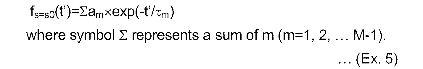
- With the use of the function form of (Ex. 5), the fitting parameter (am, τm) is set so that the function approximates the experimental data, thereby enabling the species compensation function fs0=-99(t') to be obtained. More specifically, when it is assumed that the unit of the magnetic field is ppm, and the unit of the time is second, the following expression well approximates the experimental data.

- Referring to
FIG. 5 , a curve indicated by a long dashed line of (C1) shows fs=-99(t') in (Ex. 6), which is drawn with being shifted up by 0.2 ppm with an origin of the time t1 for facilitation of distinction from (E1). That is, the curve (C1) in the figure represents fs=-99(t-t1)+0.2 ppm. The curves illustrated in the figure approximate each other within an error range of 0.01 ppm in the measurement results. When the curve (C1) is drawn without being shifted, in the section (t1 to t2), the curve (C1) completely coincides with the curve (E1), and cannot be distinguishable therefrom. - The generating compensation function f(s, t') for the term of the Z0 in this embodiment is obtained by taking asymmetry in the method represented by (Ex. 3) so as to approximate the measured value in a wide range by using the species compensation function fs0=-99(t'), and setting the fitting parameter so as to give excellent approximation. The following expression specifically represents the obtained generating compensation function (s, t').
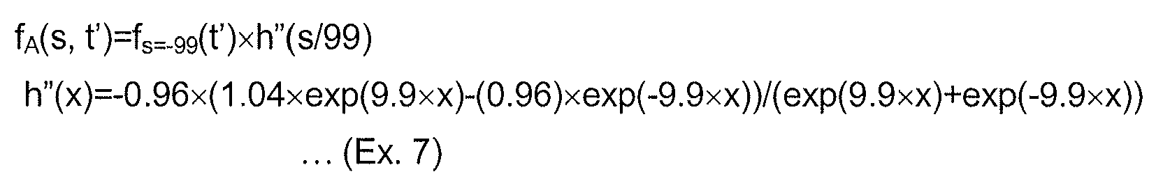
- With the generating compensation function fA(s, t') thus obtained, as will be described later, the fluctuation of the magnetic field intensity due to the history of the setting of the shim can be compensated within the error range of 0.01 ppm.
A specific example of the generating compensation function described above is described for facilitation of deeply understanding the method of obtaining and setting the generating compensation function. It should be noted that the generating compensation function satisfying the conditions is not limited to the above function. - In fact, the values of the compensation function gA(t)=ΣfA(sn, t-tn) can be obtained by using the generating compensation function fA obtained above in the overall section of the time t. In this expression, symbol Σ represents a sum of n (n=1, ... N-1). Also, the number of times N of the conducted setting is N=2 in the section (t1 to t2), and N=4 in the section (t3 ...).
Referring toFIG. 5 , a short dashed line indicated by (C2) is drawn with the compensation value thus calculated being reversed in a negative sign and shifted up by 0.4 ppm. That is, the curve C2 represents the curve of "-g(t)+0.4ppm". When the curve (C2) is drawn without being shifted, in the section (t1 to t2) and the section (t3 ...), the curve (C2) completely coincides with the curve (E1), and cannot be distinguishable therefrom.
This presents that the fluctuation found in the measured value in the figure can be compensated by adding the correction represented by the compensation function g(t) to the setting of the shim. - The above is summarized, and specific numerical values of the respective measured values and function values are shown in Table 1. The time t is shown at the leftmost column of Table 1. The other columns show the respective measured values and function values at the respective times t. Starting from the left, there are shown the values "p(t)" of the magnetic field when no correction is conducted, the species compensation function "fs=-99(t-t1)" represented by (Ex. 6), the compensation values inversed in sign "-g(t)", and values of the values "p(t)+g(t)" of the magnetic field when the compensation is conducted. The times t1, t2, and t3 at which the setting is conducted are noted in remarks column.
-
[Table 1] t/day p(t)/ppm f(t-t1)/ppm -g(t)/ppm (p(t)+g(t))/ppm remarks 0.000 98.853 0.000 0.500 98.854 5.407 0.000 0.875 1.400 t1 1.000 1.262 1.262 1.263 -0.001 1.500 0.928 0.937 0.938 -0.009 2.000 0.730 0.729 0.729 0.001 2.500 0.589 0.580 0.580 0.009 3.000 0.477 0.469 0.469 0.008 3.500 0.381 0.384 0.384 -0.002 4.000 0.314 0.317 0.317 -0.002 4.500 0.256 0.263 0.263 -0.007 5.000 0.218 0.220 0.220 -0.002 5.500 0.188 0.184 0.184 0.004 5.893 0.161 t2 5.903 0.160 t3 6.000 0.263 0.155 0.263 0.000 6.500 0.203 0.130 0.209 -0.006 7.000 0.110 0.170 7.500 0.093 0.141 8.000 0.079 0.117 - That the absolute value of "p(t)+g(t)" in the section (t1 to t2) and the section (t3 ...) is 0.01 ppm, or lower can be read from Table 1. This shows that the magnetic field fluctuation caused by the influence of the setting of the shim can be suppressed to 0.01 ppm or lower by the compensation according to the present invention.
- In this embodiment, a description will be given of a method of applying the present invention when the setting of the shim is given as a sequential change. The method of this embodiment approximates the sequential change of the setting with small stepwise changes.
This is realized by recording a change history of the shim at sufficiently small time intervals when the sequential change is set in the shim. More specifically, this embodiment is implemented in such a manner that when an arbitrary waveform is set, the setting of the waveform is approximated by combining a large number of small stepwise settings, and the stepwise setting of the approximation is continuously given to the method of the first embodiment. - In this method, when the precision of the approximation is to be enhanced, a capacity for storing the setting history, and the amount of calculation when calculating the compensation value are increased, to which attention needs to be paid. On the other hand, since the generating compensation function of the first embodiment which is obtained in the setting of the stepwise function form is used as it is, there is advantageous in that a prior specific provision is not required.
- This embodiment shows an example in which a method of the second invention is applied when the type of operation of the setting is a square wave. In the method according to the second invention, a value of the operation amount w must be scalar.
- In the experimental example illustrated in
FIG. 5 , the shim setting of a square wave (pulse) is conducted between the times (t2) and (t3). In the first embodiment, this pulse is treated as two stepwise changes including the stepwise change at the time (t2) and the stepwise change at the time (t3). On the other hand, one pulse combining two changes together can be regarded as one setting of the shim. In this case, the generating compensation function is defined for the setting of the shim of the pulse shape. - Since the pulse is characterized by a wave height (h) and a width (dt), the operation amount s becomes an array (h, dt) having those two elements. Also, since the magnitude of the pulse is characterized by the wave height x width, the scalar operation amount s' represented by s'=hxdt can be more easily used. Hence, for example, the generating compensation function represented by the following expression can be used.

- The above method for representatively indicating the operation amount of the setting of the pulse shape by its area can be applied to not the square pulse but a pulse of an arbitrary waveform. That is, the pulse of the arbitrary waveform is characterized by an area s' which is a value obtained by integrating a height of the waveform with time instead of hxdt in the case of a square.
- In this embodiment, the generating compensation function f'(h, dt, t') for the setting of the pulse shape is defined with t'>dt/2 as a domain assuming that the amount of time t' is measured from a center of the pulse. When it is assumed that the generating compensation function for the step function is f, f and f' have a relationship represented by the following expression.

In this expression, if a response of the system has a temporal correlation (response is changed depending on a state immediately before), an error corresponding to the magnitude of the correlation occurs in the measured value as dt is smaller at a right side of the expression, to which attention is paid. That is, when a plurality of settings of the shim is conducted in a short time, there is a possibility that the error occurs in the compensation made by the expression at the right side (the methods according to the first embodiment and the second embodiment). For that reason, when it is assumed that the setting of a specified combination is repetitively conducted, it is effective to treat a series of settings as the setting of one pulse shape as in this embodiment. - The generating compensation function f is defined as a function that approximates the measured value as with the generating compensation function f. In data processing, when the operation amount s of the setting in the first embodiment is replaced with the operation amount s' of the setting which has been converted into the scalar quantity in this embodiment. As a result, the method according to the first embodiment can be applied as it is.
- In this way, the shimming method according to the present invention can be implemented in the same method with the use of the generating compensation function suitable for the operation of the shim even if the operation of the shim is of the step shape or the arbitrary waveform. Even in the arbitrary waveform, the operation amount s can be converted into the scalar quantity by integrating the height h of the waveform with the time t to obtain the area s'. Therefore, the method according to the second invention can be applied.
On the other hand, when the operation amount of the setting is not represented by only the size of the waveform, the operation amount is treated as an array, and the generating compensation function corresponding to the array is allocated for treatment. - The generating compensation function for the term of the Z0 of the shim can be obtained by the normal NMR measurement as described in the first embodiment. Then, a description will be given of the measuring method when obtaining the generating compensation function for the terms other than the Z0 of the shim. For example, a first-order term (Z1, X1, Y1) of the shim is a term for correcting the gradient of the magnetic field (intensity of the magnetic field per a unit length) along the respective axes. Therefore, in order to obtain the generating compensation function related to this term, a change of the distribution of the magnetic field within the measurement space with time must be measured.
-
FIG. 6 illustrates a portion of a resonator neighborhood of the NMR probe device having seven probe elements within the measurement space as an example of the probe device according to the fourth invention. Referring toFIG. 6 , for facilitation of understanding the features of the probe device, a portion below a resonator mounting (630b) of a cylindrical housing (610b) is omitted. - As illustrated in
FIG. 7 , each NMR probe element (800) includes a measurement coil (810), a standard sample (820) disposed within the measurement coil (810), a tuning capacitor (830) connected in parallel to the measurement coil (810), and used for mainly adjusting a resonance frequency, a matching capacitor (840) inserted between the measurement coil (810) and a transmission line, and used for mainly adjusting impedance matching, and a coaxial cable (850) performing a transmission line of a measurement high-frequency signal. The respective parts are connected to each other by brazing. A resonator is configured by the measurement coil (810) and the tuning capacitor (830). All of those parts are made of nonmagnetic material so as not to affect the NMR measurement. The nonmagnetic property is not at least a ferromagnetic property, and has no large value of paramagnetic susceptibility and the like. - An electric equivalent circuit of the resonator neighborhood in the NMR probe element (800) is illustrated in
FIG. 8 . The respective capacitors of the tuning capacitor (830) and the matching capacitor (840) are configured by appropriately connecting a variable capacitor and a fixed-capacitance capacitor in parallel or in series, and have a certain degree of variable range.
The NMR probe element (800) only needs to obtain the lowest NMR signal. For that reason, a withstand voltage of the capacitors does not require that of the normal NMR probe. Therefore, a small-sized chip part can be used.
When a so-called semi-rigid coaxial cable is used as the coaxial cable (850), the measurement coil (810) can be supported by the coaxial cable (850). The coaxial cable (850) is fixed to the resonator mounting (630b). - A position of the resonator is shown with the center of the measurement coil as a reference point. The respective resonators are symmetrically arranged on the origin, and the respective axes of the X-axis, the Y-axis, and the Z-axis, and denoted by symbols (R00), (RX-), (RX+), (RY-), (RY+), (RZ-), and (RZ+). Also, a distance between the resonator (RX-) and the resonator (RX+) is denoted by (LX), a distance between the resonator (RY-) and the resonator (RY+) is denoted by (LY), and a distance between the resonator (RZ-) and the resonator (RZ+) is denoted by (LZ).
- Any standard samples are available if an NMR signal with some degree of sharpness is obtained. Among them, deuterium water (D2O) in which hydrogen atoms (H) in water (H2O) are replaced with deuterium atoms (D) is an optimum sample because treatment is easy, and the resonance frequency is reasonable. In the NMR device using 1 H-930 MHz magnet, the resonance frequency of the NMR of diplon is about 143 MHz. In the frequency of this degree, when the resonator is configured by a coil and a capacitor, a size of the resonator is sufficiently small as compared with the wavelength, and a so-called lumped parameter circuit treatment is efficient. This results in such advantages that the design and adjustment of the resonator are easy. In particular, when a selective switch (switch) is inserted between the probe element and a spectrometer so that the probe element to be measured can be easily selected, in order to suppress the insertion loss of the switch, it is preferable that the measurement frequency is lower.
- In this embodiment, deuterium water is used as the standard sample. The deuterium water is sealed in a resin tube by melting the resin. A method of sealing the sample in the tube is not limited to melting of the resin, but can be conducted by resin of a rubber closure or adhesive. In this way, since deuterium water is small in natural abundance ratio, a contaminating signal from a vessel in use may not be worried, resulting in such an advantage that option of its material is wide. A deuterated solvent such as deuterated chloroform is also similarly available. However, because the deuterated solvent is low in boiling point, there is a difficulty in requiring a technique for sealing in the tube.
- When the NMR measurement is conducted by the aid of a probe element E (E=R00, RX-, RX+, ...), a resonance frequency FE at that position is obtained. A magnetic gradient DFx along the X-axis is represented by DFX=(FRX+-FRX-)/LX. The DFx corresponds to the term X1 of the shim.
- In this embodiment, a probe element (R00) located in the center (origin) of the magnetic field can be used not only for obtaining the generating compensation function for the term of the Z0, but also for verification of the measured value of the higher-order term. Naturally, even if the magnetic gradient fluctuates due to the setting of the shim of the higher-order term, the magnetic field of the origin would not fluctuate. If the magnetic field of the origin largely fluctuates, there is a high possibility that a positional relationship of the superconducting magnet, the shim coil, and the probe, or the setting of a conversion expression within the shim coil driving device is displaced. Therefore, the displacement of the setting should be corrected.
As development of this embodiment, in the normal NMR probe in which the NMR measurement coil is arranged in the origin, there can be configured a probe in which the probe elements are appropriately arranged in an unoccupied space so as to perform both of the normal measurement and the magnetic gradient measurement. - A selector switch using a high-frequency relay can be inserted between the probe and the NMR spectrometer. Further, selection of the probe elements is designated during a pulse sequence, and on the basis of the designation, the selector switch can be controlled. With this configuration, a plurality of the probe elements can conduct the measurement in parallel by time sharing, thereby remarkably reducing the measurement time.
- As one of devices for measuring the magnetic field distribution within the measurement space, there is a shim robot that obtains the distribution of the magnetic field by scanning the space. However, in the present invention, since not the absolute value of the magnetic field, but a change of the magnetic field with time is important, the diversion of the shim robot is not proper. This is because travel of the shim robot within the probe adversely affects the measurement.
-
- PATENT DOCUMENT 1:
JP-A-2001-218750 -
- NON-PATENT DOCUMENT 1:
Experimental Chemical Course 8 "NMR/ESR", Ver. 5, The Chemical Society of Japan (Maruzen, 2006
According to the third invention, there is provided an NMR probe device used for experimentally obtaining the generating compensation function in the shimming device according to the first invention or the second invention, in which the NMR probe device includes at least two NMR probe elements, each of the NMR probe elements contains a standard sample for magnetic field intensity measurement therein, and the NMR probe elements are set at given discrete positions in a measurement space.
Claims (3)
- A shimming device that compensates stability and homogeneity of a magnetic field of a superconducting magnet with a shim coil, wherein at least one term of the shim is controlled by the following means (1) to (4).(1) shim setting recording means that records, when the setting of the shim is conducted, a set value u of the shim, a type w of set operation, operation amount s of setting, and the time t of setting, by associating the setting finally conducted with an index N-1 so as to be referred to as (wn, un, sn, tn) by the aid of an index n which is a value of 0 to N-1 where the number of times of setting is N;(2) generating compensation function supply means that supplies a generating compensation function "fw(s,t')" that is a function having the type w of the operation, the operation amount s, and the amount of time t' as arguments, which has a property to become 0 when the amount of time t' is infinite, and is set so as to approximately compensate a magnetic field fluctuation attributable to individual setting;(3) compensation value calculating means that calculates a compensation value at the time t by the aid of a compensation function assuming that symbol "Σ" represents a sum of n (0, 1, 2 ... N-1), and the compensation function "g(t)" is a function of the time t which is expressed as "g(t)=Σfwn(sn, t-tn)" by the generating compensation function and the setting of the shim conducted before the time t; and(4) shim coil driving means that drives the shim coil by the aid of a sum of the compensation value obtained by the compensation value calculating means, and a latest set value uN-1.
- The shimming device according to claim 1, wherein the generating compensation function is expressed as "fw s=s0(t')×h(s/s0)" assuming that the generating compensation function "fw(s0, t')" when the operation amount s of setting has a specific value s0 is a species compensation function "fw s=s0(t')" which is a function of the amount of time t', the operation amount s of setting is normalized by the aid of s0, and a polynomial function h of the normalized operation amount "s/s0" is h(s/s0).
- An NMR probe device used for experimentally obtaining the generating compensation function in the shimming device according to claim 1 or 2, wherein the NMR probe device includes at least two NMR probe elements, each of the NMR probe elements contains a standard sample for magnetic field intensity measurement therein, and the NMR probe elements are set at given discrete positions in a measurement space.
Applications Claiming Priority (2)
| Application Number | Priority Date | Filing Date | Title |
|---|---|---|---|
| JP2009158687 | 2009-07-03 | ||
| PCT/JP2010/061399 WO2011002098A1 (en) | 2009-07-03 | 2010-07-05 | Shimming device for superconducting magnet |
Publications (2)
| Publication Number | Publication Date |
|---|---|
| EP2450720A1 true EP2450720A1 (en) | 2012-05-09 |
| EP2450720A4 EP2450720A4 (en) | 2013-03-27 |
Family
ID=43411166
Family Applications (1)
| Application Number | Title | Priority Date | Filing Date |
|---|---|---|---|
| EP10794266A Withdrawn EP2450720A4 (en) | 2009-07-03 | 2010-07-05 | MAGNETIC FIELD HOMOGENIZATION DEVICE FOR SUPERCONDUCTING MAGNET |
Country Status (4)
| Country | Link |
|---|---|
| US (1) | US9075120B2 (en) |
| EP (1) | EP2450720A4 (en) |
| JP (1) | JP5594632B2 (en) |
| WO (1) | WO2011002098A1 (en) |
Cited By (2)
| Publication number | Priority date | Publication date | Assignee | Title |
|---|---|---|---|---|
| CN104122518A (en) * | 2013-04-25 | 2014-10-29 | 上海联影医疗科技有限公司 | Magnetic resonance imaging system and passive shimming device |
| CN108761364A (en) * | 2018-05-21 | 2018-11-06 | 上海健康医学院 | A kind of high-performance NMR relaxation analyzer lock field system and its application |
Families Citing this family (4)
| Publication number | Priority date | Publication date | Assignee | Title |
|---|---|---|---|---|
| JP5769110B2 (en) * | 2011-07-27 | 2015-08-26 | 日本電子株式会社 | Nuclear magnetic resonance apparatus and magnetic field correction method |
| CN106443535B (en) | 2013-05-21 | 2019-04-23 | 上海联影医疗科技有限公司 | The system of imaging magnetic field measurement and correction in magnetic resonance device |
| JP6617135B2 (en) * | 2015-02-25 | 2019-12-11 | 株式会社日立製作所 | Magnetic resonance imaging apparatus, static magnetic field uniformity adjustment method, program, and computer |
| DE102015204953B3 (en) * | 2015-03-19 | 2016-08-11 | Siemens Healthcare Gmbh | Method for magnetic resonance imaging |
Family Cites Families (10)
| Publication number | Priority date | Publication date | Assignee | Title |
|---|---|---|---|---|
| JPS612047A (en) * | 1984-06-15 | 1986-01-08 | Jeol Ltd | Nuclear magnetic resonator device |
| JPH01136645A (en) | 1987-11-25 | 1989-05-29 | Toshiba Corp | Magnetic resonance imaging apparatus |
| JPH01155836A (en) * | 1987-12-14 | 1989-06-19 | Toshiba Corp | Magnetic resonance imaging apparatus |
| US5006804A (en) * | 1989-12-04 | 1991-04-09 | General Electric Company | Method of optimizing shim coil current selection in magnetic resonance magnets |
| US5345178A (en) * | 1992-04-21 | 1994-09-06 | Siemens Aktiengesellschaft | Method for setting the current through shim coils and gradient coils in a nuclear magnetic resonance apparatus |
| DE4217496C2 (en) * | 1992-05-27 | 1994-06-16 | Bruker Analytische Messtechnik | Shim method |
| JPH06123764A (en) * | 1992-10-12 | 1994-05-06 | Jeol Ltd | NMR shim value setting method |
| JP3847079B2 (en) | 2000-11-21 | 2006-11-15 | ジーイー・メディカル・システムズ・グローバル・テクノロジー・カンパニー・エルエルシー | MRI equipment |
| US7605589B2 (en) * | 2006-04-10 | 2009-10-20 | Bruker Biospin Ag | Method for automatic shimming for nuclear magnetic resonance spectroscopy |
| JP2008046003A (en) * | 2006-08-17 | 2008-02-28 | National Institute For Materials Science | Magnetic field fluctuation removal method in NMR |
-
2010
- 2010-07-05 WO PCT/JP2010/061399 patent/WO2011002098A1/en not_active Ceased
- 2010-07-05 US US13/381,204 patent/US9075120B2/en not_active Expired - Fee Related
- 2010-07-05 JP JP2011521003A patent/JP5594632B2/en not_active Expired - Fee Related
- 2010-07-05 EP EP10794266A patent/EP2450720A4/en not_active Withdrawn
Cited By (4)
| Publication number | Priority date | Publication date | Assignee | Title |
|---|---|---|---|---|
| CN104122518A (en) * | 2013-04-25 | 2014-10-29 | 上海联影医疗科技有限公司 | Magnetic resonance imaging system and passive shimming device |
| CN104122518B (en) * | 2013-04-25 | 2017-12-22 | 上海联影医疗科技有限公司 | Magnetic resonance imaging system and its passive shimming device |
| CN108761364A (en) * | 2018-05-21 | 2018-11-06 | 上海健康医学院 | A kind of high-performance NMR relaxation analyzer lock field system and its application |
| CN108761364B (en) * | 2018-05-21 | 2020-06-05 | 上海健康医学院 | A nuclear magnetic resonance relaxation analyzer locking field system and application method thereof |
Also Published As
| Publication number | Publication date |
|---|---|
| US9075120B2 (en) | 2015-07-07 |
| JPWO2011002098A1 (en) | 2012-12-13 |
| JP5594632B2 (en) | 2014-09-24 |
| US20120176136A1 (en) | 2012-07-12 |
| WO2011002098A1 (en) | 2011-01-06 |
| EP2450720A4 (en) | 2013-03-27 |
Similar Documents
| Publication | Publication Date | Title |
|---|---|---|
| EP2450720A1 (en) | Shimming device for superconducting magnet | |
| US10658109B2 (en) | System and method for electromagnet coil construction and operation | |
| Rahbarnia et al. | Diamagnetic energy measurement during the first operational phase at the Wendelstein 7-X stellarator | |
| CN103596496B (en) | MR imaging apparatus and leaning magnetic field waveform presumption method | |
| CN102958434B (en) | Magnetic resonance imaging device and its control device | |
| US4647858A (en) | Methods for overcoming transient magnetic field inhomogeneity in nuclear magnetic resonance imaging | |
| EP0560396B1 (en) | Nuclear magnetic resonance imaging with improved image quality and operation efficiency | |
| EP3470828A2 (en) | Real-time methods for magnetic resonance spectra acquisition | |
| Rund et al. | Magnetic resonance RF pulse design by optimal control with physical constraints | |
| US12055609B2 (en) | Method and control unit for compensation of eddy current induced magnetic fields in magnetic resonance imaging | |
| US11137469B2 (en) | Method and device for controlling a magnetic resonance imaging system | |
| US7002343B2 (en) | Method for determining a compensation setting for an eddy current field | |
| US11378639B2 (en) | System and method to reduce eddy current artifacts in magnetic resonance imaging | |
| US20190310332A1 (en) | Magnetic field gradient coil assembly with integrated modulator and switch unit | |
| US20080164878A1 (en) | Minimum Energy Shim Coils For Magnetic Resonance | |
| Hua et al. | Analysis of on‐and off‐resonance magnetization transfer techniques | |
| Inoue et al. | Diamagnetic energy measurements and evaluation of poloidal beta and internal inductance during the first operational phase at JT-60SA | |
| KR20010049606A (en) | Selective excitation method and apparatus, and magnetic resonance imaging method and apparatus | |
| JP3339885B2 (en) | Magnetic resonance imaging equipment | |
| Kimmlingen | Magnetic field gradients | |
| JP4890945B2 (en) | Magnetic resonance imaging system | |
| Ahmed | Active magnetic compensation prototype for a neutron electric dipole moment experiment | |
| Srinivas et al. | Linear Bloch–Siegert phase‐encoded low‐field MRI: RF coils, pulse sequence, and image reconstruction | |
| Kim et al. | Field uniformity enhancement in a prototype high-temperature superconducting dipole magnet | |
| JPWO2015072301A1 (en) | Magnetic resonance imaging system |
Legal Events
| Date | Code | Title | Description |
|---|---|---|---|
| PUAI | Public reference made under article 153(3) epc to a published international application that has entered the european phase |
Free format text: ORIGINAL CODE: 0009012 |
|
| 17P | Request for examination filed |
Effective date: 20120201 |
|
| AK | Designated contracting states |
Kind code of ref document: A1 Designated state(s): AL AT BE BG CH CY CZ DE DK EE ES FI FR GB GR HR HU IE IS IT LI LT LU LV MC MK MT NL NO PL PT RO SE SI SK SM TR |
|
| DAX | Request for extension of the european patent (deleted) | ||
| A4 | Supplementary search report drawn up and despatched |
Effective date: 20130222 |
|
| RIC1 | Information provided on ipc code assigned before grant |
Ipc: G01R 33/3815 20060101ALI20130218BHEP Ipc: G01R 33/389 20060101AFI20130218BHEP Ipc: A61B 5/055 20060101ALI20130218BHEP Ipc: G01R 33/3875 20060101ALI20130218BHEP |
|
| 17Q | First examination report despatched |
Effective date: 20150602 |
|
| STAA | Information on the status of an ep patent application or granted ep patent |
Free format text: STATUS: THE APPLICATION IS DEEMED TO BE WITHDRAWN |
|
| 18D | Application deemed to be withdrawn |
Effective date: 20151013 |