EP2450668A1 - A method for tracking the position and the heading of a vehicle using dead reckoning and a tracking device for carrying out the method - Google Patents
A method for tracking the position and the heading of a vehicle using dead reckoning and a tracking device for carrying out the method Download PDFInfo
- Publication number
- EP2450668A1 EP2450668A1 EP10405212A EP10405212A EP2450668A1 EP 2450668 A1 EP2450668 A1 EP 2450668A1 EP 10405212 A EP10405212 A EP 10405212A EP 10405212 A EP10405212 A EP 10405212A EP 2450668 A1 EP2450668 A1 EP 2450668A1
- Authority
- EP
- European Patent Office
- Prior art keywords
- wheel angle
- app
- wheel
- cal
- velocity
- Prior art date
- Legal status (The legal status is an assumption and is not a legal conclusion. Google has not performed a legal analysis and makes no representation as to the accuracy of the status listed.)
- Granted
Links
- 238000000034 method Methods 0.000 title claims description 37
- 238000004364 calculation method Methods 0.000 claims abstract description 37
- 238000005259 measurement Methods 0.000 claims description 26
- 238000012545 processing Methods 0.000 claims description 7
- 238000012937 correction Methods 0.000 claims description 6
- 238000013500 data storage Methods 0.000 claims 1
- 230000006870 function Effects 0.000 description 14
- 229920000535 Tan II Polymers 0.000 description 11
- SGTNSNPWRIOYBX-UHFFFAOYSA-N 2-(3,4-dimethoxyphenyl)-5-{[2-(3,4-dimethoxyphenyl)ethyl](methyl)amino}-2-(propan-2-yl)pentanenitrile Chemical compound C1=C(OC)C(OC)=CC=C1CCN(C)CCCC(C#N)(C(C)C)C1=CC=C(OC)C(OC)=C1 SGTNSNPWRIOYBX-UHFFFAOYSA-N 0.000 description 4
- 241000238876 Acari Species 0.000 description 3
- 238000009795 derivation Methods 0.000 description 3
- 238000010586 diagram Methods 0.000 description 3
- 230000014509 gene expression Effects 0.000 description 3
- 238000011156 evaluation Methods 0.000 description 2
- 101100264195 Caenorhabditis elegans app-1 gene Proteins 0.000 description 1
- 240000006829 Ficus sundaica Species 0.000 description 1
- 238000013459 approach Methods 0.000 description 1
- 238000009499 grossing Methods 0.000 description 1
- 238000009434 installation Methods 0.000 description 1
- 239000011159 matrix material Substances 0.000 description 1
- 238000012544 monitoring process Methods 0.000 description 1
- 239000000725 suspension Substances 0.000 description 1
Images


Classifications
-
- G—PHYSICS
- G01—MEASURING; TESTING
- G01C—MEASURING DISTANCES, LEVELS OR BEARINGS; SURVEYING; NAVIGATION; GYROSCOPIC INSTRUMENTS; PHOTOGRAMMETRY OR VIDEOGRAMMETRY
- G01C22/00—Measuring distance traversed on the ground by vehicles, persons, animals or other moving solid bodies, e.g. using odometers, using pedometers
- G01C22/02—Measuring distance traversed on the ground by vehicles, persons, animals or other moving solid bodies, e.g. using odometers, using pedometers by conversion into electric waveforms and subsequent integration, e.g. using tachometer generator
- G01C22/025—Differential odometers
-
- G—PHYSICS
- G01—MEASURING; TESTING
- G01C—MEASURING DISTANCES, LEVELS OR BEARINGS; SURVEYING; NAVIGATION; GYROSCOPIC INSTRUMENTS; PHOTOGRAMMETRY OR VIDEOGRAMMETRY
- G01C21/00—Navigation; Navigational instruments not provided for in groups G01C1/00 - G01C19/00
- G01C21/26—Navigation; Navigational instruments not provided for in groups G01C1/00 - G01C19/00 specially adapted for navigation in a road network
- G01C21/28—Navigation; Navigational instruments not provided for in groups G01C1/00 - G01C19/00 specially adapted for navigation in a road network with correlation of data from several navigational instruments
Definitions
- the invention concerns a method for keeping track of the position and the heading of a vehicle using tracking by dead reckoning. Such methods are used in cars and other vehicles, often complementing determination of the vehicle position by GNSS, in particular, where GNSS signals are temporarily too weak or unavailable, e.g., in tunnels, car parkings and the like.
- the invention also concerns a tracking device for carrying out the method.
- the advantages of the method according to the invention are particularly pronounced where large wheel angles occur, e.g., in underground car parkings and similar environments where, at the same time, GNSS signals tend to be weak or absent.
- the method can be implemented in ways which are very economical as to processing power and memory requirements.
- the sensor measurements can be used in combination with GNSS measurements where such are available, e.g., by feeding both to a tightly coupled Kalman filter.
- 'dead reckoning In vehicles so-called 'dead reckoning' is often used for tracking the position of the vehicle by determining the velocities of the wheels and using the results as a basis for updating the vehicle position, either in combination with GNSS or, where GNSS is not available, by itself. Dead reckoning and GNSS tracking calculations can be carried out in an appropriate tracking device, usually a component of the vehicle or attached to the same, and the results displayed or made use of in other ways.
- a wheel velocity is normally determined from sensor measurements, usually signals known as 'wheel ticks' which are produced at particular rotational positions separated by fixed angular increments. Where sensor measurements from the rear wheels are used, deriving the speed and heading rate of the vehicle is usually straightforward as wheel angles may be assumed to be constant and equal to zero.
- the vehicle ( Fig. 1 ) comprises a rigid frame 1 on which rear wheels 2a,b and front wheels 3a,b are mounted.
- the vehicle is steerable in that the front wheels 3a,b are rotatable about vertical axes passing through their centres and may assume wheel angles covering an interval containing 0° which value corresponds to a motion of the vehicle straight ahead.
- a tracking installation comprises a tracking device 4 which is fixed to the frame 1 and wheel tick units 5a,b monitoring the rotations of the front wheels 3a;b or other sensors producing sensor measurements from which the wheel velocities of the front wheels 3a,b can be derived.
- a GNSS antenna 6 which is also mounted on the frame 1, feeds, like the wheel tick units 5a,b, data to the tracking device 4.
- the tracking device 4 is configured to process the sensor measurements, i.e., signals from the wheel tick units 5a,b, in order to extract a position and a heading of the vehicle from them as well as GNSS signals received by the GNSS antenna 6 and contains the components for storing and processing data and outputting results etc. which are required for the purpose. It is assumed that the frame 1 and the suspensions of the rear wheels 2a,b and the front wheels 3a,b are symmetrical with respect to an axis of symmetry which passes through the midpoints between the rear wheels 2a,b and the front wheels 3a,b.
- x r v cos ⁇ l ⁇ 1 - a tan ⁇ l
- v r v cos ⁇ r ⁇ 1 + a tan ⁇ r
- v ⁇ l v 1 - a tan ⁇ l ⁇ - tan ⁇ l
- the branch of the solution (31) which corresponds to a range for ⁇ ex containing 0 - motion of the vehicle straight ahead - is the first branch where the square root in (31) and consequently in (33), (34) is preceded by a plus sign and which applies for 0 ⁇
- ⁇ lim with ⁇ lim ⁇ ex ( P max ) whereas the second branch, with a minus sign in front of the square root, covers ⁇ lim ⁇
- p v l - v r v l + v r
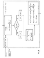
- Fig. 2 provides an overview.
- consecutive filter cycles are carried out in the tracking device 4, each covering a cycle interval.
- a complete filter cycle of the tightly coupled Kalman filter which is preferably used comprises a prediction step and, where GNSS measurements are available, a correction step which also takes those measurements into account.
- the use of a Kalman filter makes it possible to deal adequately with the random influences which usually affect measurements.
- a prediction step consists of N time update steps each covering a measuring interval ⁇ t of, e.g., 0.1s, with N being, e.g., 10, and consequently covers a cycle interval N ⁇ t which, in the example, has a duration of Is.
- the state vector of the vehicle is set to the values determined at the end of the previous cycle interval, or, at the beginning of the process, to some initial values, which provides a starting point comprising starting values x ref ,0 , H 0 for the position and the heading as well as values for the wheel tick calibration factors f l , f r .
- a raw velocity T l of the left front wheel 3a and a raw velocitiy T r of the right front wheel 3b are derived from the wheel tick numbers as registered by the wheel tick units 5a;b for each of the N time update intervals, the numbers being low pass filtered for smoothing out random variations.
- the calculation wheel angle ⁇ cal is assumed to be a constant at every time update step but the covariance matrix is modified to add process noise accounting for the random factors which in fact influence the value of the said angle used in the calculation.
- the result of the prediction step i.e., of the N th update step, consisting of state and accuracy information, is, where GNSS measurements are available, then used in a correction step of the tightly coupled Kalman filter which also processes the said GNSS measurements.
- the filter cycle is finalised and a new state vector determined which comprises a corrected position x ref,N and heading H N to be used as a starting point x ref ,0 H 0 in the first time update step of the prediction step in the next filter cycle as well as recalibrated wheel tick calibration factors f l , f r .
- the position and heading are output by the tracking device 4 for display or other purposes, e.g., for use in processing in a navigation device.
- ⁇ app is not too large, e.g.,
- the tolerance range is determined by the consideration that any angle within the same is close enough to ⁇ ex to insure that the error introduced by using it in stead of ⁇ ex is not significant.
- the value of ⁇ cal from (65) can then be used in (63), (64).
- the tolerance range about ⁇ ex can be defined, for instance, by a certain amount or percentage of acceptable deviation, e.g., deviation by not more than 2°, preferably by not more than 1°.
- Other criteria e.g., a maximum acceptable deviation of the velocity ⁇ or the heading rate h or both, in absolute or relative terms, are also possible.
- ⁇ app is within the tolerance range of ⁇ ex ⁇ 1°
- ⁇ cal is set equal to ⁇ app .
- ⁇ app ⁇ thr where ⁇ app reaches the boundary of the tolerance range, ⁇ cal is switched to ⁇ ex .
- the corresponding value of ⁇ ex can then be determined by, e.g., linear, interpolation between neighbouring values read from the table. This method does not require much processing power in the tracking device 4 and memory requirements are also modest.
- tan ⁇ ex can vice versa be expressed as a function of tan ⁇ app inserting p from (66) into (60).
- These relations can be used to calulate and permanently store a look-up table containing values for tan ⁇ ex as a function of tan ⁇ app .
- This can be used to prepare a look-up table with corresponding pairs of cos ⁇ app and cos ⁇ ex from which cos ⁇ cal can be easily determined for
- (75) or (76) can, in particular, be employed where tan ⁇ ex is rather large, e.g., where ⁇ app > ⁇ thr , whereas (63) is used for smaller ⁇ app . But it is also possible to use the said formulae over the whole range, i.e., with tan ⁇ cal .
- observation equations expressing the raw wheel velocities T l , T r as functions of the states ⁇ , h, f l and f r are used where ⁇ cal figures as a parameter.
- equations T l 1 f l ⁇ v cos ⁇ cal + bh cos ⁇ cal
- T l and T r are treated as observations and f l , f r , ⁇ and h as unknowns.
Landscapes
- Engineering & Computer Science (AREA)
- Radar, Positioning & Navigation (AREA)
- Remote Sensing (AREA)
- Physics & Mathematics (AREA)
- General Physics & Mathematics (AREA)
- Automation & Control Theory (AREA)
- Navigation (AREA)
- Position Fixing By Use Of Radio Waves (AREA)
- Control Of Driving Devices And Active Controlling Of Vehicle (AREA)
Abstract


Description
- The invention concerns a method for keeping track of the position and the heading of a vehicle using tracking by dead reckoning. Such methods are used in cars and other vehicles, often complementing determination of the vehicle position by GNSS, in particular, where GNSS signals are temporarily too weak or unavailable, e.g., in tunnels, car parkings and the like. The invention also concerns a tracking device for carrying out the method.
- Methods for tracking the position and heading of a vehicle by dead reckoning using rear wheel velocities derived from sensor measurements are well known. Although the evaluation of front wheel velocities is more complicated due to the variability of the wheel angles methods using only front wheel velocities have also been proposed. So far only approximate solutions connecting the velocity and heading rate of the vehicle to left and right front wheel velocities have been employed, s., e.g.: Ch. Hollenstein, E. Favey, C. Schmid, A. Somieski, D. Ammann: 'Performance of a Low-cost Real-time Navigation System using Single-frequency GNSS Measurements Combined with Wheel-tick Data', Proceedings of ION GNSS 2008 Meeting, Savannah, September 2008. According to this paper, the wheel angle was determined by iterative methods. The approximations used can compromise the precision of the tracking where large wheel angles cannot be excluded.
- It is the object of the invention to provide a method for keeping track of the position and heading of a vehicle according to the generic part of
claim 1 which provides improved precision. This object is achieved by the features in the characterising portion ofclaim 1. - The advantages of the method according to the invention are particularly pronounced where large wheel angles occur, e.g., in underground car parkings and similar environments where, at the same time, GNSS signals tend to be weak or absent. The method can be implemented in ways which are very economical as to processing power and memory requirements.
- The sensor measurements can be used in combination with GNSS measurements where such are available, e.g., by feeding both to a tightly coupled Kalman filter.
- It is another object of the invention to provide a tracking device suitable for carrying out the method according to the invention.
- In the following the invention is described in more detail with reference to drawings which only illustrate an examplary embodiment.
- Fig. 1
- schematically shows a vehicle comprising a tracking device according to the invention and whose position and heading is being tracked using the method according to the invention,
- Fig. 2
- shows a flow diagram of the method according to the invention,
- Fig. 3
- shows a part of the flow diagram of
Fig. 2 in more detail, and - Fig. 4
- shows a diagram with an approximate solution and an exact solution for an intermediate wheel angle δ as shown in
Fig. 1 . - In vehicles so-called 'dead reckoning' is often used for tracking the position of the vehicle by determining the velocities of the wheels and using the results as a basis for updating the vehicle position, either in combination with GNSS or, where GNSS is not available, by itself. Dead reckoning and GNSS tracking calculations can be carried out in an appropriate tracking device, usually a component of the vehicle or attached to the same, and the results displayed or made use of in other ways.
- A wheel velocity is normally determined from sensor measurements, usually signals known as 'wheel ticks' which are produced at particular rotational positions separated by fixed angular increments. Where sensor measurements from the rear wheels are used, deriving the speed and heading rate of the vehicle is usually straightforward as wheel angles may be assumed to be constant and equal to zero.
- In some cases, however, sensor measurements from rear wheels are not available and speed and heading rate must be derived from front wheel sensor measurements alone. This requires more involved calculations as the variable wheel angles which need to be taken into account must be derived from the wheel ticks as well unless they are available otherwise, e.g., from direct measurements.
- In the following the case where wheel angles must be derived solely from front wheel sensor measurements is described in detail. It is assumed that the vehicle (
Fig. 1 ) comprises arigid frame 1 on whichrear wheels 2a,b andfront wheels 3a,b are mounted. The vehicle is steerable in that thefront wheels 3a,b are rotatable about vertical axes passing through their centres and may assume wheel angles covering an interval containing 0° which value corresponds to a motion of the vehicle straight ahead. A tracking installation comprises a tracking device 4 which is fixed to theframe 1 andwheel tick units 5a,b monitoring the rotations of thefront wheels 3a;b or other sensors producing sensor measurements from which the wheel velocities of thefront wheels 3a,b can be derived. AGNSS antenna 6 which is also mounted on theframe 1, feeds, like thewheel tick units 5a,b, data to the tracking device 4. The tracking device 4 is configured to process the sensor measurements, i.e., signals from thewheel tick units 5a,b, in order to extract a position and a heading of the vehicle from them as well as GNSS signals received by theGNSS antenna 6 and contains the components for storing and processing data and outputting results etc. which are required for the purpose. It is assumed that theframe 1 and the suspensions of therear wheels 2a,b and thefront wheels 3a,b are symmetrical with respect to an axis of symmetry which passes through the midpoints between therear wheels 2a,b and thefront wheels 3a,b. - In the following derivations it is assumed that there is no slippage and that the momentary motion of the wheel centre follows in each case the direction implied by the wheel angle and, for simplicity, that the vehicle moves in a level plane defined by a northerly direction (n) and an easterly direction (e). Every vector x in the plane therefore consists of a northerly component and an easterly component, that is, x =(x (n), x (e)). If the plane the vehicle moves on is inclined it is straightforward to project its motion onto a level plane.
- In the example the state of the vehicle can be described by the position of a reference point x ref =(xref (n),xref (e)) fixed on the
frame 1 of the vehicle and the heading H, i.e., the angle between the northerly direction and the longitudinal direction of the said frame, where the angle is measured clockwise. - In dead reckoning tracking of the vehicle position, a new state assumed by the vehicle at the end of a (k+1) th time update interval of length Δt can be derived from the state at the end of the previous time update interval using equations of motion


where ν is the momentary scalar velocity and h the momentary heading rate, i.e., the angular velocity of the vehicle. For every time update step the scalar velocity ν and the heading rate h must therefore be determined from the velocities ν l and ν r of the left and right front wheels. They correspond to raw velocities Tl , Tr derived from numbers of wheel ticks registered during the time interval Δt according to

with wheel tick calibration factors fl and fr which depend on the wheel radii. - For simplicity it is (
Fig. 1 ) assumed in the following that the vehicle is at the moment oriented in an easterly direction, i.e., that its heading H equals 90°, and that the reference point x ref of the vehicle, defined as the midpoint between the centres of the rear wheels, is at the origin O. Thereby the below derivations can be carried out in a simple manner in the fixed coordinate system described above. As the results do not depend on the orientation of the vehicle and its position on the plane this does not imply a loss of generality. - According to the above assumptions,

and the midpoint between the centres of the front wheels is at
where l is the wheel base of the vehicle and the centres of the front wheels are at

with b equalling one half of the front track gauge. - The vehicle, that is, its reference point x ref , moves at the moment with a velocity ν in an easterly direction:

- The corresponding velocities of the other relevant points x f , x l , x r are

and

where ν f , ν l and ν r each designate a scalar velocity, i.e., the length of the respective vector and δ l , δ r are the wheel angles of the left and the right front wheel, respectively, whereas an intermediate wheel angle δ is the angle between the easterly direction and the momentary direction of motion of x f . - Defining

with
where r is the distance between x ref and the momentary centre of rotation of the vehicle C at (-r,0) and


- Similarly, from

one has
- From the rigidity of the vehicle it follows that

and together with (5), (6), (8) and (9) that l(ν fcosδ - ν) = 0 and
and finally with (9)
- Using the same method for x l , x r yields


and

and with (13a) and (13b), respectively, because of


and

- The scalar heading rate is

where the subscript ⊥ signifies the component of the vector which is perpendicular to the longitudinal axis of the vehicle, which leads to
where it is assumed that a heading rate in the clockwise direction carries the plus sign. - Defining V + and V - as

and
one gets from (20a) and (20b)
and
or
and

- This quadratic equation for ν2 has a
solution 
with two branches, one with a plus-sign and one with a minus sign in front of the square root. - With

(29) becomes
and for ν one gets accordingly
where positive ν signifies forward motion and negative ν backward motion of the vehicle. (27) and (31) lead, together with (30), to exact solutions of equations (20a), (20b) for the tangent of the wheel angle δ and the said wheel angle itself:

(33) can be inverted and P represented as a function of y = tanδ ex :
- This antisymmetric function has extrema at


where

- These are the values of P where the argument of the square root in (31) is zero and δ ex assumes the values


- The branch of the solution (31) which corresponds to a range for δ ex containing 0 - motion of the vehicle straight ahead - is the first branch where the square root in (31) and consequently in (33), (34) is preceded by a plus sign and which applies for 0≤|δ ex |≤δ lim with δ lim = δ ex (Pmax ) whereas the second branch, with a minus sign in front of the square root, covers δ lim ≤|δ ex |≤90°. This implies that if |δ ex | may assume values larger than δ lim the solution is not everywhere unique as there are subranges of δ ex surrounding δ lim and -δ lim where two solutions exist and it is not possible to pick the correct one on the basis of the momentary wheel velocities alone. However, for δ ex =δ lim we have, by (13b),

and as long as the wheel angle of the right front wheel δ r is, e.g., by mechanical constraints, limited by δ r ≤δ wlim - and, by symmetry - the wheel angle of the left front wheel δl by δ l ≥-δ wlim - the solution is unique as only the first branch in (31) and (33), (34) can apply. As δ wlim is always larger than 45° and with most vehicles the wheel angles are limited to values smaller than that thelimitation 0≤|δ ex |≤δ lim will be assumed to hold in the following. - With this assumption (31) to (34) can be restated as


and
- The heading rate h can then be derived from (22), (41) and (42) as

- The exact solutions derived above for ν, δ and h are rather complicated and, in particular, lead to unwieldy expressions for the derivatives which are needed where the dependence of ν and h upon the scalar wheel velocities ν l and ν r are used in a Kalman filter or a least squares or similar evaluation. Working with them in real time situations where processing power and time are limited is therefore often not practicable. There are, however, more tractable approximations which are usually good enough, at least as long as the wheel angles are not too large. For large wheel angles the said approximations can then be appropriately corrected.
- A relatively simple approximate solution which is well known per se from geometrical considerations can be developed starting with (20a) and (20b). (20a) can be rewritten as

- The square root can then be expanded, i.e., linearised, about


- Disregarding the higher order terms, one arrives at


where the suffix app signifies 'approximate' and ν r has been derived in a manner entirely analogous to the derivation of ν l above. - From (47a), (47b) follow

and
- Defining

one has
or
- With δ app one can now extract from (48) the approximate solution

and, with (22), from (49)
- Using (22) one can rewrite equations (47a), (47b) as


whence (53) and (54) can also be easily derived. - This approximate solution is usually good enough as long as the wheel angles are not too large, i.e., δ app <δ thr , where δ thr is a threshold wheel angle which depends on the geometry of the vehicle and the precision requirements and will usually be between 30° and 40°. Where δ app is larger than δ thr , in particular, if δ app approaches 45°, the approximate solution tends to deviate significantly, yielding often unsatisfactory results. However, it has been found that the approximation can be improved to an extent which makes it adequate for most practical purposes by replacing δ app by δ ex for large values of δ app in (53) and (54). This yields results intermediate between the exact results according to (41), (44) and the approximate results according to (53), (54) above which are, however quite close to the former even for large wheel angles:


- The approximate and intermediate results for the velocity ν and the heading rate h differ only by the choice made for a calculation wheel angle δ cal used in the calculations which in the first case equals δ app and in the second δ ex .
- δ ex can be calculated directly from δ app as follows:
With


which, together with (42), leads to
and
- Taken together with (51), (61) yields δ ex as a function of δ app .
- The reverse, i.e., calculation of δ app as a function of δ ex , is equally possible. From (20a), (20b) follows

and this can be used, together with (52), to calculate δ app from δ ex . In any case, only the fixed parameter a which depends on the geometry of the vehicle enters into the calculations. - The method according to the invention can be best understood considering
Fig. 2 which provides an overview. For tracking the position of the vehicle, consecutive filter cycles are carried out in the tracking device 4, each covering a cycle interval. A complete filter cycle of the tightly coupled Kalman filter which is preferably used comprises a prediction step and, where GNSS measurements are available, a correction step which also takes those measurements into account. The use of a Kalman filter makes it possible to deal adequately with the random influences which usually affect measurements. - A prediction step consists of N time update steps each covering a measuring interval Δt of, e.g., 0.1s, with N being, e.g., 10, and consequently covers a cycle interval NΔt which, in the example, has a duration of Is. At the beginning of a prediction step the state vector of the vehicle is set to the values determined at the end of the previous cycle interval, or, at the beginning of the process, to some initial values, which provides a starting point comprising starting values x ref,0, H 0 for the position and the heading as well as values for the wheel tick calibration factors fl , fr .
- During a time update step the following actions are carried out (s.
Fig. 3 ) in the tracking device 4: - A raw velocity Tl of the left
front wheel 3a and a raw velocitiy Tr of the rightfront wheel 3b are derived from the wheel tick numbers as registered by thewheel tick units 5a;b for each of the N time update intervals, the numbers being low pass filtered for smoothing out random variations. - Wheel velocities ν l , ν r are calculated from the raw wheel velocities Tl , Tr assigned to the first measurement interval and from the wheel tick calibration factors fl , fr which are assumed to be constant throughout the cycle interval using equations (4a), (4b), and new values for the position x ref,1 and heading H 1 are determined where equations (1) - (3) with k=0 are used with the calculation wheel angle δ cal having been determined first from the wheel velocities ν l , ν r and used to calculate a velocity ν and a heading rate h.
- k is then (
Fig. 2 ) replaced by k+1 and the process repeated with the end position from the previous measurement interval used as a starting point in each case until k=N when the process is terminated after the calculation of a new state. In this way the trajectory covered by the vehicle during the cycle interval is approximated by a sequence of N linear sections each corresponding to a time update step. The calculation wheel angle δ cal is assumed to be a constant at every time update step but the covariance matrix is modified to add process noise accounting for the random factors which in fact influence the value of the said angle used in the calculation. - The result of the prediction step, i.e., of the Nth update step, consisting of state and accuracy information, is, where GNSS measurements are available, then used in a correction step of the tightly coupled Kalman filter which also processes the said GNSS measurements. The filter cycle is finalised and a new state vector determined which comprises a corrected position x ref,N and heading HN to be used as a starting point x ref,0 H 0 in the first time update step of the prediction step in the next filter cycle as well as recalibrated wheel tick calibration factors fl , fr . The position and heading are output by the tracking device 4 for display or other purposes, e.g., for use in processing in a navigation device.
- Use of equations (1)-(3) above requires that for every time update interval values for ν and h are calculated previously which in turn requires determining the calculation wheel angle δ cal such that ν and h can then be calculated as


within a wheel angle interval to which the wheel angle δ is limited and which is usually symmetric about 0°, i.e., equals [-δ max , +δ max ] where δ max is some constant depending on mechanical properties of the vehicle and can, e.g., be somewhere between 35° and 42°. In any case it is assumed that δ max is not greater than δ lim. - For the purpose of calculating ν and h equation (52) is used in each case to determine δ app first. Where δ app is not too large, e.g., |δ app |≤δ thr where δ thr is a threshold fixed in such a way that for |δ app |≤δ thr δ app is within a tolerance range surrounding δ ex , δ cal is set equal to δ app. The tolerance range is determined by the consideration that any angle within the same is close enough to δ ex to insure that the error introduced by using it in stead of δ ex is not significant. In the portion of the wheel angle interval where δ app is not within the said tolerance range, in the example in the area defined by |δ app |>δ thr , an approximation to δ ex must be used which deviates less from the same than δ app, preferably a value for δ cal which is virtually equal to δ ex. That is, δ cal can be determined according to

- The value of δ cal from (65) can then be used in (63), (64). The tolerance range about δ ex can be defined, for instance, by a certain amount or percentage of acceptable deviation, e.g., deviation by not more than 2°, preferably by not more than 1°. Other criteria, e.g., a maximum acceptable deviation of the velocity ν or the heading rate h or both, in absolute or relative terms, are also possible.
-
Fig. 4 shows the situation for a=0.31 with an acceptable deviation of ±1°. Where δ app is within the tolerance range of δ ex ±1° δ cal is set equal to δ app. At δ app =δ thr where δ app reaches the boundary of the tolerance range, δ cal is switched to δ ex. - The most convenient way to replace δ app by a closer approximation to δ ex if |δ app |>δ thr is to use a look-up table which, for each one of a row of appropriately spaced values of δ ex , contains a corresponding value for δ app such that the values of δ app cover an interval bounded below by δ thr and above by the value of δ app which correponds to δ ex when the latter is equal to δ max. An appropriate table can be calculated once for all for a given vehicle using formulae (52) and (62) and permanently stored. For any value of δ app with |δ app |>δ thr the corresponding value of δ ex can then be determined by, e.g., linear, interpolation between neighbouring values read from the table. This method does not require much processing power in the tracking device 4 and memory requirements are also modest.
- It is also possible, however, to use a function of the δ's whose values differ from δ itself, i.e., a function which differs from the identical function.
- E.g., from (51) an expression for tanδ app can be derived. Expressing p as

leads to a quadratic equation for tanδ app with the solution
which yields, together with (62), tanδ app as a function of tanδ ex . In a neighbourhood of zero where this function of p is indefinite it can be replaced by the linear approximation
- Again, tanδ ex can vice versa be expressed as a function of tanδ app inserting p from (66) into (60). These relations can be used to calulate and permanently store a look-up table containing values for tanδ ex as a function of tanδ app.
- A tanδ cal can then be used in the calculations which is defined as

or equivalently
cosδ cal can then be expressed as a function of tanδ cal , as
for calculating ν im and him according to (63) and (64), respectively. - Where (63) and (64) are used it is, however, more convenient to work directly with the cosine. An expression for cosδ app can be derived from (51) as follows:

leads to a quadratic equation for cos2δ app
with the solution
for the cosine. Here again, cosδ ex can be expressed as a function of cosδ app, e.g., via the tangent with

can be used to prepare a look-up table with corresponding pairs of cosδ app and cosδ ex from which cosδ cal can be easily determined for |δ app |>δ thr or, equivalently, |cosδ app |<cosδ thr . - A somewhat different ν im can be calculated from tanδ ex using

or equivalently
which can be easily derived from (41), (42) and yields the exact solution of equations (20a), (20b) for ν. (75) or (76) can, in particular, be employed where tanδ ex is rather large, e.g., where δ app >δ thr , whereas (63) is used for smaller δ app. But it is also possible to use the said formulae over the whole range, i.e., with tanδ cal . - him , on the other hand, can also be derived from ν im - whether calculated according to (63) or according to (75) or (76) - and tanδ ex using (22), i.e.,

which, if ν im is calculated using (75) or (76), corresponds to
or, equivalently, to
which is equivalent to h as calculated according to (44), i.e., the exact solution resulting from equations (20a), (20b). Here again, (77) can be used only where δ app >δ thr or over the whole range, with tanδ cal . - Use of the intermediate values ν im and him as calculated according to the simple formulae (63) and (64) has been found to be adequate in most cases even where the calculation wheel angle δ cal varies over an interval of [-35°,+35°] or more.
- If sufficient processing capacity is available, it is also possible to use formulae (52) and (61) in order to calculate δ ex directly from δ app or formulae (66) and (60) to calculate tanδ ex directly from tanδ app in stead of using a look-up table or even to use formulae (41) and (44) which yield, together with (23), (24) and (30), a velocity ν and heading rate h which are exact solutions of equations (20a) and (20b), corresponding to solutions where δ ex is used for the wheel angle and (75) or (76) and (77) for ν and h, respectively.
- In the Kalman filter correction step which follows the prediction step to finalise the filter cycle, apart from GNSS observation equations, observation equations expressing the raw wheel velocities Tl , Tr as functions of the states ν, h, fl and fr are used where δ cal figures as a parameter. E.g., equations


are employed which correspond to (55a), (55b) with ν l , ν r expressed according to (4a), (4b), respectively, and δ app replaced by δ cal. Tl and Tr are treated as observations and fl , fr , ν and h as unknowns. -
- 1
- frame
- 2a,b
- rear wheels
- 3a,b
- front wheels
- 4
- tracking device
- 5a,b
- wheel tick units
- 6
- GNSS antenna
Claims (19)
- A method for tracking the position ( x ref ) and the heading (H) of a vehicle, at least intermittently using dead reckoning tracking based on velocities of the front wheels (3a, 3b), comprising- measuring parameters indicative of the velocity ν l of the left front wheel (3a) and parameters indicative of the velocity ν r of the right front wheel (3b),- deriving values for the velocity ν l of the left front wheel (3a) and of the velocity ν r of the right front wheel (3b) from the said parameters,- calculating a function of a calculation wheel angle δ cal from the velocity ν l of the left front wheel (3a) and the velocity ν r of the right front wheel (3b), the calculation wheel angle varying over a wheel angle interval,- calculating a velocity ν and a heading rate h of the vehicle, using the said function of the calculation wheel angle δ cal ,- calculating values of the position ( x ref ) and the heading (H) of the vehicle based on a previous position and heading of the same, using the calculated velocity ν and heading rate h of the vehicle,
characterised in that the calculation wheel angle δ cal reflected in the function of the calculation wheel angle δ cal used for calculating the heading rate h deviates, at least in a portion of the wheel angle interval, from an exact wheel angle δ ex calculated according to
by less than an approximate wheel angle defined as
deviates from the same, where a is one half of the front track gauge divided by the wheel base and
- The method according to claim 1, characterised in that in the whole of the wheel angle interval the extent of the deviation of the calculation wheel angle δ cal from the exact wheel angle δ ex is smaller than 2° and preferably smaller than 1°.
- The method according to claim 1 or 2, characterised in that a function of the approximate wheel angle δ app is calculated and, if the approximate wheel angle δ app is smaller than a threshold wheel angle (δ thr ), the function of the wheel angle used in the calculation of the heading rate h reflects that the calculation wheel angle δ cal equals the approximate wheel angle δ app whereas, if the approximate wheel angle δ app is greater than the threshold wheel angle (δ thr ), the said function reflects that the calculation wheel angle δ cal differs from the approximate wheel angle δ app and is determined from the function of the latter.
- The method according to claim 3, characterised in that for the determination of the function of the calculation wheel angle δ cal from the function of the approximate wheel angle δ app a look-up table is used where pairs consisting of the value of the function of the exact wheel angle δ ex and the function of the corresponding value of the approximate wheel angle δ app are stored.
- The method according to claim 4, characterised in that interpolation, preferably linear interpolation, is used where the value of the function of the approximate wheel angle δ app falls between two values of the same stored in the look-up table.
- The method according to one of claims 1 to 5, characterised in that the velocity ν of the vehicle is calculated as

- The method according to one of claims 1 to 5, characterised in that the velocity ν of the vehicle is calculated as

- The method according to one of claims 1 to 7, characterised in that the heading rate h is calculated as

where l is the wheel base. - The method according to one of claims 1 to 7, characterised in that the heading rate h of the vehicle is calculated as

where b is one half of the front track gauge. - The method according to one of claims 1 to 9, characterised in that the calculation wheel angle δ cal varies over a range comprising the interval [-35°, 35°].
- The method according to one of claims 1 to 10, characterised in that it is made up of consecutive filter cycles, where each filter cycle comprises a prediction step consisting of at least one time update step where in each case the values of the position ( x ref ) and the heading (H) of the vehicle are calculated from the velocity ν and the heading rate h, each calculation being based on a previously established value of the position ( x ref ) and the heading (H), and, if GNSS measurements are available, a correction step where the values of the position ( x ref ) and the heading (H) calculated in the prediction step are corrected with the GNSS measurements being taken into account.
- The method according to claim 11, characterised in that every prediction step comprises a fixed number (N) of consecutive time update steps.
- The method according to claim 11 or 12, characterised in that at each correction step wheel calibration factors (fl , fr ) which are used to determine the velocity ν l of the left front wheel (3a) and the velocity ν r of the right front wheel (3b) from raw wheel velocities (Tl , Tr ) which are based on measured wheel tick numbers are recalibrated.
- A tracking device (4) usable in a vehicle for carrying out the method according to one of claims 1 to 13, characterised in that it has input lines for receiving data from wheel tick units (5a, 5b) and output lines for providing at least a reference position (xref ) as well as processing and data storage means and is configured to- receive sensor measurements indicative of the velocity ν l of the left front wheel (3a) and sensor measurements indicative of the velocity ν r of the right front wheel (3b),- derive values for the velocity ν l of the left front wheel (3a) and of the velocity ν r of the right front wheel (3b) from the said sensor measurements,- calculate a function of a calculation wheel angle δ cal from the velocity ν l of the left front wheel (3a) and the velocity ν r of the right front wheel (3b), the calculation wheel angle δ cal varying over a wheel angle interval,- calculate a velocity ν and a heading rate h of the vehicle, using the said function of the calculation wheel angle δ cal ,- calculate values of the position ( x ref ) and the heading (H) of the vehicle based on a previous position and heading of the same, using the calculated velocity ν and heading rate h of the vehicle,
where the calculation wheel angle δ cal reflected in the function of the calculation wheel angle δ cal used for calculating the heading rate h deviates, at least in a portion of the wheel angle interval, from an exact wheel angle δ ex calculated according to
by less than an approximate wheel angle defined as
deviates from the same, where a is one half of the front track gauge divided by the wheel base and
- The tracking device (4) according to claim 14, characterised in that in the whole of the wheel angle interval the extent of the deviation of the calculation wheel angle δ cal from the exact wheel angle δ ex is smaller than 2° and preferably smaller than 1°.
- The tracking device (4) according to claim 14 or 15, characterised in that it is configured to calculate a function of the approximate wheel angle δ app and, if the approximate wheel angle δ app is smaller than a threshold wheel angle (δ thr ), to use the function of the wheel angle in the calculation of the heading rate h which reflects that the calculation wheel angle δ cal equals the approximate wheel angle δ app whereas, if the approximate wheel angle δ app is greater than the threshold wheel angle (δ thr ), the said function reflects that the calculation wheel angle δ cal differs from the approximate wheel angle δ app and is determined from the function of the latter.
- The tracking device (4) according to claim 16, characterised in that it is configured to use, for the determination of the function of the calculation wheel angle δ cal from the function of the approximate wheel angle δ app , a look-up table where pairs consisting of the value of the function of the exact wheel angle δ ex and the function of the corresponding value of the approximate wheel angle δ app are stored.
- The tracking device (4) according to claim 17, characterised in that it is configured to use interpolation, preferably linear interpolation, where the value of the function of the approximate wheel angle δ app falls between two values of the same stored in the look-up table.
- The tracking device according to one of claims 14 to 18, characterised in that it has at least one further input line for receiving a signal from a GNSS antenna (6), the device being configured to carry out consecutive filter cycles, where each filter cycle comprises a prediction step consisting of at least one time update step where in each case the values of the position ( x ref ) and the heading (H) of the vehicle are calculated from the velocity ν and the heading rate h, each calculation being based on a previously established value of the position ( x ref ) and the heading (H), and, if GNSS measurements can be derived from the signal received from the GNSS antenna (6), a correction step where the values of the position ( x ref ) and the heading (H) calculated in the prediction step are corrected with the GNSS measurements being taken into account.
Priority Applications (5)
| Application Number | Priority Date | Filing Date | Title |
|---|---|---|---|
| EP10405212.1A EP2450668B1 (en) | 2010-11-04 | 2010-11-04 | A method for tracking the position and the heading of a vehicle using dead reckoning and a tracking device for carrying out the method |
| US12/964,447 US8935121B2 (en) | 2010-11-04 | 2010-12-09 | Method for tracking the position and the heading of a vehicle using dead reckoning and a tracking device for carrying out the method |
| JP2011139699A JP6199535B2 (en) | 2010-11-04 | 2011-06-23 | Method for tracking the position and orientation of a vehicle using dead reckoning and tracking device for executing the method |
| CN201110192964.7A CN102466802B (en) | 2010-11-04 | 2011-07-06 | Dead reckoning is used to follow the trail of the method at vehicle location and vehicle heading angle and realize the follow-up mechanism of the method |
| JP2016165665A JP2017009617A (en) | 2010-11-04 | 2016-08-26 | Method of tracking vehicle position and azimuth using dead reckoning navigation, and tracking device of executing method |
Applications Claiming Priority (1)
| Application Number | Priority Date | Filing Date | Title |
|---|---|---|---|
| EP10405212.1A EP2450668B1 (en) | 2010-11-04 | 2010-11-04 | A method for tracking the position and the heading of a vehicle using dead reckoning and a tracking device for carrying out the method |
Publications (2)
| Publication Number | Publication Date |
|---|---|
| EP2450668A1 true EP2450668A1 (en) | 2012-05-09 |
| EP2450668B1 EP2450668B1 (en) | 2014-01-15 |
Family
ID=43824241
Family Applications (1)
| Application Number | Title | Priority Date | Filing Date |
|---|---|---|---|
| EP10405212.1A Active EP2450668B1 (en) | 2010-11-04 | 2010-11-04 | A method for tracking the position and the heading of a vehicle using dead reckoning and a tracking device for carrying out the method |
Country Status (4)
| Country | Link |
|---|---|
| US (1) | US8935121B2 (en) |
| EP (1) | EP2450668B1 (en) |
| JP (2) | JP6199535B2 (en) |
| CN (1) | CN102466802B (en) |
Cited By (2)
| Publication number | Priority date | Publication date | Assignee | Title |
|---|---|---|---|---|
| ITUB20152893A1 (en) * | 2015-08-05 | 2017-02-05 | Bci S R L | METHOD AND SYSTEM OF ASSISTANCE TO DRIVE ALONG A ROUTE FOR VEHICLE USERS. |
| EP3495246B1 (en) | 2017-12-08 | 2020-07-15 | Toyota Material Handling Manufacturing Sweden AB | System and method for determining a first steering angle of an agv-automated guide vehicle |
Families Citing this family (8)
| Publication number | Priority date | Publication date | Assignee | Title |
|---|---|---|---|---|
| EP2450668B1 (en) * | 2010-11-04 | 2014-01-15 | u-blox AG | A method for tracking the position and the heading of a vehicle using dead reckoning and a tracking device for carrying out the method |
| DE102013213067B4 (en) | 2013-07-04 | 2018-09-20 | Volkswagen Aktiengesellschaft | Method and device for determining at least one state variable of an own position of a vehicle |
| CN103994745B (en) * | 2014-04-22 | 2017-05-17 | 北京农业智能装备技术研究中心 | Guide wheel deflection angle measuring method and device |
| DE102014215570B4 (en) * | 2014-08-06 | 2021-12-30 | Elektrobit Automotive Gmbh | Vehicle navigation system |
| US9366540B2 (en) | 2014-10-23 | 2016-06-14 | At&T Mobility Ii Llc | Facilitating location determination employing vehicle motion data |
| CN108803608B (en) * | 2018-06-08 | 2021-11-30 | 广州市远能物流自动化设备科技有限公司 | Docking positioning method for parking AGV and automobile and parking AGV |
| US12016255B2 (en) | 2019-07-05 | 2024-06-25 | Deere & Company | Methods and apparatus to control vehicle steering |
| CN111780756A (en) * | 2020-07-20 | 2020-10-16 | 北京百度网讯科技有限公司 | Vehicle dead reckoning method, device, equipment and storage medium |
Citations (3)
| Publication number | Priority date | Publication date | Assignee | Title |
|---|---|---|---|---|
| WO1984001823A1 (en) * | 1982-11-06 | 1984-05-10 | Bosch Gmbh Robert | Method and device for guiding road vehicles |
| EP0360934A1 (en) * | 1986-03-21 | 1990-04-04 | Etak, Inc. | Method and apparatus for measuring relative heading changes in a vehicular onboard navigation system |
| US5477220A (en) * | 1990-09-04 | 1995-12-19 | Zexel Corporation | Method for detecting relative travel direction of a vehicle |
Family Cites Families (13)
| Publication number | Priority date | Publication date | Assignee | Title |
|---|---|---|---|---|
| JP2671917B2 (en) * | 1988-08-11 | 1997-11-05 | 日本電気ホームエレクトロニクス株式会社 | Vehicle direction detection device |
| JPH087077B2 (en) * | 1991-01-11 | 1996-01-29 | 日本電装株式会社 | Vehicle status detector judgment device |
| JP3206532B2 (en) * | 1997-12-19 | 2001-09-10 | 株式会社デンソー | Steering angle neutral learning device, curve curvature estimation device, inter-vehicle distance control device, and recording medium |
| JP4167959B2 (en) * | 2003-09-25 | 2008-10-22 | 日本精工株式会社 | Steering angle estimation device for vehicle |
| US7966113B2 (en) * | 2005-08-25 | 2011-06-21 | Robert Bosch Gmbh | Vehicle stability control system |
| FR2903952B1 (en) * | 2006-07-21 | 2009-06-12 | Renault Sas | DEVICE AND METHOD FOR MONITORING CONTROL OF DIRECT REAR WHEEL BRAKE. |
| US7444222B2 (en) * | 2006-09-28 | 2008-10-28 | Gm Global Technology Operations, Inc. | Method and apparatus for generating a cornering-corrected eLSD control signal |
| JP4781300B2 (en) * | 2007-03-01 | 2011-09-28 | アルパイン株式会社 | Position detection apparatus and position detection method |
| JP4984066B2 (en) * | 2007-07-03 | 2012-07-25 | トヨタ自動車株式会社 | Corner learning system |
| CN101221447A (en) * | 2008-01-18 | 2008-07-16 | 中国农业大学 | Mechanical automatic steering control method |
| JP2010019703A (en) * | 2008-07-10 | 2010-01-28 | Toyota Motor Corp | Positioning device for mobile body |
| JP2010152656A (en) * | 2008-12-25 | 2010-07-08 | Aisin Aw Co Ltd | Driving support device and program |
| EP2450668B1 (en) * | 2010-11-04 | 2014-01-15 | u-blox AG | A method for tracking the position and the heading of a vehicle using dead reckoning and a tracking device for carrying out the method |
-
2010
- 2010-11-04 EP EP10405212.1A patent/EP2450668B1/en active Active
- 2010-12-09 US US12/964,447 patent/US8935121B2/en active Active
-
2011
- 2011-06-23 JP JP2011139699A patent/JP6199535B2/en active Active
- 2011-07-06 CN CN201110192964.7A patent/CN102466802B/en active Active
-
2016
- 2016-08-26 JP JP2016165665A patent/JP2017009617A/en active Pending
Patent Citations (3)
| Publication number | Priority date | Publication date | Assignee | Title |
|---|---|---|---|---|
| WO1984001823A1 (en) * | 1982-11-06 | 1984-05-10 | Bosch Gmbh Robert | Method and device for guiding road vehicles |
| EP0360934A1 (en) * | 1986-03-21 | 1990-04-04 | Etak, Inc. | Method and apparatus for measuring relative heading changes in a vehicular onboard navigation system |
| US5477220A (en) * | 1990-09-04 | 1995-12-19 | Zexel Corporation | Method for detecting relative travel direction of a vehicle |
Non-Patent Citations (1)
| Title |
|---|
| CH.HOLLENSTEIN,E.FAVEY,C.SCHMID,A.SOMIESKI,D.AMMANN: "Performance of a Low-cost Real-time Navigation System using Single-frequency GNSS Measurements Combined with Wheel-tick Data", PROCEEDINGS OF THE 21ST INTERNATIONAL TECHNICAL MEETING OF THE SATELLITE DIVISION OF THE INSTITUTE OF NAVIGATION (ION GNSS 2008), 16 September 2008 (2008-09-16) - 19 September 2008 (2008-09-19), Savannah, GA, pages 1610 - 1618, XP002632335 * |
Cited By (3)
| Publication number | Priority date | Publication date | Assignee | Title |
|---|---|---|---|---|
| ITUB20152893A1 (en) * | 2015-08-05 | 2017-02-05 | Bci S R L | METHOD AND SYSTEM OF ASSISTANCE TO DRIVE ALONG A ROUTE FOR VEHICLE USERS. |
| EP3495246B1 (en) | 2017-12-08 | 2020-07-15 | Toyota Material Handling Manufacturing Sweden AB | System and method for determining a first steering angle of an agv-automated guide vehicle |
| EP3495314B1 (en) | 2017-12-08 | 2020-07-22 | Toyota Material Handling Manufacturing Sweden AB | System and method for determining a first steering angle of a forklift truck |
Also Published As
| Publication number | Publication date |
|---|---|
| US20120116712A1 (en) | 2012-05-10 |
| US8935121B2 (en) | 2015-01-13 |
| CN102466802B (en) | 2015-09-02 |
| JP2012098270A (en) | 2012-05-24 |
| JP2017009617A (en) | 2017-01-12 |
| CN102466802A (en) | 2012-05-23 |
| EP2450668B1 (en) | 2014-01-15 |
| JP6199535B2 (en) | 2017-09-20 |
Similar Documents
| Publication | Publication Date | Title |
|---|---|---|
| EP2450668B1 (en) | A method for tracking the position and the heading of a vehicle using dead reckoning and a tracking device for carrying out the method | |
| EP2264403B1 (en) | Positioning device and positioning method | |
| KR100231285B1 (en) | Current position calculating device | |
| JP2526876B2 (en) | Vehicle traveling position display device | |
| KR101417456B1 (en) | Method for obtaining bias of yawrate sensor for vehicle | |
| US6766247B2 (en) | Position determination method and navigation device | |
| US20120101763A1 (en) | Positioning apparatus, positioning method and storage medium for positioning of pedestrian by autonomous navigation | |
| US11359920B2 (en) | Dead-reckoning guidance system and method with cardinal-direction based coordinate-corrections | |
| JP2012083323A (en) | Positioning device, positioning method, and program | |
| CN102538780A (en) | Positioning apparatus, positioning method, and storage medium for measuring position using both autonomous navigation and GPS | |
| CN112433531A (en) | Trajectory tracking method and device for automatic driving vehicle and computer equipment | |
| CN112229422A (en) | Speedometer quick calibration method and system based on FPGA time synchronization | |
| US20080170074A1 (en) | Method For Generating a Map Depiction For Optimal Perceptibility of Streets to Travel Through | |
| JPH0735558A (en) | Current position detecting device for vehicle | |
| JP4316820B2 (en) | On-vehicle navigation device and direction measuring method | |
| JP2011007736A (en) | Positioning device, positioning method and program | |
| JP2007155365A (en) | Unit and program for computing correction factor of direction sensor | |
| JP4366660B2 (en) | Correction coefficient calculation device and calculation program for direction sensor | |
| JP4831441B2 (en) | Correction coefficient calculation device and calculation program for direction sensor | |
| JP3545838B2 (en) | Current position calculation device | |
| KR100663026B1 (en) | Method for displaying map in navigation system | |
| JP2958020B2 (en) | Travel control device for mobile vehicles | |
| JP3596941B2 (en) | Current position calculation device | |
| CN113252077B (en) | Calibration method, system, device, electronic equipment and storage medium | |
| JP3545837B2 (en) | Current position calculation device |
Legal Events
| Date | Code | Title | Description |
|---|---|---|---|
| PUAI | Public reference made under article 153(3) epc to a published international application that has entered the european phase |
Free format text: ORIGINAL CODE: 0009012 |
|
| AK | Designated contracting states |
Kind code of ref document: A1 Designated state(s): AL AT BE BG CH CY CZ DE DK EE ES FI FR GB GR HR HU IE IS IT LI LT LU LV MC MK MT NL NO PL PT RO RS SE SI SK SM TR |
|
| AX | Request for extension of the european patent |
Extension state: BA ME |
|
| 17P | Request for examination filed |
Effective date: 20121103 |
|
| GRAP | Despatch of communication of intention to grant a patent |
Free format text: ORIGINAL CODE: EPIDOSNIGR1 |
|
| GRAP | Despatch of communication of intention to grant a patent |
Free format text: ORIGINAL CODE: EPIDOSNIGR1 |
|
| INTG | Intention to grant announced |
Effective date: 20130701 |
|
| GRAP | Despatch of communication of intention to grant a patent |
Free format text: ORIGINAL CODE: EPIDOSNIGR1 |
|
| INTG | Intention to grant announced |
Effective date: 20130912 |
|
| GRAS | Grant fee paid |
Free format text: ORIGINAL CODE: EPIDOSNIGR3 |
|
| GRAA | (expected) grant |
Free format text: ORIGINAL CODE: 0009210 |
|
| AK | Designated contracting states |
Kind code of ref document: B1 Designated state(s): AL AT BE BG CY CZ DE DK EE ES FI FR GB GR HR HU IE IS IT LT LU LV MC MK MT NL NO PL PT RO RS SE SI SK SM TR |
|
| RBV | Designated contracting states (corrected) |
Designated state(s): AL AT BE BG CY CZ DE DK EE ES FI FR GB GR HR HU IE IS IT LT LU LV MC MK MT NL NO PL PT RO RS SE SI SK SM TR |
|
| REG | Reference to a national code |
Ref country code: GB Ref legal event code: FG4D |
|
| REG | Reference to a national code |
Ref country code: AT Ref legal event code: REF Ref document number: 650034 Country of ref document: AT Kind code of ref document: T Effective date: 20140215 |
|
| REG | Reference to a national code |
Ref country code: IE Ref legal event code: FG4D |
|
| REG | Reference to a national code |
Ref country code: DE Ref legal event code: R096 Ref document number: 602010013123 Country of ref document: DE Effective date: 20140306 |
|
| REG | Reference to a national code |
Ref country code: NL Ref legal event code: T3 |
|
| REG | Reference to a national code |
Ref country code: AT Ref legal event code: MK05 Ref document number: 650034 Country of ref document: AT Kind code of ref document: T Effective date: 20140115 |
|
| REG | Reference to a national code |
Ref country code: LT Ref legal event code: MG4D |
|
| PG25 | Lapsed in a contracting state [announced via postgrant information from national office to epo] |
Ref country code: LT Free format text: LAPSE BECAUSE OF FAILURE TO SUBMIT A TRANSLATION OF THE DESCRIPTION OR TO PAY THE FEE WITHIN THE PRESCRIBED TIME-LIMIT Effective date: 20140115 Ref country code: IS Free format text: LAPSE BECAUSE OF FAILURE TO SUBMIT A TRANSLATION OF THE DESCRIPTION OR TO PAY THE FEE WITHIN THE PRESCRIBED TIME-LIMIT Effective date: 20140515 Ref country code: NO Free format text: LAPSE BECAUSE OF FAILURE TO SUBMIT A TRANSLATION OF THE DESCRIPTION OR TO PAY THE FEE WITHIN THE PRESCRIBED TIME-LIMIT Effective date: 20140415 |
|
| PG25 | Lapsed in a contracting state [announced via postgrant information from national office to epo] |
Ref country code: FI Free format text: LAPSE BECAUSE OF FAILURE TO SUBMIT A TRANSLATION OF THE DESCRIPTION OR TO PAY THE FEE WITHIN THE PRESCRIBED TIME-LIMIT Effective date: 20140115 Ref country code: AT Free format text: LAPSE BECAUSE OF FAILURE TO SUBMIT A TRANSLATION OF THE DESCRIPTION OR TO PAY THE FEE WITHIN THE PRESCRIBED TIME-LIMIT Effective date: 20140115 Ref country code: CY Free format text: LAPSE BECAUSE OF FAILURE TO SUBMIT A TRANSLATION OF THE DESCRIPTION OR TO PAY THE FEE WITHIN THE PRESCRIBED TIME-LIMIT Effective date: 20140115 Ref country code: ES Free format text: LAPSE BECAUSE OF FAILURE TO SUBMIT A TRANSLATION OF THE DESCRIPTION OR TO PAY THE FEE WITHIN THE PRESCRIBED TIME-LIMIT Effective date: 20140115 Ref country code: PT Free format text: LAPSE BECAUSE OF FAILURE TO SUBMIT A TRANSLATION OF THE DESCRIPTION OR TO PAY THE FEE WITHIN THE PRESCRIBED TIME-LIMIT Effective date: 20140515 Ref country code: SE Free format text: LAPSE BECAUSE OF FAILURE TO SUBMIT A TRANSLATION OF THE DESCRIPTION OR TO PAY THE FEE WITHIN THE PRESCRIBED TIME-LIMIT Effective date: 20140115 |
|
| PG25 | Lapsed in a contracting state [announced via postgrant information from national office to epo] |
Ref country code: BE Free format text: LAPSE BECAUSE OF FAILURE TO SUBMIT A TRANSLATION OF THE DESCRIPTION OR TO PAY THE FEE WITHIN THE PRESCRIBED TIME-LIMIT Effective date: 20140115 Ref country code: LV Free format text: LAPSE BECAUSE OF FAILURE TO SUBMIT A TRANSLATION OF THE DESCRIPTION OR TO PAY THE FEE WITHIN THE PRESCRIBED TIME-LIMIT Effective date: 20140115 Ref country code: HR Free format text: LAPSE BECAUSE OF FAILURE TO SUBMIT A TRANSLATION OF THE DESCRIPTION OR TO PAY THE FEE WITHIN THE PRESCRIBED TIME-LIMIT Effective date: 20140115 Ref country code: RS Free format text: LAPSE BECAUSE OF FAILURE TO SUBMIT A TRANSLATION OF THE DESCRIPTION OR TO PAY THE FEE WITHIN THE PRESCRIBED TIME-LIMIT Effective date: 20140115 |
|
| REG | Reference to a national code |
Ref country code: DE Ref legal event code: R097 Ref document number: 602010013123 Country of ref document: DE |
|
| PG25 | Lapsed in a contracting state [announced via postgrant information from national office to epo] |
Ref country code: EE Free format text: LAPSE BECAUSE OF FAILURE TO SUBMIT A TRANSLATION OF THE DESCRIPTION OR TO PAY THE FEE WITHIN THE PRESCRIBED TIME-LIMIT Effective date: 20140115 Ref country code: CZ Free format text: LAPSE BECAUSE OF FAILURE TO SUBMIT A TRANSLATION OF THE DESCRIPTION OR TO PAY THE FEE WITHIN THE PRESCRIBED TIME-LIMIT Effective date: 20140115 Ref country code: DK Free format text: LAPSE BECAUSE OF FAILURE TO SUBMIT A TRANSLATION OF THE DESCRIPTION OR TO PAY THE FEE WITHIN THE PRESCRIBED TIME-LIMIT Effective date: 20140115 Ref country code: RO Free format text: LAPSE BECAUSE OF FAILURE TO SUBMIT A TRANSLATION OF THE DESCRIPTION OR TO PAY THE FEE WITHIN THE PRESCRIBED TIME-LIMIT Effective date: 20140115 |
|
| PLBE | No opposition filed within time limit |
Free format text: ORIGINAL CODE: 0009261 |
|
| STAA | Information on the status of an ep patent application or granted ep patent |
Free format text: STATUS: NO OPPOSITION FILED WITHIN TIME LIMIT |
|
| PG25 | Lapsed in a contracting state [announced via postgrant information from national office to epo] |
Ref country code: SK Free format text: LAPSE BECAUSE OF FAILURE TO SUBMIT A TRANSLATION OF THE DESCRIPTION OR TO PAY THE FEE WITHIN THE PRESCRIBED TIME-LIMIT Effective date: 20140115 Ref country code: PL Free format text: LAPSE BECAUSE OF FAILURE TO SUBMIT A TRANSLATION OF THE DESCRIPTION OR TO PAY THE FEE WITHIN THE PRESCRIBED TIME-LIMIT Effective date: 20140115 |
|
| 26N | No opposition filed |
Effective date: 20141016 |
|
| REG | Reference to a national code |
Ref country code: DE Ref legal event code: R097 Ref document number: 602010013123 Country of ref document: DE Effective date: 20141016 |
|
| PGFP | Annual fee paid to national office [announced via postgrant information from national office to epo] |
Ref country code: NL Payment date: 20141119 Year of fee payment: 5 |
|
| PG25 | Lapsed in a contracting state [announced via postgrant information from national office to epo] |
Ref country code: SI Free format text: LAPSE BECAUSE OF FAILURE TO SUBMIT A TRANSLATION OF THE DESCRIPTION OR TO PAY THE FEE WITHIN THE PRESCRIBED TIME-LIMIT Effective date: 20140115 |
|
| PG25 | Lapsed in a contracting state [announced via postgrant information from national office to epo] |
Ref country code: LU Free format text: LAPSE BECAUSE OF FAILURE TO SUBMIT A TRANSLATION OF THE DESCRIPTION OR TO PAY THE FEE WITHIN THE PRESCRIBED TIME-LIMIT Effective date: 20141104 Ref country code: MC Free format text: LAPSE BECAUSE OF FAILURE TO SUBMIT A TRANSLATION OF THE DESCRIPTION OR TO PAY THE FEE WITHIN THE PRESCRIBED TIME-LIMIT Effective date: 20140115 |
|
| REG | Reference to a national code |
Ref country code: IE Ref legal event code: MM4A |
|
| PG25 | Lapsed in a contracting state [announced via postgrant information from national office to epo] |
Ref country code: IE Free format text: LAPSE BECAUSE OF NON-PAYMENT OF DUE FEES Effective date: 20141104 |
|
| REG | Reference to a national code |
Ref country code: FR Ref legal event code: PLFP Year of fee payment: 6 |
|
| PG25 | Lapsed in a contracting state [announced via postgrant information from national office to epo] |
Ref country code: SM Free format text: LAPSE BECAUSE OF FAILURE TO SUBMIT A TRANSLATION OF THE DESCRIPTION OR TO PAY THE FEE WITHIN THE PRESCRIBED TIME-LIMIT Effective date: 20140115 |
|
| PG25 | Lapsed in a contracting state [announced via postgrant information from national office to epo] |
Ref country code: BG Free format text: LAPSE BECAUSE OF FAILURE TO SUBMIT A TRANSLATION OF THE DESCRIPTION OR TO PAY THE FEE WITHIN THE PRESCRIBED TIME-LIMIT Effective date: 20140115 Ref country code: GR Free format text: LAPSE BECAUSE OF FAILURE TO SUBMIT A TRANSLATION OF THE DESCRIPTION OR TO PAY THE FEE WITHIN THE PRESCRIBED TIME-LIMIT Effective date: 20140416 Ref country code: IT Free format text: LAPSE BECAUSE OF FAILURE TO SUBMIT A TRANSLATION OF THE DESCRIPTION OR TO PAY THE FEE WITHIN THE PRESCRIBED TIME-LIMIT Effective date: 20140115 |
|
| PG25 | Lapsed in a contracting state [announced via postgrant information from national office to epo] |
Ref country code: HU Free format text: LAPSE BECAUSE OF FAILURE TO SUBMIT A TRANSLATION OF THE DESCRIPTION OR TO PAY THE FEE WITHIN THE PRESCRIBED TIME-LIMIT; INVALID AB INITIO Effective date: 20101104 Ref country code: TR Free format text: LAPSE BECAUSE OF FAILURE TO SUBMIT A TRANSLATION OF THE DESCRIPTION OR TO PAY THE FEE WITHIN THE PRESCRIBED TIME-LIMIT Effective date: 20140115 Ref country code: MT Free format text: LAPSE BECAUSE OF FAILURE TO SUBMIT A TRANSLATION OF THE DESCRIPTION OR TO PAY THE FEE WITHIN THE PRESCRIBED TIME-LIMIT Effective date: 20140115 |
|
| REG | Reference to a national code |
Ref country code: NL Ref legal event code: MM Effective date: 20151201 |
|
| PG25 | Lapsed in a contracting state [announced via postgrant information from national office to epo] |
Ref country code: NL Free format text: LAPSE BECAUSE OF NON-PAYMENT OF DUE FEES Effective date: 20151201 |
|
| REG | Reference to a national code |
Ref country code: FR Ref legal event code: PLFP Year of fee payment: 7 |
|
| REG | Reference to a national code |
Ref country code: FR Ref legal event code: PLFP Year of fee payment: 8 |
|
| PG25 | Lapsed in a contracting state [announced via postgrant information from national office to epo] |
Ref country code: MK Free format text: LAPSE BECAUSE OF FAILURE TO SUBMIT A TRANSLATION OF THE DESCRIPTION OR TO PAY THE FEE WITHIN THE PRESCRIBED TIME-LIMIT Effective date: 20140115 |
|
| PG25 | Lapsed in a contracting state [announced via postgrant information from national office to epo] |
Ref country code: AL Free format text: LAPSE BECAUSE OF FAILURE TO SUBMIT A TRANSLATION OF THE DESCRIPTION OR TO PAY THE FEE WITHIN THE PRESCRIBED TIME-LIMIT Effective date: 20140115 |
|
| PGFP | Annual fee paid to national office [announced via postgrant information from national office to epo] |
Ref country code: GB Payment date: 20231123 Year of fee payment: 14 |
|
| PGFP | Annual fee paid to national office [announced via postgrant information from national office to epo] |
Ref country code: FR Payment date: 20231120 Year of fee payment: 14 Ref country code: DE Payment date: 20231121 Year of fee payment: 14 |