EP2450537A1 - Oil duct - Google Patents
Oil duct Download PDFInfo
- Publication number
- EP2450537A1 EP2450537A1 EP09846847A EP09846847A EP2450537A1 EP 2450537 A1 EP2450537 A1 EP 2450537A1 EP 09846847 A EP09846847 A EP 09846847A EP 09846847 A EP09846847 A EP 09846847A EP 2450537 A1 EP2450537 A1 EP 2450537A1
- Authority
- EP
- European Patent Office
- Prior art keywords
- tube
- seal
- opening
- crosshead
- oil supply
- Prior art date
- Legal status (The legal status is an assumption and is not a legal conclusion. Google has not performed a legal analysis and makes no representation as to the accuracy of the status listed.)
- Withdrawn
Links
- 230000003247 decreasing effect Effects 0.000 description 4
- 238000010586 diagram Methods 0.000 description 2
- 238000012986 modification Methods 0.000 description 2
- 230000004048 modification Effects 0.000 description 2
- 101000793686 Homo sapiens Azurocidin Proteins 0.000 description 1
- 230000000694 effects Effects 0.000 description 1
- 238000012423 maintenance Methods 0.000 description 1
- 238000004519 manufacturing process Methods 0.000 description 1
Images


Classifications
-
- F—MECHANICAL ENGINEERING; LIGHTING; HEATING; WEAPONS; BLASTING
- F01—MACHINES OR ENGINES IN GENERAL; ENGINE PLANTS IN GENERAL; STEAM ENGINES
- F01M—LUBRICATING OF MACHINES OR ENGINES IN GENERAL; LUBRICATING INTERNAL COMBUSTION ENGINES; CRANKCASE VENTILATING
- F01M11/00—Component parts, details or accessories, not provided for in, or of interest apart from, groups F01M1/00 - F01M9/00
- F01M11/02—Arrangements of lubricant conduits
-
- F—MECHANICAL ENGINEERING; LIGHTING; HEATING; WEAPONS; BLASTING
- F01—MACHINES OR ENGINES IN GENERAL; ENGINE PLANTS IN GENERAL; STEAM ENGINES
- F01M—LUBRICATING OF MACHINES OR ENGINES IN GENERAL; LUBRICATING INTERNAL COMBUSTION ENGINES; CRANKCASE VENTILATING
- F01M1/00—Pressure lubrication
- F01M1/06—Lubricating systems characterised by the provision therein of crankshafts or connecting rods with lubricant passageways, e.g. bores
-
- F—MECHANICAL ENGINEERING; LIGHTING; HEATING; WEAPONS; BLASTING
- F01—MACHINES OR ENGINES IN GENERAL; ENGINE PLANTS IN GENERAL; STEAM ENGINES
- F01P—COOLING OF MACHINES OR ENGINES IN GENERAL; COOLING OF INTERNAL-COMBUSTION ENGINES
- F01P3/00—Liquid cooling
- F01P3/06—Arrangements for cooling pistons
- F01P3/10—Cooling by flow of coolant through pistons
-
- F—MECHANICAL ENGINEERING; LIGHTING; HEATING; WEAPONS; BLASTING
- F01—MACHINES OR ENGINES IN GENERAL; ENGINE PLANTS IN GENERAL; STEAM ENGINES
- F01M—LUBRICATING OF MACHINES OR ENGINES IN GENERAL; LUBRICATING INTERNAL COMBUSTION ENGINES; CRANKCASE VENTILATING
- F01M1/00—Pressure lubrication
- F01M1/08—Lubricating systems characterised by the provision therein of lubricant jetting means
-
- F—MECHANICAL ENGINEERING; LIGHTING; HEATING; WEAPONS; BLASTING
- F01—MACHINES OR ENGINES IN GENERAL; ENGINE PLANTS IN GENERAL; STEAM ENGINES
- F01M—LUBRICATING OF MACHINES OR ENGINES IN GENERAL; LUBRICATING INTERNAL COMBUSTION ENGINES; CRANKCASE VENTILATING
- F01M11/00—Component parts, details or accessories, not provided for in, or of interest apart from, groups F01M1/00 - F01M9/00
- F01M11/02—Arrangements of lubricant conduits
- F01M2011/025—Arrangements of lubricant conduits for lubricating gudgeon pins
-
- F—MECHANICAL ENGINEERING; LIGHTING; HEATING; WEAPONS; BLASTING
- F01—MACHINES OR ENGINES IN GENERAL; ENGINE PLANTS IN GENERAL; STEAM ENGINES
- F01M—LUBRICATING OF MACHINES OR ENGINES IN GENERAL; LUBRICATING INTERNAL COMBUSTION ENGINES; CRANKCASE VENTILATING
- F01M11/00—Component parts, details or accessories, not provided for in, or of interest apart from, groups F01M1/00 - F01M9/00
- F01M11/02—Arrangements of lubricant conduits
- F01M2011/027—Arrangements of lubricant conduits for lubricating connecting rod bearings
Definitions
- the present invention relates to an oil supply tube for supplying oil to a crosshead of a crosshead type diesel engine.
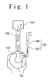
- Fig. 1 shows a two-stroke crosshead type diesel engine.
- the diesel engine includes a piston 101, a piston rod 102, a crosshead pin 103, and a telescopic tube 105.
- the piston rod 102 connects the piston 101 to the crosshead pin 103.
- the telescopic tube 105 includes an outer tube 106 and an inner tube 107. Concomitantly with a vertical motion of the piston 101, the crosshead pin 103 and the inner tube 107 move vertically, and the telescopic tube 105 is stretched and shrunk. Oil having flown from a space in the outer tube 106 through an opening formed at an upper end of the inner tube 107 into a space in the inner tube 107 is supplied to the piston 101 or a crosshead bearing 104.
- JU-A-Showa 62-98722 discloses a conventional telescopic tube.
- An objective of the present invention is to provide an oil supply tube which suppresses alternation of oil supply pressure.
- an oil supply tube includes: an outer tube which extends vertically; an inner tube which extends vertically; a first seal configured to seal between the outer tube and the inner tube.
- the inner tube moves vertically together with a crosshead of a crosshead type diesel engine with respect to the outer tube. Oil flows into an outer tube internal space upper than the first seal in the outer tube.
- the inner tube includes: an upper portion which is located upper than the first seal in the outer tube when the crosshead is at a bottom dead center position; and a lower portion which is located lower than the first seal when the crosshead is at a top dead center position.
- the lower portion is connected to an oil flow path provided in the crosshead. An upper end of the upper portion is closed.
- a first opening is formed in a side wall of the upper portion.
- a cross sectional area of a flow path connecting the outer tube internal space to an inner tube internal space in the inner tube is increased when the inner tube moves upward.
- the above oil supply tube further includes a second seal arranged upper than the first seal to seal between the outer tube and the inner tube.
- the outer tube internal space is located upper than the second seal.
- a second opening which is located lower than the first opening is formed in the side wall. The second seal is located lower than the first opening and the second opening when the crosshead is at the top dead center position. The second seal is located between the first opening and the second opening when the crosshead is at the bottom dead center position.
- the above oil supply tube further includes a second seal arranged upper than the first seal to seal between the outer tube and the inner tube.
- the outer tube internal space is located upper than the second seal.
- the first opening has an opening shape which is long in vertical direction. An opening area of a portion of the first opening upper than the second seal is increased when the inner tube moves upward.
- an oil supply tube includes: a fixed tube; a movable tube configured to move vertically together with a crosshead of a crosshead type diesel engine with respect to the fixed tube; a first seal; and a second seal.
- the fixed tube includes a fixed side tube which extends vertically.
- a first opening having an opening shape which is long in vertical direction is formed in the fixed side tube.
- the movable tube includes: a movable side tube which extends vertically; and a connecting tube.
- the movable side tube includes: an upper portion; a lower portion lower than the upper portion; and a middle portion between the upper portion and the lower portion.
- the connecting tube connects the middle portion to an oil flow path formed in the crosshead.
- the fixed side tube and the movable side tube form concentric tubes.
- the first seal is arranged upper than the first opening to seal between the upper portion and the fixed side tube.
- the second seal is arranged lower than the first opening to seal between the lower portion and the fixed side tube.
- the movable side tube is arranged inside the fixed side tube.
- the connecting tube extends through the first opening to connect the oil flow path to the middle portion.
- the movable side tube is arranged outside the fixed side tube.
- a second opening is formed in the middle portion to connect a space in the middle portion to a flow path in the connecting tube.
- the movable tube moves vertically with respect to the fixed tube in a state that the first opening and the second opening face each other.
- the above oil supply tube further includes an accumulator provided to the fixed tube or the movable tube.
- an oil supply tube which suppresses alternation of oil supply pressure.
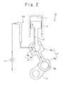
- the crosshead type diesel engine 10 is, for example, a marine two-cycle diesel engine.
- the crosshead type diesel engine 10 includes a cylinder 11, a piston 12, a piston rod 13, a crosshead 14, a connecting rod 15, a clank arm 16, a pump 17, and an oil supply tube 20A.
- the piston 12 is arranged in the cylinder 11.
- the piston rod 13 couples the piston 12 to the crosshead 14.
- the connecting rod 15 connects the crosshead 14 to the clank arm 16.
- the connecting rod 15 includes a bearing portion 15a which engages a pin 14a of the crosshead 14 and a bearing portion 15b which engages a pin 16a of the clank arm 16.
- the crosshead 14 moves reciprocally in vertical direction together with the piston 12, and the clank arm 16 rotates.
- the crosshead 14 is arranged at a top dead center position.
- the crosshead 14 is arranged at a bottom dead center position.
- the pump 17 supplies oil to an oil flow path 14b provided in the crosshead 14 via the oil supply tube 20A.
- the oil supplied to the oil flow path 14b cools the piston 12, lubricates between the pin 14a and the bearing portion 15a, or lubricates between the pin 16a and the bearing portion 15b.
- the oil supply tube 20A is stretched and shrunk in vertical direction.
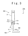
- the oil supply tube 20A includes a fixed tube 30A, a movable tube 40A, and a seal 51.
- the movable tube 40A moves vertically together with the crosshead 14 with respect to the fixed tube 30A.
- the fixed tube 30A includes an outer tube 31 which extends vertically.
- the movable tube 40A includes an inner tube 41 which extends vertically and a connecting tube 49A.
- the seal 51 seals between the outer tube 31 and the inner tube 41.
- the inner tube 41 includes an upper portion 41p which is located upper than the seal 51 in the outer tube 31 when the crosshead 14 is located at the bottom dead center position and a lower portion 41q which is located lower than the seal 51 when the crosshead is located at the top dead center position.
- the connecting tube 49A connects the lower portion 41q to the oil flow path 14b provided in the crosshead 14.
- the upper portion 41p includes a cylindrical portion 41r which forms a side wall of the upper portion 41p and an upper cap 41x which closes an upper end of the cylindrical portion 41r (an upper end of the upper portion 41p).
- the axis of the cylindrical portion 41r extends vertically.
- the upper cap 41x prevents oil from passing through the upper end of the cylindrical portion 41r in vertical direction.
- An opening 41a is formed in the cylindrical portion 41r. The opening 41a penetrates the cylindrical portion 41r in the radial direction.
- the oil pumped out from the pump 17 flows into an outer tube internal space 31a upper than the seal 51 in the outer tube 31 and then flows through the opening 41a into the inner tube 41. After flowing from the inner tube 41 through the connecting tube 49A into the oil flow path 14b, the oil cools the piston 12, lubricates between the pin 14a and the bearing portion 15a, or lubricates between the pin 16a and the bearing portion 15b.
- FIG. 4 an oil supply tube 20B according to a second embodiment of the present invention is described.
- the oil supply tube 20B is applied to the crosshead type diesel engine 10 in place of the oil supply tube 20A.
- Fig. 4 shows the oil supply tube 20B when the crosshead 14 is at the bottom dead center position.
- the oil supply tube 20B includes a fixed tube 30B, a movable tube 40B, a seal 52, and a seal 53.
- the movable tube 40B moves vertically together with the crosshead 14 with respect to the fixed tube 30B.
- the fixed tube 30B includes an outer tube 32 which extends vertically.
- the movable tube 40B includes an inner tube 42 which extends vertically and a connecting tube 49B.
- the seals 52 and 53 respectively seal between the outer tube 32 and the inner tube 42.
- the seal 52 is arranged upper than the seal 53.
- the inner tube 42 includes an upper portion 42p and a lower potion 42q lower than the upper portion 42p.
- the connecting tube 49B connects the lower portion 42q to the oil flow path 14b provided in the crosshead 14.
- the upper portion 42p is arranged in the outer tube 32 and moves vertically in the outer tube 32.
- the upper portion 42p includes a cylindrical portion 42r which forms a side wall of the upper portion 42p and an upper cap 42x which closes an upper end of the cylindrical portion 42r (an upper end of the upper portion 42p).
- the axis of the cylindrical portion 42r extends vertically.
- the upper cap 42x prevents oil from passing through the upper end of the cylindrical portion 42r in vertical direction.
- a plurality of openings 42a to 42c are formed in the cylindrical portion 42r.
- Fig. 4 shows an example in which the number of the openings 42a to 42c is three; however, the number of the openings 42a to 42c is not limited to three.
- Each of the openings 42a to 42c penetrates the cylindrical portion 42r in the radial direction.
- the opening 42b is located lower than the opening 42a, and the opening 42c is located lower than the opening 42b.
- the opening 42a is always located upper than the seal 52 to prevent oil supply from being interrupted even when the crosshead 14 is at the bottom dead center position.
- the upper portion 42p is located upper than the seal 53 and the seal 52 is located between the opening 42a and the opening 42b.
- a portion of the openings 42a to 42c upper than the seal 52 forms a flow path connecting an outer tube internal space 32a upper than the seal 52 in the outer tube 32 to a space in the inner tube 42.
- the opening area of the portion of the openings 42a to 42c upper than the seal 52 is increased when the movable tube 40B moves upward and is decreased when the movable tube 40B moves downward.
- the oil pumped out from the pump 17 flows into the outer tube internal space 32a and then flows into the inner tube 42 through the portion of the openings 42a to 42c upper than the seal 52. After flowing from the inner tube 42 through the connecting tube 49B into the oil flow path 14b, the oil cools the piston 12, lubricates between the pin 14a and the bearing portion 15a, or lubricates between the pin 16a and the bearing portion 15b.
- an effective height h of oil column is large when the crosshead 14 is at the bottom dead center position (see Fig. 4 ), and the height h is small when the crosshead 14 is at the top dead center position (see Fig. 5 ).
- the alternation of oil supply pressure due to the influence of oil column inertia is further suppressed.
- the cross sectional area of the flow path connecting the outer tube internal space 32a to the space in the inner tube 42 is increased when the movable tube 40B moves upward and is decreased when the movable tube 40B moves downward. Therefore, the effective flow path between the pump 17 and the oil flow path 14b becomes wider when the oil supply pressure is reduced due to the influence of oil column inertia, the effective flow path between the pump 17 and the oil flow path 14b becomes narrower when the oil supply pressure is elevated due to the influence of oil column inertia. As a result, the alternation of oil flow rate is suppressed.
- FIG. 6 an oil supply tube 20C according to a third embodiment of the present invention is described.
- the oil supply tube 20C is applied to the crosshead type diesel engine 10 in place of the oil supply tube 20A.
- Fig. 6 shows the oil supply tube 20C when the crosshead 14 is at the bottom dead center position.
- the oil supply tube 20C includes a fixed tube 30C, a movable tube 40C, a seal 54, and a seal 55.
- the movable tube 40C moves vertically together with the crosshead 14 with respect to the fixed tube 30C.
- the fixed tube 30C includes an outer tube 33 which extends vertically.
- the movable tube 40C includes an inner tube 43 which extends vertically and a connecting tube 49C.
- the seals 54 and 54 respectively seal between the outer tube 33 and the inner tube 43.
- the seal 54 is arranged upper than the seal 55.
- the inner tube 43 includes an upper portion 43p and a lower potion 43q lower than the upper portion 43p.
- the connecting tube 49C connects the lower portion 43q to the oil flow path 14b provided in the crosshead 14.
- the upper portion 43p is arranged in the outer tube 33 and moves vertically in the outer tube 33.
- the upper portion 43p includes a cylindrical portion 43r which forms a side wall of the upper portion 43p and an upper cap 43x which closes an upper end of the cylindrical portion 43r (an upper end of the upper portion 43p).
- the axis of the cylindrical portion 43r extends vertically.
- the upper cap 43x prevents oil from passing through the upper end of the cylindrical portion 43r in vertical direction.
- An opening 43a is formed in the cylindrical portion 43r.
- the opening 43a penetrates the cylindrical portion 43r in the radial direction.
- the opening 43a has an opening shape which is long in vertical direction.
- the upper portion 43p is located upper than the seal 55 and the seal 54 is located between the upper end and the lower end of the opening 43a. Namely, oil supply is prevented from being interrupted even when the crosshead 14 is at the bottom dead center position.
- a portion of the opening 43a upper than the seal 54 forms a flow path connecting an outer tube internal space 33a upper than the seal 54 in the outer tube 33 to a space in the inner tube 43.
- the opening area of the portion of the opening 43a upper than the seal 54 is increased when the movable tube 40C moves upward and is decreased when the movable tube 40C moves downward.
- the oil pumped out from the pump 17 flows into the outer tube internal space 33a and then flows into the inner tube 43 through the portion of the opening 43a upper than the seal 54. After flowing from the inner tube 43 through the connecting tube 49C into the oil flow path 14b, the oil cools the piston 12, lubricates between the pin 14a and the bearing portion 15a, or lubricates between the pin 16a and the bearing portion 15b.
- an oil supply tube 20D according to a third embodiment of the present invention is described.
- the oil supply tube 20D is applied to the crosshead type diesel engine 10 in place of the oil supply tube 20A.
- the oil supply tube 20D includes a fixed tube 30D, a movable tube 40D, a seal 56, and a seal 57.
- the movable tube 40D moves vertically together with the crosshead 14 with respect to the fixed tube 30D.
- the fixed tube 30D includes an outer cylinder 34 which extends vertically and a lower cap 35 which closes a lower end of the outer cylinder 34.
- the axis of the outer cylinder 34 extends vertically.
- An opening 34a is formed in the outer cylinder 34.
- the opening 34a has an opening shape which is long in vertical direction.
- the opening 34a penetrates the outer cylinder 34 in the radial direction.
- the movable tube 40D includes an inner cylinder 44 which extends vertically and a connecting tube 49D.
- the inner cylinder 44 is smaller than the outer cylinder 34 in diameter.
- the inner cylinder 44 is arranged inside the outer cylinder 34 such that the inner cylinder 44 and the outer cylinder 34 form concentric cylinders.
- the inner cylinder 44 includes an upper portion 44a, a lower portion 44b lower than the upper portion 44a, and a middle portion 44c between the upper portion 44a and the lower portion 44b.
- Each of the upper portion 44a, the lower portion 44b, and the middle portion 44c has a cylindrical shape of which an axis extends vertically. Since an upper end of the upper portion 44a is open, oil can pass the upper end in vertical direction. Since a lower end of the lower portion 44b is open, oil can pass the lower end in vertical direction.
- the seal 56 is arranged upper than the opening 34a to seal between the upper portion 44a and the outer cylinder 34.
- the seal 57 is arranged lower than the opening 34a and upper than the lower cap 35 to seal between the lower portion 44b and the outer cylinder 34.
- the connecting tube 49D extends through the opening 34a to connect the middle portion 44c to the oil flow path 14b.
- An outer cylinder internal space 34b upper than the seal 56 in the outer cylinder 34 and an outer cylinder internal space 34c lower than the seal 57 and upper than the lower cap 35 in the outer cylinder 34 are connected each other through an internal space of the inner cylinder 44.
- the oil pumped out from the pump 17 flows into the outer cylinder internal space 34b and then flows into the inner cylinder 44. After flowing from the inner cylinder 44 through the connecting tube 49D into the oil flow path 14b, the oil cools the piston 12, lubricates between the pin 14a and the bearing portion 15a, or lubricates between the pin 16a and the bearing portion 15b.
- the alternation of oil supply pressure is suppressed. Furthermore, since the oil column in the oil sully tube 20D does not move vertically when the movable tube 40D moves vertically, the alternation of oil supply pressure due to the influence of oil column inertia is suppressed.
- the outer cylinder 34 may be replaced by a tube having a cross section other than a circle.
- an oil supply tube 20E according to a fifth embodiment of the present invention is described.
- the oil supply tube 20E is applied to the crosshead type diesel engine 10 in place of the oil supply tube 20A.
- the oil supply tube 20E includes a fixed tube 30E, a movable tube 40E, a seal 58, and a seal 59.
- the movable tube 40E moves vertically together with the crosshead 14 with respect to the fixed tube 30E.
- the fixed tube 30E includes an inner cylinder 36 which extends vertically and a lower cap 37 which closes a lower end of the inner cylinder 36.
- the axis of the inner cylinder 36 extends vertically.
- An opening 36a is formed in the inner cylinder 36.
- the opening 36a has an opening shape which is long in vertical direction.
- the opening 36a penetrates the inner cylinder 36 in the radial direction.
- the movable tube 40E includes an outer cylinder 45 which extends vertically and a connecting tube 49E.
- the outer cylinder 45 is larger than the inner cylinder 36 in diameter.
- the outer cylinder 45 is arranged outside the inner cylinder 36 such that the outer cylinder 45 and the inner cylinder 36 form concentric cylinders.
- the outer cylinder 45 includes an upper portion 45a, a lower portion 45b lower than the upper portion 45a, and a middle portion 45c between the upper portion 45a and the lower portion 45b.
- Each of the upper portion 45a, the lower portion 45b, and the middle portion 45c has a cylindrical shape of which an axis extends vertically.
- the seal 58 is arranged upper than the opening 36a to seal between the upper portion 45a and the inner cylinder 36.
- the seal 59 is arranged lower than the opening 36a to seal between the lower portion 45b and the inner cylinder 36.
- the seals 58 and 59 can be foxed to any of the inner cylinder 36 and the outer cylinder 45.
- the connecting tube 49E connects the middle portion 45c to the oil flow path 14b.
- An opening 45d is formed in the middle portion 45c to connect a space in the middle portion 45c to a flow path in the connecting tube 49E. In a state that the opening 45d faces the opening 36a (in a state that the opening 45d and the opening 36a are overlapped), the movable tube 40E moves vertically with respect to the fixed tube 30E.
- the oil pumped out from the pump 17 flows into the inner cylinder 36 and then flows through the opening 36a and the opening 45d into the connecting tube 49E. After flowing through the connecting tube 49E into the oil flow path 14b, the oil cools the piston 12, lubricates between the pin 14a and the bearing portion 15a, or lubricates between the pin 16a and the bearing portion 15b.
- the alternation of oil supply pressure is suppressed. Furthermore, since the oil column in the oil sully tube 20E does not move vertically when the movable tube 40E moves vertically, the alternation of oil supply pressure due to the influence of oil column inertia is suppressed.
- the manufacture of the oil supply tube 20E according to the present embodiment is easier than that of the oil supply tube 20D. Since the outer cylinder 45 is easily separated from the inner cylinder 36, the maintenance of the oil supply tube 20E according to the present embodiment is easier than that of the oil supply tube 20D.
- the inner cylinder 36 may be replaced by a tube having a cross section other than a circle.
- the outer cylinder 45 may be replaced by a tube having a cross section other than a circle.
- an oil supply tube 20F according to a sixth embodiment of the present invention is described.
- the oil supply tube 20F is applied to the crosshead type diesel engine 10 in place of the oil supply tube 20A.
- the oil supply tube 20F includes the fixed tube 30D, the movable tube 40D, the seal 56, and the seal 57 which are described above.
- the oil supply tube 20F further includes an accumulator 60 provided to the fixed tube 30D.
- oil is supplemented by the accumulator 60.
- the accumulator 60 may be provided to the movable tube 40D (for example, the connecting tube 49D).
- a function similar to the accumulator 60 may be provided to the movable tube 40D by making a portion of the flow path of the movable tube 40D (for example, the connecting tube 49D) wider, for example.
- the accumulator 60 may be provided to the fixed tube 30E or the movable tube 40E of the oil supply tube 20E, or a function similar to the accumulator 60 may be provided to the movable tube 40E by making a portion of the flow path of the movable tube 40E (for example, the connection tube 49E) wider.
- the same modifications can be carried out for the oil supply tubes 20A, 20B, and 20C.
Landscapes
- Engineering & Computer Science (AREA)
- Mechanical Engineering (AREA)
- General Engineering & Computer Science (AREA)
- Chemical & Material Sciences (AREA)
- Combustion & Propulsion (AREA)
- Lubrication Of Internal Combustion Engines (AREA)
- Lubrication Details And Ventilation Of Internal Combustion Engines (AREA)
Abstract
Description
- The present invention relates to an oil supply tube for supplying oil to a crosshead of a crosshead type diesel engine.
-
Fig. 1 shows a two-stroke crosshead type diesel engine. The diesel engine includes apiston 101, apiston rod 102, acrosshead pin 103, and atelescopic tube 105. Thepiston rod 102 connects thepiston 101 to thecrosshead pin 103. Thetelescopic tube 105 includes anouter tube 106 and aninner tube 107. Concomitantly with a vertical motion of thepiston 101, thecrosshead pin 103 and theinner tube 107 move vertically, and thetelescopic tube 105 is stretched and shrunk. Oil having flown from a space in theouter tube 106 through an opening formed at an upper end of theinner tube 107 into a space in theinner tube 107 is supplied to thepiston 101 or a crosshead bearing 104. - In synchronization with stretch and shrink of the
telescopic tube 105, the volume of internal space of thetelescopic tube 105 is increased and decreased. Therefore, when thetelescopic tube 105 is stretched, pressure of the oil is reduced momentarily. Furthermore, since the oil moves vertically together with theinner tube 107, pressure of the oil alternates due to the influence of oil column inertia. Consequently, supply pressure of the oil is unstable. - Japanese Utility Model Publication (
JU-A-Showa 62-98722 -
- Patent Document 1: Japanese Utility Model Publication (
JU-A-Showa 62-98722 - An objective of the present invention is to provide an oil supply tube which suppresses alternation of oil supply pressure.
- In a first aspect of the present invention, an oil supply tube includes: an outer tube which extends vertically; an inner tube which extends vertically; a first seal configured to seal between the outer tube and the inner tube. The inner tube moves vertically together with a crosshead of a crosshead type diesel engine with respect to the outer tube. Oil flows into an outer tube internal space upper than the first seal in the outer tube. The inner tube includes: an upper portion which is located upper than the first seal in the outer tube when the crosshead is at a bottom dead center position; and a lower portion which is located lower than the first seal when the crosshead is at a top dead center position. The lower portion is connected to an oil flow path provided in the crosshead. An upper end of the upper portion is closed. A first opening is formed in a side wall of the upper portion.
- Since the upper end of the upper portion is closed, the head of oil column in the inner tube is held. Therefore, the alternation of oil supply pressure due to the influence of oil column inertia is suppressed.
- Preferably, a cross sectional area of a flow path connecting the outer tube internal space to an inner tube internal space in the inner tube is increased when the inner tube moves upward.
- Preferably, the above oil supply tube further includes a second seal arranged upper than the first seal to seal between the outer tube and the inner tube. The outer tube internal space is located upper than the second seal. Preferably, a second opening which is located lower than the first opening is formed in the side wall. The second seal is located lower than the first opening and the second opening when the crosshead is at the top dead center position. The second seal is located between the first opening and the second opening when the crosshead is at the bottom dead center position.
- Preferably, the above oil supply tube further includes a second seal arranged upper than the first seal to seal between the outer tube and the inner tube. The outer tube internal space is located upper than the second seal. Preferably, the first opening has an opening shape which is long in vertical direction. An opening area of a portion of the first opening upper than the second seal is increased when the inner tube moves upward.
- In a second aspect of the present invention, an oil supply tube includes: a fixed tube; a movable tube configured to move vertically together with a crosshead of a crosshead type diesel engine with respect to the fixed tube; a first seal; and a second seal. The fixed tube includes a fixed side tube which extends vertically. A first opening having an opening shape which is long in vertical direction is formed in the fixed side tube. The movable tube includes: a movable side tube which extends vertically; and a connecting tube. The movable side tube includes: an upper portion; a lower portion lower than the upper portion; and a middle portion between the upper portion and the lower portion. The connecting tube connects the middle portion to an oil flow path formed in the crosshead. The fixed side tube and the movable side tube form concentric tubes. The first seal is arranged upper than the first opening to seal between the upper portion and the fixed side tube. The second seal is arranged lower than the first opening to seal between the lower portion and the fixed side tube.
- Since the volume of internal space of the oil supply tube does not change when the movable tube moves vertically, the alternation of oil supply pressure is suppressed. Since the oil column in the oil sully tube does not move vertically when the movable tube moves vertically, the alternation of oil supply pressure due to the influence of oil column inertia is suppressed.
- Preferably, the movable side tube is arranged inside the fixed side tube. The connecting tube extends through the first opening to connect the oil flow path to the middle portion.
- Preferably, the movable side tube is arranged outside the fixed side tube. A second opening is formed in the middle portion to connect a space in the middle portion to a flow path in the connecting tube. The movable tube moves vertically with respect to the fixed tube in a state that the first opening and the second opening face each other.
- Preferably, the above oil supply tube further includes an accumulator provided to the fixed tube or the movable tube.
- According to the present invention, there is provided an oil supply tube which suppresses alternation of oil supply pressure.
- The above and other objects, advantages, and features of the present invention will be more apparent from the description of embodiments taken in conjunction with the accompanying drawings, in which:
-
Fig. 1 is a schematic diagram of a conventional crosshead type diesel engine; -
Fig. 2 is a schematic diagram of a diesel engine according to a first embodiment of the present invention; -
Fig. 3 is a sectional view of an oil supply tube according to the first embodiment; -
Fig. 4 is a sectional view of an oil supply tube according to a second embodiment of the present invention; -
Fig. 5 is a sectional view showing the oil supply tube according to the second embodiment when a piston is at the top dead center; -
Fig. 6 is a sectional view of an oil supply tube according to a third embodiment of the present invention; -
Fig. 7 is a sectional view showing the oil supply tube according to the third embodiment when the piston is at the top dead center; -
Fig. 8 is a sectional view of an oil supply tube according to a fourth embodiment of the present invention; -
Fig. 9 is a sectional view of an oil supply tube according to a fifth embodiment of the present invention; and -
Fig. 10 is a sectional view of an oil supply tube according to a sixth embodiment of the present invention. - With reference to the accompanying drawings, embodiments of an oil supply tube according to the present invention will be described below.
- With reference to
Fig. 2 , a crossheadtype diesel engine 10 according to a first embodiment of the present invention is described. The crossheadtype diesel engine 10 is, for example, a marine two-cycle diesel engine. The crossheadtype diesel engine 10 includes acylinder 11, a piston 12, apiston rod 13, acrosshead 14, a connectingrod 15, aclank arm 16, apump 17, and anoil supply tube 20A. The piston 12 is arranged in thecylinder 11. Thepiston rod 13 couples the piston 12 to thecrosshead 14. The connectingrod 15 connects thecrosshead 14 to theclank arm 16. The connectingrod 15 includes a bearingportion 15a which engages apin 14a of thecrosshead 14 and a bearingportion 15b which engages apin 16a of theclank arm 16. When the piston 12 moves reciprocally in vertical direction, thecrosshead 14 moves reciprocally in vertical direction together with the piston 12, and theclank arm 16 rotates. When the piston 12 is at the top dead center, thecrosshead 14 is arranged at a top dead center position. When the piston 12 is at the bottom dead center, thecrosshead 14 is arranged at a bottom dead center position. - The
pump 17 supplies oil to anoil flow path 14b provided in thecrosshead 14 via theoil supply tube 20A. The oil supplied to theoil flow path 14b cools the piston 12, lubricates between thepin 14a and the bearingportion 15a, or lubricates between thepin 16a and the bearingportion 15b. In order to supply oil to thecrosshead 14 moving reciprocally in vertical direction, theoil supply tube 20A is stretched and shrunk in vertical direction. - With reference to
Fig. 3 , theoil supply tube 20A is described. Theoil supply tube 20A includes a fixedtube 30A, amovable tube 40A, and aseal 51. Themovable tube 40A moves vertically together with thecrosshead 14 with respect to the fixedtube 30A. The fixedtube 30A includes anouter tube 31 which extends vertically. Themovable tube 40A includes aninner tube 41 which extends vertically and a connectingtube 49A. Theseal 51 seals between theouter tube 31 and theinner tube 41. Theinner tube 41 includes anupper portion 41p which is located upper than theseal 51 in theouter tube 31 when thecrosshead 14 is located at the bottom dead center position and a lower portion 41q which is located lower than theseal 51 when the crosshead is located at the top dead center position. The connectingtube 49A connects the lower portion 41q to theoil flow path 14b provided in thecrosshead 14. Theupper portion 41p includes acylindrical portion 41r which forms a side wall of theupper portion 41p and anupper cap 41x which closes an upper end of thecylindrical portion 41r (an upper end of theupper portion 41p). The axis of thecylindrical portion 41r extends vertically. Theupper cap 41x prevents oil from passing through the upper end of thecylindrical portion 41r in vertical direction. Anopening 41a is formed in thecylindrical portion 41r. Theopening 41a penetrates thecylindrical portion 41r in the radial direction. - The oil pumped out from the
pump 17 flows into an outer tubeinternal space 31a upper than theseal 51 in theouter tube 31 and then flows through theopening 41a into theinner tube 41. After flowing from theinner tube 41 through the connectingtube 49A into theoil flow path 14b, the oil cools the piston 12, lubricates between thepin 14a and the bearingportion 15a, or lubricates between thepin 16a and the bearingportion 15b. - According to the present embodiment, since the head of oil column in the
inner tube 41 is held by theupper cap 41x, the alternation of oil supply pressure due to the influence of oil column inertia is suppressed. - With reference to
Fig. 4 , anoil supply tube 20B according to a second embodiment of the present invention is described. Theoil supply tube 20B is applied to the crossheadtype diesel engine 10 in place of theoil supply tube 20A.Fig. 4 shows theoil supply tube 20B when thecrosshead 14 is at the bottom dead center position. - The
oil supply tube 20B includes a fixedtube 30B, amovable tube 40B, aseal 52, and aseal 53. Themovable tube 40B moves vertically together with thecrosshead 14 with respect to the fixedtube 30B. The fixedtube 30B includes anouter tube 32 which extends vertically. Themovable tube 40B includes aninner tube 42 which extends vertically and a connectingtube 49B. Theseals outer tube 32 and theinner tube 42. Theseal 52 is arranged upper than theseal 53. Theinner tube 42 includes anupper portion 42p and alower potion 42q lower than theupper portion 42p. The connectingtube 49B connects thelower portion 42q to theoil flow path 14b provided in thecrosshead 14. Theupper portion 42p is arranged in theouter tube 32 and moves vertically in theouter tube 32. Theupper portion 42p includes acylindrical portion 42r which forms a side wall of theupper portion 42p and anupper cap 42x which closes an upper end of thecylindrical portion 42r (an upper end of theupper portion 42p). The axis of thecylindrical portion 42r extends vertically. Theupper cap 42x prevents oil from passing through the upper end of thecylindrical portion 42r in vertical direction. A plurality ofopenings 42a to 42c are formed in thecylindrical portion 42r.Fig. 4 shows an example in which the number of theopenings 42a to 42c is three; however, the number of theopenings 42a to 42c is not limited to three. Each of theopenings 42a to 42c penetrates thecylindrical portion 42r in the radial direction. Theopening 42b is located lower than theopening 42a, and theopening 42c is located lower than theopening 42b. Theopening 42a is always located upper than theseal 52 to prevent oil supply from being interrupted even when thecrosshead 14 is at the bottom dead center position. - When the
crosshead 14 is at the bottom dead center position, theupper portion 42p is located upper than theseal 53 and theseal 52 is located between theopening 42a and theopening 42b. - With reference to
Fig. 5 , when thecrosshead 14 is at the top dead center position, theseal 52 is located lower than theopenings 42a to 42c and thelower portion 42q is located lower than theseal 53. - Therefore, a portion of the
openings 42a to 42c upper than theseal 52 forms a flow path connecting an outer tubeinternal space 32a upper than theseal 52 in theouter tube 32 to a space in theinner tube 42. The opening area of the portion of theopenings 42a to 42c upper than theseal 52 is increased when themovable tube 40B moves upward and is decreased when themovable tube 40B moves downward. - The oil pumped out from the
pump 17 flows into the outer tubeinternal space 32a and then flows into theinner tube 42 through the portion of theopenings 42a to 42c upper than theseal 52. After flowing from theinner tube 42 through the connectingtube 49B into theoil flow path 14b, the oil cools the piston 12, lubricates between thepin 14a and the bearingportion 15a, or lubricates between thepin 16a and the bearingportion 15b. - When the piston 12 is in the vicinity of the top dead center (when the
crosshead 14 is in the vicinity of the top dead center position), themovable tube 40B is accelerated downwardly. At this time, oil supply pressure is reduced due to the influence of oil column inertia. Whereas, when the piston 12 is in the vicinity of the bottom dead center (when thecrosshead 14 is in the vicinity of the bottom dead center position), themovable tube 40B is accelerated upwardly. At this time, oil supply pressure is elevated due to the influence of oil column inertia. - According to the present embodiment, since the head of oil column in the
inner tube 42 is held by theupper cap 42x, the alternation of oil supply pressure due to the influence of oil column inertia is suppressed. - According to the present embodiment, an effective height h of oil column is large when the
crosshead 14 is at the bottom dead center position (seeFig. 4 ), and the height h is small when thecrosshead 14 is at the top dead center position (seeFig. 5 ). Thus, the alternation of oil supply pressure due to the influence of oil column inertia is further suppressed. - Furthermore, according to the present embodiment, the cross sectional area of the flow path connecting the outer tube
internal space 32a to the space in theinner tube 42 is increased when themovable tube 40B moves upward and is decreased when themovable tube 40B moves downward. Therefore, the effective flow path between thepump 17 and theoil flow path 14b becomes wider when the oil supply pressure is reduced due to the influence of oil column inertia, the effective flow path between thepump 17 and theoil flow path 14b becomes narrower when the oil supply pressure is elevated due to the influence of oil column inertia. As a result, the alternation of oil flow rate is suppressed. - With reference to
Fig. 6 , an oil supply tube 20C according to a third embodiment of the present invention is described. The oil supply tube 20C is applied to the crossheadtype diesel engine 10 in place of theoil supply tube 20A.Fig. 6 shows the oil supply tube 20C when thecrosshead 14 is at the bottom dead center position. - The oil supply tube 20C includes a fixed
tube 30C, amovable tube 40C, aseal 54, and aseal 55. Themovable tube 40C moves vertically together with thecrosshead 14 with respect to the fixedtube 30C. The fixedtube 30C includes anouter tube 33 which extends vertically. Themovable tube 40C includes aninner tube 43 which extends vertically and a connectingtube 49C. Theseals outer tube 33 and theinner tube 43. Theseal 54 is arranged upper than theseal 55. Theinner tube 43 includes anupper portion 43p and alower potion 43q lower than theupper portion 43p. The connectingtube 49C connects thelower portion 43q to theoil flow path 14b provided in thecrosshead 14. Theupper portion 43p is arranged in theouter tube 33 and moves vertically in theouter tube 33. Theupper portion 43p includes acylindrical portion 43r which forms a side wall of theupper portion 43p and anupper cap 43x which closes an upper end of thecylindrical portion 43r (an upper end of theupper portion 43p). The axis of thecylindrical portion 43r extends vertically. Theupper cap 43x prevents oil from passing through the upper end of thecylindrical portion 43r in vertical direction. Anopening 43a is formed in thecylindrical portion 43r. Theopening 43a penetrates thecylindrical portion 43r in the radial direction. Theopening 43a has an opening shape which is long in vertical direction. - When the
crosshead 14 is at the bottom dead center position, theupper portion 43p is located upper than theseal 55 and theseal 54 is located between the upper end and the lower end of theopening 43a. Namely, oil supply is prevented from being interrupted even when thecrosshead 14 is at the bottom dead center position. - With reference to
Fig. 7 , when thecrosshead 14 is at the top dead center position, theseal 54 is located lower than the lower end of theopening 43a and thelower portion 43q is located lower than theseal 55. - Therefore, a portion of the
opening 43a upper than theseal 54 forms a flow path connecting an outer tubeinternal space 33a upper than theseal 54 in theouter tube 33 to a space in theinner tube 43. The opening area of the portion of theopening 43a upper than theseal 54 is increased when themovable tube 40C moves upward and is decreased when themovable tube 40C moves downward. - The oil pumped out from the
pump 17 flows into the outer tubeinternal space 33a and then flows into theinner tube 43 through the portion of theopening 43a upper than theseal 54. After flowing from theinner tube 43 through the connectingtube 49C into theoil flow path 14b, the oil cools the piston 12, lubricates between thepin 14a and the bearingportion 15a, or lubricates between thepin 16a and the bearingportion 15b. - According to the present invention, the same effects as those of the second embodiment are provided.
- With reference to
Fig. 8 , anoil supply tube 20D according to a third embodiment of the present invention is described. Theoil supply tube 20D is applied to the crossheadtype diesel engine 10 in place of theoil supply tube 20A. - The
oil supply tube 20D includes a fixedtube 30D, amovable tube 40D, aseal 56, and aseal 57. Themovable tube 40D moves vertically together with thecrosshead 14 with respect to the fixedtube 30D. The fixedtube 30D includes anouter cylinder 34 which extends vertically and alower cap 35 which closes a lower end of theouter cylinder 34. The axis of theouter cylinder 34 extends vertically. Anopening 34a is formed in theouter cylinder 34. Theopening 34a has an opening shape which is long in vertical direction. Theopening 34a penetrates theouter cylinder 34 in the radial direction. Themovable tube 40D includes aninner cylinder 44 which extends vertically and a connectingtube 49D. Theinner cylinder 44 is smaller than theouter cylinder 34 in diameter. Theinner cylinder 44 is arranged inside theouter cylinder 34 such that theinner cylinder 44 and theouter cylinder 34 form concentric cylinders. Theinner cylinder 44 includes anupper portion 44a, alower portion 44b lower than theupper portion 44a, and amiddle portion 44c between theupper portion 44a and thelower portion 44b. Each of theupper portion 44a, thelower portion 44b, and themiddle portion 44c has a cylindrical shape of which an axis extends vertically. Since an upper end of theupper portion 44a is open, oil can pass the upper end in vertical direction. Since a lower end of thelower portion 44b is open, oil can pass the lower end in vertical direction. Theseal 56 is arranged upper than theopening 34a to seal between theupper portion 44a and theouter cylinder 34. Theseal 57 is arranged lower than theopening 34a and upper than thelower cap 35 to seal between thelower portion 44b and theouter cylinder 34. The connectingtube 49D extends through theopening 34a to connect themiddle portion 44c to theoil flow path 14b. An outer cylinderinternal space 34b upper than theseal 56 in theouter cylinder 34 and an outer cylinderinternal space 34c lower than theseal 57 and upper than thelower cap 35 in theouter cylinder 34 are connected each other through an internal space of theinner cylinder 44. - The oil pumped out from the
pump 17 flows into the outer cylinderinternal space 34b and then flows into theinner cylinder 44. After flowing from theinner cylinder 44 through the connectingtube 49D into theoil flow path 14b, the oil cools the piston 12, lubricates between thepin 14a and the bearingportion 15a, or lubricates between thepin 16a and the bearingportion 15b. - According to the present embodiment, since the volume of internal space of the
oil supply tube 20D does not change when themovable tube 40D movers vertically, the alternation of oil supply pressure is suppressed. Furthermore, since the oil column in theoil sully tube 20D does not move vertically when themovable tube 40D moves vertically, the alternation of oil supply pressure due to the influence of oil column inertia is suppressed. - By the way, when the
seals outer cylinder 34, theouter cylinder 34 may be replaced by a tube having a cross section other than a circle. - With reference to
Fig. 9 , anoil supply tube 20E according to a fifth embodiment of the present invention is described. Theoil supply tube 20E is applied to the crossheadtype diesel engine 10 in place of theoil supply tube 20A. - The
oil supply tube 20E includes a fixedtube 30E, amovable tube 40E, aseal 58, and aseal 59. Themovable tube 40E moves vertically together with thecrosshead 14 with respect to the fixedtube 30E. The fixedtube 30E includes aninner cylinder 36 which extends vertically and alower cap 37 which closes a lower end of theinner cylinder 36. The axis of theinner cylinder 36 extends vertically. Anopening 36a is formed in theinner cylinder 36. Theopening 36a has an opening shape which is long in vertical direction. Theopening 36a penetrates theinner cylinder 36 in the radial direction. Themovable tube 40E includes anouter cylinder 45 which extends vertically and a connectingtube 49E. Theouter cylinder 45 is larger than theinner cylinder 36 in diameter. Theouter cylinder 45 is arranged outside theinner cylinder 36 such that theouter cylinder 45 and theinner cylinder 36 form concentric cylinders. Theouter cylinder 45 includes anupper portion 45a, alower portion 45b lower than theupper portion 45a, and amiddle portion 45c between theupper portion 45a and thelower portion 45b. Each of theupper portion 45a, thelower portion 45b, and themiddle portion 45c has a cylindrical shape of which an axis extends vertically. Theseal 58 is arranged upper than theopening 36a to seal between theupper portion 45a and theinner cylinder 36. Theseal 59 is arranged lower than theopening 36a to seal between thelower portion 45b and theinner cylinder 36. Theseals inner cylinder 36 and theouter cylinder 45. The connectingtube 49E connects themiddle portion 45c to theoil flow path 14b. Anopening 45d is formed in themiddle portion 45c to connect a space in themiddle portion 45c to a flow path in the connectingtube 49E. In a state that theopening 45d faces theopening 36a (in a state that theopening 45d and theopening 36a are overlapped), themovable tube 40E moves vertically with respect to the fixedtube 30E. - The oil pumped out from the
pump 17 flows into theinner cylinder 36 and then flows through theopening 36a and theopening 45d into the connectingtube 49E. After flowing through the connectingtube 49E into theoil flow path 14b, the oil cools the piston 12, lubricates between thepin 14a and the bearingportion 15a, or lubricates between thepin 16a and the bearingportion 15b. - According to the present embodiment, since the volume of internal space of the
oil supply tube 20E does not change when themovable tube 40E moves vertically, the alternation of oil supply pressure is suppressed. Furthermore, since the oil column in theoil sully tube 20E does not move vertically when themovable tube 40E moves vertically, the alternation of oil supply pressure due to the influence of oil column inertia is suppressed. - Furthermore, the manufacture of the
oil supply tube 20E according to the present embodiment is easier than that of theoil supply tube 20D. Since theouter cylinder 45 is easily separated from theinner cylinder 36, the maintenance of theoil supply tube 20E according to the present embodiment is easier than that of theoil supply tube 20D. - By the way, when the
seals inner cylinder 36, theinner cylinder 36 may be replaced by a tube having a cross section other than a circle. When theseals outer cylinder 45, theouter cylinder 45 may be replaced by a tube having a cross section other than a circle. - With reference to
Fig. 10 , anoil supply tube 20F according to a sixth embodiment of the present invention is described. Theoil supply tube 20F is applied to the crossheadtype diesel engine 10 in place of theoil supply tube 20A. - The
oil supply tube 20F includes the fixedtube 30D, themovable tube 40D, theseal 56, and theseal 57 which are described above. Theoil supply tube 20F further includes anaccumulator 60 provided to the fixedtube 30D. - According to the present embodiment, when a sudden shortage of oil occurs at a downstream such as the piston 12 and the bearing
portion 15a, oil is supplemented by theaccumulator 60. - By the way, the
accumulator 60 may be provided to themovable tube 40D (for example, the connectingtube 49D). When theaccumulator 60 is difficult to be attached externally to the fixedtube 30D or themovable tube 40D, a function similar to theaccumulator 60 may be provided to themovable tube 40D by making a portion of the flow path of themovable tube 40D (for example, the connectingtube 49D) wider, for example. - The present invention has been described with reference to the embodiments; however, the present invention is not limited to the above embodiments. Various modifications can be applied to the above embodiments. The above embodiments can be combined each other.
- For example, the
accumulator 60 may be provided to the fixedtube 30E or themovable tube 40E of theoil supply tube 20E, or a function similar to theaccumulator 60 may be provided to themovable tube 40E by making a portion of the flow path of themovable tube 40E (for example, theconnection tube 49E) wider. The same modifications can be carried out for theoil supply tubes
Claims (8)
- An oil supply tube comprising:an outer tube which extends vertically;an inner tube which extends vertically; anda first seal configured to seal between said outer tube and said inner tube,wherein said inner tube moves vertically together with a crosshead of a crosshead type diesel engine with respect to said outer tube,oil flows into an outer tube internal space upper than said first seal in said outer tube,said inner tube includes:an upper portion which is located upper than said first seal in said outer tube when said crosshead is at a bottom dead center position; anda lower portion which is located lower than said first seal when said crosshead is at a top dead center position,said lower portion is connected to an oil flow path provided in said crosshead,an upper end of said upper portion is closed, anda first opening is formed in a side wall of said upper portion.
- The oil supply tube according to claim 1, wherein a cross sectional area of a flow path connecting said outer tube internal space to an inner tube internal space in said inner tube is increased when said inner tube moves upward.
- The oil supply tube according to claim 1 or 2, further comprising a second seal arranged upper than said first seal to seal between said outer tube and said inner tube,
wherein said outer tube internal space is located upper than said second seal,
a second opening which is located lower than said first opening is formed in said side wall,
said second seal is located lower than said first opening and said second opening when said crosshead is at said top dead center position, and
said second seal is located between said first opening and said second opening when said crosshead is at said bottom dead center position. - The oil supply tube according to claim 1 or 2, further comprising a second seal arranged upper than said first seal to seal between said outer tube and said inner tube,
wherein said outer tube internal space is located upper than said second seal,
said first opening has an opening shape which is long in vertical direction, and
an opening area of a portion of said first opening upper than said second seal is increased when said inner tube moves upward. - An oil supply tube comprising:a fixed tube;a movable tube configured to move vertically together with a crosshead of a crosshead type diesel engine with respect to said fixed tube;a first seal; anda second seal,wherein said fixed tube includes a fixed side tube which extends vertically,a first opening having an opening shape which is long in vertical direction is formed in said fixed side tube,said movable tube includes:a movable side tube which extends vertically; anda connecting tube,said movable side tube includes:an upper portion;a lower portion lower than said upper portion; anda middle portion between said upper portion and said lower portion,said connecting tube connects said middle portion to an oil flow path formed in said crosshead,said fixed side tube and said movable side tube form concentric tubes,said first seal is arranged upper than said first opening to seal between said upper portion and said fixed side tube, andsaid second seal is arranged lower than said first opening to seal between said lower portion and said fixed side tube.
- The oil supply tube according to claim 5, wherein said movable side tube is arranged inside said fixed side tube, and
said connecting tube extends through said first opening to connect said oil flow path to said middle portion. - The oil supply tube according to claim 5, wherein said movable side tube is arranged outside said fixed side tube,
a second opening is formed in said middle portion to connect a space in said middle portion to a flow path in said connecting tube, and
said movable tube moves vertically with respect to said fixed tube in a state that said first opening and said second opening face each other. - The oil supply tube according to any of claims 5 to 7, further comprising an accumulator provided to said fixed tube or said movable tube.
Applications Claiming Priority (2)
| Application Number | Priority Date | Filing Date | Title |
|---|---|---|---|
| JP2009159162A JP5330911B2 (en) | 2009-07-03 | 2009-07-03 | Oil introduction pipe |
| PCT/JP2009/071600 WO2011001556A1 (en) | 2009-07-03 | 2009-12-25 | Oil duct |
Publications (2)
| Publication Number | Publication Date |
|---|---|
| EP2450537A1 true EP2450537A1 (en) | 2012-05-09 |
| EP2450537A4 EP2450537A4 (en) | 2016-01-20 |
Family
ID=43410650
Family Applications (1)
| Application Number | Title | Priority Date | Filing Date |
|---|---|---|---|
| EP09846847.3A Withdrawn EP2450537A4 (en) | 2009-07-03 | 2009-12-25 | Oil duct |
Country Status (5)
| Country | Link |
|---|---|
| EP (1) | EP2450537A4 (en) |
| JP (1) | JP5330911B2 (en) |
| KR (1) | KR101349421B1 (en) |
| CN (2) | CN103925038B (en) |
| WO (1) | WO2011001556A1 (en) |
Cited By (1)
| Publication number | Priority date | Publication date | Assignee | Title |
|---|---|---|---|---|
| DK202270305A1 (en) * | 2022-06-10 | 2024-01-09 | Man Energy Solutions Filial Af Man Energy Solutions Se Tyskland | Large turbocharged two-stroke internal combustion engine with improved piston cooling |
Families Citing this family (1)
| Publication number | Priority date | Publication date | Assignee | Title |
|---|---|---|---|---|
| JP5330911B2 (en) * | 2009-07-03 | 2013-10-30 | 三菱重工業株式会社 | Oil introduction pipe |
Family Cites Families (13)
| Publication number | Priority date | Publication date | Assignee | Title |
|---|---|---|---|---|
| US1928033A (en) * | 1930-07-04 | 1933-09-26 | Sulzer Ag | Cooling apparatus for reciprocating pistons |
| GB503007A (en) * | 1937-10-18 | 1939-03-29 | Sulzer Ag | Improvements in or relating to reciprocating engines having a crosshead between a piston rod and a connecting rod |
| DK167076B1 (en) * | 1991-03-26 | 1993-08-23 | Man B & W Diesel Gmbh | CROSS HEAD AND Piston rod for a stamp motor |
| JPH06298722A (en) | 1993-02-19 | 1994-10-25 | Taisho Pharmaceut Co Ltd | 5-Aminoacetylaminosulfone anilide compound |
| JPH0783015A (en) * | 1993-09-10 | 1995-03-28 | Mitsubishi Heavy Ind Ltd | Piston linkage type lubricator |
| JP3371727B2 (en) * | 1996-12-20 | 2003-01-27 | スズキ株式会社 | Oil supply structure of chain adjuster |
| JPH1151272A (en) * | 1997-07-31 | 1999-02-26 | Mitsubishi Heavy Ind Ltd | Expansion joint |
| JP2000087715A (en) * | 1998-09-10 | 2000-03-28 | Mitsubishi Heavy Ind Ltd | Piston cooling oil supply device for internal combustion engine |
| AU2993800A (en) * | 1999-03-11 | 2000-09-28 | Outboard Marine Corporation | Oil injection system |
| DE19914361C2 (en) * | 1999-03-30 | 2001-04-05 | Man B & W Diesel As Kopenhagen | Reciprocating internal combustion engine |
| FI114562B (en) * | 2001-10-09 | 2004-11-15 | Waertsilae Finland Oy | Arrangement and procedure for a diesel engine |
| CN2866863Y (en) * | 2005-11-11 | 2007-02-07 | 潍柴动力股份有限公司 | Diesel engine cylinder head and oil feed pipe connecting apparatus |
| JP5330911B2 (en) * | 2009-07-03 | 2013-10-30 | 三菱重工業株式会社 | Oil introduction pipe |
-
2009
- 2009-07-03 JP JP2009159162A patent/JP5330911B2/en not_active Expired - Fee Related
- 2009-12-25 CN CN201410111208.0A patent/CN103925038B/en not_active Expired - Fee Related
- 2009-12-25 EP EP09846847.3A patent/EP2450537A4/en not_active Withdrawn
- 2009-12-25 CN CN200980159129.4A patent/CN102421995B/en not_active Expired - Fee Related
- 2009-12-25 WO PCT/JP2009/071600 patent/WO2011001556A1/en not_active Ceased
- 2009-12-25 KR KR1020117026633A patent/KR101349421B1/en not_active Expired - Fee Related
Non-Patent Citations (1)
| Title |
|---|
| See references of WO2011001556A1 * |
Cited By (2)
| Publication number | Priority date | Publication date | Assignee | Title |
|---|---|---|---|---|
| DK202270305A1 (en) * | 2022-06-10 | 2024-01-09 | Man Energy Solutions Filial Af Man Energy Solutions Se Tyskland | Large turbocharged two-stroke internal combustion engine with improved piston cooling |
| DK181438B1 (en) * | 2022-06-10 | 2024-01-09 | Man Energy Solutions Filial Af Man Energy Solutions Se Tyskland | Large turbocharged two-stroke internal combustion engine with improved piston cooling |
Also Published As
| Publication number | Publication date |
|---|---|
| KR20120010258A (en) | 2012-02-02 |
| CN103925038A (en) | 2014-07-16 |
| CN102421995B (en) | 2014-04-16 |
| CN103925038B (en) | 2017-03-01 |
| JP5330911B2 (en) | 2013-10-30 |
| KR101349421B1 (en) | 2014-01-08 |
| EP2450537A4 (en) | 2016-01-20 |
| WO2011001556A1 (en) | 2011-01-06 |
| JP2011012639A (en) | 2011-01-20 |
| CN102421995A (en) | 2012-04-18 |
Similar Documents
| Publication | Publication Date | Title |
|---|---|---|
| US11220938B2 (en) | Device for lubricating a big-end bearing | |
| KR101349421B1 (en) | Oil duct | |
| JP6477387B2 (en) | Multi-link type piston-crank mechanism lubrication structure | |
| JP2018080668A (en) | Internal combustion engine | |
| US8667946B2 (en) | Multi-cylinder engine having communicating passages between cylinder bores | |
| JP2005331056A (en) | Engine bearing lubrication structure | |
| EP2751396B1 (en) | Lubrication arrangement | |
| JP5535683B2 (en) | Main bearing of internal combustion engine | |
| JP2008232079A (en) | Cylinder block of internal-combustion engine and method of manufacturing the cylinder block | |
| JP6673735B2 (en) | Piston for internal combustion engine | |
| JP7421854B2 (en) | engine | |
| JP2011069318A (en) | Oil supply pipe, crosshead pin, crosshead diesel engine provided therewith, and ship provided with crosshead diesel engine | |
| JP2580164Y2 (en) | Two-stroke engine piston | |
| CN2804501Y (en) | Piston rod and connecting.rod assembly for engine | |
| CN201636329U (en) | Novel balance cylinder copper sleeve lubrication sealing device | |
| KR20070120039A (en) | Cylinder liner device | |
| JP2006070795A (en) | Internal combustion engine | |
| JP2010112352A (en) | Internal combustion engine | |
| EP2133533A1 (en) | Piston cooling structure | |
| US20230067611A1 (en) | Piston for an internal combustion engine | |
| JP2005090322A (en) | Engine breather equipment | |
| WO2014057160A1 (en) | A piston for an internal combustion engine | |
| JP2008286161A (en) | Cylinder block | |
| JP5541453B2 (en) | diesel engine | |
| KR20170109888A (en) | Cylinder liner and cylinder block having the same |
Legal Events
| Date | Code | Title | Description |
|---|---|---|---|
| PUAI | Public reference made under article 153(3) epc to a published international application that has entered the european phase |
Free format text: ORIGINAL CODE: 0009012 |
|
| 17P | Request for examination filed |
Effective date: 20111025 |
|
| AK | Designated contracting states |
Kind code of ref document: A1 Designated state(s): AT BE BG CH CY CZ DE DK EE ES FI FR GB GR HR HU IE IS IT LI LT LU LV MC MK MT NL NO PL PT RO SE SI SK SM TR |
|
| DAX | Request for extension of the european patent (deleted) | ||
| RA4 | Supplementary search report drawn up and despatched (corrected) |
Effective date: 20151223 |
|
| RIC1 | Information provided on ipc code assigned before grant |
Ipc: F01M 1/06 20060101ALI20151217BHEP Ipc: F01M 11/02 20060101AFI20151217BHEP Ipc: F01P 3/10 20060101ALI20151217BHEP |
|
| STAA | Information on the status of an ep patent application or granted ep patent |
Free format text: STATUS: THE APPLICATION IS DEEMED TO BE WITHDRAWN |
|
| 18D | Application deemed to be withdrawn |
Effective date: 20160722 |