EP2450488A2 - Versenkbarer Mast für Absperrvorrichtungen - Google Patents
Versenkbarer Mast für Absperrvorrichtungen Download PDFInfo
- Publication number
- EP2450488A2 EP2450488A2 EP11405351A EP11405351A EP2450488A2 EP 2450488 A2 EP2450488 A2 EP 2450488A2 EP 11405351 A EP11405351 A EP 11405351A EP 11405351 A EP11405351 A EP 11405351A EP 2450488 A2 EP2450488 A2 EP 2450488A2
- Authority
- EP
- European Patent Office
- Prior art keywords
- fixed element
- sliding element
- sliding
- retractable mast
- fixed
- Prior art date
- Legal status (The legal status is an assumption and is not a legal conclusion. Google has not performed a legal analysis and makes no representation as to the accuracy of the status listed.)
- Granted
Links
Images


Classifications
-
- E—FIXED CONSTRUCTIONS
- E01—CONSTRUCTION OF ROADS, RAILWAYS, OR BRIDGES
- E01F—ADDITIONAL WORK, SUCH AS EQUIPPING ROADS OR THE CONSTRUCTION OF PLATFORMS, HELICOPTER LANDING STAGES, SIGNS, SNOW FENCES, OR THE LIKE
- E01F13/00—Arrangements for obstructing or restricting traffic, e.g. gates, barricades ; Preventing passage of vehicles of selected category or dimensions
- E01F13/04—Arrangements for obstructing or restricting traffic, e.g. gates, barricades ; Preventing passage of vehicles of selected category or dimensions movable to allow or prevent passage
- E01F13/044—Arrangements for obstructing or restricting traffic, e.g. gates, barricades ; Preventing passage of vehicles of selected category or dimensions movable to allow or prevent passage the barrier being formed by obstructing members situated on, flush with, or below the traffic surface, e.g. with inflatable members on the surface
- E01F13/046—Arrangements for obstructing or restricting traffic, e.g. gates, barricades ; Preventing passage of vehicles of selected category or dimensions movable to allow or prevent passage the barrier being formed by obstructing members situated on, flush with, or below the traffic surface, e.g. with inflatable members on the surface the obstructing members moving up in a translatory motion, e.g. telescopic barrier posts
Definitions
- the present invention relates to the field of masts for barriers and in general to retractable masts, able to be used for permitting or preventing the access to public or private places.
- the conventional masts for barriers are made of the most rigid materials, such as cement, steel, stone or wood; their cross-section can be round or cornered, more rarely also of other shapes.
- These masts are rigid, made of a single piece, and, if necessary, they must be completely extracted from the anchorage to the ground.
- Retractable masts are also known, and they solve many barrier problems. They are suitable for roads and squares which are freed from traffic only for limited periods of time, pedestrian areas, market squares, parking areas, garage entrances, arched gates, etc. They can be positioned in indoor or outdoor spaces and they can serve as boundary poles, barrier shafts, or as mast for barriers with ropes, bands or similar.
- the retractable masts comprise two main elongated and hollow elements, the one sliding with respect to the other.
- one of the two elements is anchored to the ground, and the other one slides from a retracted or underground position and an extracted or raised position with respect to the other element.
- a space or gap is present.
- Such devices are for example described in US 6,345,930 B1 and in GB 2210091A .
- US 6,345,930 B1 describes a retractable column with a simple structure, made of stainless steel.
- This column is generally of a cylindrical shape and, when in a lowered position it is housed within a sleeve under the ground level. In an active position, the column can be grasped with a handle and manually drawn until only a lower portion is underground.
- the lower portion of the cylindrical column has a spiral groove, cooperating with spiral grooves present on the upper portion of the sleeve, when the little mast is turned and raised towards a suitable point.
- the column has a safety lock, in order to permit to the little mast to be raised from a lowered position to an active position, and a double block, preventing an easy lowering of the same by malicious people.
- GB 2210091 describes a traffic column made of a base, positioned in a hole in the ground and supporting in a telescopic way a retractable and extendable element.
- the element can be fully retracted in the ground, or raised and positioned in a raised position with respect to the base, by means of a pin and of at least one groove cooperating with the base.
- the two main elements of the mast have a mutual space or gap.
- This aspect from one hand permits an easy and smooth mutual sliding of the two elements, and on the other hand it leads to problems of water infiltration, when such masts are generally positioned in outdoor places and environments, which are exposed to the weather. Such water or moisture infiltrations cause the formation of rust, and facilitate the corrosion, leading to a rapid decay, deterioration and aging of the portions forming the retractable mast. This makes frequent and expensive maintenance and repairing operations necessary. This leads to a reduction of the useful life of the mast, which then must necessarily be substituted at rather regular and short time intervals.
- the Applicant has found that, by adopting a space of small and reduced dimensions among the mutually sliding portions of the mast and by applying at the same time a watertight device, suitably sized and positioned, it is possible to maintain a simple and smooth sliding between the parts, by preventing at the same time the penetration of water and moisture and also of other liquids into the mast.
- the invention relates to a retractable mast for barriers, comprising:
- the retractable mast also has a watertight device and a radial distance less than 5 mm between the fixed element and the sliding element.
- the present invention in the aforesaid aspect, can have at least one of the preferred features later described.
- said average radial distance is less than 2 mm.
- said sliding element has at least one relief valve, in order to permit the exit of air during the sliding of said sliding element from said second position to said first position. This permits a translating movement of the element, which is simple, linear and without interruptions, with a minimum energy consumption.
- said fixed element has a duct, connecting the space with the outside of said fixed element. This permits to obtain a suitable evacuation of the air towards the outside of the mast.
- said relief valve is positioned in the upper part of the sliding element, for more than 50% of its total extension.
- said sealing device has at least two sealing elements, placed in the upper end of said fixed element and spaced apart in the direction of the longitudinal axis. This has the advantage to further increase the sealing of the device.
- said fixed element has at least two housings for said at least two sealing elements.
- said sliding element has at least one widened cross-sectional portion, placed in its lower part. This choice permits to further reduce the space between the sliding element and the fixed element, so assuring a safe blocking of the sliding element in the extracted position.
- said radial distance (R) is less than 1 mm.
- said sliding element has, at its upper part, a first flared portion, able to cooperate with a second flared portion, corresponding to the fixed element in said first position, so that said average distal length is less than 1,5 mm.
- the advantage of this preferred embodiment is to permit a good blocking of the elements in the lowered position, in particular when the sliding element is completely housed inside the fixed element. At the same time a perfect levelling of the mast with the ground is obtained.
- said fixed element has at least one external coating element. This permits to further protect the mast from external agents in order to use the same in any kind of ground.
- said retractable mast has a second device, interposed between said external coating element and said fixed element.
- said sliding element has a handle at its upper part, able to be manually grasped, in order to translate said sliding element with respect to said fixed element.
- a retractable mast for barriers is identified with the numeral reference 1.
- the retractable mast 1 for barriers according to the present invention has:
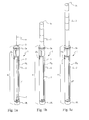
- the fixed element 2 extends along a longitudinal axis a, for a total extension E.
- the fixed element 2 and the sliding element 3 are coupled in such a way that the sliding element 3 can translate inside the fixed element 2 along the longitudinal axis a, from a first position p1, shown in figure 1 , in which it is housed in the fixed element 2, to a second position p2, shown in figure 1 c , in which it is extracted from the fixed element 2.
- the sliding element 3 is housed in the fixed element 2, for a portion equal to at least 70% of its total extension E. Still more preferably, as shown in Fig.1 a , in the first position p1 the sliding element 3 is completely housed in the fixed element 2 in order not to protrude with respect to the latter.
- the sliding element 3 in the second position p2 the sliding element 3 axially protrudes with respect to the fixed element 2 for a portion equal at least to 80% of its total extension.
- the sliding element 3 has at least one groove 5
- the sliding element 3 has at least a guide pin 7, cooperating with the groove 5.
- the groove 5 has at least two branches D1, D2, one branch D2 of the two branches D1, D2 being shorter than the other branch D1.
- the different extension of the two branches D1 and D2 permits to fix the sliding element in a first position p1 and in a second position p2.
- the sliding element 3 when the guide pin 7 engages with the branch D2 and rests on its bottom as in fig.1a , the sliding element 3 is in the first position p1, and alternatively when the guide pin 7 is rotated and engages with the branch 2 and rests on its bottom, the sliding element 3 is in the second position p2.
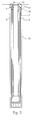
- the fixed element 2 as it is better shown in figure 2 , is also placed with respect to the sliding element 3, in order to form a gap between the two elements, substantially for the entire extension E of the fixed element 2.
- the gap I is defined by an average radial distance R between the fixed element 2 and the sliding element 3, in particular between the inner surface of the fixed element 2 and the outer surface of the sliding element 3.
- the arithmetic distance must be understood between the inner surface of the fixed element 2 and the outer surface of the sliding element 3 when varying the extension of the fixed element in a position p1, each distance being measured in a plane orthogonal to the axis a.
- the average radial distance R is less than 5 mm and the retractable mast 1 has at least one sealing device 15 interposed between the fixed element 2 and the sliding element 3.
- the average radial distance R is less to 2 mm.
- the fixed element 2 and the sliding element 3 have a cross-section, transversal to the substantially circumferential axis a and the gap has a cross-section substantially with a circumferential ring.
- the sliding element 3 has at its upper flared part 3s a first flared portion 16, able to cooperate with a second flared portion 17 corresponding to the fixed element 2, at the first position p1.
- a similar choice permits a good blocking of the sliding and fixed elements in the lowered position, in particular when the sliding element is completely housed in the fixed element. At the same time, a perfect levelling of the mast with the ground is obtained.
- the first flared portion 16 can cooperate with the second flared portion 17, so that the average radial distance R of such length is less than 1,5 mm and so consistently reduces the possibility of liquids entering into the gap I.
- the sliding element 3 has at least one portion 18 with a widened lateral portion, at its lower part 3i.
- the portion 18 with the widened lateral portion permits to block the extraction of the sliding element 3 with respect to the fixed one 2, in particular when the first one has reached the first position p1 shown in figure 1 c.
- This choice permits to further reduce the space between the sliding element and the fixed element, so assuring a safe blocking of the sliding element in the extracted position.
- said average radial distance R is less than 1 mm.
- the portion 18 with a widened transversal section is placed at approximately 1/5 of the total extension L of the sliding element 3, starting from its lower end 3i.
- the sliding element 3 has a second portion 19 with a widened transversal portion, spaced from the portion 18 and placed at its lower end 3i.
- the sliding element 3 Apart from the flared portion 16 and the portions 18,19 with a widened transversal section, the sliding element 3 has a substantially constant section.
- the sliding element 3 in order to permit the exit of air during the sliding of the sliding element 3 from the second position p2 to the first position p1, and consequently a smooth mutual sliding of the two elements 2,3 the sliding element 3 has at least one relief valve 20.
- the relief valve 20 is placed in the upper part of the sliding element 3, for up to 50% of its total extension L.
- the relief valve 20 connects the inside of the sliding element 3 with the gap I whereas a duct 21, provided on the fixed element 2 connects the gap I with the outside of the fixed element 2.
- the sealing device 15 is provided at the upper end 3s of the fixed element 2.
- the sealing device 15 has at least two sealing elements 15', 15" placed at the upper end 3s of the fixed element 2 and axially spaced in the direction of the longitudinal axis a.
- the sealing elements 15',15" made of a waterproof material seal the gap I between the fixed element 2 and the sliding element 3, while permitting the sliding of the element 3 with respect to the fixed element 2.
- the sealing elements 15', 15" have an annular extension around the sliding element 3 and are concentrically placed and axially spaced along the axis a of the fixed element 2.
- the fixed element 2 has at least two housings 22', 22" for the two sealing elements 15', 15"
- the two housings 22', 22" are spaced and placed along the axis a.
- the two housings 22', 22" face the gap I between the fixed element 2 and the sliding element 3.
- the fixed element 2 has at least one external coating element 23, made of plastic, able to isolate and protect the fixed element 2 from water or other liquids.
- the external coating element 23 has a cylindrical extension, but preferably it does not extend along the entire fixed element 2, but only of one portion of same, for example approximately 90% of its total extension E.
- the retractable mast 1 has a second sealing device 24 interposed between said external coating element 23 and said fixed element 2.
- the second sealing element 24 is placed at the upper interface between the external coating element 23 and the fixed element 2.
- the sliding element 3 has a handle 25 at its upper portion 3s and in particular at the upper end of the latter.
- the handle can be grasped manually, in order to translate the sliding element 3 with respect to the fixed element 2.
- the handle 25 can rotate between a closed position in which it disappears in a cavity made in the upper portion 3s of the sliding element 3, and an extracted position in which it substantially arises parallel to the axis a.
- the upper portion 3 of the fixed element 3 is made of two bodies 26, 27 mutually bound by means of a thread 28.
- a sealing element 29 is placed between the bodies 26,27.
Landscapes
- Engineering & Computer Science (AREA)
- Architecture (AREA)
- Civil Engineering (AREA)
- Structural Engineering (AREA)
- Refuge Islands, Traffic Blockers, Or Guard Fence (AREA)
- Specific Sealing Or Ventilating Devices For Doors And Windows (AREA)
- Train Traffic Observation, Control, And Security (AREA)
- Forklifts And Lifting Vehicles (AREA)
- Sliding Valves (AREA)
Applications Claiming Priority (1)
| Application Number | Priority Date | Filing Date | Title |
|---|---|---|---|
| CH01855/10A CH704056B1 (it) | 2010-11-05 | 2010-11-05 | Palo a scomparsa per sbarramenti. |
Publications (3)
| Publication Number | Publication Date |
|---|---|
| EP2450488A2 true EP2450488A2 (de) | 2012-05-09 |
| EP2450488A3 EP2450488A3 (de) | 2016-08-31 |
| EP2450488B1 EP2450488B1 (de) | 2021-07-07 |
Family
ID=45218613
Family Applications (1)
| Application Number | Title | Priority Date | Filing Date |
|---|---|---|---|
| EP11405351.5A Active EP2450488B1 (de) | 2010-11-05 | 2011-11-03 | Versenkbarer Mast für Absperrvorrichtungen |
Country Status (2)
| Country | Link |
|---|---|
| EP (1) | EP2450488B1 (de) |
| CH (1) | CH704056B1 (de) |
Cited By (2)
| Publication number | Priority date | Publication date | Assignee | Title |
|---|---|---|---|---|
| NL2008940C2 (nl) * | 2012-06-05 | 2013-12-09 | Vcp Streetcare B V | Zuilstelsel en zuil. |
| JP2015151812A (ja) * | 2014-02-18 | 2015-08-24 | 株式会社大畠製作所 | 駐車ポール |
Citations (2)
| Publication number | Priority date | Publication date | Assignee | Title |
|---|---|---|---|---|
| GB2210091A (en) | 1987-09-21 | 1989-06-01 | Eric Claud Bailey | Traffic bollard |
| US6345930B1 (en) | 2000-03-30 | 2002-02-12 | Parvis Mohassel | Manually operable retractable bollard |
Family Cites Families (16)
| Publication number | Priority date | Publication date | Assignee | Title |
|---|---|---|---|---|
| US3086430A (en) * | 1959-01-28 | 1963-04-23 | David T Emmel | Traffic control equipment |
| FR1335604A (fr) * | 1962-07-11 | 1963-08-23 | Mât télescopique | |
| CA2088513C (en) * | 1990-08-06 | 2001-04-03 | David H. Roper | Pop-up traffic control device |
| US5481828A (en) * | 1994-10-03 | 1996-01-09 | Kentrotas; Andreas | Security post for automobiles |
| US5683176A (en) * | 1995-04-07 | 1997-11-04 | Clendenin; Patrick B. | Retractable lighting assembly |
| DE19643815C1 (de) * | 1996-10-30 | 1997-11-20 | Butting H Gmbh & Co Kg | Absperrvorrichtung für Verkehrsflächen |
| GB2323617A (en) * | 1997-03-04 | 1998-09-30 | Graphic Precision Engineering | Telescopic Post |
| DE29901108U1 (de) * | 1999-01-23 | 1999-10-14 | Schroif, Heinz, Dipl.-Designer, 52076 Aachen | Versenkbarer Absperrpoller |
| GB2346640B (en) * | 1999-02-10 | 2003-05-21 | George James Wyers | Extendible posts |
| US6626606B1 (en) * | 2000-08-04 | 2003-09-30 | National Sign & Signal Co. | Retractable pylon arrangement |
| US7101112B2 (en) * | 2004-04-27 | 2006-09-05 | Robert Burns | Security barrier |
| NL1028889C1 (nl) * | 2005-04-28 | 2006-10-31 | Producon C V | Inrichting voor het beveiligen van machines en werktuigen tegen aanrijden door interne transportmiddelen (karren, wagens, etc.) en voor het geleiden van interne transportmiddelen (karren, stapels kratten op dolly's, etc.) in een sanitaire en stootvaste uitvoering. |
| US7244075B2 (en) * | 2005-08-04 | 2007-07-17 | Stadler David M | Telescoping bollard with screw drive |
| US7367746B2 (en) * | 2005-09-28 | 2008-05-06 | Koei Industry Co., Ltd. | Lifting pole apparatus for traffic control |
| US7481599B2 (en) * | 2006-05-04 | 2009-01-27 | Stice David L | Bollard type barrier assembly |
| CH700820B1 (de) * | 2007-06-01 | 2010-10-29 | Luca Rogantini | Versenkbarer Pfosten. |
-
2010
- 2010-11-05 CH CH01855/10A patent/CH704056B1/it not_active IP Right Cessation
-
2011
- 2011-11-03 EP EP11405351.5A patent/EP2450488B1/de active Active
Patent Citations (2)
| Publication number | Priority date | Publication date | Assignee | Title |
|---|---|---|---|---|
| GB2210091A (en) | 1987-09-21 | 1989-06-01 | Eric Claud Bailey | Traffic bollard |
| US6345930B1 (en) | 2000-03-30 | 2002-02-12 | Parvis Mohassel | Manually operable retractable bollard |
Cited By (2)
| Publication number | Priority date | Publication date | Assignee | Title |
|---|---|---|---|---|
| NL2008940C2 (nl) * | 2012-06-05 | 2013-12-09 | Vcp Streetcare B V | Zuilstelsel en zuil. |
| JP2015151812A (ja) * | 2014-02-18 | 2015-08-24 | 株式会社大畠製作所 | 駐車ポール |
Also Published As
| Publication number | Publication date |
|---|---|
| EP2450488B1 (de) | 2021-07-07 |
| EP2450488A3 (de) | 2016-08-31 |
| CH704056B1 (it) | 2014-07-15 |
| CH704056A1 (it) | 2012-05-15 |
Similar Documents
| Publication | Publication Date | Title |
|---|---|---|
| ES2688735T3 (es) | Pilote, cabeza de pilote y conector asociado | |
| US9752342B2 (en) | Flood protection for underground air vents | |
| US20130209173A1 (en) | Floodgate | |
| EP2450488B1 (de) | Versenkbarer Mast für Absperrvorrichtungen | |
| AU2012202022A1 (en) | Modular Pedestrian Tunnel | |
| CA2228729A1 (en) | Extendible safety posts for manhole ladders | |
| KR20060118991A (ko) | 신축성 가로등주 | |
| ES2266109T3 (es) | Mastil de perforacion con tornillo de banco de desenroscado movil y fijo. | |
| KR100801918B1 (ko) | 파고라 시설물 | |
| DE19955052A1 (de) | Sicherungssystem, insbesondere für Abstellplätze von Kraftfahrzeugen | |
| CN109057511B (zh) | 一种户外抗风设备 | |
| KR101121054B1 (ko) | 심재 보강 원주목 | |
| US6421845B1 (en) | Below-deck solar blanket roller assembly | |
| KR101640347B1 (ko) | 가로등 및 전신주 지주용 보강구조체 | |
| ES2795001T3 (es) | Sistema de cubierta de piscina | |
| CN211421155U (zh) | 一种土建施工用桩基辅助台 | |
| FR2782531A1 (fr) | Batiment a usage d'habitation comportant une piscine convertible | |
| KR200392021Y1 (ko) | 신축성 가로등주 | |
| CN203213703U (zh) | 一种电气设备检修围栏用栏杆 | |
| ES2361082T3 (es) | Poste retráctil. | |
| US1829503A (en) | Hangar for dirigibles | |
| US10256617B1 (en) | Handhole assembly | |
| CN207260657U (zh) | 一种建筑工地用移动式配电箱棚 | |
| AU772623B2 (en) | Adjustable base | |
| CN222909669U (zh) | 一种用于便于伸缩的安全围栏地桩杆 |
Legal Events
| Date | Code | Title | Description |
|---|---|---|---|
| PUAI | Public reference made under article 153(3) epc to a published international application that has entered the european phase |
Free format text: ORIGINAL CODE: 0009012 |
|
| AK | Designated contracting states |
Kind code of ref document: A2 Designated state(s): AL AT BE BG CH CY CZ DE DK EE ES FI FR GB GR HR HU IE IS IT LI LT LU LV MC MK MT NL NO PL PT RO RS SE SI SK SM TR |
|
| AX | Request for extension of the european patent |
Extension state: BA ME |
|
| PUAL | Search report despatched |
Free format text: ORIGINAL CODE: 0009013 |
|
| AK | Designated contracting states |
Kind code of ref document: A3 Designated state(s): AL AT BE BG CH CY CZ DE DK EE ES FI FR GB GR HR HU IE IS IT LI LT LU LV MC MK MT NL NO PL PT RO RS SE SI SK SM TR |
|
| AX | Request for extension of the european patent |
Extension state: BA ME |
|
| RIC1 | Information provided on ipc code assigned before grant |
Ipc: E01F 13/04 20060101AFI20160728BHEP |
|
| STAA | Information on the status of an ep patent application or granted ep patent |
Free format text: STATUS: REQUEST FOR EXAMINATION WAS MADE |
|
| 17P | Request for examination filed |
Effective date: 20170227 |
|
| RAX | Requested extension states of the european patent have changed |
Extension state: ME Payment date: 20170227 Extension state: BA Payment date: 20170227 |
|
| RBV | Designated contracting states (corrected) |
Designated state(s): AL AT BE BG CH CY CZ DE DK EE ES FI FR GB GR HR HU IE IS IT LI LT LU LV MC MK MT NL NO PL PT RO RS SE SI SK SM TR |
|
| STAA | Information on the status of an ep patent application or granted ep patent |
Free format text: STATUS: EXAMINATION IS IN PROGRESS |
|
| 17Q | First examination report despatched |
Effective date: 20171211 |
|
| GRAP | Despatch of communication of intention to grant a patent |
Free format text: ORIGINAL CODE: EPIDOSNIGR1 |
|
| STAA | Information on the status of an ep patent application or granted ep patent |
Free format text: STATUS: GRANT OF PATENT IS INTENDED |
|
| INTG | Intention to grant announced |
Effective date: 20201022 |
|
| GRAS | Grant fee paid |
Free format text: ORIGINAL CODE: EPIDOSNIGR3 |
|
| GRAA | (expected) grant |
Free format text: ORIGINAL CODE: 0009210 |
|
| STAA | Information on the status of an ep patent application or granted ep patent |
Free format text: STATUS: THE PATENT HAS BEEN GRANTED |
|
| AK | Designated contracting states |
Kind code of ref document: B1 Designated state(s): AL AT BE BG CH CY CZ DE DK EE ES FI FR GB GR HR HU IE IS IT LI LT LU LV MC MK MT NL NO PL PT RO RS SE SI SK SM TR |
|
| REG | Reference to a national code |
Ref country code: GB Ref legal event code: FG4D |
|
| REG | Reference to a national code |
Ref country code: AT Ref legal event code: REF Ref document number: 1408722 Country of ref document: AT Kind code of ref document: T Effective date: 20210715 |
|
| REG | Reference to a national code |
Ref country code: DE Ref legal event code: R096 Ref document number: 602011071320 Country of ref document: DE |
|
| REG | Reference to a national code |
Ref country code: IE Ref legal event code: FG4D |
|
| REG | Reference to a national code |
Ref country code: LT Ref legal event code: MG9D |
|
| REG | Reference to a national code |
Ref country code: NL Ref legal event code: FP |
|
| REG | Reference to a national code |
Ref country code: AT Ref legal event code: MK05 Ref document number: 1408722 Country of ref document: AT Kind code of ref document: T Effective date: 20210707 |
|
| PG25 | Lapsed in a contracting state [announced via postgrant information from national office to epo] |
Ref country code: NO Free format text: LAPSE BECAUSE OF FAILURE TO SUBMIT A TRANSLATION OF THE DESCRIPTION OR TO PAY THE FEE WITHIN THE PRESCRIBED TIME-LIMIT Effective date: 20211007 Ref country code: PT Free format text: LAPSE BECAUSE OF FAILURE TO SUBMIT A TRANSLATION OF THE DESCRIPTION OR TO PAY THE FEE WITHIN THE PRESCRIBED TIME-LIMIT Effective date: 20211108 Ref country code: RS Free format text: LAPSE BECAUSE OF FAILURE TO SUBMIT A TRANSLATION OF THE DESCRIPTION OR TO PAY THE FEE WITHIN THE PRESCRIBED TIME-LIMIT Effective date: 20210707 Ref country code: FI Free format text: LAPSE BECAUSE OF FAILURE TO SUBMIT A TRANSLATION OF THE DESCRIPTION OR TO PAY THE FEE WITHIN THE PRESCRIBED TIME-LIMIT Effective date: 20210707 Ref country code: ES Free format text: LAPSE BECAUSE OF FAILURE TO SUBMIT A TRANSLATION OF THE DESCRIPTION OR TO PAY THE FEE WITHIN THE PRESCRIBED TIME-LIMIT Effective date: 20210707 Ref country code: LT Free format text: LAPSE BECAUSE OF FAILURE TO SUBMIT A TRANSLATION OF THE DESCRIPTION OR TO PAY THE FEE WITHIN THE PRESCRIBED TIME-LIMIT Effective date: 20210707 Ref country code: BG Free format text: LAPSE BECAUSE OF FAILURE TO SUBMIT A TRANSLATION OF THE DESCRIPTION OR TO PAY THE FEE WITHIN THE PRESCRIBED TIME-LIMIT Effective date: 20211007 Ref country code: AT Free format text: LAPSE BECAUSE OF FAILURE TO SUBMIT A TRANSLATION OF THE DESCRIPTION OR TO PAY THE FEE WITHIN THE PRESCRIBED TIME-LIMIT Effective date: 20210707 Ref country code: HR Free format text: LAPSE BECAUSE OF FAILURE TO SUBMIT A TRANSLATION OF THE DESCRIPTION OR TO PAY THE FEE WITHIN THE PRESCRIBED TIME-LIMIT Effective date: 20210707 Ref country code: SE Free format text: LAPSE BECAUSE OF FAILURE TO SUBMIT A TRANSLATION OF THE DESCRIPTION OR TO PAY THE FEE WITHIN THE PRESCRIBED TIME-LIMIT Effective date: 20210707 |
|
| PGFP | Annual fee paid to national office [announced via postgrant information from national office to epo] |
Ref country code: DE Payment date: 20211005 Year of fee payment: 11 |
|
| PG25 | Lapsed in a contracting state [announced via postgrant information from national office to epo] |
Ref country code: PL Free format text: LAPSE BECAUSE OF FAILURE TO SUBMIT A TRANSLATION OF THE DESCRIPTION OR TO PAY THE FEE WITHIN THE PRESCRIBED TIME-LIMIT Effective date: 20210707 Ref country code: LV Free format text: LAPSE BECAUSE OF FAILURE TO SUBMIT A TRANSLATION OF THE DESCRIPTION OR TO PAY THE FEE WITHIN THE PRESCRIBED TIME-LIMIT Effective date: 20210707 Ref country code: GR Free format text: LAPSE BECAUSE OF FAILURE TO SUBMIT A TRANSLATION OF THE DESCRIPTION OR TO PAY THE FEE WITHIN THE PRESCRIBED TIME-LIMIT Effective date: 20211008 |
|
| REG | Reference to a national code |
Ref country code: DE Ref legal event code: R097 Ref document number: 602011071320 Country of ref document: DE |
|
| PG25 | Lapsed in a contracting state [announced via postgrant information from national office to epo] |
Ref country code: DK Free format text: LAPSE BECAUSE OF FAILURE TO SUBMIT A TRANSLATION OF THE DESCRIPTION OR TO PAY THE FEE WITHIN THE PRESCRIBED TIME-LIMIT Effective date: 20210707 |
|
| PLBE | No opposition filed within time limit |
Free format text: ORIGINAL CODE: 0009261 |
|
| STAA | Information on the status of an ep patent application or granted ep patent |
Free format text: STATUS: NO OPPOSITION FILED WITHIN TIME LIMIT |
|
| PG25 | Lapsed in a contracting state [announced via postgrant information from national office to epo] |
Ref country code: SM Free format text: LAPSE BECAUSE OF FAILURE TO SUBMIT A TRANSLATION OF THE DESCRIPTION OR TO PAY THE FEE WITHIN THE PRESCRIBED TIME-LIMIT Effective date: 20210707 Ref country code: SK Free format text: LAPSE BECAUSE OF FAILURE TO SUBMIT A TRANSLATION OF THE DESCRIPTION OR TO PAY THE FEE WITHIN THE PRESCRIBED TIME-LIMIT Effective date: 20210707 Ref country code: RO Free format text: LAPSE BECAUSE OF FAILURE TO SUBMIT A TRANSLATION OF THE DESCRIPTION OR TO PAY THE FEE WITHIN THE PRESCRIBED TIME-LIMIT Effective date: 20210707 Ref country code: EE Free format text: LAPSE BECAUSE OF FAILURE TO SUBMIT A TRANSLATION OF THE DESCRIPTION OR TO PAY THE FEE WITHIN THE PRESCRIBED TIME-LIMIT Effective date: 20210707 Ref country code: CZ Free format text: LAPSE BECAUSE OF FAILURE TO SUBMIT A TRANSLATION OF THE DESCRIPTION OR TO PAY THE FEE WITHIN THE PRESCRIBED TIME-LIMIT Effective date: 20210707 Ref country code: AL Free format text: LAPSE BECAUSE OF FAILURE TO SUBMIT A TRANSLATION OF THE DESCRIPTION OR TO PAY THE FEE WITHIN THE PRESCRIBED TIME-LIMIT Effective date: 20210707 |
|
| 26N | No opposition filed |
Effective date: 20220408 |
|
| PG25 | Lapsed in a contracting state [announced via postgrant information from national office to epo] |
Ref country code: MC Free format text: LAPSE BECAUSE OF FAILURE TO SUBMIT A TRANSLATION OF THE DESCRIPTION OR TO PAY THE FEE WITHIN THE PRESCRIBED TIME-LIMIT Effective date: 20210707 |
|
| REG | Reference to a national code |
Ref country code: CH Ref legal event code: PL |
|
| REG | Reference to a national code |
Ref country code: NL Ref legal event code: MM Effective date: 20211201 |
|
| GBPC | Gb: european patent ceased through non-payment of renewal fee |
Effective date: 20211103 |
|
| PG25 | Lapsed in a contracting state [announced via postgrant information from national office to epo] |
Ref country code: LU Free format text: LAPSE BECAUSE OF NON-PAYMENT OF DUE FEES Effective date: 20211103 Ref country code: BE Free format text: LAPSE BECAUSE OF NON-PAYMENT OF DUE FEES Effective date: 20211130 |
|
| REG | Reference to a national code |
Ref country code: BE Ref legal event code: MM Effective date: 20211130 |
|
| PG25 | Lapsed in a contracting state [announced via postgrant information from national office to epo] |
Ref country code: NL Free format text: LAPSE BECAUSE OF NON-PAYMENT OF DUE FEES Effective date: 20211201 |
|
| PG25 | Lapsed in a contracting state [announced via postgrant information from national office to epo] |
Ref country code: IE Free format text: LAPSE BECAUSE OF NON-PAYMENT OF DUE FEES Effective date: 20211103 Ref country code: GB Free format text: LAPSE BECAUSE OF NON-PAYMENT OF DUE FEES Effective date: 20211103 |
|
| PG25 | Lapsed in a contracting state [announced via postgrant information from national office to epo] |
Ref country code: FR Free format text: LAPSE BECAUSE OF NON-PAYMENT OF DUE FEES Effective date: 20211130 |
|
| PG25 | Lapsed in a contracting state [announced via postgrant information from national office to epo] |
Ref country code: IT Free format text: LAPSE BECAUSE OF NON-PAYMENT OF DUE FEES Effective date: 20211103 |
|
| PG25 | Lapsed in a contracting state [announced via postgrant information from national office to epo] |
Ref country code: HU Free format text: LAPSE BECAUSE OF FAILURE TO SUBMIT A TRANSLATION OF THE DESCRIPTION OR TO PAY THE FEE WITHIN THE PRESCRIBED TIME-LIMIT; INVALID AB INITIO Effective date: 20111103 Ref country code: CY Free format text: LAPSE BECAUSE OF FAILURE TO SUBMIT A TRANSLATION OF THE DESCRIPTION OR TO PAY THE FEE WITHIN THE PRESCRIBED TIME-LIMIT Effective date: 20210707 |
|
| REG | Reference to a national code |
Ref country code: DE Ref legal event code: R119 Ref document number: 602011071320 Country of ref document: DE |
|
| PG25 | Lapsed in a contracting state [announced via postgrant information from national office to epo] |
Ref country code: LI Free format text: LAPSE BECAUSE OF NON-PAYMENT OF DUE FEES Effective date: 20220630 Ref country code: CH Free format text: LAPSE BECAUSE OF NON-PAYMENT OF DUE FEES Effective date: 20220630 |
|
| PG25 | Lapsed in a contracting state [announced via postgrant information from national office to epo] |
Ref country code: DE Free format text: LAPSE BECAUSE OF NON-PAYMENT OF DUE FEES Effective date: 20230601 |
|
| PG25 | Lapsed in a contracting state [announced via postgrant information from national office to epo] |
Ref country code: MK Free format text: LAPSE BECAUSE OF FAILURE TO SUBMIT A TRANSLATION OF THE DESCRIPTION OR TO PAY THE FEE WITHIN THE PRESCRIBED TIME-LIMIT Effective date: 20210707 |
|
| PG25 | Lapsed in a contracting state [announced via postgrant information from national office to epo] |
Ref country code: TR Free format text: LAPSE BECAUSE OF FAILURE TO SUBMIT A TRANSLATION OF THE DESCRIPTION OR TO PAY THE FEE WITHIN THE PRESCRIBED TIME-LIMIT Effective date: 20210707 |
|
| PG25 | Lapsed in a contracting state [announced via postgrant information from national office to epo] |
Ref country code: MT Free format text: LAPSE BECAUSE OF FAILURE TO SUBMIT A TRANSLATION OF THE DESCRIPTION OR TO PAY THE FEE WITHIN THE PRESCRIBED TIME-LIMIT Effective date: 20210707 |