EP2450276B1 - Mechanical transmission of translational motion - Google Patents
Mechanical transmission of translational motion Download PDFInfo
- Publication number
- EP2450276B1 EP2450276B1 EP10400054.2A EP10400054A EP2450276B1 EP 2450276 B1 EP2450276 B1 EP 2450276B1 EP 10400054 A EP10400054 A EP 10400054A EP 2450276 B1 EP2450276 B1 EP 2450276B1
- Authority
- EP
- European Patent Office
- Prior art keywords
- input
- output
- cover plate
- output means
- profile
- Prior art date
- Legal status (The legal status is an assumption and is not a legal conclusion. Google has not performed a legal analysis and makes no representation as to the accuracy of the status listed.)
- Not-in-force
Links
- 230000033001 locomotion Effects 0.000 title claims description 50
- 230000009347 mechanical transmission Effects 0.000 title claims description 12
- 238000006243 chemical reaction Methods 0.000 claims description 22
- 230000005540 biological transmission Effects 0.000 claims description 19
- 239000002131 composite material Substances 0.000 description 1
- 230000001419 dependent effect Effects 0.000 description 1
- 230000000881 depressing effect Effects 0.000 description 1
- 239000000463 material Substances 0.000 description 1
- 239000002184 metal Substances 0.000 description 1
- 238000000034 method Methods 0.000 description 1
Images

Classifications
-
- B—PERFORMING OPERATIONS; TRANSPORTING
- B64—AIRCRAFT; AVIATION; COSMONAUTICS
- B64C—AEROPLANES; HELICOPTERS
- B64C13/00—Control systems or transmitting systems for actuating flying-control surfaces, lift-increasing flaps, air brakes, or spoilers
- B64C13/24—Transmitting means
- B64C13/26—Transmitting means without power amplification or where power amplification is irrelevant
- B64C13/28—Transmitting means without power amplification or where power amplification is irrelevant mechanical
- B64C13/34—Transmitting means without power amplification or where power amplification is irrelevant mechanical using toothed gearing
Definitions
- the invention relates to a device for a mechanical transmission of translational motion for an actuator chain of an aircraft.
- the document EP2034384 describes a pedal arrangement for operating a clutch having a variable force transmission ratio.
- a first region is traversed. In that region, the pedal force required for moving an operating member is greater than the pedal force required for a conventional pedal arrangement.
- the pedal continues to pivot about a pivot axis, and the maximum force is reduced.
- the force required increases.
- This document is dedicated to land vehicle industry, and lacks describing orthogonal sliding guides linked by connection means with sliding passages and with a conversion mechanism holding engagement means.
- the document US2007266813 discloses a mechanical transmission of translational motion with an XY stage comprising a moving table, a first guide mechanism to guide the moving table in a predetermined direction, a moving body mounted to the moving table, a second guide mechanism to guide the moving body in a direction intersecting with a guiding direction of the first guide mechanism with respect to the moving table, a drive mechanism to drive the moving table in the guiding direction of the first guide mechanism and a converting mechanism to convert motion of the moving table in the guiding direction of the first guide mechanism into motion of the moving body in a guiding direction of the second guide mechanism.
- This state of the art is directed to a constant linear transmission of translational motion at confined lateral portions.
- the document USRE 28740 discloses a non linear conversion of a rotational input to a translational output in one direction.
- the invention provides a device for mechanical transmission of translational motion allowing nonlinear conversion of a translational input to a translational output.
- a device for mechanical transmission of translational motion comprises input means with a first guide mechanism to guide the input means in a predetermined direction according to a control signal driving said input means and output means with a second guide mechanism to guide the output means in a direction intersecting with the predetermined direction of the first guide mechanism, said second guide mechanism being preferably orthogonal with respect to the first guide mechanism.
- Connection means are provided to link the input means to the output means.
- a conversion mechanism is provided to convert any of the translational motion of the input means in the predetermined direction along the first guide mechanism into translational motion of the output means in a direction along the second guide mechanism.
- the conversion mechanism is provided with an at least partly non linear profile and said connection means are provided with engagement means interacting with said at least partly non linear profile.
- Any movement of the engagement means along the non linear profile is transmitted to the connection means where said movement along the non linear profile is split into translational movements of the input means and translational movements of the output means with the ratios of said translational movements of the input means versus said translational movements of the output means reflecting the at least partly non linear profile of the conversion mechanism.
- the non-linear responses from a rotor to control signals are analysed and the non linear profile of the conversion mechanism subsequently is designed to cancel out in a simple and highly reliable way the non-linear responses to said control signal from the pilot such that any input from the pilot controlling the "angle of incidence" of the blades of a rotor or a propeller results in a smooth and linear response of the thrust from the blades over their entire range of the angle of incidence.
- the invention allows the seamless linear and/or non-linear transmission of a translational motion of an input means into a different translational motion of an output means including a change of the direction of the output motion from back to forth and vice versa.
- the inventive mechanical transmission allows for quick and easy replacement of the conversion means to adapt to different ratios of non linearity.
- the conversion mechanism comprises a plate with said at least partly non linear profile being integrated to said plate, said plate being essentially parallel to the plane of the second guide mechanism
- said engagement means is a pin extending from said connection means into said at least partly non linear profile of said plate.
- the at least partly non linear profile is smoothly curved with limited deviations from an overall angle of 45° of a square shaped transmission or limited deviations from a diagonal between the extreme end points of a rectangular transmission relative to either of said first guide mechanism and said second guide mechanism for high transmission rates at tolerable friction resistance from the at least partly non linear profile.
- an overall angle of 45° could be provided by means of a geared rack and pinion implemented between said input and output axes.
- the at least partly non linear profile provides in one of its plurality of sections for an almost linear transmission from input means to output means and in another of its plurality of sections for slowed down transmission from input means to output means till a reversal between any movements of input means and output means and vice versa.
- a gear e. g. a rack - pinion - rack control is applied to the output means to linearly convert the movements of the output means induced by the at least partly non linear profile in a direction essentially in line with the input means and to stretch said movements for a subsequent output stage instead of achieving the "stretch” through the implementation of a "stretched" profile.
- the conversion mechanism is provided with a non-linear profile in the stage, said non-linear profile in the stage being congruent to the opposed non-linear profile in the plate and in that the pin of the conversion mechanism is modified / elongated to engage the non-linear profile in the plate and the at least partially nonlinear profile of the stage for symmetrical loads and connection means free from moments induced by the pin.
- the pin of the conversion mechanism is provided with a ball bearing at the interface to the non-linear profile in the plate and/or to the at least partially nonlinear profile of the stage for reduced friction.
- a device 1 for mechanical transmission of translational motion comprises a first planar and rectangular base plate 2. Each of the corners of said base plate 2 is provided with an integral flange 3 -6 mounted essentially vertically with respect to the plane of the rectangular base plate 2.
- the device 1 is made of stiff material such as metal or stiff composite materials.
- a first guide mechanism is configured by two lateral tubes 7, 8 which are parallel to each other and fitted into flanges 3 - 6.
- Input means 9 are movably mounted between the two lateral tubes 7, 8, said input means 9 comprising two transverse bars 10, 11 guided along the two lateral tubes 7, 8 in a predetermined direction according to a control signal driving said input means.
- a second guide mechanism is configured by two further lateral tubes 12, 13 which are parallel to each other and fitted into flanges 3 - 6.
- Output means 14 are movably mounted between the two further lateral tubes 12, 13, said output means 14 comprising two longitudinal bars 15, 16 guided along the two further lateral tubes 12, 13 to guide the output means 14 in an essentially rectangular direction relative to the predetermined direction of the first guide mechanism 7, 8.
- Connection means 17 are provided to link the input means 9 to the output means 14 said connection means 17 being formed with two passages for sliding receipt of said two transverse bars 10, 11 and - on a different level - two passages for sliding receipt of said two longitudinal bars 15, 16.
- Engagement means 18, i. e. a pin 18 extends from said connection means 17.
- a conversion mechanism 19 comprises a rectangular cover plate 20, said cover plate 20 having essentially the same rectangular dimensions as base plate 2.
- the cover plate 20 is provided with an at least partly non linear profile 21 in an approximately diagonal direction of said cover plate 20. Said at least partly non linear profile 21 is smoothly curved with limited deviations from an overall angle of 45° relative to either of said first guide mechanism 7, 8 and said second guide mechanism 12, 13.
- the cover plate 20 is mounted onto the flanges 3 - 6 essentially parallel to the plane of the rectangular base plate 2.
- the pin 18 is engaged in the rectangular cover plate 20 to interact with said at least partly non linear profile 21.
- the base plate 2 with the same shape as cover plate 20 may be provided with a profile 22 mirrored to the at least partly non linear profile 21 of cover plate 20 said pin 18 being elongated to engage said non linear profiles 21, 22 in base plate 2 and cover plate 20 for symmetrical loads and in order to free connection means 17 from any moments induced by the pin 18.
- the pin 18 is provided with a ball bearing at the interface to the non-linear profile 21 in the cover plate 20 and/or at the interface to the at least partially nonlinear profile of the base plate 2.
- the assembly of the mechanical transmission of translational motion starts with mounting the two lateral tubes 7, 8 and the rectangular two further lateral tubes 12, 13 to the base plate 2 together with the input means 9, output means 14 and connection means 17.
- Cover plate 20 is mounted on the flanges 3 -6 of base plate 2 such that pin 18 is accommodated into said non linear profiles 21, 22 of the cover plate 20 and the base plate 2.
- a graph shows the relation of the movement of the input means 9 relative to the output means 14 according to the at least partly non linear profile 21 in cover plate 20, which provides in a first section a for an almost linear transmission from input means 9 to output means 14, during a subsequent section b for slowed down transmission from input means 9 to output means 14 till a reversal between any movements of input means 9 to output means 14, in a following section c again for an almost linear transmission from input means 9 to output means 14, in a further section d for slowed down transmission from input means 9 to output means 14 till a reversal between any movements of input means 9 to output means 14 and along a final section e for a reduced linear transmission from input means 9 to output means 14.
- Fig. 4 a further graph shows the relation of the movement of the input means 9 relative to the output means 14 according to the at least partly non linear profile 21 in cover plate 20 of Fig. 3 when a gear, e. g. a rack - pinion - rack control, is applied to the output means 14 to linearly convert the movements of the output means 14 in an orthogonal direction essentially in line with the direction of the movements of the input means 9 and to stretch said movements of the output means 14 for a subsequent output stage (not shown).
- a gear e. g. a rack - pinion - rack control
- the non linear profile 21 in cover plate 20 of the conversion mechanism 19 is designed according to an analysis of non-linear responses of rotor blades to a pilot's input signal.
- connection means 17 Any movement of the input means 9 along the first guide mechanism 7, 8 as a response to a pilot's command is transferred via connection means 17 to pin 18 engaged into the non linear profiles 21, 22 in cover plate 20 and base plate 2.
- Pin 18 moves relative to the non linear profile 21 in order to allow the movement of input means 9, with said pin 18 being deviated by the non linear profile 21 in the direction allowed by said two transverse bars 10, 11 if the non linear profile 21 is not inline with the movement of input means 9.
- Said deviation of pin 18 is transmitted via the connection means 17 to a translational movement of the output means 14 allowed by said two longitudinal bars 15, 16 thus correlating mechanically the translational movements of the input means 9 to said translational movements of the output means 14 with the ratio determined by the at least partly non linear profiles 21, 22 of the conversion mechanism 19.
Landscapes
- Engineering & Computer Science (AREA)
- Mechanical Engineering (AREA)
- Automation & Control Theory (AREA)
- Aviation & Aerospace Engineering (AREA)
- Transmission Devices (AREA)
Description
- The invention relates to a device for a mechanical transmission of translational motion for an actuator chain of an aircraft.
- In aircrafts, rotor blades (for helicopters) or even propeller blades (for aircrafts) provide varying thrusts dependent from the angle of incidence of said blades. From a practical standpoint the "angle of incidence" - "thrust output" ratio is hardly ever 100%. And more specifically the ratio "pedal input" - "thrust output"' is likely even less linear as this ratio is also dependant on the entire control/actuator -chain, with all its integral parts. Any linear transmission of a control signal from a pilot may result in "forced" nonlinearities due to other parts of the actuator chain and therefore produces non-linear responses from the controlled rotor and hence inadequate reactions of the aircraft. Such unwanted nonlinear responses may be subject to analysis and a converter may be conceived to cancel out the non-linear responses of the blades to a control signal from the pilot.
- The document
EP2034384 describes a pedal arrangement for operating a clutch having a variable force transmission ratio. When initially depressing a pivoting pedal, a first region is traversed. In that region, the pedal force required for moving an operating member is greater than the pedal force required for a conventional pedal arrangement. In a second region, the pedal continues to pivot about a pivot axis, and the maximum force is reduced. In a final third region, the force required increases. This document is dedicated to land vehicle industry, and lacks describing orthogonal sliding guides linked by connection means with sliding passages and with a conversion mechanism holding engagement means. - The document
US2007266813 discloses a mechanical transmission of translational motion with an XY stage comprising a moving table, a first guide mechanism to guide the moving table in a predetermined direction, a moving body mounted to the moving table, a second guide mechanism to guide the moving body in a direction intersecting with a guiding direction of the first guide mechanism with respect to the moving table, a drive mechanism to drive the moving table in the guiding direction of the first guide mechanism and a converting mechanism to convert motion of the moving table in the guiding direction of the first guide mechanism into motion of the moving body in a guiding direction of the second guide mechanism. This state of the art is directed to a constant linear transmission of translational motion at confined lateral portions. - The document USRE 28740 discloses a non linear conversion of a rotational input to a translational output in one direction.
- The present invention is defined by the claims.
- The invention provides a device for mechanical transmission of translational motion allowing nonlinear conversion of a translational input to a translational output.
- According to an embodiment of the invention, a device for mechanical transmission of translational motion comprises input means with a first guide mechanism to guide the input means in a predetermined direction according to a control signal driving said input means and output means with a second guide mechanism to guide the output means in a direction intersecting with the predetermined direction of the first guide mechanism, said second guide mechanism being preferably orthogonal with respect to the first guide mechanism. Connection means are provided to link the input means to the output means. A conversion mechanism is provided to convert any of the translational motion of the input means in the predetermined direction along the first guide mechanism into translational motion of the output means in a direction along the second guide mechanism. The conversion mechanism is provided with an at least partly non linear profile and said connection means are provided with engagement means interacting with said at least partly non linear profile. Any movement of the engagement means along the non linear profile is transmitted to the connection means where said movement along the non linear profile is split into translational movements of the input means and translational movements of the output means with the ratios of said translational movements of the input means versus said translational movements of the output means reflecting the at least partly non linear profile of the conversion mechanism. According to an advantageous embodyment the non-linear responses from a rotor to control signals are analysed and the non linear profile of the conversion mechanism subsequently is designed to cancel out in a simple and highly reliable way the non-linear responses to said control signal from the pilot such that any input from the pilot controlling the "angle of incidence" of the blades of a rotor or a propeller results in a smooth and linear response of the thrust from the blades over their entire range of the angle of incidence. The invention allows the seamless linear and/or non-linear transmission of a translational motion of an input means into a different translational motion of an output means including a change of the direction of the output motion from back to forth and vice versa. The inventive mechanical transmission allows for quick and easy replacement of the conversion means to adapt to different ratios of non linearity.
- According to a preferred embodiment of the invention the conversion mechanism comprises a plate with said at least partly non linear profile being integrated to said plate, said plate being essentially parallel to the plane of the second guide mechanism
- According to a further preferred embodiment of the invention said engagement means is a pin extending from said connection means into said at least partly non linear profile of said plate.
- According to a further preferred embodiment of the invention the at least partly non linear profile is smoothly curved with limited deviations from an overall angle of 45° of a square shaped transmission or limited deviations from a diagonal between the extreme end points of a rectangular transmission relative to either of said first guide mechanism and said second guide mechanism for high transmission rates at tolerable friction resistance from the at least partly non linear profile. In a case of different absolute travel on the input and output axes, an overall angle of 45° could be provided by means of a geared rack and pinion implemented between said input and output axes.
- According to a further preferred embodiment of the invention the at least partly non linear profile provides in one of its plurality of sections for an almost linear transmission from input means to output means and in another of its plurality of sections for slowed down transmission from input means to output means till a reversal between any movements of input means and output means and vice versa.
- According to a further preferred embodiment of the invention a gear, e. g. a rack - pinion - rack control is applied to the output means to linearly convert the movements of the output means induced by the at least partly non linear profile in a direction essentially in line with the input means and to stretch said movements for a subsequent output stage instead of achieving the "stretch" through the implementation of a "stretched" profile.
- According to a further preferred embodiment of the invention the conversion mechanism is provided with a non-linear profile in the stage, said non-linear profile in the stage being congruent to the opposed non-linear profile in the plate and in that the pin of the conversion mechanism is modified / elongated to engage the non-linear profile in the plate and the at least partially nonlinear profile of the stage for symmetrical loads and connection means free from moments induced by the pin.
- According to a further preferred embodiment of the invention the pin of the conversion mechanism is provided with a ball bearing at the interface to the non-linear profile in the plate and/or to the at least partially nonlinear profile of the stage for reduced friction.
- A preferred embodiment of the invention is described in following specification, with reference to the attached drawings.
-
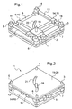
Fig. 1 shows a schematic view of a device for mechanical transmission of translational motion cut free from the conversion mechanism according to the invention, -
Fig. 2 shows a schematic view of a device for mechanical transmission of translational motion with the conversion mechanism according to the invention, -
Fig. 3 shows a non-linear profile according to the invention, and, -
Fig. 4 shows a graph of the movements of an output stage according to an embodiment of the invention. - According to
Fig. 1 and 2 adevice 1 for mechanical transmission of translational motion comprises a first planar andrectangular base plate 2. Each of the corners ofsaid base plate 2 is provided with an integral flange 3 -6 mounted essentially vertically with respect to the plane of therectangular base plate 2. Thedevice 1 is made of stiff material such as metal or stiff composite materials. - A first guide mechanism is configured by two
lateral tubes lateral tubes transverse bars 10, 11 guided along the twolateral tubes - A second guide mechanism is configured by two further
lateral tubes lateral tubes longitudinal bars lateral tubes first guide mechanism - Connection means 17 are provided to link the input means 9 to the output means 14 said connection means 17 being formed with two passages for sliding receipt of said two
transverse bars 10, 11 and - on a different level - two passages for sliding receipt of said twolongitudinal bars pin 18 extends from said connection means 17. - A
conversion mechanism 19 comprises arectangular cover plate 20, saidcover plate 20 having essentially the same rectangular dimensions asbase plate 2. Thecover plate 20 is provided with an at least partly nonlinear profile 21 in an approximately diagonal direction of saidcover plate 20. Said at least partly nonlinear profile 21 is smoothly curved with limited deviations from an overall angle of 45° relative to either of saidfirst guide mechanism second guide mechanism cover plate 20 is mounted onto the flanges 3 - 6 essentially parallel to the plane of therectangular base plate 2. - The
pin 18 is engaged in therectangular cover plate 20 to interact with said at least partly nonlinear profile 21. - The
base plate 2 with the same shape ascover plate 20 may be provided with aprofile 22 mirrored to the at least partly nonlinear profile 21 ofcover plate 20 saidpin 18 being elongated to engage said nonlinear profiles base plate 2 andcover plate 20 for symmetrical loads and in order to free connection means 17 from any moments induced by thepin 18. - The
pin 18 is provided with a ball bearing at the interface to thenon-linear profile 21 in thecover plate 20 and/or at the interface to the at least partially nonlinear profile of thebase plate 2. - The assembly of the mechanical transmission of translational motion starts with mounting the two
lateral tubes lateral tubes base plate 2 together with the input means 9, output means 14 and connection means 17.Cover plate 20 is mounted on the flanges 3 -6 ofbase plate 2 such thatpin 18 is accommodated into said nonlinear profiles cover plate 20 and thebase plate 2. - According to
Fig. 3 a graph shows the relation of the movement of the input means 9 relative to the output means 14 according to the at least partly nonlinear profile 21 incover plate 20, which provides in a first section a for an almost linear transmission from input means 9 to output means 14, during a subsequent section b for slowed down transmission from input means 9 to output means 14 till a reversal between any movements of input means 9 to output means 14, in a following section c again for an almost linear transmission from input means 9 to output means 14, in a further section d for slowed down transmission from input means 9 to output means 14 till a reversal between any movements of input means 9 to output means 14 and along a final section e for a reduced linear transmission from input means 9 to output means 14. - According to
Fig. 4 a further graph shows the relation of the movement of the input means 9 relative to the output means 14 according to the at least partly nonlinear profile 21 incover plate 20 ofFig. 3 when a gear, e. g. a rack - pinion - rack control, is applied to the output means 14 to linearly convert the movements of the output means 14 in an orthogonal direction essentially in line with the direction of the movements of the input means 9 and to stretch said movements of the output means 14 for a subsequent output stage (not shown). - The non
linear profile 21 incover plate 20 of theconversion mechanism 19 is designed according to an analysis of non-linear responses of rotor blades to a pilot's input signal. - Any movement of the input means 9 along the
first guide mechanism pin 18 engaged into the nonlinear profiles cover plate 20 andbase plate 2.Pin 18 moves relative to the nonlinear profile 21 in order to allow the movement of input means 9, with saidpin 18 being deviated by the nonlinear profile 21 in the direction allowed by said twotransverse bars 10, 11 if the nonlinear profile 21 is not inline with the movement of input means 9. Said deviation ofpin 18 is transmitted via the connection means 17 to a translational movement of the output means 14 allowed by said twolongitudinal bars linear profiles conversion mechanism 19.
Claims (8)
- A device (1) for mechanical transmission of translational motions, characterized in that the device (1) is for an actuator / control of rotor blades of an helicopter and comprises:- a planar and rectangular base plate (2) provided with integral flanges (3-6) mounted essentially vertically with respect to the plane of the base on each of the corners of the base plate;- two lateral tubes (7-8) parallel to each other and fitted into the integral flanges (3-6) in a predetermined direction ; two further lateral tubes (12-13) being parallel to each other and fitted into the integral flanges (3-6) in an orthogonal direction relative to the predetermined direction;- input means (9) comprising two transverse bars (10-11) and being guided along the two lateral tubes (7-8) and having a driving input and a first translational guide mechanism with the transverse bars (10, 11) to guide in an input translational motion the input means (9) in a predetermined input translational direction, according to a control signal applied to the driving input;- output means (14) for outputing an output translational motion and having a second translational guide mechanism with longitudinal bars (15, 16) to guide the output means (14) along the two further lateral tubes (12-13) in a output translational direction orthogonal with the input translational direction,- connection means (17) to link the input means (9) to the output means (14)the connection means (17) having input sliding passages for sliding receipt of the transverse bars (10, 11) and output sliding passages for sliding receipt of the longitudinal bars (15, 16), said input sliding passages being vertically on a different level than the output sliding passages, and- a conversion mechanism (19) provided with engagement means (18) extending from said connection means (17), the conversion mechanism (19) further comprises a cover plate (20) having essentially the same rectangular dimensions as the base plate (2) with an at least partly non linear profile (21, 22), the engagement means (18) being engaged in the at least partly non linear profile (21, 22) of the cover plate (20) and to the output means (14) via the connection means (17) to convert the input translational motion into an orthogonal output translational motion with a seamless conversion.
- The device (1) according to claim 1, characterized in that said at least partly non linear profile (21) is integrated to said cover plate (20), said cover plate (20) being essentially parallel to the plane of the longitudinal bars (15, 16).
- The device (1) according to claim 1,
characterized in that said engagement means (18) is a pin extending from said connection means (17) into said at least partly non linear profile (21) of said cover plate (20). - The device (1) according to claim 1,
characterized in that the at least partly non linear profile (21) is smoothly curved with limited deviations from a generally diagonal direction relative to either of said transverse bars (10, 11) or said longitudinal bars (15, 16). - The device (1) according to claim 4,
characterized in that the at least partly non linear profile (21) in plate (20) provides in a first section (a) for an almost linear transmission from input means (9) to output means (14), during a subsequent section (b) for slowed down transmission from input means (9) to output means (14) till a reversal between any movements of input means (9) to output means (14), in a following section (c) again for an almost linear transmission from input means (9) to output means (14), in a further section (d) for slowed down transmission from input means (9) to output means (14) till a reversal between any movements of input means (9) to output means (14) and along a final section (e) for a reduced linear transmission from input means (9) to output means (14). - The device (1) according to claim 1,
characterized in that a gear, e. g. a rack - pinion - rack control is applied to the output means (14) to linearly convert the input translational motion induced by the at least partly non linear profile (21) in a direction essentially in line with the input means (9) and to stretch said movements of the output means (14) for a subsequent output stage. - The device (1) according to claim 1,
characterized in that said device comprises a base plate (2) of the conversion mechanism (19), said base plate (2) being provided with a profile (22) which is congruent to the opposed non-linear profile (21) in the cover plate (20) and in that the engagement means (18) engage the profile (21) in the cover plate (20) and the congruent profile (22) in the base plate (2). - The device (1) according to claim 3,
characterized in that said engagement means (18) is a pin extending from said connection means (17) into said at least partly non linear profile (21) of said cover plate (20), the pin (18) being provided with at least one ball bearing at the interface to the non-linear profile (21) in the cover plate (20).
Priority Applications (1)
| Application Number | Priority Date | Filing Date | Title |
|---|---|---|---|
| EP10400054.2A EP2450276B1 (en) | 2010-11-04 | 2010-11-04 | Mechanical transmission of translational motion |
Applications Claiming Priority (1)
| Application Number | Priority Date | Filing Date | Title |
|---|---|---|---|
| EP10400054.2A EP2450276B1 (en) | 2010-11-04 | 2010-11-04 | Mechanical transmission of translational motion |
Publications (2)
| Publication Number | Publication Date |
|---|---|
| EP2450276A1 EP2450276A1 (en) | 2012-05-09 |
| EP2450276B1 true EP2450276B1 (en) | 2014-01-08 |
Family
ID=43857710
Family Applications (1)
| Application Number | Title | Priority Date | Filing Date |
|---|---|---|---|
| EP10400054.2A Not-in-force EP2450276B1 (en) | 2010-11-04 | 2010-11-04 | Mechanical transmission of translational motion |
Country Status (1)
| Country | Link |
|---|---|
| EP (1) | EP2450276B1 (en) |
Family Cites Families (2)
| Publication number | Priority date | Publication date | Assignee | Title |
|---|---|---|---|---|
| JP2007309783A (en) * | 2006-05-18 | 2007-11-29 | Yokogawa Electric Corp | XY stage |
| DE102008044824A1 (en) * | 2007-09-04 | 2009-03-05 | Luk Lamellen Und Kupplungsbau Beteiligungs Kg | Pedal arrangement for actuating a clutch |
-
2010
- 2010-11-04 EP EP10400054.2A patent/EP2450276B1/en not_active Not-in-force
Also Published As
| Publication number | Publication date |
|---|---|
| EP2450276A1 (en) | 2012-05-09 |
Similar Documents
| Publication | Publication Date | Title |
|---|---|---|
| EP2234877B1 (en) | Aircraft control surface | |
| RU2561159C1 (en) | Electromechanical actuator for aircraft control airfoil and aircraft equipped with such actuator | |
| EP2213426A1 (en) | Electric Scissors | |
| WO2008054470A3 (en) | Multi-mode unmanned and manned vehicle systems and methods | |
| EP2415669B1 (en) | Control system | |
| RU2009126561A (en) | SYSTEM FOR IMPLEMENTATION OF AUTOMATIC KITE FLIGHT CONTROL | |
| US9422061B2 (en) | Device for controlling the power of an engine and for controlling a thrust reverser device | |
| US10106245B2 (en) | Automatic flight control actuator systems | |
| US8548651B2 (en) | Device for piloting a vehicle and method for the motorised assistance and control of such a piloting device | |
| US7890222B1 (en) | Mechanical flight control auxiliary power assist system | |
| EP2301845A3 (en) | Thrust reverser actuation | |
| CN110498061A (en) | Method of changing manned machine to unmanned aerial vehicle based on rudder control system modification | |
| EP2450276A1 (en) | Mechanical transmission of translational motion | |
| US2744420A (en) | Cable slack compensator | |
| CN110160411B (en) | Movable steering engine load simulator supporting device | |
| US9482312B2 (en) | Rope drive anchoring assembly | |
| US7668627B2 (en) | Mechanical flight control auxiliary power assist system | |
| US9369068B2 (en) | Control device for drive device | |
| US9709158B2 (en) | Anti-backlash gear control device | |
| EP0068654B1 (en) | Self-tensioning motor transmission control system | |
| CN114368473B (en) | A push-pull control cable for aircraft | |
| EP2242945B1 (en) | Valve actuator | |
| EP2607228B1 (en) | Steering system for boats | |
| JP2001074121A (en) | Power transmission device | |
| CN222247628U (en) | Aircraft rocker arm support assembly |
Legal Events
| Date | Code | Title | Description |
|---|---|---|---|
| PUAI | Public reference made under article 153(3) epc to a published international application that has entered the european phase |
Free format text: ORIGINAL CODE: 0009012 |
|
| AK | Designated contracting states |
Kind code of ref document: A1 Designated state(s): AL AT BE BG CH CY CZ DE DK EE ES FI FR GB GR HR HU IE IS IT LI LT LU LV MC MK MT NL NO PL PT RO RS SE SI SK SM TR |
|
| AX | Request for extension of the european patent |
Extension state: BA ME |
|
| 17P | Request for examination filed |
Effective date: 20120423 |
|
| 17Q | First examination report despatched |
Effective date: 20130204 |
|
| GRAP | Despatch of communication of intention to grant a patent |
Free format text: ORIGINAL CODE: EPIDOSNIGR1 |
|
| INTG | Intention to grant announced |
Effective date: 20130904 |
|
| GRAS | Grant fee paid |
Free format text: ORIGINAL CODE: EPIDOSNIGR3 |
|
| GRAA | (expected) grant |
Free format text: ORIGINAL CODE: 0009210 |
|
| AK | Designated contracting states |
Kind code of ref document: B1 Designated state(s): AL AT BE BG CH CY CZ DE DK EE ES FI FR GB GR HR HU IE IS IT LI LT LU LV MC MK MT NL NO PL PT RO RS SE SI SK SM TR |
|
| REG | Reference to a national code |
Ref country code: GB Ref legal event code: FG4D |
|
| REG | Reference to a national code |
Ref country code: CH Ref legal event code: EP |
|
| REG | Reference to a national code |
Ref country code: IE Ref legal event code: FG4D |
|
| REG | Reference to a national code |
Ref country code: AT Ref legal event code: REF Ref document number: 648560 Country of ref document: AT Kind code of ref document: T Effective date: 20140215 |
|
| REG | Reference to a national code |
Ref country code: DE Ref legal event code: R096 Ref document number: 602010012950 Country of ref document: DE Effective date: 20140220 |
|
| RAP2 | Party data changed (patent owner data changed or rights of a patent transferred) |
Owner name: AIRBUS HELICOPTERS DEUTSCHLAND GMBH |
|
| REG | Reference to a national code |
Ref country code: AT Ref legal event code: MK05 Ref document number: 648560 Country of ref document: AT Kind code of ref document: T Effective date: 20140108 |
|
| REG | Reference to a national code |
Ref country code: NL Ref legal event code: VDEP Effective date: 20140108 |
|
| REG | Reference to a national code |
Ref country code: LT Ref legal event code: MG4D |
|
| PG25 | Lapsed in a contracting state [announced via postgrant information from national office to epo] |
Ref country code: LT Free format text: LAPSE BECAUSE OF FAILURE TO SUBMIT A TRANSLATION OF THE DESCRIPTION OR TO PAY THE FEE WITHIN THE PRESCRIBED TIME-LIMIT Effective date: 20140108 Ref country code: IS Free format text: LAPSE BECAUSE OF FAILURE TO SUBMIT A TRANSLATION OF THE DESCRIPTION OR TO PAY THE FEE WITHIN THE PRESCRIBED TIME-LIMIT Effective date: 20140508 Ref country code: NO Free format text: LAPSE BECAUSE OF FAILURE TO SUBMIT A TRANSLATION OF THE DESCRIPTION OR TO PAY THE FEE WITHIN THE PRESCRIBED TIME-LIMIT Effective date: 20140408 |
|
| PG25 | Lapsed in a contracting state [announced via postgrant information from national office to epo] |
Ref country code: AT Free format text: LAPSE BECAUSE OF FAILURE TO SUBMIT A TRANSLATION OF THE DESCRIPTION OR TO PAY THE FEE WITHIN THE PRESCRIBED TIME-LIMIT Effective date: 20140108 Ref country code: SE Free format text: LAPSE BECAUSE OF FAILURE TO SUBMIT A TRANSLATION OF THE DESCRIPTION OR TO PAY THE FEE WITHIN THE PRESCRIBED TIME-LIMIT Effective date: 20140108 Ref country code: NL Free format text: LAPSE BECAUSE OF FAILURE TO SUBMIT A TRANSLATION OF THE DESCRIPTION OR TO PAY THE FEE WITHIN THE PRESCRIBED TIME-LIMIT Effective date: 20140108 Ref country code: PT Free format text: LAPSE BECAUSE OF FAILURE TO SUBMIT A TRANSLATION OF THE DESCRIPTION OR TO PAY THE FEE WITHIN THE PRESCRIBED TIME-LIMIT Effective date: 20140508 Ref country code: CY Free format text: LAPSE BECAUSE OF FAILURE TO SUBMIT A TRANSLATION OF THE DESCRIPTION OR TO PAY THE FEE WITHIN THE PRESCRIBED TIME-LIMIT Effective date: 20140108 Ref country code: FI Free format text: LAPSE BECAUSE OF FAILURE TO SUBMIT A TRANSLATION OF THE DESCRIPTION OR TO PAY THE FEE WITHIN THE PRESCRIBED TIME-LIMIT Effective date: 20140108 Ref country code: ES Free format text: LAPSE BECAUSE OF FAILURE TO SUBMIT A TRANSLATION OF THE DESCRIPTION OR TO PAY THE FEE WITHIN THE PRESCRIBED TIME-LIMIT Effective date: 20140108 |
|
| PG25 | Lapsed in a contracting state [announced via postgrant information from national office to epo] |
Ref country code: LV Free format text: LAPSE BECAUSE OF FAILURE TO SUBMIT A TRANSLATION OF THE DESCRIPTION OR TO PAY THE FEE WITHIN THE PRESCRIBED TIME-LIMIT Effective date: 20140108 Ref country code: HR Free format text: LAPSE BECAUSE OF FAILURE TO SUBMIT A TRANSLATION OF THE DESCRIPTION OR TO PAY THE FEE WITHIN THE PRESCRIBED TIME-LIMIT Effective date: 20140108 Ref country code: BE Free format text: LAPSE BECAUSE OF FAILURE TO SUBMIT A TRANSLATION OF THE DESCRIPTION OR TO PAY THE FEE WITHIN THE PRESCRIBED TIME-LIMIT Effective date: 20140108 Ref country code: RS Free format text: LAPSE BECAUSE OF FAILURE TO SUBMIT A TRANSLATION OF THE DESCRIPTION OR TO PAY THE FEE WITHIN THE PRESCRIBED TIME-LIMIT Effective date: 20140108 |
|
| REG | Reference to a national code |
Ref country code: DE Ref legal event code: R097 Ref document number: 602010012950 Country of ref document: DE |
|
| PG25 | Lapsed in a contracting state [announced via postgrant information from national office to epo] |
Ref country code: DK Free format text: LAPSE BECAUSE OF FAILURE TO SUBMIT A TRANSLATION OF THE DESCRIPTION OR TO PAY THE FEE WITHIN THE PRESCRIBED TIME-LIMIT Effective date: 20140108 Ref country code: EE Free format text: LAPSE BECAUSE OF FAILURE TO SUBMIT A TRANSLATION OF THE DESCRIPTION OR TO PAY THE FEE WITHIN THE PRESCRIBED TIME-LIMIT Effective date: 20140108 Ref country code: CZ Free format text: LAPSE BECAUSE OF FAILURE TO SUBMIT A TRANSLATION OF THE DESCRIPTION OR TO PAY THE FEE WITHIN THE PRESCRIBED TIME-LIMIT Effective date: 20140108 Ref country code: RO Free format text: LAPSE BECAUSE OF FAILURE TO SUBMIT A TRANSLATION OF THE DESCRIPTION OR TO PAY THE FEE WITHIN THE PRESCRIBED TIME-LIMIT Effective date: 20140108 |
|
| PLBE | No opposition filed within time limit |
Free format text: ORIGINAL CODE: 0009261 |
|
| STAA | Information on the status of an ep patent application or granted ep patent |
Free format text: STATUS: NO OPPOSITION FILED WITHIN TIME LIMIT |
|
| PG25 | Lapsed in a contracting state [announced via postgrant information from national office to epo] |
Ref country code: PL Free format text: LAPSE BECAUSE OF FAILURE TO SUBMIT A TRANSLATION OF THE DESCRIPTION OR TO PAY THE FEE WITHIN THE PRESCRIBED TIME-LIMIT Effective date: 20140108 Ref country code: SK Free format text: LAPSE BECAUSE OF FAILURE TO SUBMIT A TRANSLATION OF THE DESCRIPTION OR TO PAY THE FEE WITHIN THE PRESCRIBED TIME-LIMIT Effective date: 20140108 |
|
| 26N | No opposition filed |
Effective date: 20141009 |
|
| REG | Reference to a national code |
Ref country code: DE Ref legal event code: R082 Ref document number: 602010012950 Country of ref document: DE Representative=s name: GPI & ASSOCIES, FR |
|
| REG | Reference to a national code |
Ref country code: DE Ref legal event code: R097 Ref document number: 602010012950 Country of ref document: DE Effective date: 20141009 |
|
| REG | Reference to a national code |
Ref country code: DE Ref legal event code: R082 Ref document number: 602010012950 Country of ref document: DE Representative=s name: GPI & ASSOCIES, FR Effective date: 20150112 Ref country code: DE Ref legal event code: R081 Ref document number: 602010012950 Country of ref document: DE Owner name: AIRBUS HELICOPTERS DEUTSCHLAND GMBH, DE Free format text: FORMER OWNER: EUROCOPTER DEUTSCHLAND GMBH, 86609 DONAUWOERTH, DE Effective date: 20150112 |
|
| PG25 | Lapsed in a contracting state [announced via postgrant information from national office to epo] |
Ref country code: SI Free format text: LAPSE BECAUSE OF FAILURE TO SUBMIT A TRANSLATION OF THE DESCRIPTION OR TO PAY THE FEE WITHIN THE PRESCRIBED TIME-LIMIT Effective date: 20140108 |
|
| PG25 | Lapsed in a contracting state [announced via postgrant information from national office to epo] |
Ref country code: LU Free format text: LAPSE BECAUSE OF FAILURE TO SUBMIT A TRANSLATION OF THE DESCRIPTION OR TO PAY THE FEE WITHIN THE PRESCRIBED TIME-LIMIT Effective date: 20141104 Ref country code: MC Free format text: LAPSE BECAUSE OF FAILURE TO SUBMIT A TRANSLATION OF THE DESCRIPTION OR TO PAY THE FEE WITHIN THE PRESCRIBED TIME-LIMIT Effective date: 20140108 |
|
| REG | Reference to a national code |
Ref country code: CH Ref legal event code: PL |
|
| GBPC | Gb: european patent ceased through non-payment of renewal fee |
Effective date: 20141104 |
|
| PG25 | Lapsed in a contracting state [announced via postgrant information from national office to epo] |
Ref country code: LI Free format text: LAPSE BECAUSE OF NON-PAYMENT OF DUE FEES Effective date: 20141130 Ref country code: CH Free format text: LAPSE BECAUSE OF NON-PAYMENT OF DUE FEES Effective date: 20141130 |
|
| REG | Reference to a national code |
Ref country code: IE Ref legal event code: MM4A |
|
| PG25 | Lapsed in a contracting state [announced via postgrant information from national office to epo] |
Ref country code: IE Free format text: LAPSE BECAUSE OF NON-PAYMENT OF DUE FEES Effective date: 20141104 Ref country code: GB Free format text: LAPSE BECAUSE OF NON-PAYMENT OF DUE FEES Effective date: 20141104 |
|
| REG | Reference to a national code |
Ref country code: FR Ref legal event code: PLFP Year of fee payment: 6 |
|
| PG25 | Lapsed in a contracting state [announced via postgrant information from national office to epo] |
Ref country code: SM Free format text: LAPSE BECAUSE OF FAILURE TO SUBMIT A TRANSLATION OF THE DESCRIPTION OR TO PAY THE FEE WITHIN THE PRESCRIBED TIME-LIMIT Effective date: 20140108 |
|
| PG25 | Lapsed in a contracting state [announced via postgrant information from national office to epo] |
Ref country code: GR Free format text: LAPSE BECAUSE OF FAILURE TO SUBMIT A TRANSLATION OF THE DESCRIPTION OR TO PAY THE FEE WITHIN THE PRESCRIBED TIME-LIMIT Effective date: 20140409 Ref country code: BG Free format text: LAPSE BECAUSE OF FAILURE TO SUBMIT A TRANSLATION OF THE DESCRIPTION OR TO PAY THE FEE WITHIN THE PRESCRIBED TIME-LIMIT Effective date: 20140108 |
|
| PG25 | Lapsed in a contracting state [announced via postgrant information from national office to epo] |
Ref country code: HU Free format text: LAPSE BECAUSE OF FAILURE TO SUBMIT A TRANSLATION OF THE DESCRIPTION OR TO PAY THE FEE WITHIN THE PRESCRIBED TIME-LIMIT; INVALID AB INITIO Effective date: 20101104 Ref country code: MT Free format text: LAPSE BECAUSE OF FAILURE TO SUBMIT A TRANSLATION OF THE DESCRIPTION OR TO PAY THE FEE WITHIN THE PRESCRIBED TIME-LIMIT Effective date: 20140108 Ref country code: TR Free format text: LAPSE BECAUSE OF FAILURE TO SUBMIT A TRANSLATION OF THE DESCRIPTION OR TO PAY THE FEE WITHIN THE PRESCRIBED TIME-LIMIT Effective date: 20140108 |
|
| REG | Reference to a national code |
Ref country code: FR Ref legal event code: PLFP Year of fee payment: 7 |
|
| REG | Reference to a national code |
Ref country code: FR Ref legal event code: PLFP Year of fee payment: 8 |
|
| PG25 | Lapsed in a contracting state [announced via postgrant information from national office to epo] |
Ref country code: MK Free format text: LAPSE BECAUSE OF FAILURE TO SUBMIT A TRANSLATION OF THE DESCRIPTION OR TO PAY THE FEE WITHIN THE PRESCRIBED TIME-LIMIT Effective date: 20140108 |
|
| PG25 | Lapsed in a contracting state [announced via postgrant information from national office to epo] |
Ref country code: AL Free format text: LAPSE BECAUSE OF FAILURE TO SUBMIT A TRANSLATION OF THE DESCRIPTION OR TO PAY THE FEE WITHIN THE PRESCRIBED TIME-LIMIT Effective date: 20140108 |
|
| PGFP | Annual fee paid to national office [announced via postgrant information from national office to epo] |
Ref country code: DE Payment date: 20211118 Year of fee payment: 12 |
|
| PGFP | Annual fee paid to national office [announced via postgrant information from national office to epo] |
Ref country code: IT Payment date: 20221124 Year of fee payment: 13 Ref country code: FR Payment date: 20221129 Year of fee payment: 13 |
|
| REG | Reference to a national code |
Ref country code: DE Ref legal event code: R119 Ref document number: 602010012950 Country of ref document: DE |
|
| P01 | Opt-out of the competence of the unified patent court (upc) registered |
Effective date: 20230530 |
|
| PG25 | Lapsed in a contracting state [announced via postgrant information from national office to epo] |
Ref country code: DE Free format text: LAPSE BECAUSE OF NON-PAYMENT OF DUE FEES Effective date: 20230601 |
|
| PG25 | Lapsed in a contracting state [announced via postgrant information from national office to epo] |
Ref country code: FR Free format text: LAPSE BECAUSE OF NON-PAYMENT OF DUE FEES Effective date: 20231130 |
|
| PG25 | Lapsed in a contracting state [announced via postgrant information from national office to epo] |
Ref country code: FR Free format text: LAPSE BECAUSE OF NON-PAYMENT OF DUE FEES Effective date: 20231130 |
|
| PG25 | Lapsed in a contracting state [announced via postgrant information from national office to epo] |
Ref country code: IT Free format text: LAPSE BECAUSE OF NON-PAYMENT OF DUE FEES Effective date: 20231104 |
|
| PG25 | Lapsed in a contracting state [announced via postgrant information from national office to epo] |
Ref country code: IT Free format text: LAPSE BECAUSE OF NON-PAYMENT OF DUE FEES Effective date: 20231104 |