EP2450271A2 - Mooring system for a vessel - Google Patents
Mooring system for a vessel Download PDFInfo
- Publication number
- EP2450271A2 EP2450271A2 EP10194842A EP10194842A EP2450271A2 EP 2450271 A2 EP2450271 A2 EP 2450271A2 EP 10194842 A EP10194842 A EP 10194842A EP 10194842 A EP10194842 A EP 10194842A EP 2450271 A2 EP2450271 A2 EP 2450271A2
- Authority
- EP
- European Patent Office
- Prior art keywords
- arm
- mooring system
- mooring
- robot arm
- attachment unit
- Prior art date
- Legal status (The legal status is an assumption and is not a legal conclusion. Google has not performed a legal analysis and makes no representation as to the accuracy of the status listed.)
- Granted
Links
Images



Classifications
-
- B—PERFORMING OPERATIONS; TRANSPORTING
- B63—SHIPS OR OTHER WATERBORNE VESSELS; RELATED EQUIPMENT
- B63B—SHIPS OR OTHER WATERBORNE VESSELS; EQUIPMENT FOR SHIPPING
- B63B21/00—Tying-up; Shifting, towing, or pushing equipment; Anchoring
-
- B—PERFORMING OPERATIONS; TRANSPORTING
- B63—SHIPS OR OTHER WATERBORNE VESSELS; RELATED EQUIPMENT
- B63B—SHIPS OR OTHER WATERBORNE VESSELS; EQUIPMENT FOR SHIPPING
- B63B21/00—Tying-up; Shifting, towing, or pushing equipment; Anchoring
- B63B2021/001—Mooring bars, yokes, or the like, e.g. comprising articulations on both ends
Definitions
- the present invention relates to a mooring system for a vessel.
- Figs. 1A and 1B are schematic diagrams illustrating the mobile harbor in accordance with the related research.
- the mobile harbor 100 which is a floating body may perform a loading and unloading operation by using a crane 20.
- Fig. 1A illustrates a loading and unloading operation between the mobile harbor 10 and a large container carrier 30, and
- Fig. 1B illustrates a loading and unloading operation between the mobile harbor 10 and a quay wall 40.
- a vessel in general, includes a windlass for winding an anchor cable or a mooring winch for winding a mooring rope, in order to moor the vessel in a harbor, and the harbor includes a mooring facility for fixing the mooring rope of the vessel.
- the conventional vessel or harbor is operated by a manual system depending on human power. Such a manual system has a problem in safety accidents and operation efficiency.
- the present invention provides a mooring system for a vessel capable of minimizing the time and effort required for a mooring operation on vessels, and maintaining a stable mooring state such that cargos can be smoothly loaded and unloaded.
- a mooring system for a vessel including: an attachment unit configured to be detachably attached to a hull of the vessel; a robot arm including a plurality of arms, the arms being coupled to each other to turn in a vertical direction, the robot arm extending by an arm actuator provided thereto to transfer the attachment unit to an attachment position of the hull; a rotation unit connected to the robot arm and allowing the robot arm to turn in a horizontal direction; and a mooring winch for winding a mooring cable to draw the attachment unit.
- a floating body including the mooring system.
- a quay wall including the mooring system
- FIGs. 2A and 2B are schematic views of a mooring system for a vessel in accordance with an embodiment of the present invention.
- Fig. 2A is a side view of the mooring system while the mooring system is mooring a vessel
- Fig. 2B is a perspective view of the mooring system while a floating body (or a floating structure) including the mooring system sails.
- the mooring system 200 includes an attachment unit 210, a robot arm 220, a rotation unit 230, a mooring winch 240, and a robot arm winch 250.
- the robot arm 220 includes a plurality of arms which are coupled with hinges to turn in a vertical direction.
- the robot arm 220 may be extended through extension of an arm actuator to transfer the attachment unit 210 to an attachment position of a hull.
- the robot arm 220 may include a first arm 223 having an end coupled to the rotation unit 230 provided on an installation surface and a second arm 224 having an end coupled to the other end of the first arm 223 with a hinge 225.
- the first arm 223 is coupled to the rotation unit 230 with a hinge 226 to turn in the vertical direction.
- the arm actuator may have a hydraulic cylinder 300.
- the cylinder 300 is connected between the first and second arms 223 and 224 and extends to transfer the attachment unit 210.
- the hydraulic cylinder 300 and the second arm 224 are connected through a spring 224c to absorb an impact applied to the second arm 224.
- the robot arm 220 has a protrusion portion 224d which protrudes to be positioned behind the connection member 212 of the attachment unit 210, and the connection member 212 is connected to the protrusion portion 224d through a spring 212c to absorb an impact applied to the attachment unit 210.
- the robot arm 220 of the mooring system is not limited to the 2-arm link structure illustrated in Figs. 2A and 2B , but may be constructed to have a variety of link structures.
- the robot arm 220 may include one or more additional arms, or may have a 4-arm link structure in which a pair of 2-arm links is formed between the rotation unit 230 to the attachment unit 210.
- Fig. 3A is a conceptual diagram illustrating a multi-stage hydraulic cylinder and hydraulic circuits in accordance with the embodiment of the present invention
- Fig. 3B is a cross-sectional view of the multi-stage hydraulic cylinder.
- the hydraulic cylinder 300 in accordance with the embodiment of the present invention may include a multi-stage hydraulic cylinder which independently controls the stroke of two or more piston to perform extension and contraction for positioning of the attachment unit 210 and absorption of an impact applied to the attachment unit 210.
- One piston rod may freely move to provide room for the vessel which rolls or pitches on the sea, and absorb an impact applied by a vessel, in a state that the hydraulic cylinder 300 is in neutral.
- another piston rod may stop in a state that the multi-stage hydraulic cylinder 300 is in neutral.
- the multi-stage hydraulic cylinder 300 includes a cylinder housing 310 having a space formed therein and an opened upper surface and the first and the second-stage piston rod 320 and 330.
- the first-stage piston rod 320 is inserted into an upper surface (right side in Fig. 3A ) of the cylinder housing 310, divides an internal space of the cylinder housing 310 to form a first and a second chamber 321 and 322 to thereby have, and has a space formed therein and an opened upper surface.
- the second-stage piston rod 330 is inserted into the upper surface of the first-stage piston rod 320 and divides an internal space of the first-stage piston rod 320 to form a third and a fourth chamber 331 and 332.
- the first to fourth chambers 321, 322, 331, and 332 may include first to fourth openings 321a, 322a, 331a, and 332a, respectively, which are sealed and with which a fluid communicates to apply an oil pressure.
- the first-stage and second-stage piston rods 320 and 330 have respective hollow holes 323 and 333 formed therein, and a fluid may communicate with the third and fourth chambers 331 and 332 through flow paths formed in the respective hollow holes.
- the cylinder housing 310 has an opened lower surface (left side in Fig. 3A ), and a fluid may communicate with the third and fourth openings 331a and 332a through the lower surface of the cylinder housing 310.
- An oil pressure applied to the pair of the first and second chambers 321 and 322 and an oil pressure applied to the pair of the third and fourth chambers 331 and 332 may be controlled by a first-stage hydraulic circuit 340 and a second-stage hydraulic circuit 350, respectively, which are independently provided.
- a first-stage hydraulic circuit 340 and a second-stage hydraulic circuit 350 are independently provided.
- the first-stage piston rod 320 is moved vertically (in the horizontal direction in Fig. 3A ), and the length of the hydraulic cylinder 300 is extended or contracted.
- the second-stage piston rod 330 is moved vertically, and the length of the hydraulic cylinder 300 is extended or contracted.
- the first-stage hydraulic circuit 340 and the second-stage hydraulic circuit 350 may include check valves 341, 342, 351, and 352 through which a fluid communicates with the first to fourth openings 321a, 322a, 331a, and 332a, respectively, to apply an oil pressure.
- Chambers in any one pair of the pair of the first and second chambers 321 and 322 and the pair of the third and fourth chambers 331 and 332 may communicate with each other when the hydraulic cylinder 300 is in neutral state.
- the other pair of chambers may be disconnected from an external hydraulic circuit when the hydraulic cylinder 300 is in neutral state.
- the pair of the first and second chambers 321 and 322 may communicate with each other such that the first-stage piston rod 320 freely moves in case of neutral state.
- the pair of the third and fourth chambers 331 and 332 may be disconnected from an external hydraulic circuit to stop the second-stage piston rod 330 in case of neutral state.
- the first-stage hydraulic circuit 340 can make the first-stage piston rod 320 freely move.
- the first-stage hydraulic circuit 340 may include an ABT-connected four-direction control valve 344.
- the second-stage hydraulic circuit 350 can stop the second-stage piston rod 330.
- the second-stage hydraulic circuit 350 may include a closed-center four-direction control valve 354.
- the two-stage cylinder has been described, but may be extended to three stages or more.
- two or more piston rods may be independently controlled to perform the extension of the cylinder length and the impact absorption at the same time. Therefore, the multi-stage cylinder 300 may have two or more functions through a simple construction.
- Fig. 4 is a schematic view of the attachment unit 210 in accordance with the embodiment of the present invention.
- the attachment unit 210 is detachably attached to a hull of a vessel to be berthed, such as a container carrier.
- the attachment unit 210 may include a plurality of suction pads 211 for generating an attachment force by which the attachment unit 210 is attached to the hull.
- Each of the suction pads 211 may be attached to the hull by vacuum supplied through a vacuum supply line from a vacuum supply unit (not illustrated).
- the suction pad 211 may include a plurality of vacuum holes to which vacuum is supplied.
- the suction pad 211 may include an electromagnet which is attached to the hull by a magnetic force caused by power supply.
- the attachment unit 210 may include a connection member 212 for connecting the suction pad 211 to an end of the robot arm 220.
- the robot arm 220 and the connection member 212 may be coupled by a ball joint 212a so as to rotate about each other.
- the suction pads 211 may be coupled to auxiliary connection members 213 by hinges 213b, respectively.
- the suction pads 211 may be arranged in line or in a two-dimensional manner with respect to the connection member 212.
- Each of the auxiliary connection members 213 has an end coupled to the connection member 212 by the ball joint 213a.
- the suction pads 211 may be moved with a multi degree of freedom by the ball joints 212a and 213a and the hinges 213b. Therefore, the suction pads 211 may change the posture in correspondence to various shapes of hulls.
- the ball joints and hinges 212a, 213a and 213b may be substituted with joints of different type.
- Fig. 5 is a schematic view of the rotation unit 230 in accordance with the embodiment of the present invention.
- the rotation unit 230 is connected to the robot arm 220 to rotate the robot arm 220 in a horizontal direction (e. g., in a left and right direction) within a predetermined angle range based on the axis perpendicular to the installation surface.
- a rotational force is applied.
- the rotation unit 230 includes a rotation member 234, a rotation adjustment part 232, a fixed shaft 231, and a restoration part 233.
- the rotation member 234 is connected to the robot arm 220 to rotate in the horizontal direction together with the robot arm 220.
- the rotation adjustment part 232 allows the rotation member 234 to rotate from an initial position, when a predetermined load or a load more than that is applied.
- the fixed shaft 231 includes a stopper for limiting the rotation member 234 within a predetermined angle range, for example, 15 degrees and is fixed to the installation surface.
- the restoration part 233 restores the rotated rotation member 234 to the initial position.
- the rotation adjustment part 232 includes a case 232a coupled to be fixed to the rotation member 234, and the case 232a is rotated together with the rotation member 234.
- the rotation of the case 232a is limited by the stopper 231a.
- a ball 232c is provided inside the case 232a, and has a portion inserted into a hole 231c formed in the fixed shaft 231. When a rotational force of a predetermined load or more is applied, the ball 232c may be moved out of the hall 231c.
- a spring 232b applies a compressive force to the ball 232c such that the compressive force is directed toward the hole 231c. When a load less than the predetermined load is applied, the spring 232b stops the ball 232c.
- the restoration part 233 includes a spring 233d having both ends coupled to the rotation adjustment part 232 and the fixed shaft 231, respectively.
- the spring 233d is lengthened to restore the rotation member 234.
- the mooring winch 240 winds the mooring cable 245 to draw the hull attached to the attachment unit 210 toward the installation surface.
- the mooring winch 240 serves to suppress the vessel from moving away from the mooring system 200 when the attachment unit 210 is attached to the hull.
- the mooring winch 240 includes a variety of sensors and actuators which control a mooring force to be automatically and constantly maintained.
- the mooring operation may be stably and automatically performed in correspondence to a drift, winds, waves, tides, and the like.
- the driving power of the robot arm 220 may be turned off.
- the mooring winch 240 may cover all or most of the load generated by the mooring of the vessel such that the load is not applied to the robot arm 220.
- the mooring winch 240 may free the robot arm 220 from the load.
- the hydraulic cylinder 300 may be freely extended and contracted when the mooring winch serves to suppress the vessel. Therefore the physical fatigue of the robot arm 220 may be prevented, and the structure may be simplified.
- the mooring cable 245 has an end connected to the attachment unit 210 to draw the attachment unit 210.
- the mooring cable 245 may be directly connected to the connection member 212 or connected through a separate member.
- the mooring cable 245 may be connected to an end of the robot arm 220.
- the robot arm winch 250 may wind the robot arm cable 255 to draw the robot arm 220. Similar to the mooring winch 240, the robot arm winch 250 may cover a load generated when the attachment unit 210 is attached to the hull, thereby preventing the physical fatigue of the structure.
- the mooring system 200 in accordance with the embodiment of the present invention may include a variety of actuators for driving the winch, the hinges, the ball joints, and the cylinder.
- a position and posture of the attachment unit 210 may be adjusted in correspondence to a size or a shape of a vessel to be berthed, thereby making it possible to berth the vessel efficiently. Furthermore, the docking impact is absorbed by the multi-stage cylinder 300 and the elasticity of the springs 224c and 212c, and the distance between vessels is constantly maintained to stably berth or anchor the vessels. Furthermore, the mooring system 200 may minimize the use of human power such that the mooring operation is automatically performed, thereby reducing the danger of safety accident and increasing the efficiency.
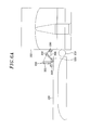
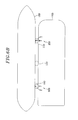
- Figs. 6A and 6B are conceptual diagrams illustrating a state in which a mobile harbor having the mooring system mounted thereon is berthing at a container carrier.
- Fig. 6A is a front view
- Fig. 6B is a plan view.
- a plurality of the mooring systems 200 may be disposed on a side surface of a floating body such as a mobile harbor.
- the mobile harbor 100 may include a vessel which may move by using its own power or a floating body moored on the sea.
- the mobile harbor 100 may transfer containers between the container carrier 150 and a harbor on the land, and temporarily load containers in place of the harbor on the land, while floating on the sea.
- the mobile harbor 100 may include a platform having a space in which a container is loaded, a loading device (e. g., a crane) for handling a container, a location determining device for acquiring information regarding the location of the platform, and a balancing device for adjusting the platform such that the platform can be maintained in a vertical location correspondingly to a change in the weight based on the loading and unloading of the container.
- a loading device e. g., a crane
- location determining device for acquiring information regarding the location of the platform
- a balancing device for adjusting the platform such that the platform can be maintained in a vertical location correspondingly to a change in the weight based on the loading and unloading of the container.
- the mobile harbor 100 in accordance with the embodiment of the present invention may further include a fender 110 installed between the mobile harbor 100 and the hull of a vessel such as the container carrier 150. Therefore, when the mooring cable 245 is wound, the fender 110 prevents the hull from colliding with the mobile harbor 100, and simultaneously pushes the hull to maintain the tension of the mooring cable 245. Therefore, even when the sea condition is not stable, for example, even when the waves are high, the mooring operation for the vessel can be performed stably.
- the fender 110 may be installed on the mobile harbor 100, the hull of the container carrier 150, or another structure.
- the fender 110 may have a variety of installation structures.
- the fender 110 may be installed to float on the surface of the sea or fixed to be positioned at a predetermined level.
- the fender 110 may be formed of a structure capable of enduring a strong external force and frictional force, while absorbing an impact.
- Fig. 7 is a conceptual diagram illustrating a state in which a mobile harbor is berthing at a quay wall in which the mooring system in accordance with the embodiment of the present invention is disposed.
- the mooring system 200 may be disposed at a quay wall 140 or a quay on the land and used when a vessel is berthed or moored at the quay wall on the land.
- the mooring system 200 may moor the mobile harbor 100 at a proper position while moving along a rail 145 formed on the quay wall 140.
- another vessel such as a container carrier or a floating body may be moored at the quay wall 140 where the mooring system in accordance with the embodiment of the present invention is installed.
- a mooring method in a case in which the mooring system in accordance with the embodiment of the present invention is installed in a mobile harbor will be described.
- the mooring method may include a step of transferring the attachment unit 210 to the hull by using the robot arm 220, a step of attaching the attachment unit 210 to the hull, a step of putting the hydraulic cylinder 300 of the robot arm 220 into neutral, and a step of winding the mooring cable 245.
- the mobile harbor 100 is approximated to the container carrier 150 to be berthed, and an optimal attachment position is selected.
- the attachment unit 210 may be transferred to the position, by the movement of the robot arm 220 and the posture change of the attachment unit 210.
- the movement of the robot arm 220 may be performed by the extension of the hydraulic cylinder 300 and the suction pads 211 are rotated by the ball joints 212a and 213a and hinges 213b.
- the attachment unit 210 may be attached to the hull by the supply of vacuum or a magnetic force.
- the mooring cable 245 is wound by the mooring winch 240 to draw the attachment unit 210, in order to cover a load caused by docking or mooring the vessel.
- the hydraulic cylinder 300 of the robot arm 220 is put into neutral.
- the power (or actuators) of the hinges 213b or the ball joints 212a and 213a may be turned off, in order to free the robot arm 220 from the load.
- the fender 110 may be installed between the mobile harbor 100 having the robot arm 220 installed thereon and the hull of the container carrier 150.
- the mooring system may minimize the time and effort required for a mooring operation, and may maintain a stable mooring state therebetween such that cargo is smoothly loaded and unloaded.
- the mobile harbor in accordance with the embodiment of the present invention performs a loading and unloading operation for a large container carrier on the sea. Therefore, the cargo transportation of a large container carrier, which needs to be performed in deep water, may be efficiently processed, whereby it will contribute to strengthening the harbor system competitiveness.
Landscapes
- Chemical & Material Sciences (AREA)
- Engineering & Computer Science (AREA)
- Combustion & Propulsion (AREA)
- Mechanical Engineering (AREA)
- Ocean & Marine Engineering (AREA)
- Jib Cranes (AREA)
- Load-Engaging Elements For Cranes (AREA)
Abstract
Description
- The present invention relates to a mooring system for a vessel.
- Recently, in order to improve the efficiency of marine transportation using containers, large vessels have been used in order to improve the cost effectiveness by increasing the cargo amount. In this connection, there is a demand for the development of a new system which is capable of loading and unloading cargo on the sea remote from the land, without berthing such large vessels at a quay wall of a harbor which is provided on the land. Thus, research into a mobile harbor allowing a large ship to anchor in the sea away from the land and to handle cargos, rather than making a large ship to come alongside the pier in the harbor, has been under way.
-
Figs. 1A and 1B are schematic diagrams illustrating the mobile harbor in accordance with the related research. Themobile harbor 100 which is a floating body may perform a loading and unloading operation by using acrane 20.Fig. 1A illustrates a loading and unloading operation between themobile harbor 10 and alarge container carrier 30, andFig. 1B illustrates a loading and unloading operation between themobile harbor 10 and a quaywall 40. - When a mobile harbor is used to load and unload cargos while a large container carrier is anchored in the sea remote from the land, containers loaded and/or to be loaded on the large container carrier need to be distributed to several small mobile harbors and transported between the large container carrier and a harbor provided on the land. In this case, the number of berthing operations of the mobile harbors inevitably increases.
- In general, a vessel includes a windlass for winding an anchor cable or a mooring winch for winding a mooring rope, in order to moor the vessel in a harbor, and the harbor includes a mooring facility for fixing the mooring rope of the vessel. The conventional vessel or harbor is operated by a manual system depending on human power. Such a manual system has a problem in safety accidents and operation efficiency.
- Therefore, there is a need for the development of a new system for quickly and stably mooring or docking a vessel such as a mobile harbor or container carrier.
- The present invention provides a mooring system for a vessel capable of minimizing the time and effort required for a mooring operation on vessels, and maintaining a stable mooring state such that cargos can be smoothly loaded and unloaded.
- In accordance with an aspect of the present invention, there is provided a mooring system for a vessel, including: an attachment unit configured to be detachably attached to a hull of the vessel; a robot arm including a plurality of arms, the arms being coupled to each other to turn in a vertical direction, the robot arm extending by an arm actuator provided thereto to transfer the attachment unit to an attachment position of the hull; a rotation unit connected to the robot arm and allowing the robot arm to turn in a horizontal direction; and a mooring winch for winding a mooring cable to draw the attachment unit.
- In accordance with another aspect of the present invention, there is provided a floating body including the mooring system.
- In accordance with still another aspect of the present invention, there is provided a quay wall including the mooring system
- The objects and features of the present invention will become apparent from the following description of embodiments given in conjunction with the accompanying drawings, in which:
-
Fig. 1A is a schematic diagram illustrating a loading and unloading operation of a mobile harbor on the sea; -
Fig. 1B is a schematic diagram illustrating a loading and unloading operation of the mobile harbor on the land; -
Fig. 2A is a schematic view of a mooring system for a vessel in accordance with an embodiment of the present invention, while the mooring system is mooring a vessel; -
Fig. 2B is a schematic view of the mooring system for a vessel in accordance with the embodiment of the present invention, while a floating body including the mooring system sails; -
Fig. 3A is a conceptual diagram illustrating a multi-stage hydraulic cylinder and hydraulic circuits in accordance with the embodiment of the present invention; -
Fig. 3B is a cross-sectional view of the multi-stage hydraulic cylinder in accordance with the embodiment of the present invention; -
Fig. 4 is a schematic view of an attachment unit in accordance with the embodiment of the present invention; -
Fig. 5 is a schematic view of a rotation unit in accordance with the embodiment of the present invention; -
Figs. 6A is a front view of conceptual diagrams illustrating a state in which a mobile harbor having the mooring system mounted thereon is berthing at a container carrier; -
Fig. 6B is a plan view of the conceptual diagrams ofFIG. 6A ; and -
Fig. 7 is a conceptual diagram illustrating a state in which a mobile harbor is berthing at a quay wall in which the mooring system in accordance with the embodiment of the present invention is disposed. - Hereinafter, embodiments of the present invention will be described in detail with reference to the accompanying drawings. Same reference numeral is given to the same or corresponding element, and a duplicated explanation thereon will be omitted.
-
Figs. 2A and2B are schematic views of a mooring system for a vessel in accordance with an embodiment of the present invention.Fig. 2A is a side view of the mooring system while the mooring system is mooring a vessel, andFig. 2B is a perspective view of the mooring system while a floating body (or a floating structure) including the mooring system sails. - The
mooring system 200 includes anattachment unit 210, arobot arm 220, arotation unit 230, amooring winch 240, and arobot arm winch 250. - The
robot arm 220 includes a plurality of arms which are coupled with hinges to turn in a vertical direction. Therobot arm 220 may be extended through extension of an arm actuator to transfer theattachment unit 210 to an attachment position of a hull. - Specifically, the
robot arm 220 may include afirst arm 223 having an end coupled to therotation unit 230 provided on an installation surface and asecond arm 224 having an end coupled to the other end of thefirst arm 223 with ahinge 225. Thefirst arm 223 is coupled to therotation unit 230 with ahinge 226 to turn in the vertical direction. - The arm actuator may have a
hydraulic cylinder 300. Thecylinder 300 is connected between the first andsecond arms attachment unit 210. Thehydraulic cylinder 300 and thesecond arm 224 are connected through aspring 224c to absorb an impact applied to thesecond arm 224. - The
robot arm 220 has aprotrusion portion 224d which protrudes to be positioned behind theconnection member 212 of theattachment unit 210, and theconnection member 212 is connected to theprotrusion portion 224d through aspring 212c to absorb an impact applied to theattachment unit 210. - The
robot arm 220 of the mooring system is not limited to the 2-arm link structure illustrated inFigs. 2A and2B , but may be constructed to have a variety of link structures. For example, therobot arm 220 may include one or more additional arms, or may have a 4-arm link structure in which a pair of 2-arm links is formed between therotation unit 230 to theattachment unit 210. -
Fig. 3A is a conceptual diagram illustrating a multi-stage hydraulic cylinder and hydraulic circuits in accordance with the embodiment of the present invention, andFig. 3B is a cross-sectional view of the multi-stage hydraulic cylinder. - The
hydraulic cylinder 300 in accordance with the embodiment of the present invention may include a multi-stage hydraulic cylinder which independently controls the stroke of two or more piston to perform extension and contraction for positioning of theattachment unit 210 and absorption of an impact applied to theattachment unit 210. One piston rod may freely move to provide room for the vessel which rolls or pitches on the sea, and absorb an impact applied by a vessel, in a state that thehydraulic cylinder 300 is in neutral. On the other hand, another piston rod may stop in a state that the multi-stagehydraulic cylinder 300 is in neutral. - The multi-stage
hydraulic cylinder 300 includes acylinder housing 310 having a space formed therein and an opened upper surface and the first and the second-stage piston rod stage piston rod 320 is inserted into an upper surface (right side inFig. 3A ) of thecylinder housing 310, divides an internal space of thecylinder housing 310 to form a first and asecond chamber stage piston rod 330 is inserted into the upper surface of the first-stage piston rod 320 and divides an internal space of the first-stage piston rod 320 to form a third and afourth chamber - The first to
fourth chambers fourth openings stage piston rods hollow holes fourth chambers cylinder housing 310 has an opened lower surface (left side inFig. 3A ), and a fluid may communicate with the third andfourth openings cylinder housing 310. - An oil pressure applied to the pair of the first and
second chambers fourth chambers hydraulic circuit 340 and a second-stagehydraulic circuit 350, respectively, which are independently provided. When an oil pressure is applied to the first or thesecond chamber stage piston rod 320 is moved vertically (in the horizontal direction inFig. 3A ), and the length of thehydraulic cylinder 300 is extended or contracted. When an oil pressure is applied to the third or thefourth chamber stage piston rod 330 is moved vertically, and the length of thehydraulic cylinder 300 is extended or contracted. The first-stagehydraulic circuit 340 and the second-stagehydraulic circuit 350 may includecheck valves fourth openings - Chambers in any one pair of the pair of the first and
second chambers fourth chambers hydraulic cylinder 300 is in neutral state. On the other hand, the other pair of chambers may be disconnected from an external hydraulic circuit when thehydraulic cylinder 300 is in neutral state. In this embodiment, the pair of the first andsecond chambers stage piston rod 320 freely moves in case of neutral state. The pair of the third andfourth chambers stage piston rod 330 in case of neutral state. - The first-stage
hydraulic circuit 340 can make the first-stage piston rod 320 freely move. For this operation, the first-stagehydraulic circuit 340 may include an ABT-connected four-direction control valve 344. The second-stagehydraulic circuit 350 can stop the second-stage piston rod 330. For this operation, the second-stagehydraulic circuit 350 may include a closed-center four-direction control valve 354. - In this embodiment, the two-stage cylinder has been described, but may be extended to three stages or more. In the
multi-stage cylinder 300 in accordance with the embodiment of the present invention, two or more piston rods may be independently controlled to perform the extension of the cylinder length and the impact absorption at the same time. Therefore, themulti-stage cylinder 300 may have two or more functions through a simple construction. -
Fig. 4 is a schematic view of theattachment unit 210 in accordance with the embodiment of the present invention. - The
attachment unit 210 is detachably attached to a hull of a vessel to be berthed, such as a container carrier. Theattachment unit 210 may include a plurality ofsuction pads 211 for generating an attachment force by which theattachment unit 210 is attached to the hull. Each of thesuction pads 211 may be attached to the hull by vacuum supplied through a vacuum supply line from a vacuum supply unit (not illustrated). For this operation, thesuction pad 211 may include a plurality of vacuum holes to which vacuum is supplied. Alternatively, thesuction pad 211 may include an electromagnet which is attached to the hull by a magnetic force caused by power supply. - The
attachment unit 210 may include aconnection member 212 for connecting thesuction pad 211 to an end of therobot arm 220. Therobot arm 220 and theconnection member 212 may be coupled by a ball joint 212a so as to rotate about each other. - The
suction pads 211 may be coupled toauxiliary connection members 213 byhinges 213b, respectively. In this case, thesuction pads 211 may be arranged in line or in a two-dimensional manner with respect to theconnection member 212. Each of theauxiliary connection members 213 has an end coupled to theconnection member 212 by the ball joint 213a. Thesuction pads 211 may be moved with a multi degree of freedom by theball joints hinges 213b. Therefore, thesuction pads 211 may change the posture in correspondence to various shapes of hulls. Alternatively, the ball joints and hinges 212a, 213a and 213b may be substituted with joints of different type. -
Fig. 5 is a schematic view of therotation unit 230 in accordance with the embodiment of the present invention. - The
rotation unit 230 is connected to therobot arm 220 to rotate therobot arm 220 in a horizontal direction (e. g., in a left and right direction) within a predetermined angle range based on the axis perpendicular to the installation surface. When the floating body having themooring system 200 installed therein moves in the longitudinal direction thereof, a rotational force is applied. - The
rotation unit 230 includes arotation member 234, arotation adjustment part 232, a fixedshaft 231, and arestoration part 233. Therotation member 234 is connected to therobot arm 220 to rotate in the horizontal direction together with therobot arm 220. Therotation adjustment part 232 allows therotation member 234 to rotate from an initial position, when a predetermined load or a load more than that is applied. The fixedshaft 231 includes a stopper for limiting therotation member 234 within a predetermined angle range, for example, 15 degrees and is fixed to the installation surface. Therestoration part 233 restores the rotatedrotation member 234 to the initial position. - The
rotation adjustment part 232 includes acase 232a coupled to be fixed to therotation member 234, and thecase 232a is rotated together with therotation member 234. The rotation of thecase 232a is limited by thestopper 231a. Aball 232c is provided inside thecase 232a, and has a portion inserted into ahole 231c formed in the fixedshaft 231. When a rotational force of a predetermined load or more is applied, theball 232c may be moved out of thehall 231c. Aspring 232b applies a compressive force to theball 232c such that the compressive force is directed toward thehole 231c. When a load less than the predetermined load is applied, thespring 232b stops theball 232c. - The
restoration part 233 includes aspring 233d having both ends coupled to therotation adjustment part 232 and the fixedshaft 231, respectively. When therotation member 234 is rotated, thespring 233d is lengthened to restore therotation member 234. - Referring to
Fig. 2A and2B , themooring winch 240 winds themooring cable 245 to draw the hull attached to theattachment unit 210 toward the installation surface. Themooring winch 240 serves to suppress the vessel from moving away from themooring system 200 when theattachment unit 210 is attached to the hull. Although not illustrated, themooring winch 240 includes a variety of sensors and actuators which control a mooring force to be automatically and constantly maintained. The mooring operation may be stably and automatically performed in correspondence to a drift, winds, waves, tides, and the like. - When the
attachment unit 210 is attached to the hull, the driving power of therobot arm 220 may be turned off. Then, themooring winch 240 may cover all or most of the load generated by the mooring of the vessel such that the load is not applied to therobot arm 220. Themooring winch 240 may free therobot arm 220 from the load. Thehydraulic cylinder 300 may be freely extended and contracted when the mooring winch serves to suppress the vessel. Therefore the physical fatigue of therobot arm 220 may be prevented, and the structure may be simplified. - The
mooring cable 245 has an end connected to theattachment unit 210 to draw theattachment unit 210. For example, themooring cable 245 may be directly connected to theconnection member 212 or connected through a separate member. Alternatively, themooring cable 245 may be connected to an end of therobot arm 220. - The
robot arm winch 250 may wind therobot arm cable 255 to draw therobot arm 220. Similar to themooring winch 240, therobot arm winch 250 may cover a load generated when theattachment unit 210 is attached to the hull, thereby preventing the physical fatigue of the structure. - Meanwhile, although not illustrated, the
mooring system 200 in accordance with the embodiment of the present invention may include a variety of actuators for driving the winch, the hinges, the ball joints, and the cylinder. - In the
mooring system 200, a position and posture of theattachment unit 210 may be adjusted in correspondence to a size or a shape of a vessel to be berthed, thereby making it possible to berth the vessel efficiently. Furthermore, the docking impact is absorbed by themulti-stage cylinder 300 and the elasticity of thesprings mooring system 200 may minimize the use of human power such that the mooring operation is automatically performed, thereby reducing the danger of safety accident and increasing the efficiency. -
Figs. 6A and6B are conceptual diagrams illustrating a state in which a mobile harbor having the mooring system mounted thereon is berthing at a container carrier.Fig. 6A is a front view, andFig. 6B is a plan view. - A plurality of the
mooring systems 200 may be disposed on a side surface of a floating body such as a mobile harbor. Themobile harbor 100 may include a vessel which may move by using its own power or a floating body moored on the sea. Themobile harbor 100 may transfer containers between thecontainer carrier 150 and a harbor on the land, and temporarily load containers in place of the harbor on the land, while floating on the sea. - The
mobile harbor 100 may include a platform having a space in which a container is loaded, a loading device (e. g., a crane) for handling a container, a location determining device for acquiring information regarding the location of the platform, and a balancing device for adjusting the platform such that the platform can be maintained in a vertical location correspondingly to a change in the weight based on the loading and unloading of the container. - The
mobile harbor 100 in accordance with the embodiment of the present invention may further include afender 110 installed between themobile harbor 100 and the hull of a vessel such as thecontainer carrier 150. Therefore, when themooring cable 245 is wound, thefender 110 prevents the hull from colliding with themobile harbor 100, and simultaneously pushes the hull to maintain the tension of themooring cable 245. Therefore, even when the sea condition is not stable, for example, even when the waves are high, the mooring operation for the vessel can be performed stably. - The
fender 110 may be installed on themobile harbor 100, the hull of thecontainer carrier 150, or another structure. Thefender 110 may have a variety of installation structures. For example, thefender 110 may be installed to float on the surface of the sea or fixed to be positioned at a predetermined level. Thefender 110 may be formed of a structure capable of enduring a strong external force and frictional force, while absorbing an impact. -
Fig. 7 is a conceptual diagram illustrating a state in which a mobile harbor is berthing at a quay wall in which the mooring system in accordance with the embodiment of the present invention is disposed. - The
mooring system 200 may be disposed at aquay wall 140 or a quay on the land and used when a vessel is berthed or moored at the quay wall on the land. Themooring system 200 may moor themobile harbor 100 at a proper position while moving along arail 145 formed on thequay wall 140. In addition, another vessel such as a container carrier or a floating body may be moored at thequay wall 140 where the mooring system in accordance with the embodiment of the present invention is installed. - Hereinafter, referring to
Fig. 6A and6B , a mooring method in a case in which the mooring system in accordance with the embodiment of the present invention is installed in a mobile harbor will be described. - The mooring method may include a step of transferring the
attachment unit 210 to the hull by using therobot arm 220, a step of attaching theattachment unit 210 to the hull, a step of putting thehydraulic cylinder 300 of therobot arm 220 into neutral, and a step of winding themooring cable 245. - At the step of transferring the
attachment 210 to the hull by using therobot arm 200, themobile harbor 100 is approximated to thecontainer carrier 150 to be berthed, and an optimal attachment position is selected. Theattachment unit 210 may be transferred to the position, by the movement of therobot arm 220 and the posture change of theattachment unit 210. At this time, the movement of therobot arm 220 may be performed by the extension of thehydraulic cylinder 300 and thesuction pads 211 are rotated by theball joints - At the step of attaching the
attachment unit 210 to the hull, theattachment unit 210 may be attached to the hull by the supply of vacuum or a magnetic force. - At the step of winding the
mooring cable 245, themooring cable 245 is wound by themooring winch 240 to draw theattachment unit 210, in order to cover a load caused by docking or mooring the vessel. At this time, thehydraulic cylinder 300 of therobot arm 220 is put into neutral. And further the power (or actuators) of thehinges 213b or theball joints robot arm 220 from the load. - Before the
mooring cable 245 is wound, thefender 110 may be installed between themobile harbor 100 having therobot arm 220 installed thereon and the hull of thecontainer carrier 150. - In accordance with the embodiment of the present invention, the mooring system may minimize the time and effort required for a mooring operation, and may maintain a stable mooring state therebetween such that cargo is smoothly loaded and unloaded..
- The mobile harbor in accordance with the embodiment of the present invention performs a loading and unloading operation for a large container carrier on the sea. Therefore, the cargo transportation of a large container carrier, which needs to be performed in deep water, may be efficiently processed, whereby it will contribute to strengthening the harbor system competitiveness.
- While the invention has been shown and described with respect to the preferred embodiments, it will be understood by those skilled in the art that various changes and modifications may be made without departing from the scope of the invention as defined in the following claims.
Claims (14)
- A mooring system for a vessel, comprising:an attachment unit configured to be detachably attached to a hull of the vessel;a robot arm including a plurality of arms, the arms being coupled to each other to turn in a vertical direction, the robot arm extending by an arm actuator provided thereto to transfer the attachment unit to an attachment position of the hull;a rotation unit connected to the robot arm and allowing the robot arm to turn in a horizontal direction; anda mooring winch for winding a mooring cable to draw the attachment unit.
- The mooring system of claim 1, wherein the robot arm includes a first arm coupled to the rotation unit and a second arm coupled to the first arm and the attachment unit; and
the arm actuator has a hydraulic cylinder connected to the first arm and the second arm and serving to absorb an impact applied to the second arm. - The mooring system of claim 2, wherein the hydraulic cylinder is connected to the second arm through a spring to absorb the impact applied to the second arm.
- The mooring system of claim 2 or 3, wherein the second arm has a protrusion portion disposed behind the attachment unit; and
the attachment unit is connected to the protrusion portion through a spring to absorb an impact applied to the attachment unit. - The mooring system of one of claims 1 to 4, wherein the attachment unit includes a plurality of suction pads for generating an suction force by which the attachment unit is attached to the hull.
- The mooring system of claim 5, wherein the attachment unit includes a connection member for connecting the suction pads to the robot arm; and the robot arm and the connection member are coupled to each other by a ball joint.
- The mooring system of claim 6, wherein the suction pads are arranged in a two-dimensional manner; and
each of the suction pads is coupled to the connection member through a ball joint. - The mooring system of one of claims 1 to 7, wherein the rotation unit includes:a rotation member connected to the robot arm to rotate in the horizontal direction together with the robot arm, and a rotation thereof being limited within an angle range;a rotation adjustment part allowing the rotation member to rotate from an initial position when a predetermined load or greater is applied thereto; anda restoration part for restoring the rotation member rotated by the rotation member to the initial position.
- The mooring system of claim 8, wherein the rotation adjustment part has:a case which is rotated together with the rotation member;a ball provided in the case and having a portion inserted into a fixed hole, the ball being moved out of the hole when the predetermined load or greater is applied; anda spring provided in the case and applying a compressive force to the ball toward the hole.
- The mooring system of one of claims 1 to 9, wherein the mooring winch serves to suppress the vessel from moving away from the mooring system when the attachment unit is attached to the hull.
- The mooring system of claim 10, wherein the arm actuator has a hydraulic cylinder configured to freely extend and contract when the mooring winch serves to suppress the vessel.
- The mooring system of one of claims 1 to 11, further comprising a robot arm winch for winding a robot arm cable to draw the robot arm.
- A floating body comprising the mooring system of claim one of claims 1 to 12.
- A quay wall comprising the mooring system of one of claims 1 to 12.
Applications Claiming Priority (1)
| Application Number | Priority Date | Filing Date | Title |
|---|---|---|---|
| KR1020100109349A KR101198829B1 (en) | 2010-11-04 | 2010-11-04 | Mooring system for a vessel and flating structure, mobile harbor and quay using it |
Publications (3)
| Publication Number | Publication Date |
|---|---|
| EP2450271A2 true EP2450271A2 (en) | 2012-05-09 |
| EP2450271A3 EP2450271A3 (en) | 2013-12-04 |
| EP2450271B1 EP2450271B1 (en) | 2014-12-10 |
Family
ID=45217103
Family Applications (1)
| Application Number | Title | Priority Date | Filing Date |
|---|---|---|---|
| EP10194842.0A Not-in-force EP2450271B1 (en) | 2010-11-04 | 2010-12-14 | Mooring system for a vessel |
Country Status (6)
| Country | Link |
|---|---|
| US (1) | US8499709B2 (en) |
| EP (1) | EP2450271B1 (en) |
| KR (1) | KR101198829B1 (en) |
| CN (1) | CN102464213B (en) |
| DK (1) | DK2450271T3 (en) |
| WO (1) | WO2012060511A1 (en) |
Cited By (2)
| Publication number | Priority date | Publication date | Assignee | Title |
|---|---|---|---|---|
| NL2024235B1 (en) * | 2019-11-14 | 2021-07-29 | European Intelligence B V | Mooring system |
| US12325494B2 (en) | 2019-11-28 | 2025-06-10 | Ipalco B.V. | Mooring robot |
Families Citing this family (35)
| Publication number | Priority date | Publication date | Assignee | Title |
|---|---|---|---|---|
| US8596211B2 (en) * | 2011-01-18 | 2013-12-03 | Lester L. Ramey | Floating dock mover |
| US9027496B2 (en) * | 2011-09-16 | 2015-05-12 | Doug Zucco | Watercraft mooring standoff |
| CN103072670B (en) * | 2013-02-05 | 2015-11-18 | 宏华海洋油气装备(江苏)有限公司 | A kind of hanging type folding berthing device |
| KR101448038B1 (en) * | 2013-08-07 | 2014-10-10 | 첨단기공 주식회사 | Gripper for installation and removal of nozzle dam's sealing member of the nuclear reactor's steam generator |
| KR102176546B1 (en) * | 2014-01-24 | 2020-11-09 | 대우조선해양 주식회사 | Goose-Neck Handling Apparatus and Method for Drilling Ship |
| FR3017127B1 (en) * | 2014-01-31 | 2016-02-05 | Gaztransp Et Technigaz | SYSTEM FOR TRANSFERRING LNG FROM A SHIP TO A FACILITY |
| WO2015143490A1 (en) * | 2014-03-25 | 2015-10-01 | Trelleborg Marine Systems Melbourne Pty Ltd | A loading platform assembly |
| CN106005280A (en) * | 2016-05-24 | 2016-10-12 | 界首市华盛塑料机械有限公司 | Tool for water salvaging |
| NO341826B1 (en) * | 2016-07-25 | 2018-01-29 | Stormlinker As | Apparatus for connecting a drifting object to a towing vessel and method for using said apparatus |
| NO342581B1 (en) | 2017-02-01 | 2018-06-18 | Rolls Royce Marine As | Automated transportable mooring unit and a system comprising multiple automated transportable mooring units |
| CN108791707B (en) * | 2017-04-27 | 2020-06-02 | 中国船舶重工集团公司第七一九研究所 | Elastic sleeve type leaning system for leaning connection between two ships |
| CN107521623B (en) * | 2017-10-10 | 2018-05-29 | 安徽理工大学 | Five degree of freedom becomes cell type multi-purpose vessel berthing device |
| NO345066B1 (en) * | 2018-02-19 | 2020-09-14 | Connect Lng As | A mooring device and a floating unit comprising at least one mooring device |
| CN108674582A (en) * | 2018-06-01 | 2018-10-19 | 大连理工大学 | An automatic magnetic mooring device |
| CN109305296A (en) * | 2018-08-21 | 2019-02-05 | 日昌升集团有限公司 | A kind of collapsible automatic traction device and method for ship berthing |
| CN109484573A (en) * | 2018-10-29 | 2019-03-19 | 广州文冲船厂有限责任公司 | A kind of mooring gear |
| KR102903196B1 (en) * | 2018-12-19 | 2025-12-23 | 싱글 뷰이 무어링스 인크. | Yoke plate assembly for mooring arrangement and mooring arrangement including the yoke plate assembly |
| CN109649584B (en) * | 2019-01-22 | 2024-09-20 | 上海船舶研究设计院(中国船舶工业集团公司第六0四研究院) | Mooring device and ship |
| DK180345B1 (en) * | 2019-04-01 | 2021-01-15 | Maersk Supply Service As | A method of securing and transferring a load between a vessel and an offshore installation and an apparatus therefor |
| DK180667B1 (en) | 2019-04-01 | 2021-11-12 | Phoenix Ii As | A method of securing and transferring a load between a vessel and an offshore installation and an apparatus therefor |
| US11628910B1 (en) * | 2019-07-29 | 2023-04-18 | Dalian University Of Technology | String-type mooring system |
| WO2021017484A1 (en) * | 2019-07-29 | 2021-02-04 | 大连理工大学 | Mooring device used for long-term berthing |
| CN111115303A (en) * | 2020-01-06 | 2020-05-08 | 苏州荔记得机械工程科技有限公司 | Prevent to damage harbour of goods and use discharge apparatus's arm |
| CN111763522B (en) * | 2020-05-25 | 2021-04-06 | 太原重工股份有限公司 | Coke dropping plate cleaning device |
| CN112026580A (en) * | 2020-08-05 | 2020-12-04 | 武汉理工大学 | Shipborne container type battery replacement system |
| CN112982303B (en) * | 2021-03-01 | 2022-05-24 | 滨州职业学院 | Automatic magnetic force mooring device in wisdom harbour |
| PL248420B1 (en) | 2021-04-13 | 2025-12-08 | Univ Morski W Gdyni | Mobile electromagnetic mooring system for small surface vessels |
| CN113148004B (en) * | 2021-04-28 | 2022-06-10 | 中海油能源发展股份有限公司 | Draft self-adaptive column and using method thereof |
| CN115584699B (en) * | 2022-04-25 | 2024-08-06 | 苏州海星海事装备股份有限公司 | Positioning and stabilizing device for marine ship shore |
| CN116397599B (en) * | 2023-02-28 | 2025-07-15 | 江苏科技大学 | A system for rapid berthing of ships |
| KR102609060B1 (en) | 2023-06-21 | 2023-12-04 | 주식회사 삼공사 | Explosion proof foot switch for ship mooring apparatus |
| CN117230754A (en) * | 2023-09-06 | 2023-12-15 | 上海凌耀船舶工程有限公司 | An automatic berthing device and berthing system |
| EP4556359A1 (en) * | 2023-11-17 | 2025-05-21 | Uniwersytet Morski w Gdyni | Ship docking gripper and docking method for small floating units |
| CN118790408B (en) * | 2024-08-21 | 2025-10-17 | 上海外高桥造船有限公司 | Green Power Integrated Hub for Maritime Cruise Ships |
| CN119218933A (en) * | 2024-11-29 | 2024-12-31 | 时代天海(厦门)智能科技有限公司 | An intelligent positioning automatic refueling robot for ships |
Family Cites Families (20)
| Publication number | Priority date | Publication date | Assignee | Title |
|---|---|---|---|---|
| JPS5068166A (en) | 1973-10-18 | 1975-06-07 | ||
| JPS5068166U (en) * | 1973-10-25 | 1975-06-18 | ||
| US4729332A (en) * | 1983-12-21 | 1988-03-08 | Nippon Kokan Kabushiki Kaisha | Mooring apparatus |
| NL8600973A (en) * | 1986-04-17 | 1987-11-16 | Swarttouw Frans Bv | Pontoon mooring for marine vessel - comprises arm hinging on horizontal axis with magnets or suction cups at end |
| JPH0710074A (en) | 1993-06-29 | 1995-01-13 | Mitsubishi Heavy Ind Ltd | Mooring device mounted on quay for mooring ship |
| JP2923174B2 (en) * | 1993-07-14 | 1999-07-26 | 三菱重工業株式会社 | Ship mooring and berthing support equipment. |
| NL9302289A (en) * | 1993-12-31 | 1995-07-17 | Sven Olaf Aarts | Method for manipulating a connecting element in shipping. |
| CA2249145A1 (en) * | 1997-09-29 | 1999-03-29 | Karen D. Dwyer | Spring-loaded coupling mechanism |
| JP4768190B2 (en) * | 2000-02-26 | 2011-09-07 | カボテック エムエスエル ホールディングス リミティド | Mooring equipment |
| US6938570B2 (en) * | 2001-04-17 | 2005-09-06 | Mooring Systems Limited | Mooring robot |
| DE10145513A1 (en) * | 2001-09-14 | 2003-04-10 | Siemens Ag | Loading device for ISO containers |
| NZ520450A (en) * | 2002-07-30 | 2004-12-24 | Mooring Systems Ltd | Method of controlling a mooring system |
| WO2005097590A1 (en) * | 2004-04-08 | 2005-10-20 | Mooring Systems Limited | A mooring device for holding a floating vessel adjacent a mooring facility |
| JP2006232046A (en) * | 2005-02-24 | 2006-09-07 | Mitsubishi Heavy Ind Ltd | Mooring device |
| JP2008189071A (en) * | 2007-02-01 | 2008-08-21 | Mitsui Eng & Shipbuild Co Ltd | Ballast treated water supply device and ballast treated water supply ship |
| JP2008195114A (en) * | 2007-02-08 | 2008-08-28 | Mitsui Eng & Shipbuild Co Ltd | Mooring equipment, ships and ballast treated water supply ships |
| KR20100072361A (en) * | 2007-10-24 | 2010-06-30 | 카보텍 엠에스엘 홀딩스 리미티드 | Automated docking and mooring system |
| KR100895604B1 (en) * | 2008-02-12 | 2009-05-06 | 한국과학기술원 | Mobile Ports and Cargo Transport Methods to Improve Ocean Transport Systems |
| KR20100097583A (en) * | 2009-02-26 | 2010-09-03 | 한국과학기술원 | Container ship to container ship trans-shipment system |
| KR20110016610A (en) * | 2009-08-12 | 2011-02-18 | 한국과학기술원 | Docking system of ship and docking method of ship using same |
-
2010
- 2010-11-04 KR KR1020100109349A patent/KR101198829B1/en active Active
- 2010-12-14 EP EP10194842.0A patent/EP2450271B1/en not_active Not-in-force
- 2010-12-14 DK DK10194842.0T patent/DK2450271T3/en active
- 2010-12-16 WO PCT/KR2010/009003 patent/WO2012060511A1/en not_active Ceased
- 2010-12-16 US US12/969,994 patent/US8499709B2/en active Active
- 2010-12-31 CN CN201010620338.9A patent/CN102464213B/en not_active Expired - Fee Related
Non-Patent Citations (1)
| Title |
|---|
| None |
Cited By (2)
| Publication number | Priority date | Publication date | Assignee | Title |
|---|---|---|---|---|
| NL2024235B1 (en) * | 2019-11-14 | 2021-07-29 | European Intelligence B V | Mooring system |
| US12325494B2 (en) | 2019-11-28 | 2025-06-10 | Ipalco B.V. | Mooring robot |
Also Published As
| Publication number | Publication date |
|---|---|
| CN102464213A (en) | 2012-05-23 |
| US8499709B2 (en) | 2013-08-06 |
| KR20120047659A (en) | 2012-05-14 |
| EP2450271A3 (en) | 2013-12-04 |
| DK2450271T3 (en) | 2015-01-19 |
| CN102464213B (en) | 2014-09-10 |
| EP2450271B1 (en) | 2014-12-10 |
| KR101198829B1 (en) | 2012-11-07 |
| WO2012060511A1 (en) | 2012-05-10 |
| US20120114422A1 (en) | 2012-05-10 |
Similar Documents
| Publication | Publication Date | Title |
|---|---|---|
| EP2450271B1 (en) | Mooring system for a vessel | |
| US6910435B2 (en) | Mooring device | |
| US6938570B2 (en) | Mooring robot | |
| KR20120047658A (en) | Docking apparatus with a variable fender | |
| KR101206409B1 (en) | Independently controlled multi-stage hydrolic cylinder and mooring system using the cylinder | |
| EP3755616B1 (en) | A mooring device and a floating unit comprising at least one mooring device | |
| EP3601141B1 (en) | A lifting device | |
| KR101245573B1 (en) | Damping joint apparatus for mobile harbor lifting system | |
| WO2019158710A1 (en) | A mooring device and a floating unit comprising at least one mooring device | |
| CN109562811B (en) | Mooring frame for mooring floating unit and floating unit including mooring frame | |
| AU2001236248B2 (en) | Mooring device | |
| KR101145253B1 (en) | Pitching tensioner apparatus | |
| AU2001236248A1 (en) | Mooring device | |
| HK1051019B (en) | Mooring device | |
| NZ521552A (en) | Suction mooring robot |
Legal Events
| Date | Code | Title | Description |
|---|---|---|---|
| PUAI | Public reference made under article 153(3) epc to a published international application that has entered the european phase |
Free format text: ORIGINAL CODE: 0009012 |
|
| AK | Designated contracting states |
Kind code of ref document: A2 Designated state(s): AL AT BE BG CH CY CZ DE DK EE ES FI FR GB GR HR HU IE IS IT LI LT LU LV MC MK MT NL NO PL PT RO RS SE SI SK SM TR |
|
| AX | Request for extension of the european patent |
Extension state: BA ME |
|
| PUAL | Search report despatched |
Free format text: ORIGINAL CODE: 0009013 |
|
| AK | Designated contracting states |
Kind code of ref document: A3 Designated state(s): AL AT BE BG CH CY CZ DE DK EE ES FI FR GB GR HR HU IE IS IT LI LT LU LV MC MK MT NL NO PL PT RO RS SE SI SK SM TR |
|
| AX | Request for extension of the european patent |
Extension state: BA ME |
|
| RIC1 | Information provided on ipc code assigned before grant |
Ipc: B63B 21/00 20060101AFI20131031BHEP |
|
| 17P | Request for examination filed |
Effective date: 20140328 |
|
| RBV | Designated contracting states (corrected) |
Designated state(s): AL AT BE BG CH CY CZ DE DK EE ES FI FR GB GR HR HU IE IS IT LI LT LU LV MC MK MT NL NO PL PT RO RS SE SI SK SM TR |
|
| GRAP | Despatch of communication of intention to grant a patent |
Free format text: ORIGINAL CODE: EPIDOSNIGR1 |
|
| INTG | Intention to grant announced |
Effective date: 20140811 |
|
| GRAS | Grant fee paid |
Free format text: ORIGINAL CODE: EPIDOSNIGR3 |
|
| GRAA | (expected) grant |
Free format text: ORIGINAL CODE: 0009210 |
|
| RAP1 | Party data changed (applicant data changed or rights of an application transferred) |
Owner name: KOREA ADVANCED INSTITUTE OF SCIENCE AND TECHNOLOGY |
|
| AK | Designated contracting states |
Kind code of ref document: B1 Designated state(s): AL AT BE BG CH CY CZ DE DK EE ES FI FR GB GR HR HU IE IS IT LI LT LU LV MC MK MT NL NO PL PT RO RS SE SI SK SM TR |
|
| REG | Reference to a national code |
Ref country code: GB Ref legal event code: FG4D |
|
| REG | Reference to a national code |
Ref country code: CH Ref legal event code: EP |
|
| RAP2 | Party data changed (patent owner data changed or rights of a patent transferred) |
Owner name: KOREA ADVANCED INSTITUTE OF SCIENCE AND TECHNOLOGY |
|
| REG | Reference to a national code |
Ref country code: IE Ref legal event code: FG4D |
|
| REG | Reference to a national code |
Ref country code: AT Ref legal event code: REF Ref document number: 700507 Country of ref document: AT Kind code of ref document: T Effective date: 20150115 |
|
| REG | Reference to a national code |
Ref country code: DK Ref legal event code: T3 Effective date: 20150115 |
|
| REG | Reference to a national code |
Ref country code: DE Ref legal event code: R096 Ref document number: 602010020851 Country of ref document: DE Effective date: 20150122 |
|
| REG | Reference to a national code |
Ref country code: AT Ref legal event code: MK05 Ref document number: 700507 Country of ref document: AT Kind code of ref document: T Effective date: 20141210 Ref country code: NL Ref legal event code: VDEP Effective date: 20141210 |
|
| REG | Reference to a national code |
Ref country code: NL Ref legal event code: VDEP Effective date: 20141210 |
|
| PG25 | Lapsed in a contracting state [announced via postgrant information from national office to epo] |
Ref country code: FI Free format text: LAPSE BECAUSE OF FAILURE TO SUBMIT A TRANSLATION OF THE DESCRIPTION OR TO PAY THE FEE WITHIN THE PRESCRIBED TIME-LIMIT Effective date: 20141210 Ref country code: ES Free format text: LAPSE BECAUSE OF FAILURE TO SUBMIT A TRANSLATION OF THE DESCRIPTION OR TO PAY THE FEE WITHIN THE PRESCRIBED TIME-LIMIT Effective date: 20141210 Ref country code: LT Free format text: LAPSE BECAUSE OF FAILURE TO SUBMIT A TRANSLATION OF THE DESCRIPTION OR TO PAY THE FEE WITHIN THE PRESCRIBED TIME-LIMIT Effective date: 20141210 Ref country code: NO Free format text: LAPSE BECAUSE OF FAILURE TO SUBMIT A TRANSLATION OF THE DESCRIPTION OR TO PAY THE FEE WITHIN THE PRESCRIBED TIME-LIMIT Effective date: 20150310 |
|
| REG | Reference to a national code |
Ref country code: LT Ref legal event code: MG4D |
|
| PG25 | Lapsed in a contracting state [announced via postgrant information from national office to epo] |
Ref country code: LV Free format text: LAPSE BECAUSE OF FAILURE TO SUBMIT A TRANSLATION OF THE DESCRIPTION OR TO PAY THE FEE WITHIN THE PRESCRIBED TIME-LIMIT Effective date: 20141210 Ref country code: AT Free format text: LAPSE BECAUSE OF FAILURE TO SUBMIT A TRANSLATION OF THE DESCRIPTION OR TO PAY THE FEE WITHIN THE PRESCRIBED TIME-LIMIT Effective date: 20141210 Ref country code: HR Free format text: LAPSE BECAUSE OF FAILURE TO SUBMIT A TRANSLATION OF THE DESCRIPTION OR TO PAY THE FEE WITHIN THE PRESCRIBED TIME-LIMIT Effective date: 20141210 Ref country code: GR Free format text: LAPSE BECAUSE OF FAILURE TO SUBMIT A TRANSLATION OF THE DESCRIPTION OR TO PAY THE FEE WITHIN THE PRESCRIBED TIME-LIMIT Effective date: 20150311 Ref country code: SE Free format text: LAPSE BECAUSE OF FAILURE TO SUBMIT A TRANSLATION OF THE DESCRIPTION OR TO PAY THE FEE WITHIN THE PRESCRIBED TIME-LIMIT Effective date: 20141210 Ref country code: RS Free format text: LAPSE BECAUSE OF FAILURE TO SUBMIT A TRANSLATION OF THE DESCRIPTION OR TO PAY THE FEE WITHIN THE PRESCRIBED TIME-LIMIT Effective date: 20141210 |
|
| PG25 | Lapsed in a contracting state [announced via postgrant information from national office to epo] |
Ref country code: BE Free format text: LAPSE BECAUSE OF NON-PAYMENT OF DUE FEES Effective date: 20141231 Ref country code: NL Free format text: LAPSE BECAUSE OF FAILURE TO SUBMIT A TRANSLATION OF THE DESCRIPTION OR TO PAY THE FEE WITHIN THE PRESCRIBED TIME-LIMIT Effective date: 20141210 |
|
| REG | Reference to a national code |
Ref country code: DE Ref legal event code: R119 Ref document number: 602010020851 Country of ref document: DE |
|
| PG25 | Lapsed in a contracting state [announced via postgrant information from national office to epo] |
Ref country code: EE Free format text: LAPSE BECAUSE OF FAILURE TO SUBMIT A TRANSLATION OF THE DESCRIPTION OR TO PAY THE FEE WITHIN THE PRESCRIBED TIME-LIMIT Effective date: 20141210 Ref country code: SK Free format text: LAPSE BECAUSE OF FAILURE TO SUBMIT A TRANSLATION OF THE DESCRIPTION OR TO PAY THE FEE WITHIN THE PRESCRIBED TIME-LIMIT Effective date: 20141210 Ref country code: CZ Free format text: LAPSE BECAUSE OF FAILURE TO SUBMIT A TRANSLATION OF THE DESCRIPTION OR TO PAY THE FEE WITHIN THE PRESCRIBED TIME-LIMIT Effective date: 20141210 Ref country code: PT Free format text: LAPSE BECAUSE OF FAILURE TO SUBMIT A TRANSLATION OF THE DESCRIPTION OR TO PAY THE FEE WITHIN THE PRESCRIBED TIME-LIMIT Effective date: 20150410 Ref country code: RO Free format text: LAPSE BECAUSE OF FAILURE TO SUBMIT A TRANSLATION OF THE DESCRIPTION OR TO PAY THE FEE WITHIN THE PRESCRIBED TIME-LIMIT Effective date: 20141210 |
|
| REG | Reference to a national code |
Ref country code: CH Ref legal event code: PL |
|
| PG25 | Lapsed in a contracting state [announced via postgrant information from national office to epo] |
Ref country code: IS Free format text: LAPSE BECAUSE OF FAILURE TO SUBMIT A TRANSLATION OF THE DESCRIPTION OR TO PAY THE FEE WITHIN THE PRESCRIBED TIME-LIMIT Effective date: 20150410 Ref country code: PL Free format text: LAPSE BECAUSE OF FAILURE TO SUBMIT A TRANSLATION OF THE DESCRIPTION OR TO PAY THE FEE WITHIN THE PRESCRIBED TIME-LIMIT Effective date: 20141210 |
|
| REG | Reference to a national code |
Ref country code: IE Ref legal event code: MM4A |
|
| PG25 | Lapsed in a contracting state [announced via postgrant information from national office to epo] |
Ref country code: MC Free format text: LAPSE BECAUSE OF FAILURE TO SUBMIT A TRANSLATION OF THE DESCRIPTION OR TO PAY THE FEE WITHIN THE PRESCRIBED TIME-LIMIT Effective date: 20141210 |
|
| PLBE | No opposition filed within time limit |
Free format text: ORIGINAL CODE: 0009261 |
|
| STAA | Information on the status of an ep patent application or granted ep patent |
Free format text: STATUS: NO OPPOSITION FILED WITHIN TIME LIMIT |
|
| PG25 | Lapsed in a contracting state [announced via postgrant information from national office to epo] |
Ref country code: CH Free format text: LAPSE BECAUSE OF NON-PAYMENT OF DUE FEES Effective date: 20141231 Ref country code: LI Free format text: LAPSE BECAUSE OF NON-PAYMENT OF DUE FEES Effective date: 20141231 Ref country code: IE Free format text: LAPSE BECAUSE OF NON-PAYMENT OF DUE FEES Effective date: 20141214 Ref country code: DE Free format text: LAPSE BECAUSE OF NON-PAYMENT OF DUE FEES Effective date: 20150701 |
|
| REG | Reference to a national code |
Ref country code: FR Ref legal event code: PLFP Year of fee payment: 6 |
|
| 26N | No opposition filed |
Effective date: 20150911 |
|
| GBPC | Gb: european patent ceased through non-payment of renewal fee |
Effective date: 20150310 |
|
| PG25 | Lapsed in a contracting state [announced via postgrant information from national office to epo] |
Ref country code: IT Free format text: LAPSE BECAUSE OF FAILURE TO SUBMIT A TRANSLATION OF THE DESCRIPTION OR TO PAY THE FEE WITHIN THE PRESCRIBED TIME-LIMIT Effective date: 20141210 |
|
| PG25 | Lapsed in a contracting state [announced via postgrant information from national office to epo] |
Ref country code: GB Free format text: LAPSE BECAUSE OF NON-PAYMENT OF DUE FEES Effective date: 20150310 |
|
| PG25 | Lapsed in a contracting state [announced via postgrant information from national office to epo] |
Ref country code: SI Free format text: LAPSE BECAUSE OF FAILURE TO SUBMIT A TRANSLATION OF THE DESCRIPTION OR TO PAY THE FEE WITHIN THE PRESCRIBED TIME-LIMIT Effective date: 20141210 |
|
| PG25 | Lapsed in a contracting state [announced via postgrant information from national office to epo] |
Ref country code: SM Free format text: LAPSE BECAUSE OF FAILURE TO SUBMIT A TRANSLATION OF THE DESCRIPTION OR TO PAY THE FEE WITHIN THE PRESCRIBED TIME-LIMIT Effective date: 20141210 |
|
| PG25 | Lapsed in a contracting state [announced via postgrant information from national office to epo] |
Ref country code: BE Free format text: LAPSE BECAUSE OF FAILURE TO SUBMIT A TRANSLATION OF THE DESCRIPTION OR TO PAY THE FEE WITHIN THE PRESCRIBED TIME-LIMIT Effective date: 20141210 |
|
| PG25 | Lapsed in a contracting state [announced via postgrant information from national office to epo] |
Ref country code: CY Free format text: LAPSE BECAUSE OF FAILURE TO SUBMIT A TRANSLATION OF THE DESCRIPTION OR TO PAY THE FEE WITHIN THE PRESCRIBED TIME-LIMIT Effective date: 20141210 Ref country code: BG Free format text: LAPSE BECAUSE OF FAILURE TO SUBMIT A TRANSLATION OF THE DESCRIPTION OR TO PAY THE FEE WITHIN THE PRESCRIBED TIME-LIMIT Effective date: 20141210 |
|
| PG25 | Lapsed in a contracting state [announced via postgrant information from national office to epo] |
Ref country code: LU Free format text: LAPSE BECAUSE OF NON-PAYMENT OF DUE FEES Effective date: 20141214 Ref country code: MT Free format text: LAPSE BECAUSE OF FAILURE TO SUBMIT A TRANSLATION OF THE DESCRIPTION OR TO PAY THE FEE WITHIN THE PRESCRIBED TIME-LIMIT Effective date: 20141210 Ref country code: HU Free format text: LAPSE BECAUSE OF FAILURE TO SUBMIT A TRANSLATION OF THE DESCRIPTION OR TO PAY THE FEE WITHIN THE PRESCRIBED TIME-LIMIT; INVALID AB INITIO Effective date: 20101214 Ref country code: TR Free format text: LAPSE BECAUSE OF FAILURE TO SUBMIT A TRANSLATION OF THE DESCRIPTION OR TO PAY THE FEE WITHIN THE PRESCRIBED TIME-LIMIT Effective date: 20141210 |
|
| REG | Reference to a national code |
Ref country code: FR Ref legal event code: PLFP Year of fee payment: 7 |
|
| REG | Reference to a national code |
Ref country code: FR Ref legal event code: PLFP Year of fee payment: 8 |
|
| PGFP | Annual fee paid to national office [announced via postgrant information from national office to epo] |
Ref country code: DK Payment date: 20171121 Year of fee payment: 8 Ref country code: FR Payment date: 20171123 Year of fee payment: 8 |
|
| PG25 | Lapsed in a contracting state [announced via postgrant information from national office to epo] |
Ref country code: MK Free format text: LAPSE BECAUSE OF FAILURE TO SUBMIT A TRANSLATION OF THE DESCRIPTION OR TO PAY THE FEE WITHIN THE PRESCRIBED TIME-LIMIT Effective date: 20141210 |
|
| PG25 | Lapsed in a contracting state [announced via postgrant information from national office to epo] |
Ref country code: AL Free format text: LAPSE BECAUSE OF FAILURE TO SUBMIT A TRANSLATION OF THE DESCRIPTION OR TO PAY THE FEE WITHIN THE PRESCRIBED TIME-LIMIT Effective date: 20141210 |
|
| REG | Reference to a national code |
Ref country code: DK Ref legal event code: EBP Effective date: 20181231 |
|
| PG25 | Lapsed in a contracting state [announced via postgrant information from national office to epo] |
Ref country code: FR Free format text: LAPSE BECAUSE OF NON-PAYMENT OF DUE FEES Effective date: 20181231 |
|
| PG25 | Lapsed in a contracting state [announced via postgrant information from national office to epo] |
Ref country code: DK Free format text: LAPSE BECAUSE OF NON-PAYMENT OF DUE FEES Effective date: 20181231 |