EP2450244A1 - Wiper blade - Google Patents
Wiper blade Download PDFInfo
- Publication number
- EP2450244A1 EP2450244A1 EP12153561A EP12153561A EP2450244A1 EP 2450244 A1 EP2450244 A1 EP 2450244A1 EP 12153561 A EP12153561 A EP 12153561A EP 12153561 A EP12153561 A EP 12153561A EP 2450244 A1 EP2450244 A1 EP 2450244A1
- Authority
- EP
- European Patent Office
- Prior art keywords
- wiper blade
- wiper
- connecting element
- spring rails
- recesses
- Prior art date
- Legal status (The legal status is an assumption and is not a legal conclusion. Google has not performed a legal analysis and makes no representation as to the accuracy of the status listed.)
- Withdrawn
Links
Images


Classifications
-
- B—PERFORMING OPERATIONS; TRANSPORTING
- B60—VEHICLES IN GENERAL
- B60S—SERVICING, CLEANING, REPAIRING, SUPPORTING, LIFTING, OR MANOEUVRING OF VEHICLES, NOT OTHERWISE PROVIDED FOR
- B60S1/00—Cleaning of vehicles
- B60S1/02—Cleaning windscreens, windows or optical devices
- B60S1/04—Wipers or the like, e.g. scrapers
- B60S1/32—Wipers or the like, e.g. scrapers characterised by constructional features of wiper blade arms or blades
- B60S1/38—Wiper blades
- B60S1/3848—Flat-type wiper blade, i.e. without harness
- B60S1/3886—End caps
- B60S1/3887—Mounting of end caps
- B60S1/3889—Mounting of end caps cooperating with holes in the vertebra
-
- B—PERFORMING OPERATIONS; TRANSPORTING
- B60—VEHICLES IN GENERAL
- B60S—SERVICING, CLEANING, REPAIRING, SUPPORTING, LIFTING, OR MANOEUVRING OF VEHICLES, NOT OTHERWISE PROVIDED FOR
- B60S1/00—Cleaning of vehicles
- B60S1/02—Cleaning windscreens, windows or optical devices
- B60S1/04—Wipers or the like, e.g. scrapers
- B60S1/32—Wipers or the like, e.g. scrapers characterised by constructional features of wiper blade arms or blades
- B60S1/38—Wiper blades
- B60S1/3848—Flat-type wiper blade, i.e. without harness
- B60S1/3849—Connectors therefor; Connection to wiper arm; Attached to blade
- B60S1/387—Connectors therefor; Connection to wiper arm; Attached to blade the connector being suitable for receiving different types of adapter
-
- B—PERFORMING OPERATIONS; TRANSPORTING
- B60—VEHICLES IN GENERAL
- B60S—SERVICING, CLEANING, REPAIRING, SUPPORTING, LIFTING, OR MANOEUVRING OF VEHICLES, NOT OTHERWISE PROVIDED FOR
- B60S1/00—Cleaning of vehicles
- B60S1/02—Cleaning windscreens, windows or optical devices
- B60S1/04—Wipers or the like, e.g. scrapers
- B60S1/32—Wipers or the like, e.g. scrapers characterised by constructional features of wiper blade arms or blades
- B60S1/40—Connections between blades and arms
- B60S1/4038—Connections between blades and arms for arms provided with a channel-shaped end
- B60S1/4041—Connections between blades and arms for arms provided with a channel-shaped end the channel-shaped end comprising a pivot pin mounted between the side walls
-
- B—PERFORMING OPERATIONS; TRANSPORTING
- B60—VEHICLES IN GENERAL
- B60S—SERVICING, CLEANING, REPAIRING, SUPPORTING, LIFTING, OR MANOEUVRING OF VEHICLES, NOT OTHERWISE PROVIDED FOR
- B60S1/00—Cleaning of vehicles
- B60S1/02—Cleaning windscreens, windows or optical devices
- B60S1/04—Wipers or the like, e.g. scrapers
- B60S1/32—Wipers or the like, e.g. scrapers characterised by constructional features of wiper blade arms or blades
- B60S1/38—Wiper blades
- B60S1/3848—Flat-type wiper blade, i.e. without harness
- B60S1/3849—Connectors therefor; Connection to wiper arm; Attached to blade
- B60S1/3851—Mounting of connector to blade assembly
- B60S1/3858—Mounting of connector to blade assembly with protrusions cooperating with holes
-
- B—PERFORMING OPERATIONS; TRANSPORTING
- B60—VEHICLES IN GENERAL
- B60S—SERVICING, CLEANING, REPAIRING, SUPPORTING, LIFTING, OR MANOEUVRING OF VEHICLES, NOT OTHERWISE PROVIDED FOR
- B60S1/00—Cleaning of vehicles
- B60S1/02—Cleaning windscreens, windows or optical devices
- B60S1/04—Wipers or the like, e.g. scrapers
- B60S1/32—Wipers or the like, e.g. scrapers characterised by constructional features of wiper blade arms or blades
- B60S1/38—Wiper blades
- B60S1/3848—Flat-type wiper blade, i.e. without harness
- B60S1/3874—Flat-type wiper blade, i.e. without harness with a reinforcing vertebra
- B60S1/3875—Flat-type wiper blade, i.e. without harness with a reinforcing vertebra rectangular section
- B60S1/3879—Flat-type wiper blade, i.e. without harness with a reinforcing vertebra rectangular section placed in side grooves in the squeegee
-
- B—PERFORMING OPERATIONS; TRANSPORTING
- B60—VEHICLES IN GENERAL
- B60S—SERVICING, CLEANING, REPAIRING, SUPPORTING, LIFTING, OR MANOEUVRING OF VEHICLES, NOT OTHERWISE PROVIDED FOR
- B60S1/00—Cleaning of vehicles
- B60S1/02—Cleaning windscreens, windows or optical devices
- B60S1/04—Wipers or the like, e.g. scrapers
- B60S1/32—Wipers or the like, e.g. scrapers characterised by constructional features of wiper blade arms or blades
- B60S1/38—Wiper blades
- B60S2001/3812—Means of supporting or holding the squeegee or blade rubber
- B60S2001/3817—Means of supporting or holding the squeegee or blade rubber chacterised by a backing strip to aid mounting of squeegee in support
- B60S2001/382—Means of supporting or holding the squeegee or blade rubber chacterised by a backing strip to aid mounting of squeegee in support the backing strip being an essentially planar reinforcing strip, e.g. vertebra
-
- B—PERFORMING OPERATIONS; TRANSPORTING
- B60—VEHICLES IN GENERAL
- B60S—SERVICING, CLEANING, REPAIRING, SUPPORTING, LIFTING, OR MANOEUVRING OF VEHICLES, NOT OTHERWISE PROVIDED FOR
- B60S1/00—Cleaning of vehicles
- B60S1/02—Cleaning windscreens, windows or optical devices
- B60S1/04—Wipers or the like, e.g. scrapers
- B60S1/32—Wipers or the like, e.g. scrapers characterised by constructional features of wiper blade arms or blades
- B60S1/38—Wiper blades
- B60S2001/3812—Means of supporting or holding the squeegee or blade rubber
- B60S2001/3822—Means of supporting or holding the squeegee or blade rubber characterised by additional means to prevent longitudinal sliding of squeegee in support, e.g. clips
-
- B—PERFORMING OPERATIONS; TRANSPORTING
- B60—VEHICLES IN GENERAL
- B60S—SERVICING, CLEANING, REPAIRING, SUPPORTING, LIFTING, OR MANOEUVRING OF VEHICLES, NOT OTHERWISE PROVIDED FOR
- B60S1/00—Cleaning of vehicles
- B60S1/02—Cleaning windscreens, windows or optical devices
- B60S1/04—Wipers or the like, e.g. scrapers
- B60S1/32—Wipers or the like, e.g. scrapers characterised by constructional features of wiper blade arms or blades
- B60S1/40—Connections between blades and arms
- B60S1/4038—Connections between blades and arms for arms provided with a channel-shaped end
- B60S1/4045—Connections between blades and arms for arms provided with a channel-shaped end comprising a detachable intermediate element mounted on the channel-shaped end
- B60S1/4048—Connections between blades and arms for arms provided with a channel-shaped end comprising a detachable intermediate element mounted on the channel-shaped end the element being provided with retention means co-operating with the channel-shaped end of the arm
- B60S2001/4051—Connections between blades and arms for arms provided with a channel-shaped end comprising a detachable intermediate element mounted on the channel-shaped end the element being provided with retention means co-operating with the channel-shaped end of the arm the intermediate element engaging the side walls of the arm
-
- B—PERFORMING OPERATIONS; TRANSPORTING
- B60—VEHICLES IN GENERAL
- B60S—SERVICING, CLEANING, REPAIRING, SUPPORTING, LIFTING, OR MANOEUVRING OF VEHICLES, NOT OTHERWISE PROVIDED FOR
- B60S1/00—Cleaning of vehicles
- B60S1/02—Cleaning windscreens, windows or optical devices
- B60S1/04—Wipers or the like, e.g. scrapers
- B60S1/32—Wipers or the like, e.g. scrapers characterised by constructional features of wiper blade arms or blades
- B60S1/40—Connections between blades and arms
- B60S1/4038—Connections between blades and arms for arms provided with a channel-shaped end
- B60S1/4045—Connections between blades and arms for arms provided with a channel-shaped end comprising a detachable intermediate element mounted on the channel-shaped end
- B60S1/4048—Connections between blades and arms for arms provided with a channel-shaped end comprising a detachable intermediate element mounted on the channel-shaped end the element being provided with retention means co-operating with the channel-shaped end of the arm
- B60S2001/4054—Connections between blades and arms for arms provided with a channel-shaped end comprising a detachable intermediate element mounted on the channel-shaped end the element being provided with retention means co-operating with the channel-shaped end of the arm the intermediate element engaging the back part of the arm
Definitions
- the invention is based on a wiper blade according to the preamble of claim 1.
- the header has on its longitudinal sides in each case an outwardly open longitudinal groove.
- spring rails are inserted, wherein the laterally from the longitudinal grooves projecting parts of guide profiles of a carrier are included.
- end caps On the ends of the spring rails, which protrude from the carrier, end caps are pushed. They include the guide rails from the outside with inwardly open U-shaped guide profiles.
- a Distansznocken on the inside of a front side engages in the space of the spring rails and keeps their ends at a distance.
- the guide profiles of the end caps have projections with holes that are transverse to the grooves in the guide profiles of the end cap and cover recesses on the outer sides of the spring rails in the mounted state. At a small distance to these recesses are on the spring rails more Recesses provided, which are arranged to holes at the ends of the guide profiles of the wearer. Legs of a hairpin-shaped bracket are inserted through the holes and the corresponding recesses, so that the carrier, the spring rails and the end caps are positively joined together. Two opposite brackets of the two spring rails are connected by a transverse web to a connecting element.
- a wiper blade which has an adapter cap made of plastic for the articulated connection of a wiper arm. It has two side walls, which are connected by a front wall and a ceiling. At the drive end of the front wall, which is flush with the side walls upwards, a bearing roller is formed, which extends transversely to the wiper strip and above this and forms an opening with the adjacent end wall of the ceiling.
- the bearing roller is used for mounting a wiper arm, which is designed as Federbalkenwischarm and has a spring bar, at the end of an end piece is formed with a preferably flat part. Instead of a Federbalkenwischarms also other Wischarmdesigns can occur, which have a corresponding end piece.
- the free end of the tail is cranked towards the wiper blade and forms a bearing lug, which partially includes the bearing roller in the mounted state.
- a pin is arranged on the transverse web, by means of which the wiper strip is fixed relative to the spring rails and the end caps, in that the pin in the installed state presses against the head strip of the wiper strip with a lower edge.
- the spring rails on their inner, mutually facing longitudinal sides recesses, which are arranged in mirror image to the recesses on the outer longitudinal sides.
- the spring rails can be unmistakably mounted on both sides of the wiper strip.
- the end caps have latching lugs which engage in the recesses on the outer longitudinal sides of the spring rails.
- the spring rails have narrow ends in the region of the distance cam, so that the gap between them is wider in this area than on its remaining length.
- the narrow ends are formed symmetrically to the longitudinal center plane of the respective spring rail, so that here, a unique assembly is guaranteed.
- the wide gap at the ends of the spring rails allows for a wider distance cam that has sufficient rigidity and strength during operation.
- the end cap may have further distance cams which engage in corresponding recesses on the end faces of the spring rails. These are expediently arranged in each case symmetrically to the longitudinal center plane of the associated spring rail.
- the spring rails have recesses there on their two longitudinal sides, which are arranged in mirror image of one another, and engages in the at least one locking cam of a connection element.
- the locking cam is advantageously provided in a groove of a guide profile, which sits on a protruding from the longitudinal groove part of the spring rail.
- this has a hub which is open to a side facing away from the wiper strip side, and is formed of fixed clip parts in the side walls of the connecting element and a bearing part, which is arranged on spring tongues.
- the fixed clip parts ensure precise guidance and support of an axis of the wiper arm which is received by the open hub, while the axis of the wiper arm is held in the hub by the bearing part on the spring tongues in the form of a clip connection.
- the bearing part may comprise the axis of the wiper arm towards the open side of the hub over a larger circumferential area than the fixed clip parts.
- the connection element has a fixing cam on its side facing the head strip, which presses in the assembled state against the head strip.
- the connecting element with its open hub is covered by a locking cap in the mounted state. This is guided on the outer contour of the guide profile of the connection element.
- a locking cap for locking it has advantageously in their cheeks parallel to their guide profiles extending slots, each having a mounting opening for a hinge axis of the wiper arm on a wiper arm end, while the other end formed as a locking part is.
- the axis of the wiper arm is inserted through the mounting holes in the open hub.
- the locking cap is further displaced in the longitudinal direction, so that the locking member closes the mounting apertures.
- the locking cap on the inside has a lock which cooperates with a latching hook on the end face of the connecting element facing away from the wiper arm.
- the locking cap is blocked in the closed position.
- the locking hook can be pushed back for disassembly, so that the locking cap can be pushed back into an open position.
- the locking cap is guided on the outer contour of the guide profile of the connecting element, wherein the connecting element are covered for the most part by the locking cap and the rest of the wiper arm profile, which is flush with the locking cap.
- the locking cap has at the end facing the wiper arm at its cheeks inwardly angled guide claws which engage in outwardly facing guide grooves on the side walls of the connecting element. By the guide claws, the locking cap is supported in addition to its guide profile on the connection element. This results in a good connection between these two components.
- connection element In order to combine the wiper blade with a Wischarmart, in which on the front side of the wiper arm a bearing lug is formed, is attached to the connection element according to an embodiment of the invention, an adapter element, which with an axis between its side walls in the open hub of the Connection element is inserted and is guided laterally by guide surfaces on the inner sides of its side walls, wherein a bearing element for the wiper arm is provided in an end cap of the adapter element.
- the bearing element can expediently consist of a plurality of mutually parallel, longitudinally arranged ribs whose outer contours form a bearing roller. This is partially covered by the bearing bracket of the wiper arm in the assembled state, so that the wiper blade is pivotally limited relative to the wiper arm.
- the adapter element of the wiper blade in extension of its side walls on spring detents, which engage in recesses of the wiper arm in the mounted state.
- the spring catches and the recesses are dimensioned so that they do not hinder the pivoting movement between the wiper blade and the wiper arm.
- the wiper blade can be hingedly connected to a third type of wiper arms, in which the wiper arm has a U-shaped cross-sectional profile at its end facing the wiper blade, which is closed by an end wall in the longitudinal direction except for a recess for the head strip.
- the wiper arm has a U-shaped cross-sectional profile at its end facing the wiper blade, which is closed by an end wall in the longitudinal direction except for a recess for the head strip.
- longitudinal walls which have on their inner sides guide surfaces for the connection element of the wiper blade and carry an axis and are connected externally by transverse ribs on the side walls.
- the connection element is covered by the wiper arm, wherein the recess in the front side allows a sufficient pivotal movement between the wiper blade and the wiper arm.
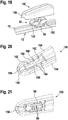
- a wiper blade 10 in a flat-beam construction is constructed from a wiper strip 12, two parallel juxtaposed spring rails 24, two end caps 38 and a connection element 52.
- the wiper strip 12 has a wiper lip 14, which is connected via a tilting web 16 with a header 18. This has on each longitudinal side on an outwardly open longitudinal groove, are inserted into the spring rails 24. Between the longitudinal grooves 20 remains a web 22.
- the spring rails 24 are laterally and frontally a little way from the longitudinal grooves 20 before.
- the end caps 38 are guided with guide profiles 46 and the connecting element 52 with guide profiles 54.
- end caps 38 on the spring rails 24 have on each longitudinal side a lateral open recess 28, which are arranged mirror-symmetrically to a central longitudinal plane 168.
- locking lugs 42 which are integrally formed on the inner sides of side walls 40 of the end cap 38 in the region of the guide profiles 46.
- the end of the longitudinal grooves 20 part of the spring rails 24 tapers via bevels 30 to a narrow end 32. This widens in this area, a gap 36 between the spring rails 24, in which a distance cam 44 engages the front side. This is formed on an end wall of the end cap 38 and holds the ends of the spring strips 24 at a distance.
- spacer cam 44 may be formed on the inner end face of the end cap 38, which engage in corresponding end-side recesses 34 of the spring rails 24.
- the bevels 30, the narrow ends 32 and the recesses 34 are mirror-symmetrical to the longitudinal center plane 168, so that the spring rails 24 can be unmistakably mounted on both sides of the wiper blade 10.
- the end caps 38 have a top wall 48 which interconnects the guide profiles 46 and those on its outside has a title block 50 for company information, type and other information.
- the spring rails 24 have recesses 26 for the connection element 52. These are also arranged on both longitudinal sides of each spring rail 24 symmetrical to the longitudinal center plane 168. In the recesses 26 on the outer longitudinal sides of the spring rails 24 engage locking cams 80, which are provided in grooves 82 of the guide profiles 54, and suitably in the middle.
- the lower flank 84 of the groove 82 is convex, spherical or roof-shaped, so that the pre-curved spring rail 24 is not obstructed, if it adapts to the different radii of curvature of a vehicle window, not shown.
- the connection element 52 (FIG. Fig.
- the connecting element 52 has an open hub, which consists of fixed clip parts 70 in the side walls 56 and a bearing part 76 which is provided on spring tongues 72, 74.
- the opening of the hub 70, 76 lies on the side facing away from the wiper strip 12.
- the open hub 70, 76 serves to support an axle 110, 166 of a wiper arm or an axle 132 of an adapter element 120.
- the only slightly resilient clip parts 70 ensure good guidance of the wiper blade 10 in the longitudinal direction and in the direction of the wiper strip 12, ie in FIG the main load directions, while the bearing member 76 on the spring tongues 72, 74 against sufficient fixation the contact pressure of an adapter element 120 of a wiper arm 150 ensures.
- the wiper arm 108 has a U-shaped cross-sectional profile with two side walls 112, between which a hinge axis 110 is fixedly arranged at the end. This is used when mounting in mounting direction 119 transversely to the wiper blade 10 in the open hub 70, 76, wherein the opening of the open hub 70, 76 closed by a locking cap 88 and thus the wiper arm 108 is additionally secured.
- the locking cap 88 has inwardly open, in cross-section U-shaped guide profiles 92, with which it is longitudinally displaceably guided in the assembly direction 118 in the longitudinal direction of the wiper blade 10 on the outer contour of the guide profile 54 of the connecting element 52. It has two side walls 96 which are interconnected by a top wall 95 and an end wall 94. On the inside of the top wall 95, a detent 98 is provided, which cooperates with a latching hook 64, which is integrally formed on the end face 60 at the bottom 62 of the connecting element 52. Approximately in extension of the side walls 96, the locking cap 88 has slightly inwardly offset cheeks 90, which have slots 102. These have on a wiper arm 108 facing the end of a mounting opening 100 for a hinge axis 110 of the wiper arm 108, while the other end of the slot 102 is formed as a locking part 104.
- the locking cap 88 is in an open position ( Fig. 10 ), in which the mounting opening 100, the open hub 70, 76 releases, so that the wiper arm 108 can be mounted with its hinge axis 110.
- the locking cap 88 is moved in the mounting direction 118 parallel to the longitudinal direction of the wiper blade 10 until the catch 98 engages the latching hook 64, and the locking part 104 of the slot 102, the open hub 70, 76 closes.
- the front side 114 of the wiper arm 108 adjoins a mating surface 116 of the locking cap 88, resulting in a closed, low-noise design.
- the end face 114 and the counter surface 116 which result from the offset of the cheeks 90 to the remaining side walls 96, are curved coaxially to the hinge axis 110.
- the cheeks 90 of the locking cap 88 have at their ends, which face the wiper arm 108, inwardly angled guide claws 91. These engage in the mounting in lateral guide grooves 78 of the connecting element 52 a.
- a recess 106 into which a tool, such as a screwdriver can be used.
- the wiper blade 10 in the embodiment according to Fig. 13 to 18 has an adapter element 120 with two side walls 124, which are interconnected by a bridge 126, an axis 132, a transverse wall 128 and an end cap 122.
- the bridge 126 has on its side facing the connecting element 52 a cam 127 which engages in the mounted state in the recess 67 of the transverse wall 66 and thus prevents incorrect assembly.
- the axle 132 is inserted into the open hub 70, 76 of the connection element 52.
- the adapter member 120 has on the inner sides of its side walls 124 guide surfaces 134, 136, which together with guide surfaces 152 to the Outer sides of the side walls 56 of the connecting element 52 provide for the lateral guidance of the adapter element 120.
- the end cap 122 has on the inside a bearing element 138 in the form of mutually parallel longitudinally extending ribs, which are formed on its outer contour as a bearing roller.
- a wiper arm 140 has a U-shaped cross-sectional profile, whose top wall 146 is extended at the end face 142. The extension is converted into a bearing bracket 144.
- the bearing bracket 114 is inserted under the end cap 122 and includes the bearing member 138 over part of its circumference, so that a pivot bearing between the wiper blade 10 and the wiper arm 140 is formed.
- spring detents 130 are integrally formed on the adapter element, which engage in the mounting in recesses 148 of the wiper arm 140.
- the spring detents 130 are adapted to the recesses 148 so that a sufficient pivoting movement is possible between the wiper blade 10 and the wiper arm 140.
- the spring catches 130 can be pressed elastically inwards, whereby the wiper arm 140 is released and can be pulled out of the end cap 122 with a pivoting movement by about 90 degrees.
- Fig. 19 to 21 has a wiper arm 150, which has a U-shaped cross-sectional profile at least at its wiper blade end, the end of which is closed by a rounded end wall 156 except for a recess 158 for the head strip 18 of the wiper strip 12.
- the recess 158 is dimensioned such that a sufficient pivoting movement of the wiper blade 10 relative to the wiper arm 150 is possible is.
- This has side walls 154, between which mutually parallel longitudinal walls 160 are provided with guide surfaces 162. Between these, the connection element 52 is received.
- the longitudinal walls 160 are interconnected by an axle 166. This engages in the assembly in the open axis 70, 76 of the connecting element 52 and thus forms a pivot bearing for the wiper blade 10th
Landscapes
- Engineering & Computer Science (AREA)
- Mechanical Engineering (AREA)
- Ink Jet (AREA)
- Massaging Devices (AREA)
- Structures Of Non-Positive Displacement Pumps (AREA)
- Power Steering Mechanism (AREA)
- Cleaning In General (AREA)
- Blinds (AREA)
Abstract
Description
Die Erfindung geht von einem Wischblatt nach dem Oberbegriff des Anspruchs 1 aus.The invention is based on a wiper blade according to the preamble of claim 1.
Aus der
Die Führungsprofile der Endkappen haben Vorsprünge mit Löchern, die quer zu den Nuten in den Führungsprofilen der Endkappe verlaufen und Aussparungen an den Außenseiten der Federschienen im montierten Zustand überdecken. Im geringen Abstand zu diesen Aussparungen sind an den Federschienen weitere Aussparungen vorgesehen, die zu Löchern an den Enden der Führungsprofile des Trägers passend angeordnet sind. Schenkel eines haarnadelförmigen Bügels werden durch die Löcher und die entsprechenden Ausnehmungen gesteckt, sodass der Träger, die Federschienen und die Endkappen formschlüssig zusammengefügt sind. Zwei einander gegenüberliegende Bügel der beiden Federschienen sind durch einen Quersteg zu einem Verbindungselement verbunden.The guide profiles of the end caps have projections with holes that are transverse to the grooves in the guide profiles of the end cap and cover recesses on the outer sides of the spring rails in the mounted state. At a small distance to these recesses are on the spring rails more Recesses provided, which are arranged to holes at the ends of the guide profiles of the wearer. Legs of a hairpin-shaped bracket are inserted through the holes and the corresponding recesses, so that the carrier, the spring rails and the end caps are positively joined together. Two opposite brackets of the two spring rails are connected by a transverse web to a connecting element.
Aus der
Zweckmäßigerweise ist an dem Quersteg ein Pin angeordnet, durch den die Wischleiste gegenüber den Federschienen und den Endkappen fixiert ist, indem der Pin im montierten Zustand mit einer unteren Kante gegen die Kopfleiste der Wischleiste drückt.Conveniently, a pin is arranged on the transverse web, by means of which the wiper strip is fixed relative to the spring rails and the end caps, in that the pin in the installed state presses against the head strip of the wiper strip with a lower edge.
Nach der Erfindung weisen die Federschienen an ihren inneren, einander zugewandten Längsseiten Aussparungen auf, die spiegelbildlich zu den Aussparungen an den äußeren Längsseiten angeordnet sind. Dadurch können die Federschienen unverwechselbar auf beiden Seiten der Wischleiste montiert werden. In einer Ausgestaltung der Erfindung besitzen die Endkappen Rastnasen, die in die Aussparungen an den äußeren Längsseiten der Federschienen eingreifen. Somit können zusätzliche Bügelteile entfallen.According to the invention, the spring rails on their inner, mutually facing longitudinal sides recesses, which are arranged in mirror image to the recesses on the outer longitudinal sides. As a result, the spring rails can be unmistakably mounted on both sides of the wiper strip. In one embodiment of the invention, the end caps have latching lugs which engage in the recesses on the outer longitudinal sides of the spring rails. Thus, additional bracket parts can be omitted.
Nach einer weiteren Ausgestaltung der Erfindung besitzen die Federschienen im Bereich des Distanznockens schmale Enden, sodass der Spalt zwischen ihnen in diesem Bereich breiter ist, als auf seiner übrigen Länge. Die schmalen Enden sind symmetrisch zur Längsmittelebene der jeweiligen Federschiene ausgebildet, sodass auch hierbei eine unverwechselbare Montage gewährleistet ist. Der breite Spalt an den Enden der Federschienen ermöglicht einen breiteren Distanznocken, der im Betrieb eine ausreichende Steifigkeit und Festigkeit besitzt. Anstelle des Distanznockens zwischen den Federschienen oder zusätzlich zu diesem, kann die Endkappe weitere Distanznocken aufweisen, die in entsprechende Aussparungen an den Stirnseiten der Federschienen eingreifen. Auch diese sind zweckmäßigerweise jeweils symmetrisch zu der Längsmittelebene der zugehörigen Federschiene angeordnet.According to a further embodiment of the invention, the spring rails have narrow ends in the region of the distance cam, so that the gap between them is wider in this area than on its remaining length. The narrow ends are formed symmetrically to the longitudinal center plane of the respective spring rail, so that here, a unique assembly is guaranteed. The wide gap at the ends of the spring rails allows for a wider distance cam that has sufficient rigidity and strength during operation. Instead of the distance cam between the spring rails or in addition to this, the end cap may have further distance cams which engage in corresponding recesses on the end faces of the spring rails. These are expediently arranged in each case symmetrically to the longitudinal center plane of the associated spring rail.
Um ein Anschlusselement im mittleren Bereich der Länge der Federschienen zu fixieren, ist es zweckmäßig, dass die Federschienen dort an ihren beiden Längsseiten Aussparungen aufweisen, die spiegelbildlich zueinander angeordnet sind, und in die mindestens ein Rastnocken eines Anschlusselements eingreift. Der Rastnocken ist dabei vorteilhaft in einer Nut eines Führungsprofils vorgesehen, das auf einem aus der Längsnut vorstehenden Teil der Federschiene sitzt.In order to fix a connecting element in the central region of the length of the spring rails, it is expedient that the spring rails have recesses there on their two longitudinal sides, which are arranged in mirror image of one another, and engages in the at least one locking cam of a connection element. The locking cam is advantageously provided in a groove of a guide profile, which sits on a protruding from the longitudinal groove part of the spring rail.
Zum gelenkigen Verbinden eines Wischarms mit dem Anschlusselement besitzt dieses eine Nabe, die zu einer von der Wischleiste abgewandten Seite offen ist, und aus festen Klippteilen in den Seitenwänden des Anschlusselements und einem Lagerteil gebildet wird, das an Federzungen angeordnet ist. Durch die festen Klippteile wird eine präzise Führung und Lagerung einer Achse des Wischarms gewährleistet, die von der offenen Nabe aufgenommen wird, während durch das Lagerteil an den Federzungen die Achse des Wischarms in Form einer Klippverbindung in der Nabe gehalten wird. Das Lagerteil kann auf Grund seiner größeren Nachgiebigkeit die Achse des Wischarms zur offenen Seite der Nabe hin auf einem größeren Umfangsbereich umfassen als die festen Klippteile. Um die Wischleiste relativ zum Anschlusselement in Längsrichtung zu fixieren, ist gemäß einer weiteren Ausgestaltung vorgesehen, dass das Anschlusselement an seiner der Kopfleiste zugewandten Seite einen Fixiernocken besitzt, der in montiertem Zustand gegen die Kopfleiste drückt.For articulated connection of a wiper arm with the connecting element, this has a hub which is open to a side facing away from the wiper strip side, and is formed of fixed clip parts in the side walls of the connecting element and a bearing part, which is arranged on spring tongues. The fixed clip parts ensure precise guidance and support of an axis of the wiper arm which is received by the open hub, while the axis of the wiper arm is held in the hub by the bearing part on the spring tongues in the form of a clip connection. Due to its greater compliance, the bearing part may comprise the axis of the wiper arm towards the open side of the hub over a larger circumferential area than the fixed clip parts. In order to fix the wiper strip relative to the connection element in the longitudinal direction, it is provided according to a further embodiment that the connection element has a fixing cam on its side facing the head strip, which presses in the assembled state against the head strip.
Das Anschlusselement mit seiner offenen Nabe wird im montierten Zustand von einer Verriegelungskappe abgedeckt. Diese ist auf der Außenkontur des Führungsprofils des Anschlusselements geführt. Zum Verriegeln weist sie vorteilhafterweise in ihren Wangen parallel zu ihren Führungsprofilen verlaufende Langlöcher auf, die jeweils an einem einem Wischarm zugewandten Ende eine Montageöffnung für eine Gelenkachse des Wischarms besitzen, während das andere Ende als Verriegelungsteil ausgebildet ist. Während der Montage wird die Achse des Wischarms durch die Montageöffnungen in die offene Nabe eingesetzt. Daraufhin wird die Verriegelungskappe weiter in Längsrichtung verschoben, sodass der Verriegelungsteil die Montageöffungen verschließt. In der Schließstellung ist es zweckmäßig, dass die Verriegelungskappe an der Innenseite eine Arretierung besitzt, die mit einem Rasthaken an der dem Wischarm abgewandten Stirnseite des Verbindungselements zusammenwirkt. Dadurch ist die Verriegelungskappe in der Schließstellung blockiert. Der Rasthaken kann zur Demontage zurückgedrückt werden, sodass die Verriegelungskappe in eine Öffnungsposition zurückgeschoben werden kann.The connecting element with its open hub is covered by a locking cap in the mounted state. This is guided on the outer contour of the guide profile of the connection element. For locking it has advantageously in their cheeks parallel to their guide profiles extending slots, each having a mounting opening for a hinge axis of the wiper arm on a wiper arm end, while the other end formed as a locking part is. During assembly, the axis of the wiper arm is inserted through the mounting holes in the open hub. Thereafter, the locking cap is further displaced in the longitudinal direction, so that the locking member closes the mounting apertures. In the closed position, it is expedient that the locking cap on the inside has a lock which cooperates with a latching hook on the end face of the connecting element facing away from the wiper arm. As a result, the locking cap is blocked in the closed position. The locking hook can be pushed back for disassembly, so that the locking cap can be pushed back into an open position.
Gemäß einer Ausgestaltung der Erfindung ist die Verriegelungskappe auf der Außenkontur des Führungsprofils des Anschlusselements geführt, wobei das Anschlusselement zum größten Teil von der Verriegelungskappe und der Rest von dem Wischarmprofil abgedeckt werden, das sich bündig an die Verriegelungskappe anschließt. Die Verriegelungskappe hat an dem dem Wischarm zugewandten Ende an ihren Wangen nach innen abgewinkelte Führungsklauen, die in nach außen weisende Führungsnuten an den Seitenwänden des Anschlusselements eingreifen. Durch die Führungsklauen stützt sich die Verriegelungskappe zusätzlich zu ihrem Führungsprofil an dem Anschlusselement ab. Dadurch ergibt sich eine gute Verbindung zwischen diesen beiden Bauteilen.According to one embodiment of the invention, the locking cap is guided on the outer contour of the guide profile of the connecting element, wherein the connecting element are covered for the most part by the locking cap and the rest of the wiper arm profile, which is flush with the locking cap. The locking cap has at the end facing the wiper arm at its cheeks inwardly angled guide claws which engage in outwardly facing guide grooves on the side walls of the connecting element. By the guide claws, the locking cap is supported in addition to its guide profile on the connection element. This results in a good connection between these two components.
Um das Wischblatt mit einer Wischarmart zu kombinieren, bei der an der Stirnseite des Wischarms eine Lagerlasche angeformt ist, ist an dem Anschlusselement gemäß einer Ausgestaltung der Erfindung ein Adapterelement befestigt, das mit einer Achse zwischen seinen Seitenwänden in die offene Nabe des Anschlusselements eingesetzt ist und durch Führungsflächen an den Innenseiten seiner Seitenwände seitlich geführt ist, wobei in einer Stirnkappe des Adapterelements ein Lagerelement für den Wischarm vorgesehen ist. Das Lagerelement kann zweckmäßigerweise aus mehreren parallel zueinander, in Längsrichtung angeordneten Rippen bestehen, deren Außenkonturen eine Lagerwalze bilden. Diese wird von der Lagerlasche des Wischarms im montierten Zustand teilweise umfasst, sodass das Wischblatt relativ zum Wischarm begrenzt schwenkbar ist.In order to combine the wiper blade with a Wischarmart, in which on the front side of the wiper arm a bearing lug is formed, is attached to the connection element according to an embodiment of the invention, an adapter element, which with an axis between its side walls in the open hub of the Connection element is inserted and is guided laterally by guide surfaces on the inner sides of its side walls, wherein a bearing element for the wiper arm is provided in an end cap of the adapter element. The bearing element can expediently consist of a plurality of mutually parallel, longitudinally arranged ribs whose outer contours form a bearing roller. This is partially covered by the bearing bracket of the wiper arm in the assembled state, so that the wiper blade is pivotally limited relative to the wiper arm.
Gemäß einer Ausgestaltung der Erfindung weist das Adapterelement des Wischblatts in Verlängerung seiner Seitenwände Federrasten auf, die im montierten Zustand in Aussparungen des Wischarms einrasten. Die Federrasten und die Aussparungen sind so dimensioniert, dass sie die Schwenkbewegung zwischen dem Wischblatt und dem Wischarm nicht behindern.According to one embodiment of the invention, the adapter element of the wiper blade in extension of its side walls on spring detents, which engage in recesses of the wiper arm in the mounted state. The spring catches and the recesses are dimensioned so that they do not hinder the pivoting movement between the wiper blade and the wiper arm.
Schließlich kann das Wischblatt mit einer dritten Art von Wischarmen gelenkig verbunden werden, bei der der Wischarm an seinem dem Wischblatt zugewandten Ende ein u-förmiges Querschnittprofil aufweist, das durch eine Stirnwand in Längsrichtung bis auf eine Aussparung für die Kopfleiste abgeschlossen ist. In dem Innenraum des u-förmigen Querschnittprofils sind etwa parallel zu den Seitenwänden in Längsrichtung verlaufende Längswände vorgesehen, die an ihren Innenseiten Führungsflächen für das Anschlusselement des Wischblatts besitzen sowie eine Achse tragen und außen durch Querrippen an den Seitenwänden angeschlossen sind. Bei dieser Lösung wird das Anschlusselement vom Wischarm abgedeckt, wobei die Aussparung in der Stirnseite eine ausreichende Schwenkbewegung zwischen dem Wischblatt und dem Wischarm zulässt.Finally, the wiper blade can be hingedly connected to a third type of wiper arms, in which the wiper arm has a U-shaped cross-sectional profile at its end facing the wiper blade, which is closed by an end wall in the longitudinal direction except for a recess for the head strip. In the interior of the U-shaped cross-sectional profile extending longitudinally parallel to the side walls in the longitudinal direction longitudinal walls are provided, which have on their inner sides guide surfaces for the connection element of the wiper blade and carry an axis and are connected externally by transverse ribs on the side walls. In this solution, the connection element is covered by the wiper arm, wherein the recess in the front side allows a sufficient pivotal movement between the wiper blade and the wiper arm.
Weitere Vorteile ergeben sich aus der folgenden Zeichnungsbeschreibung. In der Zeichnung sind Ausführungsbeispiele der Erfindung dargestellt. Die Zeichnung, die Beschreibung und die Ansprüche enthalten zahlreiche Merkmale in Kombination. Der Fachmann wird die Merkmale zweckmäßigerweise auch einzeln betrachten und zu sinnvollen weiteren Kombinationen zusammenfassen.Further advantages emerge from the following description of the drawing. In the drawings, embodiments of the invention are shown. The drawing, the description and the claims contain numerous features in combination. The person skilled in the art will expediently also consider the features individually and combine them into meaningful further combinations.
Es zeigen:
- Fig. 1
- eine perspektivische Seitenansicht eines erfindungsgemäßen Wischblatts,
- Fig. 2
- ein Ende eines Wischblatts nach
Fig. 1 in einer Teilexplosionsdarstellung, - Fig. 3
- einen mittleren Teil eines Wischblatts nach
Fig. 1 ohne Anschlusselement, - Fig. 4
- eine Endkappe in perspektivischer Ansicht,
- Fig. 5
- eine Endkappe mit Federschienen in einer Ansicht von unten,
- Fig. 6
- eine perspektivische Ansicht eines Anschlusselements,
- Fig. 7
- eine perspektivische Ansicht des Anschlusselements nach
Fig. 6 von unten, - Fig. 8
- einen Schnitt entsprechend der Linie VIII-VIII in
Fig. 6 , - Fig. 9
- das Anschlusselement nach
Fig. 6 mit einer Verriegelungskappe in einer Explosionsdarstellung, - Fig. 10
- eine perspektivische Teilansicht eines Wischblatts nach
Fig. 1 mit der Verriegelungskappe und einem Wischarm während der Montage, - Fig. 11
- eine perspektivische Ansicht der Verriegelungskappe vom Anschlusselement aus,
- Fig. 12
- eine perspektivische Ansicht der Verriegelungskappe von unten,
- Fig. 13
- eine perspektivische Teilansicht eines Wischblatts mit einem Adapterelement,
- Fig. 14
- ein Wischblatt nach
Fig. 13 mit einem Wischarm während der Montage, - Fig. 15
- ein Wischblatt nach
Fig. 13 mit einem montierten Wischarm, - Fig. 16
- eine perspektivische Ansicht des Adapterelements nach
Fig. 13 , - Fig. 17
- das Adapterelement nach
Fig. 16 in einer Ansicht von unten, - Fig. 18
- das Adapterelement nach
Fig. 16 auf dem Anschlusselement montiert, - Fig. 19
- eine perspektivische Darstellung des Wischblatts mit dem Anschlusselement während der Montage mit einem Wischarm,
- Fig. 20
- eine perspektivische Teilansicht des Wischarms nach
Fig. 19 von unten und - Fig. 21
- eine perspektivische Teilansicht des Wischarms nach
Fig. 20 mit dem Anschlusselement.
- Fig. 1
- a perspective side view of a wiper blade according to the invention,
- Fig. 2
- an end of a wiper blade after
Fig. 1 in a partial explosion representation, - Fig. 3
- a middle part of a wiper blade
Fig. 1 without connecting element, - Fig. 4
- an end cap in perspective view,
- Fig. 5
- an end cap with spring rails in a bottom view,
- Fig. 6
- a perspective view of a connection element,
- Fig. 7
- a perspective view of the connection element according to
Fig. 6 from underneath, - Fig. 8
- a section corresponding to the line VIII-VIII in
Fig. 6 . - Fig. 9
- the connection element after
Fig. 6 with a locking cap in an exploded view, - Fig. 10
- a partial perspective view of a wiper blade
Fig. 1 with the locking cap and a wiper arm during assembly, - Fig. 11
- a perspective view of the locking cap from the connection element,
- Fig. 12
- a perspective view of the locking cap from below,
- Fig. 13
- a partial perspective view of a wiper blade with an adapter element,
- Fig. 14
- a wiper blade after
Fig. 13 with a wiper arm during assembly, - Fig. 15
- a wiper blade after
Fig. 13 with a mounted wiper arm, - Fig. 16
- a perspective view of the adapter element according to
Fig. 13 . - Fig. 17
- the adapter element after
Fig. 16 in a view from below, - Fig. 18
- the adapter element after
Fig. 16 mounted on the connection element, - Fig. 19
- a perspective view of the wiper blade with the connection element during assembly with a wiper arm,
- Fig. 20
- a partial perspective view of the wiper arm after
Fig. 19 from below and - Fig. 21
- a partial perspective view of the wiper arm after
Fig. 20 with the connection element.
Ein Wischblatt 10 in Flachbalkenbauweise ist aus einer Wischleiste 12, zwei parallelen nebeneinander liegenden Federschienen 24, zwei Endkappen 38 und einem Anschlusselement 52 aufgebaut. Die Wischleiste 12 besitzt eine Wischlippe 14, die über einen Kippsteg 16 mit einer Kopfleiste 18 verbunden ist. Diese weist an jeder Längsseite eine nach außen hin offene Längsnut auf, in die Federschienen 24 eingelegt werden. Zwischen den Längsnuten 20 verbleibt ein Steg 22. Die Federschienen 24 stehen seitlich und stirnseitig ein Stück weit aus den Längsnuten 20 vor. Auf den seitlich vorstehenden Teilen der Federschienen 24 sind die Endkappen 38 mit Führungsprofilen 46 und das Anschlusselement 52 mit Führungsprofilen 54 geführt.A
Zum Fixieren der Endkappen 38 auf den Federschienen 24 besitzen diese an jeder Längsseite eine seitliche offene Aussparung 28, die spiegelsymmetrisch zu einer Mittellängsebene 168 angeordnet sind. In die Aussparungen 28 an den äußeren Längsseiten der Federschienen 24 greifen Rastnasen 42, die an den Innenseiten von Seitenwänden 40 der Endkappe 38 im Bereich der Führungsprofile 46 angeformt sind. Der aus den Längsnuten 20 stirnseitige Teil der Federschienen 24 verjüngt sich über Schrägen 30 zu einem schmalen Ende 32. Dadurch erweitert sich in diesem Bereich ein Spalt 36 zwischen den Federschienen 24, in den ein Distanznocken 44 stirnseitig eingreift. Dieser ist an einer Stirnwand der Endkappe 38 angeformt und hält die Enden der Federleisten 24 auf Distanz. Anstelle des Distanznockens 44 oder zusätzlich dazu können weitere Distanznocken 45 an der inneren Stirnseite der Endkappe 38 angeformt sein, die in entsprechende stirnseitige Aussparungen 34 der Federschienen 24 eingreifen. Die Schrägen 30, die schmalen Enden 32 und die Aussparungen 34 sind spiegelsymmetrisch zur Längsmittelebene 168 ausgebildet, sodass die Federschienen 24 unverwechselbar auf beiden Seiten des Wischblatts 10 montiert werden können. Die Endkappen 38 besitzen eine Deckwand 48, die die Führungsprofile 46 miteinander verbindet und die an ihrer Außenseite ein Schriftfeld 50 für Firmenangaben, Typ und sonstige Hinweise besitzt.For fixing the end caps 38 on the spring rails 24, they have on each longitudinal side a lateral
Im mittleren Bereich des Wischblatts 10 besitzen die Federschienen 24 Aussparungen 26 für das Anschlusselement 52. Diese sind ebenfalls an beiden Längsseiten einer jeden Federschiene 24 symmetrisch zur Längsmittelebene 168 angeordnet. In die Aussparungen 26 an den äußeren Längsseiten der Federschienen 24 greifen Rastnocken 80, die in Nuten 82 der Führungsprofile 54 vorgesehen sind, und zwar zweckmäßigerweise in der Mitte. Die untere Flanke 84 der Nut 82 ist konvex, ballig oder dachförmig ausgeführt, sodass die vorgekrümmte Federschiene 24 nicht behindert wird, wenn sich diese den unterschiedlichen Krümmungsradien einer nicht dargestellten Fahrzeugscheibe anpasst. Das Anschlusselement 52 (
Der Wischarm 108 besitzt ein u-förmiges Querschnittprofil mit zwei Seitenwänden 112, zwischen denen am Ende eine Gelenkachse 110 fest angeordnet ist. Diese wird bei der Montage in Montagerichtung 119 quer zum Wischblatt 10 in die offene Nabe 70, 76 eingesetzt, wobei die Öffnung der offenen Nabe 70, 76 durch eine Verriegelungskappe 88 geschlossen und somit der Wischarm 108 zusätzlich gesichert wird.The
Die Verriegelungskappe 88 besitzt nach innen offene, im Querschnitt u-förmige Führungsprofile 92, mit denen sie in Montagerichtung 118 in Längsrichtung des Wischblatts 10 auf der Außenkontur des Führungsprofils 54 des Anschlusselements 52 längsverschieblich geführt ist. Sie besitzt zwei Seitenwände 96, die durch eine Deckwand 95 und eine Stirnwand 94 miteinander verbunden sind. An der Innenseite der Deckwand 95 ist eine Arretierung 98 vorgesehen, die mit einem Rasthaken 64 zusammenwirkt, der an der Stirnseite 60 am Boden 62 des Anschlusselements 52 angeformt ist. Etwa in Verlängerung der Seitenwände 96 besitzt die Verriegelungskappe 88 etwas nach innen versetzt Wangen 90, die Langlöcher 102 aufweisen. Diese besitzen an einem dem Wischarm 108 zugewandten Ende eine Montageöffnung 100 für eine Gelenkachse 110 des Wischarms 108, während das andere Ende des Langlochs 102 als Verriegelungsteil 104 ausgebildet ist.The locking
Bei der Montage befindet sich die Verriegelungskappe 88 in einer Öffnungsstellung (
Das Wischblatt 10 in der Ausführung nach
Die Stirnkappe 122 besitzt an der Innenseite ein Lagerelement 138 in Form von parallel zueinander in Längsrichtung verlaufenden Rippen, die an ihrer Außenkontur als Lagerwalze ausgebildet sind. Ein Wischarm 140 hat ein u-förmiges Querschnittprofil, dessen Deckwand 146 an der Stirnseite 142 verlängert ist. Die Verlängerung ist zu einer Lagerlasche 144 umgeformt. Bei der Montage wird die Lagerlasche 114 unter die Stirnkappe 122 gesteckt und umfasst das Lagerelement 138 über einen Teil seines Umfangs, sodass ein Schwenklager zwischen dem Wischblatt 10 und dem Wischarm 140 gebildet wird.The
In Verlängerung der Seitenwände 124 über die Querwand 128 hinaus sind an dem Adapterelement 120 Federrasten 130 angeformt, die bei der Montage in Aussparungen 148 des Wischarms 140 einrasten. Dabei sind die Federrasten 130 auf die Aussparungen 148 so abgestimmt, dass zwischen dem Wischblatt 10 und dem Wischarm 140 eine ausreichende Schwenkbewegung möglich ist. Zur Demontage des Adapterelements 120 können die Federrasten 130 elastisch nach innen gedrückt werden, wodurch der Wischarm 140 frei gegeben wird und mit einer Schwenkbewegung um etwa 90 Grad aus der Stirnkappe 122 gezogen werden kann.In extension of the
Die Ausführung nach
Claims (14)
Applications Claiming Priority (2)
| Application Number | Priority Date | Filing Date | Title |
|---|---|---|---|
| DE102007058091A DE102007058091A1 (en) | 2007-12-03 | 2007-12-03 | wiper blade |
| EP08857070A EP2229301B1 (en) | 2007-12-03 | 2008-10-14 | Wiper blade |
Related Parent Applications (1)
| Application Number | Title | Priority Date | Filing Date |
|---|---|---|---|
| EP08857070.0 Division | 2008-10-14 |
Publications (1)
| Publication Number | Publication Date |
|---|---|
| EP2450244A1 true EP2450244A1 (en) | 2012-05-09 |
Family
ID=40202960
Family Applications (2)
| Application Number | Title | Priority Date | Filing Date |
|---|---|---|---|
| EP08857070A Active EP2229301B1 (en) | 2007-12-03 | 2008-10-14 | Wiper blade |
| EP12153561A Withdrawn EP2450244A1 (en) | 2007-12-03 | 2008-10-14 | Wiper blade |
Family Applications Before (1)
| Application Number | Title | Priority Date | Filing Date |
|---|---|---|---|
| EP08857070A Active EP2229301B1 (en) | 2007-12-03 | 2008-10-14 | Wiper blade |
Country Status (7)
| Country | Link |
|---|---|
| EP (2) | EP2229301B1 (en) |
| CN (1) | CN101883701B (en) |
| AT (1) | ATE553967T1 (en) |
| BR (1) | BRPI0820038B1 (en) |
| DE (1) | DE102007058091A1 (en) |
| PL (1) | PL2229301T3 (en) |
| WO (1) | WO2009071372A1 (en) |
Families Citing this family (23)
| Publication number | Priority date | Publication date | Assignee | Title |
|---|---|---|---|---|
| DE102010042096A1 (en) * | 2009-10-09 | 2011-04-14 | Robert Bosch Gmbh | wiper blade |
| DE102009046776A1 (en) * | 2009-11-17 | 2011-05-19 | Robert Bosch Gmbh | Wiper blade in flat bar construction |
| ES2428821T3 (en) * | 2009-11-17 | 2013-11-11 | Robert Bosch Gmbh | Adapter for connecting a connecting element at the end of a windshield wiper arm with a windshield wiper blade, particularly of the flat bar construction type |
| EP2360070B1 (en) * | 2010-02-12 | 2014-09-10 | Unipoint Electric MFG. Co., Ltd. | Wiper connector |
| CA2818258C (en) * | 2010-11-24 | 2016-02-23 | Trico Products Corporation | Beam blade wiper assembly having self-locking end cap |
| DE102010062933A1 (en) * | 2010-12-13 | 2012-06-14 | Robert Bosch Gmbh | wiper device |
| DE102010063019A1 (en) | 2010-12-14 | 2012-06-14 | Robert Bosch Gmbh | Wiper blade adapter device |
| DE102011004632A1 (en) * | 2011-02-24 | 2012-08-30 | Robert Bosch Gmbh | Wiper blade for cleaning windows, especially of motor vehicles |
| DE112014004175T5 (en) * | 2013-09-11 | 2016-05-25 | Asmo Co., Ltd. | Wiper blade and method of making the wiper blade |
| FR3039112B1 (en) * | 2015-07-24 | 2019-01-25 | Valeo Systemes D'essuyage | DEVICE FOR FIXING A BLADE OF A WIPER BROOM |
| FR3043618B1 (en) * | 2015-11-17 | 2017-12-15 | Valeo Systemes Dessuyage | TRAINING ARM ASSEMBLY AND CONNECTOR FOR WIPER. |
| FR3043617B1 (en) * | 2015-11-17 | 2017-12-08 | Valeo Systemes Dessuyage | CAP COMPRISING A CONNECTOR FOR A WIPER BLADE OF A MOTOR VEHICLE. |
| FR3043619B1 (en) | 2015-11-17 | 2019-05-24 | Valeo Systemes D'essuyage | ADAPTER, CONNECTOR AND ASSEMBLY FORMED OF SUCH A CONNECTOR AND SUCH ADAPTER FOR A WIPER. |
| DE102015226764A1 (en) * | 2015-12-28 | 2017-06-29 | Robert Bosch Gmbh | Wiper blade device |
| FR3051748B1 (en) * | 2016-05-31 | 2018-06-15 | Valeo Systemes D'essuyage | EXTERMITY END OF A WIPING BRUSH AND CORRESPONDING WIPING ASSEMBLY |
| CN107415895A (en) * | 2017-09-06 | 2017-12-01 | 贵阳万江航空机电有限公司 | The fit structure and replacing rubber strip method of a kind of flat wiper blade sliver and end cap |
| WO2019161348A1 (en) | 2018-02-19 | 2019-08-22 | Trico Products Corporation | Windshield wiper arm adapter, coupler and assembly |
| USD896156S1 (en) | 2019-04-16 | 2020-09-15 | Trico Products Corporation | Coupler for windshield wiper |
| USD904275S1 (en) | 2019-04-16 | 2020-12-08 | Trico Products Corporation | Adapter for windshield wiper arm |
| USD895523S1 (en) | 2019-04-16 | 2020-09-08 | Trico Products Corporation | Coupler for windshield wiper |
| FR3103767B1 (en) * | 2019-11-29 | 2021-10-29 | Valeo Systemes Dessuyage | Cover of a glass surface wiping device |
| JP7365959B2 (en) * | 2020-04-27 | 2023-10-20 | 株式会社ミツバ | wiper blade |
| US11801807B1 (en) * | 2022-10-18 | 2023-10-31 | Danyang Upc Auto Parts Co., Ltd. | End cap assembly structure of windshield wiper |
Citations (9)
| Publication number | Priority date | Publication date | Assignee | Title |
|---|---|---|---|---|
| DE19860644A1 (en) * | 1998-12-29 | 2000-07-06 | Bosch Gmbh Robert | Device for the articulated connection of a wiper blade for windows of motor vehicles with a wiper arm and method for producing this connection |
| DE19951363A1 (en) * | 1999-10-26 | 2001-05-03 | Bosch Gmbh Robert | Wiper blade for windows of motor vehicles |
| DE10058208A1 (en) * | 2000-11-23 | 2002-07-11 | Valeo Auto Electric Gmbh | wiper device |
| JP2005059644A (en) * | 2003-08-08 | 2005-03-10 | Nippon Wiper Blade Co Ltd | Wiper blade |
| DE102004019158A1 (en) | 2004-04-21 | 2005-11-10 | Robert Bosch Gmbh | wiper blade |
| DE102004019157A1 (en) * | 2004-04-21 | 2005-11-10 | Robert Bosch Gmbh | wiper blade |
| US20060117515A1 (en) * | 2002-11-26 | 2006-06-08 | Andreas Fink | Device for detachably linking a wiper blade with a driven wiper arm |
| DE102004058684A1 (en) | 2004-12-06 | 2006-06-14 | Robert Bosch Gmbh | wiper blade |
| DE202006012252U1 (en) * | 2005-08-10 | 2006-10-12 | Flex Wiper Enterprises Co., Ltd. | Cartilaginous wiper has connection device whose lower portion is engaged with pair of elastic rails for allowing both ends to extend freely and independently |
Family Cites Families (5)
| Publication number | Priority date | Publication date | Assignee | Title |
|---|---|---|---|---|
| FR2281858A1 (en) * | 1974-08-14 | 1976-03-12 | Sev Marchal | Windscreen wiper blade reinforced by metal - has auxiliary stirrup pieces engaging plastic plates recessed in blade |
| US7159269B2 (en) * | 2003-08-26 | 2007-01-09 | Albert Lee | Backing strip for windshield wiper |
| GB2416675B (en) * | 2004-07-04 | 2006-08-16 | Shu-Lan Ku | Windscreen wipers |
| WO2007122569A2 (en) * | 2006-04-21 | 2007-11-01 | Teklas Kaucuk Sanayi Ve Ticaret A.S. | End caps used in windshield wipers for vehicles |
| DE602006008281D1 (en) * | 2006-05-19 | 2009-09-17 | Federal Mogul Sa | wiper device |
-
2007
- 2007-12-03 DE DE102007058091A patent/DE102007058091A1/en not_active Withdrawn
-
2008
- 2008-10-14 EP EP08857070A patent/EP2229301B1/en active Active
- 2008-10-14 EP EP12153561A patent/EP2450244A1/en not_active Withdrawn
- 2008-10-14 PL PL08857070T patent/PL2229301T3/en unknown
- 2008-10-14 CN CN2008801189475A patent/CN101883701B/en active Active
- 2008-10-14 WO PCT/EP2008/063800 patent/WO2009071372A1/en active Application Filing
- 2008-10-14 BR BRPI0820038A patent/BRPI0820038B1/en not_active IP Right Cessation
- 2008-10-14 AT AT08857070T patent/ATE553967T1/en active
Patent Citations (9)
| Publication number | Priority date | Publication date | Assignee | Title |
|---|---|---|---|---|
| DE19860644A1 (en) * | 1998-12-29 | 2000-07-06 | Bosch Gmbh Robert | Device for the articulated connection of a wiper blade for windows of motor vehicles with a wiper arm and method for producing this connection |
| DE19951363A1 (en) * | 1999-10-26 | 2001-05-03 | Bosch Gmbh Robert | Wiper blade for windows of motor vehicles |
| DE10058208A1 (en) * | 2000-11-23 | 2002-07-11 | Valeo Auto Electric Gmbh | wiper device |
| US20060117515A1 (en) * | 2002-11-26 | 2006-06-08 | Andreas Fink | Device for detachably linking a wiper blade with a driven wiper arm |
| JP2005059644A (en) * | 2003-08-08 | 2005-03-10 | Nippon Wiper Blade Co Ltd | Wiper blade |
| DE102004019158A1 (en) | 2004-04-21 | 2005-11-10 | Robert Bosch Gmbh | wiper blade |
| DE102004019157A1 (en) * | 2004-04-21 | 2005-11-10 | Robert Bosch Gmbh | wiper blade |
| DE102004058684A1 (en) | 2004-12-06 | 2006-06-14 | Robert Bosch Gmbh | wiper blade |
| DE202006012252U1 (en) * | 2005-08-10 | 2006-10-12 | Flex Wiper Enterprises Co., Ltd. | Cartilaginous wiper has connection device whose lower portion is engaged with pair of elastic rails for allowing both ends to extend freely and independently |
Also Published As
| Publication number | Publication date |
|---|---|
| EP2229301A1 (en) | 2010-09-22 |
| BRPI0820038A2 (en) | 2015-05-12 |
| EP2229301B1 (en) | 2012-04-18 |
| ATE553967T1 (en) | 2012-05-15 |
| DE102007058091A1 (en) | 2009-06-04 |
| PL2229301T3 (en) | 2012-09-28 |
| WO2009071372A1 (en) | 2009-06-11 |
| CN101883701A (en) | 2010-11-10 |
| CN101883701B (en) | 2012-08-15 |
| BRPI0820038B1 (en) | 2019-09-10 |
Similar Documents
| Publication | Publication Date | Title |
|---|---|---|
| EP2229301B1 (en) | Wiper blade | |
| EP2321160B1 (en) | Device for the articulated connection of a wiper blade to a wiper arm of a windshield wiper | |
| EP2424755B1 (en) | Connecting apparatus for hinging a joining element rigidly connected to a wiper arm | |
| EP2146877B1 (en) | Connection device for the articulated connection of a wiper blade to a wiper arm | |
| EP2259954B1 (en) | Wiper blade | |
| EP2588352B1 (en) | Connecting device for connecting a wiper arm to a wiper blade in an articulated manner | |
| EP2268513B1 (en) | Wiper blade | |
| EP2678195B1 (en) | Wiper blade | |
| EP1966013B1 (en) | Connection element | |
| EP2326538B1 (en) | Connecting device for the articulated connection of a wiper blade to a wiper arm | |
| EP2040960B1 (en) | Connection element for a wiper blade and wiper blade | |
| EP2552755B1 (en) | Connection device for the articulated connection of a wiper arm to a wiper blade | |
| EP2477853B1 (en) | Wiper blade designed as a flat bar | |
| DE102007016479A1 (en) | connection device | |
| DE102010003269A1 (en) | Adapter for pivotally connecting a connecting element at the end of a wiper arm to a connecting element of a wiper blade | |
| WO2006081893A1 (en) | Device for the pivoting connection of a wiper blade to a wiper arm of a windscreen wiper | |
| EP2179901B1 (en) | Connection device for articulated connection of a wiper blade in flat bar construction with a wiper arm | |
| EP2193963B1 (en) | Wiper blade | |
| DE3119176C2 (en) | Apparatus for connecting a windshield wiper arm to a windshield wiper blade | |
| EP2714476A1 (en) | Wiper blade | |
| DE102008040033A1 (en) | Series of a wiper blade | |
| DE102011089545A1 (en) | Connector for articulated connection of wiper arm with wiper blade to wipe vehicle windscreen, has aperture dimensioned such that longitudinal slot width, connecting element thickness and projection diameter are matched to each other |
Legal Events
| Date | Code | Title | Description |
|---|---|---|---|
| PUAI | Public reference made under article 153(3) epc to a published international application that has entered the european phase |
Free format text: ORIGINAL CODE: 0009012 |
|
| AC | Divisional application: reference to earlier application |
Ref document number: 2229301 Country of ref document: EP Kind code of ref document: P |
|
| AK | Designated contracting states |
Kind code of ref document: A1 Designated state(s): AT BE BG CH CY CZ DE DK EE ES FI FR GB GR HR HU IE IS IT LI LT LU LV MC MT NL NO PL PT RO SE SI SK TR |
|
| STAA | Information on the status of an ep patent application or granted ep patent |
Free format text: STATUS: THE APPLICATION IS DEEMED TO BE WITHDRAWN |
|
| 18D | Application deemed to be withdrawn |
Effective date: 20121110 |