EP2450083B1 - Testobjekt für die Qualitätskontrolle eines Geräts zur Strahlentherapie-Behandlung, sowie Herstellungs- und Anwendungsverfahren dieses Testobjekts - Google Patents
Testobjekt für die Qualitätskontrolle eines Geräts zur Strahlentherapie-Behandlung, sowie Herstellungs- und Anwendungsverfahren dieses Testobjekts Download PDFInfo
- Publication number
- EP2450083B1 EP2450083B1 EP20100189893 EP10189893A EP2450083B1 EP 2450083 B1 EP2450083 B1 EP 2450083B1 EP 20100189893 EP20100189893 EP 20100189893 EP 10189893 A EP10189893 A EP 10189893A EP 2450083 B1 EP2450083 B1 EP 2450083B1
- Authority
- EP
- European Patent Office
- Prior art keywords
- sphere
- test
- fact
- ball
- electron density
- Prior art date
- Legal status (The legal status is an assumption and is not a legal conclusion. Google has not performed a legal analysis and makes no representation as to the accuracy of the status listed.)
- Active
Links
- 238000011282 treatment Methods 0.000 title claims description 53
- 238000001959 radiotherapy Methods 0.000 title claims description 36
- 238000000034 method Methods 0.000 title claims description 15
- 238000003908 quality control method Methods 0.000 title claims description 10
- 238000012360 testing method Methods 0.000 title description 79
- 238000004519 manufacturing process Methods 0.000 title description 4
- 239000000463 material Substances 0.000 claims description 59
- 230000005855 radiation Effects 0.000 claims description 20
- 238000001429 visible spectrum Methods 0.000 claims description 10
- 229920003229 poly(methyl methacrylate) Polymers 0.000 claims description 9
- 239000004926 polymethyl methacrylate Substances 0.000 claims description 9
- 238000010422 painting Methods 0.000 claims description 7
- 239000004033 plastic Substances 0.000 claims description 7
- 229920003023 plastic Polymers 0.000 claims description 7
- WFKWXMTUELFFGS-UHFFFAOYSA-N tungsten Chemical compound [W] WFKWXMTUELFFGS-UHFFFAOYSA-N 0.000 claims description 7
- 229910052721 tungsten Inorganic materials 0.000 claims description 7
- 239000010937 tungsten Substances 0.000 claims description 7
- 230000000007 visual effect Effects 0.000 claims description 7
- 229910052751 metal Inorganic materials 0.000 claims description 6
- 239000002184 metal Substances 0.000 claims description 6
- 229910052782 aluminium Inorganic materials 0.000 claims description 4
- XAGFODPZIPBFFR-UHFFFAOYSA-N aluminium Chemical compound [Al] XAGFODPZIPBFFR-UHFFFAOYSA-N 0.000 claims description 4
- RTAQQCXQSZGOHL-UHFFFAOYSA-N Titanium Chemical compound [Ti] RTAQQCXQSZGOHL-UHFFFAOYSA-N 0.000 claims description 3
- 230000000295 complement effect Effects 0.000 claims description 3
- -1 poly(methyl methacrylate) Polymers 0.000 claims description 3
- 239000010936 titanium Substances 0.000 claims description 3
- 229910052719 titanium Inorganic materials 0.000 claims description 3
- 239000000853 adhesive Substances 0.000 claims description 2
- 230000001070 adhesive effect Effects 0.000 claims description 2
- 238000004040 coloring Methods 0.000 claims description 2
- 238000005530 etching Methods 0.000 claims description 2
- 230000001678 irradiating effect Effects 0.000 claims description 2
- 239000000126 substance Substances 0.000 claims description 2
- 230000003213 activating effect Effects 0.000 claims 1
- 206010028980 Neoplasm Diseases 0.000 description 11
- 238000001514 detection method Methods 0.000 description 6
- XLYOFNOQVPJJNP-UHFFFAOYSA-N water Substances O XLYOFNOQVPJJNP-UHFFFAOYSA-N 0.000 description 5
- 241001080024 Telles Species 0.000 description 3
- 239000003973 paint Substances 0.000 description 3
- 230000000306 recurrent effect Effects 0.000 description 3
- 239000007787 solid Substances 0.000 description 3
- 238000012790 confirmation Methods 0.000 description 2
- 238000012423 maintenance Methods 0.000 description 2
- 238000012545 processing Methods 0.000 description 2
- 238000007788 roughening Methods 0.000 description 2
- 229920004943 Delrin® Polymers 0.000 description 1
- 229930040373 Paraformaldehyde Natural products 0.000 description 1
- 229920000297 Rayon Polymers 0.000 description 1
- 229910000831 Steel Inorganic materials 0.000 description 1
- 239000006096 absorbing agent Substances 0.000 description 1
- 238000004458 analytical method Methods 0.000 description 1
- 201000011510 cancer Diseases 0.000 description 1
- 238000012937 correction Methods 0.000 description 1
- 230000007547 defect Effects 0.000 description 1
- 230000001419 dependent effect Effects 0.000 description 1
- 201000010099 disease Diseases 0.000 description 1
- 208000037265 diseases, disorders, signs and symptoms Diseases 0.000 description 1
- 239000003292 glue Substances 0.000 description 1
- 238000010330 laser marking Methods 0.000 description 1
- 230000014759 maintenance of location Effects 0.000 description 1
- 238000005259 measurement Methods 0.000 description 1
- 239000003607 modifier Substances 0.000 description 1
- 238000011369 optimal treatment Methods 0.000 description 1
- 230000002093 peripheral effect Effects 0.000 description 1
- 229920006324 polyoxymethylene Polymers 0.000 description 1
- 238000002360 preparation method Methods 0.000 description 1
- 239000002964 rayon Substances 0.000 description 1
- 238000001454 recorded image Methods 0.000 description 1
- 238000010079 rubber tapping Methods 0.000 description 1
- 239000010959 steel Substances 0.000 description 1
- 230000008685 targeting Effects 0.000 description 1
Images


Classifications
-
- A—HUMAN NECESSITIES
- A61—MEDICAL OR VETERINARY SCIENCE; HYGIENE
- A61N—ELECTROTHERAPY; MAGNETOTHERAPY; RADIATION THERAPY; ULTRASOUND THERAPY
- A61N5/00—Radiation therapy
- A61N5/10—X-ray therapy; Gamma-ray therapy; Particle-irradiation therapy
- A61N5/1048—Monitoring, verifying, controlling systems and methods
- A61N5/1075—Monitoring, verifying, controlling systems and methods for testing, calibrating, or quality assurance of the radiation treatment apparatus
-
- A—HUMAN NECESSITIES
- A61—MEDICAL OR VETERINARY SCIENCE; HYGIENE
- A61B—DIAGNOSIS; SURGERY; IDENTIFICATION
- A61B6/00—Apparatus for radiation diagnosis, e.g. combined with radiation therapy equipment
- A61B6/08—Auxiliary means for directing the radiation beam to a particular spot, e.g. using light beams
-
- A—HUMAN NECESSITIES
- A61—MEDICAL OR VETERINARY SCIENCE; HYGIENE
- A61B—DIAGNOSIS; SURGERY; IDENTIFICATION
- A61B6/00—Apparatus for radiation diagnosis, e.g. combined with radiation therapy equipment
- A61B6/58—Testing, adjusting or calibrating apparatus or devices for radiation diagnosis
- A61B6/582—Calibration
- A61B6/583—Calibration using calibration phantoms
-
- A—HUMAN NECESSITIES
- A61—MEDICAL OR VETERINARY SCIENCE; HYGIENE
- A61N—ELECTROTHERAPY; MAGNETOTHERAPY; RADIATION THERAPY; ULTRASOUND THERAPY
- A61N5/00—Radiation therapy
- A61N5/10—X-ray therapy; Gamma-ray therapy; Particle-irradiation therapy
- A61N5/1048—Monitoring, verifying, controlling systems and methods
- A61N5/1049—Monitoring, verifying, controlling systems and methods for verifying the position of the patient with respect to the radiation beam
- A61N2005/105—Monitoring, verifying, controlling systems and methods for verifying the position of the patient with respect to the radiation beam using a laser alignment system
-
- A—HUMAN NECESSITIES
- A61—MEDICAL OR VETERINARY SCIENCE; HYGIENE
- A61N—ELECTROTHERAPY; MAGNETOTHERAPY; RADIATION THERAPY; ULTRASOUND THERAPY
- A61N5/00—Radiation therapy
- A61N5/10—X-ray therapy; Gamma-ray therapy; Particle-irradiation therapy
- A61N5/1048—Monitoring, verifying, controlling systems and methods
- A61N5/1075—Monitoring, verifying, controlling systems and methods for testing, calibrating, or quality assurance of the radiation treatment apparatus
- A61N2005/1076—Monitoring, verifying, controlling systems and methods for testing, calibrating, or quality assurance of the radiation treatment apparatus using a dummy object placed in the radiation field, e.g. phantom
Definitions
- the present invention relates to a test object for the quality control of radiotherapy treatment apparatus, to a method of manufacturing the test object and to methods of using this test object, consisting of a method of checking the coincidence, the orthogonality, and the position in the space of the means for marking the three theoretical axes of rotation of a radiotherapy treatment apparatus and in a method for searching the isocenter of a device of radiotherapy treatment using the test object, the latter being the two aspects of quality control.
- Radiotherapy treatment for cancer treatment should be done in such a way that the rays are targeted to the tumor and save the maximum amount of healthy tissue around the treated tumor.
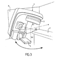
- a conventional radiotherapy treatment apparatus represented for example on the Figure 3 , includes a stand, carrying at one end an irradiation head which ends with a collimator which delimits the beam of radiation (or irradiation beam) and at the other end an imager called portal imager which allows to do digital radiographs of an object placed between the collimator and the imager in general on a treatment table also called patient support.
- the processing apparatus has three axes of rotation, represented on the Figure 3 the horizontal axis of rotation of the stand, allowing the irradiation head to rotate around the treated patient, the axis of rotation of the collimator, which is an axis which passes through the center of the collimator, and which is perpendicular to the horizontal axis of rotation of the stand, this axis coinciding with the vertical axis passing through the center of the collimator when the stand has a zero rotation angle, and the vertical axis of rotation of the patient support, which is an axis that passes by the center of the collimator, when the stand has a zero rotation angle.
- the competition point of these three axes is called the isocenter.
- This isocenter point is materialized in the treatment rooms by five orthogonal laser plies, two frontal, one sagittal and two transverse. These sheets will allow to align three landmarks (one anterior and two lateral) materialized on the skin of the patient (tattoo) or on the surface of a restraint system used to position very accurately the patient, during the preparation phase and treatment planning.
- the two transverse plies are ideally in a vertical plane, orthogonal to the longitudinal direction of the support-patient when it has a zero rotation angle, the two frontal plies are ideally in a horizontal plane, and the sagittal ply is in a vertical plane, orthogonal to the plane of the transverse layers.
- the Winston-Lutz test (W & L) is used to verify the coincidence of the theoretical isocenter and the real isocenter. It consists in aligning a radio-opaque ball, thus of significant electronic density, in particular of the order of that of a metal, spherical (most often steel) on the theoretical isocenter of the apparatus (intersection of the laser layers locating) and to perform multiple x-rays of this object with X-rays from treatment beams.
- the position and "size" of the rotational axis of the stand are determined.
- the position and the "size" of the axis of rotation of the patient support are determined.
- the 0 ° angle for the patient support corresponds to the position of the patient support in which the longitudinal direction of the patient support is aligned with the axis of rotation of the stand, and the angle of 0 ° for the collimator corresponds to a predetermined angle in the collimator.
- size used to define a characteristic of an axis of rotation, as used above for the real axes of rotation, corresponds to the average diameter of the axis of rotation considered, which in the case of the axes of rotation actual rotation, does not exactly match a line, but is contained in a very thin cylinder.
- the image of the radiopaque ball describes a motion whose analysis makes it possible to find the offsets to be produced in order to realign the theoretical isocenter on the real isocenter of the treatment apparatus.
- the radiopaque ball should be small enough that it can be contained in an irradiation beam of small section (about 50 mm) delimited by the collimator. Indeed the movements of the radiopaque ball are not studied with respect to an origin related to the radiation detector, but with respect to the center of the irradiation beam marked on the radiation detector. This makes it possible to overcome any movement of the radiation detector during rotation of the rotating stand, a movement that would be interpreted as a defect on the isocenter of the treatment apparatus. To also limit a possible movement with the rotation of the stand of the beam limiting system contained in the collimator is used beams of small section. There are several test objects to perform the W & L test.
- the most used test object is a radiopaque ball with a diameter of between 2 and 10 mm, which must be aligned on the five laser marking layers. This operation is difficult because, in general, the ball can not carry alignment marks on the laser sheets because of its small size. Even if it was etched, still due to its small size, the alignment of the lasers is controllable only on a reduced surface of the ball, which leads to inaccuracy of placement of the ball of the order of offsets between the real and theoretical isocenters that we want to measure and correct.
- One solution would be to further reduce the size of the ball to specify the alignment of the lasers, but in this case the ball less and less opaque would be difficult to identify in the repeated radiographs.
- test objects are based on the principle of enclosing the ball in a small plastic parallelepiped (20 cm 3 ) comprising a reticle engraved on three of the six faces, the anterior face and the two lateral faces.
- a small plastic parallelepiped (20 cm 3 ) comprising a reticle engraved on three of the six faces, the anterior face and the two lateral faces.
- the parallelepiped geometry prevents the coincidence of the laser layers from being verified and the small dimensions of the enclosing parallelepiped limit the accuracy of the prior checking of the orthogonality and the position in the space (horizontality and verticality) of the laser layers.
- test objects currently used therefore have two major drawbacks: on the one hand, the imprecision of the placement of the radiopaque ball at the intersection of the five laser layers, that is to say on the theoretical isocentre, and secondly, the impossibility of verifying, before or in addition to the W & L test, the orthogonality coincidence, and the position in the space of the laser plies, therefore of the three theoretical axes.
- the US patent US 5281232 describes a test object, consisting of a ball and a sphere surrounding the ball, the diameter of the sphere being smaller than the irradiation beam.
- test object of the invention is defined in claim 1.
- the particular features are contained in the dependent claims.
- the diametrical section of a ball or sphere is defined as the section of this ball or sphere according to one of its diameters.
- the electron density of a material is defined as the number of electrons contained per cubic centimeter. She can express herself with respect to water. It is calculated as the product of: Density of the material (g / cm 3 ) * Avogadro number (6.0228 10 23 atoms / mole) * Z (atomic number of the material) / A (atomic mass of the material).
- This electron density is often expressed relative to that of water (relative electron density).
- the electron density of a material relative mean electron density of the material relative to that of water, or electron density of the material divided by the electron density of water (-3.34 October 23 electrons / cm3)
- the electron density ratios between the electron density material d1 and the electron density material d2 are advantageously between 2 and 20, preferably 12.
- An electron density ratio between the electron density material d1 and the electron density material d2 of 12 gives optimal results for the quality control test.
- the measurements of the position of the image of the electron density ball d1 on the radiation detector are made with respect to the image of the radiation beam on the detector, the position of the ball being detected with respect to the image beam edges on the detector.
- the electronic density of the ball (d1) is higher than the electronic density of the sphere (d2), so that there is an electron density contrast between the ball and the sphere. Since the radio-opacity of a material is an increasing function of the electronic density of this material, the ball (of higher electron density) is more radio-opaque than the sphere (of lower electron density).
- electronic density d2 small relative to the strong electronic density d1 of the ball having a symmetry of rotation, if the section of the radiation beam is smaller than the diameter of the sphere, the rotation of the beam around the sphere will be invisible on the detector, and methods of detecting the edges of the beam and the center of the ball will be strictly the same, regardless of the angle of incidence and beam orientation. Moreover, the diametral section of the sphere of low electron density being greater than the section of the beam, the edges of the beam will be easily spotted on the detector because this location will not be disturbed by the image of the limits of the sphere which will thus be invisible.
- the beam section being greater than the diametral section of the ball, the electronic density ball d1 will be easily located on the detector without disturbing the detection of the edges of the beam.
- the diametral section of the sphere must be greater than the section of the beam, ie the diameter of the sphere must be greater than the diameter of the beam if the beam is of circular section, or the diagonal of the beam if the beam is square section.
- the sphere will have a diameter greater than 20 mm at the beam section.
- the diametral section of the ball must be smaller than the section of the beam, ie the diameter of the ball must be less than the diameter of the beam if the beam is of circular section, or the diagonal of the beam if the beam is square section.
- the ratio between the diametral section of the ball and the section of the beam will be 1/10.
- the electron density material d2 may have an electron density close to that of living human tissues, and in particular a relative electron density (with respect to water) of the order of 1.15.
- the positioning-alignment means being carried by a sphere of electronic density material d2 sufficient diameter on the one hand to carry means that allow an operator to accurately place the test object in the treatment device with the naked eye, and, secondly, to contain in all the weak section of the irradiation beam used for testing.
- the sphere of electronic density material d2 may especially have large dimensions (approximately 500 cm 3 ).
- the locating means may be laser layers projected by laser projectors, for example red or green in color, placed in the treatment room.
- the aligning-positioning means of the sphere in electronic density material d2 carried by the sphere therefore allow precise positioning of the sphere with respect to the marking means constituted by three marking laser plies, since the dimensions of the sphere in electronic density material d2, larger than the dimensions of the ball of electronic density material d1, allow an easy and precise visual placement of the test object with respect to the laser registration layers by the operator performing the test of quality control, this placement being controlled over a greater length (the diameter of the sphere) than for the test objects of the prior art (ball diameter).
- the electronic density material d2 from which the sphere is made may be a plastic material, in particular a plastics material transparent for visible light, especially poly (methyl methacrylate) (PMMA). It is thus possible visually to ensure the correct positioning of the ball of electronic density material d1 in the center of the sphere.
- PMMA poly (methyl methacrylate)
- the electron density material d2 of the sphere allows it to be invisible on the x-ray images taken during the test, only the ball of electron density material d1 in the center being visible on these images.
- the alignment-positioning means of the sphere consist of three equatorial lines, orthogonal two-by-two, formed on the surface of the sphere of electronic density material d2, said lines may be materialized by a painted or printed line, or by an engraved groove.
- the visible lines thus make it possible to verify visually, during the placement of the test object, the orthogonality, the position in the space (horizontality and verticality) and the coincidence of the laser plies, which must align with the visible lines of the object.
- the alignment-positioning means of the sphere may further comprise, on either side of each equatorial line, additional visible lines, advantageously discontinuous, parallel to the three equatorial lines, said additional visible lines being materialized by a painted or printed line, or by an etched groove and said additional visible lines being formed at a predetermined spacing from the associated equatorial line, such that an alignment of the locating means on said additional visible lines provides an indication visual position of the ball in electronic density material d1 relative to the point of concurrence of the three axes (V ', H', C ').
- the operator can deduce, when they are aligned with the registering means, the position of the ball of electronic density material d1, and therefore the correction to make the placement of the test object without any other measuring device.
- the visible lines and, where appropriate, the additional visible lines may be covered with a substance capable of reflecting light in the visible spectrum, to illuminate the same color as the color of the laser sheets, when said visible lines, and when present, said additional visible lines, are aligned with the laser sheets.
- the visible lines may for example advantageously be light or white. Thus, it is facilitated for the operator visual confirmation of the alignment of visible lines and tracking means, by reflection of light.
- the visible lines and, where appropriate, the additional visible lines may be practiced in strip-shaped equatorial zones of the sphere surface, which have been processed to absorb or scatter light in the visible spectrum.
- the visual confirmation of the alignment of the visible lines is then accentuated, possibly additional visible lines with the marking means, since the light of the locating means is reflected on the lines. visible, and absorbed or scattered outside these visible lines.
- the strip-like areas may be formed by roughing or dark-colored painting.
- the dark color may for example be black.
- the marking means are laser plies and the visible lines are light in color
- the visible lines reflect the laser light when aligned with the laser plies, whereas in the frosted strip-like areas or dark color the laser light is scattered or absorbed.
- the diameter of the sphere may be chosen so large that the visual alignment-positioning means can be easily distinguished by the human eye, the diameter of said sphere being understood in particular. between 80 and 200 mm, the visible lines and, where appropriate, the additional visible lines having a width of between 0.1 mm and 0.5 mm, in particular of 0.2 mm (width of painted line or groove), and additional visible lines, when present, being spaced 1 mm apart on each side of each equatorial visible line, and the strip-like areas, when present, having a width of between 2 mm and 10 mm mm, in particular 5 mm, the ball having in particular a diameter of between 2 and 10 mm, preferably between 5 and 6 mm.
- the laser plies when the laser plies are outside the visible lines, the laser plies diffuse into the frosted band area or are absorbed into the dark-colored band area.
- the laser plies With a band-shaped area 5 mm wide, and lines equatorial visible and additional visible lines of width 0.2 mm, it is possible, with a spacing of 1 mm between each visible line, to place in each zone in the form of a band an equatorial visible line, and two additional visible lines of part and of another of each equatorial visible line.
- the laser plies no longer diffuse or are no longer absorbed in the strip-like zones and this visible line is illuminated.
- the white color is chosen preferably for visible lines to make this system as efficient with green laser layers and with red laser layers.
- roughening or darkening a 5mm strip-shaped area prevents laser sheets on one side from entering the transparent sphere, diffracting, and disrupting alignment of a laser sheet on the other side of the sphere (contralateral laser layer).
- the ball of electronic density material d1 may be tungsten.
- the placing means may be constituted by an elongated metal element, of rod or tube type, for example titanium or aluminum, one end of which is intended for be introduced into a hole made in the sphere and to be secured for example by screwing, and by a plate which is fixed on the other end of the elongate element and which is arranged to serve as a counterweight to the object -test and the elongated element when the plate is placed on the upper plane of the patient support and to be able, from there, to be oriented for the placement of the test object at the point of competition of the three axes (V ', H ', C').
- the plate may comprise means for adjusting the level of said plate relative to the plane of the patient support during placement of the test object. These means may in particular be leveling screws.
- the plate has a thickness of between 20 and 40 mm, preferably 20 mm, a width of between 50 and 200 mm, preferably 80 mm, and a length of between 200 and 500 mm, preferably 300 mm
- the elongated element has a length of between 50 and 300 mm, preferably 100 mm
- the elongated element can be introduced into the plate over a length of between 20 and 80 mm, preferably 50 mm.
- the elongated element is a rod
- its diameter is between 5 and 15 mm, and is preferably 10 mm maximum.
- the sphere may comprise a radial channel of diameter slightly greater than that of the ball, said channel being closed by a rod of electronic density material d2 that can project from the surface of the ball.
- sphere, and the elongate member may be adapted to be connected to the sphere by screwing at the periphery of the rod, the latter may comprise an axial recess of complementary shape to the shape of the rod when the latter is projecting, for receive this salient part.
- the protruding rod serves in this case to strengthen the maintenance of the sphere on the elongated element. It has a diameter of between 2 and 10 mm, preferably 8 mm, and a length of between 60 and 120 mm, preferably 70 mm.
- the elongate metal element can be secured to the sphere at the intersection of two equatorial visible lines.
- the elongated element may be a solid rod, in which case the rod of electronic density material d2 does not protrude from the sphere, the elongated element then only secured to the sphere by screwing.
- the elongate member may also be a hollow tube, to lighten the weight of the test-object-rod assembly.
- the elongate member has an axial recess interengaging with the projecting portion of the electron density material shaft d2 enhances the retention of the sphere on the elongate member and may advantageously serve as a guide for the forming operation.
- the sagittal web is vertical and in the longitudinal direction of the patient support, the two transverse webs are in the same plane, orthogonal to the plane of the sagittal and vertical ply, and the frontal plies are in the same plane
- the present invention also relates to a radiotherapy apparatus equipped with the test object as defined above.
- the Figure 3 represents a conventional radiotherapy treatment apparatus, in a radiotherapy treatment room.
- This apparatus comprises, in a conventional manner, a structure which comprises at least one vertical wall P carrying a stand 1, and a table or patient support 2.
- the stand 1 On this vertical wall P is mounted in a conventional manner mobile in rotation about a horizontal axis 1, substantially C-shaped stand seen in profile.
- the stand 1 carries at one end an irradiation head which ends with a collimator 3, and at the other end, facing the collimator 3 and turned towards it, a radiation detecting device 4 emitted from the collimator 3, this radiation detection device being called portal imager 4, which makes it possible to take snapshots of the radiation emitted from the collimator 3, and to perform the computer processing of the images.
- the stand 1 is rotatable 360 ° about a horizontal axis H, as shown in FIG. Figure 3 , the horizontal axis H passing substantially through the middle of the portion in the vertical plane of the stand 1.
- the zero rotation angle of the stand 1 corresponds to the vertical position of the stand 1, as shown in FIG. Figure 4 .
- the collimator 3 in a conventional manner for the radiotherapy treatment apparatus, has an axis of rotation C around itself, said axis of rotation passing through the center of the collimator 3, and having the direction of the radiation emitted from the collimator 3.
- the patient table or support 2 also has a vertical axis of rotation V, passing through the center of the collimator 3 when the stand 1 has a zero rotation angle, and makes it possible to move the patient relative to the stand to radiate the patient over different regions.
- the zero angle of rotation of the patient support 2 corresponds to the position of the patient support 2 in which the horizontal rotation axis H of the stand 1 is parallel to the longitudinal direction of the patient support 2.
- the stand 1 has a zero rotation angle, as for example this is represented on the Figure 4 ideally, the axis of rotation C of the collimator 3 and the axis of rotation V of the patient support 2 coincide.
- intersection of the three axes of rotation H, V, C constitutes the real isocenter G of the radiotherapy treatment apparatus.
- laser projectors 5, 6 are provided, on the one hand on a wall P ', orthogonal to the wall P carrying the stand 1, and on the other hand on the wall opposite the wall P, for projecting laser sheets, represented hatched on the Figure 4 .
- a laser projector identical to the laser projector 5 carried by the wall P ' is carried on the wall opposite the wall P ', the two laser projectors being located face to face and projecting in the same planes laser plies towards the test object, these planes being defined below in relation to the laser projector 5.
- These laser sheets serve to position the theoretical isocenter G 'of the radiotherapy treatment apparatus.
- the first laser ply has a horizontal plane and is called the frontal ply
- the second laser ply called the transverse ply
- the laser projector 6, shown schematically on the Figure 4 is placed on the wall (not shown to facilitate the reading of the drawing) opposite the wall P, and projects a vertical laser ply, called sagittal ply, whose plane is perpendicular to the respective planes of the first and second ply, and which constitutes the median plane in the longitudinal direction of the patient support 2, when the patient support 2 has a zero rotation angle, as shown in FIG. Figure 4 .
- intersection of the sagittal and frontal plies defines the theoretical axis of rotation H 'of the stand 1, while the intersection of the sagittal and transverse plies defines the theoretical axes of rotation of the collimator 3 C' and the patient support 2 V '. when the stand 1 has a zero rotation angle.
- This theoretical isocenter G ' serves to represent, for the operator, the position of the center of the tumor to be treated on the patient.
- the two isocenters G and G 'must correspond, as indicated above.
- the real isocenter G fixed by the mechanical characteristics of the treatment apparatus, can not be moved by the operator.
- the theoretical isocenter G ' is therefore adjusted by adjusting the laser layers to correspond to the real isocentre G.
- the position of the theoretical isocenter G ' is corrected by adjusting the laser plies, until the position of the theoretical isocenter G' corresponds to the position of the real isocenter G.
- test object of the present invention used to carry out this test is represented on the Figures 1, 2 and 5 .
- d2 corresponding to a relative electron density of 1.156
- PMMA poly (methyl methacrylate)
- this sphere 8 In the center of this sphere 8 is embedded a spherical ball 9 of electronic density material d1, such as tungsten, the ball 9 having a diameter of 5 mm, the electron density d1 of tungsten corresponding to a relative electron density of 13.995.
- electronic density material d1 such as tungsten
- a rod 8b of the same electron density material d2 as the sphere 8 protrudes from the sphere 8 from the center thereof, the rod 8b having the direction of a radius of the sphere 8.
- Three strip-like zones 10, 11, 12, called bottom strips, are formed on the surface of the sphere 8.
- the three bottom strips 10, 11, 12 are orthogonal equatorial strips in pairs, each bottom strip 10, 11, 12 being formed by roughening the surface of the sphere or painting the surface of the sphere with a dark color on an equatorial peripheral band of width 5 mm.
- the bottom strips 10, 11, 12 absorb or scatter light in the visible spectrum.
- the sphere 8 comprises three sets of equatorial visible lines 10a, 11a, 12a, the visible lines being materialized in this embodiment by grooves, the sets being orthogonal pairs, and etched on the surface of the sphere 8, in the center each band of respective bottom 10, 11, 12, each set of grooves 10a, 11a, 12a having the same direction as the respective bottom strip 10, 11, 12 in which it is formed.
- Each set of grooves 10a, 11a, 12a comprises a continuous equatorial groove, traversing the entire circumference of the sphere 8, as well as several auxiliary grooves, parallel to the equatorial groove, and located symmetrically on either side of the Equatorial groove, with a spacing of 1 mm between each groove.
- each set of grooves 10a, 11a, 12a are covered with a white material, for example a paint, reflecting the light in the visible spectrum, and width of 0.2 mm.
- a white material for example a paint, reflecting the light in the visible spectrum, and width of 0.2 mm.
- Each set of grooves 10a, 11a, 12a comprises a central equatorial groove and two auxiliary grooves on either side of the equatorial groove, the grooves in each bottom strip being spaced apart by 1 mm.
- the bottom strips 10, 11, 12 and the sets of grooves 10a, 11a, 12a are arranged in such a way that the projecting portion of the rod 8b is at the intersection of two equatorial grooves, and therefore at the intersection of two bottom strips 10, 11, 12.
- an elongated rod-type element 13 of metal such as titanium or aluminum, carries at one end a male thread 13a, said rod 13 having at this end an axial recess of complementary shape to the projecting portion of the stem 8b.
- the rod 13 is engaged in the projecting portion of the rod 8b and screwed by screwing to a thread 8a carried by the sphere 8 adjacent its surface, at the base of the projecting portion of the rod 8b.
- a support 14 consisting of a rectangular plate made of dense plastic (polyoxymethylene type sold under the trademark DELRIN ® ) with rounded edges, 20 mm thick, bears on one of its thickness sides a bore 15, to the inside which the other end of the rod 13 is fixed.
- dense plastic polyoxymethylene type sold under the trademark DELRIN ®
- a through hole 16 is made through the thickness dimension of the support 14, at the inner end of the bore 15, the hole 16 allowing the transverse passage of a metal shaft, in order to lock the rod in position. 13 and to avoid any rotational movement relative to the support 14 of the rod 13, and therefore of the sphere 8.
- the support 14 further comprises leveling screws 18, making it possible to adjust the height and the inclination of the support 14 with respect to the upper surface of the patient support 2 on which it is placed as part of the Winston test. Lutz.
- a first equatorial groove is in the middle plane of the support, so horizontal, a second equatorial groove is vertical, in the axis of the rod 13, the third equatorial groove being orthogonal to the other two, vertical.
- the test object constituted by the sphere 8 is fixed by screwing the threads 8a of the sphere 8 and 13a of the rod 13, the rod 13 being itself fixed to the support 14 , so that at least one of the equatorial grooves of one of the groove sets 10a, 11a, 12a belongs to the middle plane of the support 14, as shown in FIG. Figure 1 .
- the support 14 is placed at the end of the patient support 2 turned towards the stand 1, so that only the support 14 rests on the upper surface of the patient support 2, the stem 13 and the sphere 8 being in -faux above the portal imager 4.
- the laser projectors 5 and 6 (as well as the laser projector not shown in front of the laser projector 5) are then activated, so as to project the sagittal laser plies, frontal and transverse.
- the position of the sphere 8 is adjusted so that each equatorial groove of each groove clearance 10a, 11a, 12a is aligned with one of the five laser plies. If the laser plies are not rigorously orthogonal two by two, which is observed if we can not place the sphere 8 simultaneously on the five plies so that each equatorial groove of each set of grooves 10a, 11a, 12a corresponds to to a respective laser ply, it is then necessary to adjust the projectors 5, 6 to ensure that this orthogonality of the five laser plies is respected.
- the laser layers are not aligned with one of the white grooves of each set of grooves 10a, 11a, 12a etched on the surface of the sphere 8 in the bottom strips 10, 11, 12, the lasers scatter or are absorbed into the respective backing strip 10, 11, 12. If, on the other hand, the laser layers are aligned with one of the white grooves, then the lasers no longer diffuse or are no longer absorbed by the bottom strip 10, 11, 12, but are reflected by the white groove, and the white groove takes the color of the laser sheet, red or green in the case of most lasers used.
- the method of manufacturing the test object is as follows: a PMMA sphere 8 with a diameter of 100 mm is taken and a cylindrical channel is drilled with a 5 mm diameter end-to-end cutter from a point (pole) to the surface of the sphere 8, along a radius thereof, by digging the sphere 8 beyond the center of the latter by 2.5 mm.
- a larger internal thread diameter portion is then formed in the vicinity of the surface of the sphere 8, at the base of the projecting portion of the rod 8b, the rod 8b protruding from the sphere 8 by about 40 mm.
- the interlocking of the rod 8b in the recess of the rod 13 reinforces the maintenance of the sphere on the rod 13, and can serve as a guide for the operation of forming the thread 8a on the sphere.
- the other end of the rod (13) is then attached to a plate (14), and the strip-like zones (10, 11, 12) are optionally formed by either roughing with a 3D machine tool or a paint of dark color, for example of black color, capable of diffusing or absorbing wavelengths in the visible spectrum, advantageously such that the rod (13) is placed in the center of the overlap region between two zones in the form of band (10, 11, 12).
- the visible lines and, where appropriate, the additional visible lines (10a, 11a, 12a) are then formed by etching or printing on the surface of the sphere (8) with a 3D machine tool, advantageously so that the rod (13) is placed at the point of competition of two equatorial visible lines, and optionally, the visible lines and, where appropriate, the additional visible lines (10a, 11a, 12a) are colored by painting them by hand with a brush, for example with a white or light color, reflecting the wavelengths in the visible spectrum.
Claims (16)
- Testobjekt für einen Test zur Qualitätskontrolle eines Geräts zur Strahlentherapie-Behandlung, das ein rundes Kügelchen (9) umfasst, das aus einem Material hergestellt ist, das eine Elektronendichte d1 aufweist, wobei das runde Kügelchen (9) mit der Elektronendichte d1 in der Mitte einer Kugel (8) aus einem Material mit einer Elektronendichte d2 angeordnet ist, um mit ihr das Testobjekt zu bilden, wobei das Verhältnis der Elektronendichte d1 zur Elektronendichte d2 größer oder gleich 1,1 beträgt, wobei die Kugel (8) Mittel (8a) aufweist, die ermöglichen, sie fest mit Mitteln (13, 14) zum Platzieren des Testobjekts an dem Gerät zur Strahlentherapie-Behandlung zu verbinden, wobei das Kügelchen einen Durchmesser zwischen 2 und 10 mm, vorzugsweise zwischen 5 und 6 mm aufweist, dadurch gekennzeichnet, dass der Durchmesser der Kugel (8) zwischen 80 und 200 mm liegt, und die Kugel (8) auf ihrer Außenfläche Mittel (10a, 11a, 12a) zum optischen Ausrichten trägt, die aus drei sichtbaren, paarweise orthogonalen Äquatoriallinien gebildet sind, die auf der Oberfläche der Kugel (8) ausgebildet sind und eine Positionierung des Testobjekts ermöglichen.
- Testobjekt nach Anspruch 1, dadurch gekennzeichnet, dass das Material mit der Elektronendichte d2, aus dem die Kugel (8) hergestellt ist, ein Kunststoff ist, insbesondere ein Kunststoff, der für sichtbares Licht durchlässig ist, insbesondere aus Polymethylmethacrylat (PMMA).
- Testobjekt nach einem der Ansprüche 1 oder 2, dadurch gekennzeichnet, dass die Ausrichtungs- und Positionierungsmittel (10a, 11a, 12a), die auf der Oberfläche der Kugel (8) aus dem Material mit der Elektronendichte d2 ausgebildet sind, durch einen aufgezeichneten oder aufgedruckten Strich oder durch eine eingeritzte Rille realisiert sind.
- Testobjekt nach Anspruch 3, dadurch gekennzeichnet, dass die Ausrichtungs- und Positionierungsmittel (10a, 11a, 12a) der Kugel (8) ferner auf beiden Seiten jeder Äquatoriallinie zusätzliche sichtbare, vorteilhafterweise unterbrochene Linien parallel zu den drei Äquatoriallinien aufweisen, wobei die zusätzlichen sichtbaren Linien durch einen aufgezeichneten oder aufgedruckten Strich oder durch eine eingeritzte Rille realisiert sind und die zusätzlichen sichtbaren Linien in einem festgelegten Abstand zur zugehörigen Äquatoriallinie ausgebildet sind.
- Testobjekt nach einem der Ansprüche 3 oder 4, dadurch gekennzeichnet, dass die sichtbaren Linien und gegebenenfalls die zusätzlichen sichtbaren Linien mit einer Substanz überzogen sind, die in der Lage ist, Licht im sichtbaren Spektrum zu reflektieren.
- Testobjekt nach einem der Ansprüche 3 bis 5, dadurch gekennzeichnet, dass die sichtbaren Linien und gegebenenfalls die zusätzlichen sichtbaren Linien in streifenförmigen Äquatorialbereichen der Kugeloberfläche vorgesehen sind, die behandelt wurden, um Licht im sichtbaren Spektrum zu absorbieren oder zu streuen.
- Testobjekt nach Anspruch 6, dadurch gekennzeichnet, dass die streifenförmigen Bereiche (10, 11, 12) durch Mattieren oder Aufbringen einer dunklen Farbe gebildet wurden.
- Testobjekt nach einem der Ansprüche 4 bis 7, dadurch gekennzeichnet, dass die sichtbaren Linien und gegebenenfalls die zusätzlichen sichtbaren Linien eine Breite zwischen 0,1 mm und 0,5 mm, insbesondere von 0,2 mm aufweisen, und die zusätzlichen sichtbaren Linien, wenn sie vorhanden sind, auf beiden Seiten jeder sichtbaren Äquatoriallinie einen Abstand von 1 mm aufweisen, und die streifenförmigen Bereiche, wenn sie vorhanden sind, eine Breite zwischen 2 mm und 10 mm, insbesondere von 5 mm aufweisen.
- Testobjekt nach einem der Ansprüche 1 bis 8, dadurch gekennzeichnet, dass das Material mit der Elektronendichte d1, das das Kügelchen (9) bildet, Wolfram ist.
- Testobjekt nach einem der Ansprüche 1 bis 9, dadurch gekennzeichnet, dass die Platzierungsmittel (13, 14) aus einem länglichen Metallelement (13) in der Art eines Stabs oder einer Röhre, beispielsweise aus Titan oder aus Aluminium, gebildet sind, wovon ein Ende dafür bestimmt ist, in eine Bohrung (8a) gesteckt zu werden, die in die Kugel (8) eingebracht ist, und dort beispielsweise durch Verschrauben fest verbunden zu werden, und aus einer Platte (14), die an dem anderen Ende des länglichen Elements (13) befestigt ist und angeordnet ist, um als Gegengewicht zu dem Testobjekt und dem länglichen Element (13) zu dienen, wenn die Platte (14) bezogen auf das Gerät zur Strahlentherapie-Behandlung angeordnet ist.
- Testobjekt nach Anspruch 10, dadurch gekennzeichnet, dass die Platte (14) Mittel (18) zum Einstellen der Höhe der Platte (14) bezogen auf die Ebene einer Patientenliege (2) des Geräts zur Strahlentherapie-Behandlung beim Platzieren des Testobjekts aufweist.
- Testobjekt nach einem der Ansprüche 10 oder 11, dadurch gekennzeichnet, dass die Kugel (8) einen radialen Kanal mit einem Durchmesser etwas größer als der des Kügelchens (9) aufweist, wobei der Kanal mit einem Stab (8b) aus einem Material mit der Elektronendichte d2 verschlossen ist, der aus der Oberfläche der Kugel (8) herausragen kann, und dadurch, dass das längliche Element (13) in der Lage ist, mit der Kugel durch Aufschrauben am Umfang des Stabs (8b) verbunden zu werden, wobei dieses eine axiale Aussparung aufweisen kann, deren Form auf die Form des Stabs (8b) abgestimmt ist, wenn dieser herausragt, um diesen herausragenden Teil aufzunehmen.
- Testobjekt nach einem der Ansprüche 10 bis 12, dadurch gekennzeichnet, dass das längliche Element (13) mit der Kugel (8) an dem Schnittpunkt von zwei sichtbaren Äquatoriallinien (10a, 11a, 12a) fest verbunden ist.
- Verfahren zur Herstellung eines Testobjekts nach einem der Ansprüche 1 bis 13, dadurch gekennzeichnet, dass es folgende Schritte umfasst:- Verwenden einer Kugel (8) aus einem Material mit der Elektronendichte d2 und Einbringen, mit einem Radiusfräser mit demselben Durchmesser wie dem des runden Kügelchens (9) aus einem Material mit der Elektronendichte d1, eines zylindrischen Kanals von einer Stelle an der Oberfläche der Kugel (8) aus, entlang einem Radius derselben, durch Aushöhlen der Kugel (8) über die Mitte derselben hinaus über einen Abstand, der der Hälfte des Durchmessers des Kügelchen (9) aus dem Material mit der Elektronendichte d1 entspricht;- Einbringen des Kügelchens (9) bis ganz unten in diesen Kanal;- Verschließen der verbleibenden Bohrung mit einem Stab (8b) aus einem Material mit der Elektronendichte d2 mit demselben Durchmesser wie dem des Kügelchens (9), an dessen Ende die umgekehrte Form des Halbkügelchens (9) eingebracht wurde, wobei der Stab (8b) dann mit einem Klebstoff mit der Elektronendichte d2 in den Kanal geklebt wird und der Stab (8b) aus der Oberfläche der Kugel (8) ragen kann;- Bilden eines Teils mit einem größeren Durchmesser mit Innengewinde in der Nähe der Oberfläche der Kugel (8), am Fuß des herausragenden Teils des Stabs (8b), wenn dieser herausragt;- Schrauben eines länglichen Elements (13), das an einem Ende ein Außengewinde (13a) aufweist, auf das Gewinde (8a) der Kugel (8), wobei das längliche Element (13) wahlweise eine axiale Aussparung für die Aufnahme des herausragenden Teils des Stabs (8b) aufweist, wenn dieser herausragt;- Befestigen des anderen Endes des länglichen Elements (13) an einer Platte (14);- wahlweise Bilden der streifenförmigen Äquatorialbereiche (10, 11, 12) entweder durch Mattieren mit einer 3D-Werkzeugmaschine oder durch Auftragen einer dunklen Farbe, die in der Lage ist, Wellenlängen im sichtbaren Spektrum zu streuen oder zu absorbieren, vorteilhafterweise derart, dass das längliche Element (13) mit der Kugel in der Mitte des Überdeckungsbereichs zwischen zwei streifenförmigen Äquatorialbereichen (10, 11, 12) fest verbunden wird;- Bilden der sichtbaren Linien und gegebenenfalls der zusätzlichen sichtbaren Linien (10a, 11a, 12a) durch Einritzen in oder Aufdrucken auf die Oberfläche der Kugel (8) mit einer 3D-Werkzeugmaschine, vorteilhafterweise derart, dass das längliche Element (13) mit der Kugel am Punkt des Zusammentreffens von zwei sichtbaren Äquatoriallinien fest verbunden wird; und- wahlweise Färben der sichtbaren Linien und gegebenenfalls der zusätzlichen sichtbaren Linien (10a, 11a, 12a) durch Bemalen derselben per Hand mit einem Pinsel.
- Verfahren zum Überprüfen der Übereinstimmung, Orthogonalität und räumlichen Lage in einem Behandlungsraum von Markierungsmitteln (5, 6) des Isozentrums eines Geräts zur Strahlentherapie-Behandlung, wobei das Isozentrum der Schnittpunkt der drei theoretischen Drehachsen (V', H', C') des Geräts zur Strahlentherapie-Behandlung ist, dadurch gekennzeichnet, dass es folgende Vorgänge umfasst:- Anschalten der Markierungsmittel (5, 6) der drei theoretischen Achsen (V', H', C'), um die drei theoretischen Achsen (V', H', C') optisch darzustellen;- Platzieren eines Testobjekts nach einem der Ansprüche 1 bis 13 an dem beobachteten Punkt des Zusammentreffens oder Isozentrum (G') der drei theoretischen Achsen (V', H', C');- optisch Feststellen, ob jedes der Markierungsmittel (5, 6) der drei theoretischen Achsen (V', H', C') den jeweiligen entsprechenden Ausrichtungs- und Positionierungsmitteln (10a, 11a, 12a) an dem Testobjekt folgt;- in Abhängigkeit von dem oder den beobachteten Unterschied(en) Ändern der Einstellung der Markierungsmittel (5, 6), damit die Markierungsmittel (5, 6) der theoretischen Achsen (V', H', C') den jeweiligen entsprechenden Ausrichtungs- und Positionierungsmitteln (10a, 11a, 12a) an dem Testobjekt folgen, um die Übereinstimmung, Orthogonalität und räumliche Lage der Markierungsmittel (5, 6) der drei theoretischen Achsen (V', H', C') zu gewährleisten.
- Verfahren zum Suchen nach dem Isozentrum eines Geräts zur Strahlentherapie-Behandlung unter Verwendung eines Testobjekts nach einem der Ansprüche 1 bis 13, wobei äußere Mittel und/oder Mittel, die das Gerät trägt, für die optische Darstellung der drei theoretischen Drehachsen (V', H', C') des Geräts und ihres Schnittpunkts oder Isozentrums vorgesehen sind, wobei das Verfahren dadurch gekennzeichnet ist, dass es folgende Vorgänge umfasst:- Überprüfen der Übereinstimmung, Orthogonalität und räumlichen Lage von Markierungsmitteln (5, 6) der drei theoretischen Achsen (V', H', C') gemäß dem Verfahren nach Anspruch 15;- während das Testobjekt im theoretischen Isozentrum (G') bleibt, Bestrahlen des Testobjekts mit einem Strahlenbündel, das von dem Kollimator (3) ausgesendet wird, wobei das Bündel von den Strahlennachweismitteln (4) des Behandlungsgeräts erfasst wird und die Bestrahlung in unterschiedlichen Positionen der Patientenliege (2), des Stativs (1) und des Kollimators (3) um jede ihrer Drehachsen (V, H, C) erfolgt;- Analysieren der erhaltenen Bilder;- Bestimmen der tatsächlichen Position der drei Drehachsen (V, H, C) und ihres Punkts des Zusammentreffens (G), dem tatsächlichen Isozentrum des Geräts zur Strahlentherapie-Behandlung;- Einstellen der Markierungsmittel (5, 6) der drei theoretischen Achsen (V', H', C'), damit das tatsächliche (G) und theoretische (G') Isozentrum übereinstimmen.
Priority Applications (2)
| Application Number | Priority Date | Filing Date | Title |
|---|---|---|---|
| EP20100189893 EP2450083B1 (de) | 2010-11-03 | 2010-11-03 | Testobjekt für die Qualitätskontrolle eines Geräts zur Strahlentherapie-Behandlung, sowie Herstellungs- und Anwendungsverfahren dieses Testobjekts |
| ES10189893T ES2431945T3 (es) | 2010-11-03 | 2010-11-03 | Objeto de prueba para el control de calidad de un aparato de tratamiento por radioterapia y procedimientos de fabricación y de utilización de dicho objeto de prueba |
Applications Claiming Priority (1)
| Application Number | Priority Date | Filing Date | Title |
|---|---|---|---|
| EP20100189893 EP2450083B1 (de) | 2010-11-03 | 2010-11-03 | Testobjekt für die Qualitätskontrolle eines Geräts zur Strahlentherapie-Behandlung, sowie Herstellungs- und Anwendungsverfahren dieses Testobjekts |
Publications (2)
| Publication Number | Publication Date |
|---|---|
| EP2450083A1 EP2450083A1 (de) | 2012-05-09 |
| EP2450083B1 true EP2450083B1 (de) | 2013-08-07 |
Family
ID=43447119
Family Applications (1)
| Application Number | Title | Priority Date | Filing Date |
|---|---|---|---|
| EP20100189893 Active EP2450083B1 (de) | 2010-11-03 | 2010-11-03 | Testobjekt für die Qualitätskontrolle eines Geräts zur Strahlentherapie-Behandlung, sowie Herstellungs- und Anwendungsverfahren dieses Testobjekts |
Country Status (2)
| Country | Link |
|---|---|
| EP (1) | EP2450083B1 (de) |
| ES (1) | ES2431945T3 (de) |
Cited By (1)
| Publication number | Priority date | Publication date | Assignee | Title |
|---|---|---|---|---|
| GB2607702A (en) * | 2021-04-19 | 2022-12-14 | Aktina Corp | X-ray transmission image analysis for the evaluation of LINAC isocenter quality |
Families Citing this family (2)
| Publication number | Priority date | Publication date | Assignee | Title |
|---|---|---|---|---|
| CN103070697B (zh) * | 2012-12-31 | 2014-12-24 | 沈阳东软医疗系统有限公司 | Pet系统探测装置的符合判断电路及其调整装置和方法 |
| EP3421086B1 (de) | 2017-06-28 | 2020-01-15 | OptiNav Sp. z o.o. | Bestimmung von geometrischen informationen über eine medizinische behandlungsanordnung mit drehbarer behandlungsstrahlungsquelleneinheit |
Family Cites Families (5)
| Publication number | Priority date | Publication date | Assignee | Title |
|---|---|---|---|---|
| US5281232A (en) * | 1992-10-13 | 1994-01-25 | Board Of Regents Of The University Of Arizona/ University Of Arizona | Reference frame for stereotactic radiosurgery using skeletal fixation |
| DE19907065A1 (de) * | 1999-02-19 | 2000-08-31 | Schwerionenforsch Gmbh | Verfahren zur Überprüfung eines Isozentrums und einer Patientenpositionierungseinrichtung eines Ionenstrahl-Therapiesystems |
| WO2006007584A2 (en) * | 2004-07-01 | 2006-01-19 | East Carolina University | Radiation isocenter measurement devices and methods and 3-d radiation isocenter visualization systems and related methods |
| KR100808110B1 (ko) * | 2006-07-11 | 2008-03-04 | 가톨릭대학교 산학협력단 | 방사선량계 특성분석용 홀더장치 |
| FR2945955B1 (fr) * | 2009-06-02 | 2012-03-23 | Qualiformed Sarl | Objet-test pour le controle qualite d'un appareil de traitement par radiotherapie et procedes de fabrication et d'utilisation dudit objet-test. |
-
2010
- 2010-11-03 EP EP20100189893 patent/EP2450083B1/de active Active
- 2010-11-03 ES ES10189893T patent/ES2431945T3/es active Active
Cited By (1)
| Publication number | Priority date | Publication date | Assignee | Title |
|---|---|---|---|---|
| GB2607702A (en) * | 2021-04-19 | 2022-12-14 | Aktina Corp | X-ray transmission image analysis for the evaluation of LINAC isocenter quality |
Also Published As
| Publication number | Publication date |
|---|---|
| ES2431945T3 (es) | 2013-11-28 |
| EP2450083A1 (de) | 2012-05-09 |
Similar Documents
| Publication | Publication Date | Title |
|---|---|---|
| CA2705556C (fr) | Objet-test pour le controle qualite d'un appareil de traitement par radiotherapie et procedes de fabrication et d'utilisation dudit objet-test | |
| BE1013614A3 (fr) | Appareil de determination de la distribution dans l'eau d'une dose de type fantome. | |
| TW200815748A (en) | Control of X-ray beam spot size | |
| EP2450083B1 (de) | Testobjekt für die Qualitätskontrolle eines Geräts zur Strahlentherapie-Behandlung, sowie Herstellungs- und Anwendungsverfahren dieses Testobjekts | |
| JP7319055B2 (ja) | 患者プランニング及び治療システム用の多目的オブジェクト | |
| FR2703237A1 (fr) | Mammographe équipé d'un dispositif de prises en vues stéréotaxiques à détecteur numérique et procédé d'utilisation d'un tel mammographe . | |
| EP2952227A1 (de) | Testobjekt zur korrektur von störenden bewegungen eines ausgabe-bildgebungssystems, das in einem gerät zur externen strahlentherapiebehandlung zum einsatz kommt, wenn dieses sich bewegt | |
| WO2016071645A1 (fr) | Système d'imagerie radiographique et procédé de positionnement d'un tel système | |
| EP3368919B1 (de) | Dreh-kollimator zur bestimmung der lage eines mit detektoren ausgestatteten elementes in einem röntgen abbildungssystem | |
| FR2717587A1 (fr) | Dispositif de localisation en temps réel de sources de rayonnement. | |
| EP2363169B1 (de) | Testobjekt und Verfahren zur Verwendung dieses Testobjekts, das die Kontrolle des Zusammenfalls der Lichtfelder und der bestrahlten Felder auf einem Strahlentherapiegerät ermöglicht | |
| FR2678385A1 (fr) | Procede et dispositif de controle par ultrasons de l'etat de surface d'un alesage, notamment de l'alesage d'un essieu-axe de chemin de fer. | |
| FR2530857A1 (fr) | Systeme de filtre pour appareil de radiographie | |
| CN100346134C (zh) | 测量薄层厚度的设备 | |
| EP4010739B1 (de) | Rotierender kollimator für ein röntgendetektionssystem | |
| FR2782385A1 (fr) | Determination de la tache de mesure dans l'analyse par fluorescence x | |
| FR2831958A1 (fr) | Dispositif de plateau tournant destine a supporter et orienter une charge | |
| EP3517940B1 (de) | Verfahren und system zur bestimmung der variation der streuintensität eines zweidimensionalen gitters entlang einer bestimmten richtung | |
| CH649408A5 (fr) | Appareil de mesure, notamment d'epaisseurs de couches minces, avec mise en coincidence de l'axe d'une sonde de mesure avec une normale a la surface d'une piece a controler. | |
| FR3097656A1 (fr) | Camera Compton et procédé d’imagerie 3D COMPTON | |
| EP1195575A1 (de) | Verfahren und Vorrichtung zur Determinierung von Oberflächenkoordinaten und ihre Anwendung sowie Montierungsverfahren für einen Laseremitter-Detektor | |
| FR2723212A1 (fr) | Installation de dosimetrie de grande maniabilite pour la caracterisation des faisceaux de rayonnements ionisants | |
| EP3679404A1 (de) | Vorrichtung zur optischen messung von strahlungsdosen, die von einem geldosimeter mittels polarisiertem licht absorbiert werden | |
| CN108051456A (zh) | X-ct系统用测量夹具 | |
| CN111487261A (zh) | 一种基于19.6nm软X射线的准单能背光阴影成像方法 |
Legal Events
| Date | Code | Title | Description |
|---|---|---|---|
| PUAI | Public reference made under article 153(3) epc to a published international application that has entered the european phase |
Free format text: ORIGINAL CODE: 0009012 |
|
| AK | Designated contracting states |
Kind code of ref document: A1 Designated state(s): AL AT BE BG CH CY CZ DE DK EE ES FI FR GB GR HR HU IE IS IT LI LT LU LV MC MK MT NL NO PL PT RO RS SE SI SK SM TR |
|
| AX | Request for extension of the european patent |
Extension state: BA ME |
|
| 17P | Request for examination filed |
Effective date: 20121108 |
|
| GRAP | Despatch of communication of intention to grant a patent |
Free format text: ORIGINAL CODE: EPIDOSNIGR1 |
|
| RIC1 | Information provided on ipc code assigned before grant |
Ipc: A61B 6/00 20060101ALN20130131BHEP Ipc: A61B 6/08 20060101ALN20130131BHEP Ipc: A61N 5/10 20060101AFI20130131BHEP |
|
| RIC1 | Information provided on ipc code assigned before grant |
Ipc: A61B 6/00 20060101ALN20130201BHEP Ipc: A61N 5/10 20060101AFI20130201BHEP Ipc: A61B 6/08 20060101ALN20130201BHEP |
|
| GRAS | Grant fee paid |
Free format text: ORIGINAL CODE: EPIDOSNIGR3 |
|
| GRAA | (expected) grant |
Free format text: ORIGINAL CODE: 0009210 |
|
| STAA | Information on the status of an ep patent application or granted ep patent |
Free format text: STATUS: THE PATENT HAS BEEN GRANTED |
|
| RAP1 | Party data changed (applicant data changed or rights of an application transferred) |
Owner name: QUALIFORMED |
|
| AK | Designated contracting states |
Kind code of ref document: B1 Designated state(s): AL AT BE BG CH CY CZ DE DK EE ES FI FR GB GR HR HU IE IS IT LI LT LU LV MC MK MT NL NO PL PT RO RS SE SI SK SM TR |
|
| REG | Reference to a national code |
Ref country code: GB Ref legal event code: FG4D Free format text: NOT ENGLISH |
|
| REG | Reference to a national code |
Ref country code: CH Ref legal event code: EP Ref country code: AT Ref legal event code: REF Ref document number: 625487 Country of ref document: AT Kind code of ref document: T Effective date: 20130815 |
|
| REG | Reference to a national code |
Ref country code: IE Ref legal event code: FG4D Free format text: LANGUAGE OF EP DOCUMENT: FRENCH |
|
| REG | Reference to a national code |
Ref country code: DE Ref legal event code: R096 Ref document number: 602010009163 Country of ref document: DE Effective date: 20131002 |
|
| REG | Reference to a national code |
Ref country code: AT Ref legal event code: MK05 Ref document number: 625487 Country of ref document: AT Kind code of ref document: T Effective date: 20130807 |
|
| REG | Reference to a national code |
Ref country code: NL Ref legal event code: VDEP Effective date: 20130807 |
|
| REG | Reference to a national code |
Ref country code: LT Ref legal event code: MG4D |
|
| PG25 | Lapsed in a contracting state [announced via postgrant information from national office to epo] |
Ref country code: PT Free format text: LAPSE BECAUSE OF FAILURE TO SUBMIT A TRANSLATION OF THE DESCRIPTION OR TO PAY THE FEE WITHIN THE PRESCRIBED TIME-LIMIT Effective date: 20131209 Ref country code: CY Free format text: LAPSE BECAUSE OF FAILURE TO SUBMIT A TRANSLATION OF THE DESCRIPTION OR TO PAY THE FEE WITHIN THE PRESCRIBED TIME-LIMIT Effective date: 20130821 Ref country code: NO Free format text: LAPSE BECAUSE OF FAILURE TO SUBMIT A TRANSLATION OF THE DESCRIPTION OR TO PAY THE FEE WITHIN THE PRESCRIBED TIME-LIMIT Effective date: 20131107 Ref country code: SE Free format text: LAPSE BECAUSE OF FAILURE TO SUBMIT A TRANSLATION OF THE DESCRIPTION OR TO PAY THE FEE WITHIN THE PRESCRIBED TIME-LIMIT Effective date: 20130807 Ref country code: AT Free format text: LAPSE BECAUSE OF FAILURE TO SUBMIT A TRANSLATION OF THE DESCRIPTION OR TO PAY THE FEE WITHIN THE PRESCRIBED TIME-LIMIT Effective date: 20130807 Ref country code: LT Free format text: LAPSE BECAUSE OF FAILURE TO SUBMIT A TRANSLATION OF THE DESCRIPTION OR TO PAY THE FEE WITHIN THE PRESCRIBED TIME-LIMIT Effective date: 20130807 Ref country code: HR Free format text: LAPSE BECAUSE OF FAILURE TO SUBMIT A TRANSLATION OF THE DESCRIPTION OR TO PAY THE FEE WITHIN THE PRESCRIBED TIME-LIMIT Effective date: 20130807 Ref country code: IS Free format text: LAPSE BECAUSE OF FAILURE TO SUBMIT A TRANSLATION OF THE DESCRIPTION OR TO PAY THE FEE WITHIN THE PRESCRIBED TIME-LIMIT Effective date: 20131207 |
|
| PG25 | Lapsed in a contracting state [announced via postgrant information from national office to epo] |
Ref country code: PL Free format text: LAPSE BECAUSE OF FAILURE TO SUBMIT A TRANSLATION OF THE DESCRIPTION OR TO PAY THE FEE WITHIN THE PRESCRIBED TIME-LIMIT Effective date: 20130807 Ref country code: SI Free format text: LAPSE BECAUSE OF FAILURE TO SUBMIT A TRANSLATION OF THE DESCRIPTION OR TO PAY THE FEE WITHIN THE PRESCRIBED TIME-LIMIT Effective date: 20130807 Ref country code: NL Free format text: LAPSE BECAUSE OF FAILURE TO SUBMIT A TRANSLATION OF THE DESCRIPTION OR TO PAY THE FEE WITHIN THE PRESCRIBED TIME-LIMIT Effective date: 20130807 Ref country code: GR Free format text: LAPSE BECAUSE OF FAILURE TO SUBMIT A TRANSLATION OF THE DESCRIPTION OR TO PAY THE FEE WITHIN THE PRESCRIBED TIME-LIMIT Effective date: 20131108 Ref country code: LV Free format text: LAPSE BECAUSE OF FAILURE TO SUBMIT A TRANSLATION OF THE DESCRIPTION OR TO PAY THE FEE WITHIN THE PRESCRIBED TIME-LIMIT Effective date: 20130807 Ref country code: FI Free format text: LAPSE BECAUSE OF FAILURE TO SUBMIT A TRANSLATION OF THE DESCRIPTION OR TO PAY THE FEE WITHIN THE PRESCRIBED TIME-LIMIT Effective date: 20130807 |
|
| PG25 | Lapsed in a contracting state [announced via postgrant information from national office to epo] |
Ref country code: CY Free format text: LAPSE BECAUSE OF FAILURE TO SUBMIT A TRANSLATION OF THE DESCRIPTION OR TO PAY THE FEE WITHIN THE PRESCRIBED TIME-LIMIT Effective date: 20130807 |
|
| PG25 | Lapsed in a contracting state [announced via postgrant information from national office to epo] |
Ref country code: EE Free format text: LAPSE BECAUSE OF FAILURE TO SUBMIT A TRANSLATION OF THE DESCRIPTION OR TO PAY THE FEE WITHIN THE PRESCRIBED TIME-LIMIT Effective date: 20130807 Ref country code: DK Free format text: LAPSE BECAUSE OF FAILURE TO SUBMIT A TRANSLATION OF THE DESCRIPTION OR TO PAY THE FEE WITHIN THE PRESCRIBED TIME-LIMIT Effective date: 20130807 Ref country code: CZ Free format text: LAPSE BECAUSE OF FAILURE TO SUBMIT A TRANSLATION OF THE DESCRIPTION OR TO PAY THE FEE WITHIN THE PRESCRIBED TIME-LIMIT Effective date: 20130807 Ref country code: RO Free format text: LAPSE BECAUSE OF FAILURE TO SUBMIT A TRANSLATION OF THE DESCRIPTION OR TO PAY THE FEE WITHIN THE PRESCRIBED TIME-LIMIT Effective date: 20130807 Ref country code: SK Free format text: LAPSE BECAUSE OF FAILURE TO SUBMIT A TRANSLATION OF THE DESCRIPTION OR TO PAY THE FEE WITHIN THE PRESCRIBED TIME-LIMIT Effective date: 20130807 |
|
| BERE | Be: lapsed |
Owner name: QUALIFORMED Effective date: 20131130 |
|
| PLBE | No opposition filed within time limit |
Free format text: ORIGINAL CODE: 0009261 |
|
| STAA | Information on the status of an ep patent application or granted ep patent |
Free format text: STATUS: NO OPPOSITION FILED WITHIN TIME LIMIT |
|
| 26N | No opposition filed |
Effective date: 20140508 |
|
| PG25 | Lapsed in a contracting state [announced via postgrant information from national office to epo] |
Ref country code: MC Free format text: LAPSE BECAUSE OF FAILURE TO SUBMIT A TRANSLATION OF THE DESCRIPTION OR TO PAY THE FEE WITHIN THE PRESCRIBED TIME-LIMIT Effective date: 20130807 |
|
| REG | Reference to a national code |
Ref country code: DE Ref legal event code: R097 Ref document number: 602010009163 Country of ref document: DE Effective date: 20140508 |
|
| REG | Reference to a national code |
Ref country code: IE Ref legal event code: MM4A |
|
| PG25 | Lapsed in a contracting state [announced via postgrant information from national office to epo] |
Ref country code: BE Free format text: LAPSE BECAUSE OF NON-PAYMENT OF DUE FEES Effective date: 20131130 |
|
| PG25 | Lapsed in a contracting state [announced via postgrant information from national office to epo] |
Ref country code: IE Free format text: LAPSE BECAUSE OF NON-PAYMENT OF DUE FEES Effective date: 20131103 |
|
| PG25 | Lapsed in a contracting state [announced via postgrant information from national office to epo] |
Ref country code: SM Free format text: LAPSE BECAUSE OF FAILURE TO SUBMIT A TRANSLATION OF THE DESCRIPTION OR TO PAY THE FEE WITHIN THE PRESCRIBED TIME-LIMIT Effective date: 20130807 |
|
| PG25 | Lapsed in a contracting state [announced via postgrant information from national office to epo] |
Ref country code: TR Free format text: LAPSE BECAUSE OF FAILURE TO SUBMIT A TRANSLATION OF THE DESCRIPTION OR TO PAY THE FEE WITHIN THE PRESCRIBED TIME-LIMIT Effective date: 20130807 |
|
| PG25 | Lapsed in a contracting state [announced via postgrant information from national office to epo] |
Ref country code: BG Free format text: LAPSE BECAUSE OF FAILURE TO SUBMIT A TRANSLATION OF THE DESCRIPTION OR TO PAY THE FEE WITHIN THE PRESCRIBED TIME-LIMIT Effective date: 20130807 Ref country code: MK Free format text: LAPSE BECAUSE OF FAILURE TO SUBMIT A TRANSLATION OF THE DESCRIPTION OR TO PAY THE FEE WITHIN THE PRESCRIBED TIME-LIMIT Effective date: 20130807 Ref country code: HU Free format text: LAPSE BECAUSE OF FAILURE TO SUBMIT A TRANSLATION OF THE DESCRIPTION OR TO PAY THE FEE WITHIN THE PRESCRIBED TIME-LIMIT; INVALID AB INITIO Effective date: 20101103 Ref country code: RS Free format text: LAPSE BECAUSE OF FAILURE TO SUBMIT A TRANSLATION OF THE DESCRIPTION OR TO PAY THE FEE WITHIN THE PRESCRIBED TIME-LIMIT Effective date: 20131107 |
|
| PG25 | Lapsed in a contracting state [announced via postgrant information from national office to epo] |
Ref country code: MT Free format text: LAPSE BECAUSE OF FAILURE TO SUBMIT A TRANSLATION OF THE DESCRIPTION OR TO PAY THE FEE WITHIN THE PRESCRIBED TIME-LIMIT Effective date: 20130807 |
|
| REG | Reference to a national code |
Ref country code: FR Ref legal event code: PLFP Year of fee payment: 6 |
|
| REG | Reference to a national code |
Ref country code: FR Ref legal event code: PLFP Year of fee payment: 7 |
|
| REG | Reference to a national code |
Ref country code: FR Ref legal event code: PLFP Year of fee payment: 8 |
|
| PG25 | Lapsed in a contracting state [announced via postgrant information from national office to epo] |
Ref country code: AL Free format text: LAPSE BECAUSE OF FAILURE TO SUBMIT A TRANSLATION OF THE DESCRIPTION OR TO PAY THE FEE WITHIN THE PRESCRIBED TIME-LIMIT Effective date: 20130807 |
|
| P01 | Opt-out of the competence of the unified patent court (upc) registered |
Effective date: 20230718 |
|
| P02 | Opt-out of the competence of the unified patent court (upc) changed |
Effective date: 20230718 |
|
| PGFP | Annual fee paid to national office [announced via postgrant information from national office to epo] |
Ref country code: LU Payment date: 20231115 Year of fee payment: 14 |
|
| PGFP | Annual fee paid to national office [announced via postgrant information from national office to epo] |
Ref country code: GB Payment date: 20231110 Year of fee payment: 14 |
|
| PGFP | Annual fee paid to national office [announced via postgrant information from national office to epo] |
Ref country code: ES Payment date: 20231205 Year of fee payment: 14 |
|
| PGFP | Annual fee paid to national office [announced via postgrant information from national office to epo] |
Ref country code: IT Payment date: 20231123 Year of fee payment: 14 Ref country code: FR Payment date: 20231121 Year of fee payment: 14 Ref country code: DE Payment date: 20231123 Year of fee payment: 14 Ref country code: CH Payment date: 20231201 Year of fee payment: 14 |