EP2449999A1 - Fluid driven medical, in particular dental handgrip - Google Patents
Fluid driven medical, in particular dental handgrip Download PDFInfo
- Publication number
- EP2449999A1 EP2449999A1 EP10190072A EP10190072A EP2449999A1 EP 2449999 A1 EP2449999 A1 EP 2449999A1 EP 10190072 A EP10190072 A EP 10190072A EP 10190072 A EP10190072 A EP 10190072A EP 2449999 A1 EP2449999 A1 EP 2449999A1
- Authority
- EP
- European Patent Office
- Prior art keywords
- fluid
- medical
- control
- rotary part
- electrical energy
- Prior art date
- Legal status (The legal status is an assumption and is not a legal conclusion. Google has not performed a legal analysis and makes no representation as to the accuracy of the status listed.)
- Withdrawn
Links
Images


Classifications
-
- F—MECHANICAL ENGINEERING; LIGHTING; HEATING; WEAPONS; BLASTING
- F15—FLUID-PRESSURE ACTUATORS; HYDRAULICS OR PNEUMATICS IN GENERAL
- F15B—SYSTEMS ACTING BY MEANS OF FLUIDS IN GENERAL; FLUID-PRESSURE ACTUATORS, e.g. SERVOMOTORS; DETAILS OF FLUID-PRESSURE SYSTEMS, NOT OTHERWISE PROVIDED FOR
- F15B11/00—Servomotor systems without provision for follow-up action; Circuits therefor
- F15B11/08—Servomotor systems without provision for follow-up action; Circuits therefor with only one servomotor
-
- A—HUMAN NECESSITIES
- A61—MEDICAL OR VETERINARY SCIENCE; HYGIENE
- A61C—DENTISTRY; APPARATUS OR METHODS FOR ORAL OR DENTAL HYGIENE
- A61C1/00—Dental machines for boring or cutting ; General features of dental machines or apparatus, e.g. hand-piece design
- A61C1/0007—Control devices or systems
- A61C1/0015—Electrical systems
- A61C1/003—Control of rotation of instrument
-
- A—HUMAN NECESSITIES
- A61—MEDICAL OR VETERINARY SCIENCE; HYGIENE
- A61C—DENTISTRY; APPARATUS OR METHODS FOR ORAL OR DENTAL HYGIENE
- A61C1/00—Dental machines for boring or cutting ; General features of dental machines or apparatus, e.g. hand-piece design
- A61C1/02—Dental machines for boring or cutting ; General features of dental machines or apparatus, e.g. hand-piece design characterised by the drive of the dental tools
- A61C1/05—Dental machines for boring or cutting ; General features of dental machines or apparatus, e.g. hand-piece design characterised by the drive of the dental tools with turbine drive
Definitions
- the present invention relates to a fluid-operated medical, in particular dental, handle with a rotary part and a control or regulating circuit for limiting, controlling or regulating the rotational speed of the rotary part according to the preamble of claim 1 and a method for limiting, controlling or regulating the rotational speed of the rotary part ,
- the handle comprises a rotatable member rotatable by a drive fluid for driving a tool connectable to the rotatable member, an electric-dynamic transformer for inducing electrical voltage driven by the rotatable member, and at least one switching member for selectively opening and closing a circuit between the two ends of a coil of the electrodynamic Transducer, so that when the circuit is closed in the coil, an electric current and the rotational speed of the rotary member and the tool can be connected thereto decelerating induction magnetic field are inducible.
- the present invention has for its object to provide a fluid-operated medical, in particular dental, handle with an alternative device for limiting, controlling or regulating the speed.
- a medical, in particular dental, fluid-operated handle comprising: a rotatable by a drive fluid rotatable rotary member for driving a connectable to the rotary member tool, a fluid line for guiding the drive fluid to or from the rotary member or a Fluid branch line, which is connected to a fluid line for guiding the drive fluid to or from the rotary member, and a control or regulating circuit which is adapted to limit the speed of the rotary member to control or regulating, wherein the control or regulating a Having driven by the rotary member electrodynamic transducer for generating electrical energy and at least one actuator which is adapted to act on the flowing in the fluid line or the fluid branch fluid drive fluid, wherein the at least one actuator is electrically connected to the electrodynamic converter such in that the at least one adjusting element can be supplied with the electrical energy generated by the electrodynamic converter for carrying out a setting process.
- the control or regulating circuit is thus designed as acting on the drive fluid of the rotary member control or control circuit or pneumatic control or control circuit.
- the control or regulating circuit changes by means of the adjusting element directly a parameter of the drive fluid, for example, the fluid pressure or the volume flow, whereby the rotational speed of the rotating part is limited, controlled, regulated or changed.
- the at least one adjusting element is also electrically connected to the electrodynamic converter in such a way that the action of the adjusting element on the driving fluid is effected as a function of the rotational speed of the rotating part.
- the electrical energy generated by the electrodynamic transducer is thus used for two purposes: First, it serves to act on the actuating fluid by the actuator or to perform an actuating action on the driving fluid by the actuator, so it is required by the actuator to provide this one Can perform adjusting movement.
- the rotational speed of the rotary member determinable, preferably by a switching and / or control device.
- the action of the actuating element on the drive fluid only when reaching or exceeding a predetermined speed value or a predetermined value of the electrical energy generated by the electrodynamic converter (which then at least partially used as a switching and / or control signal will).
- the electrodynamic converter hereinafter also referred to as a generator, has in particular a stator and a rotor, wherein the rotor is connected to the rotary part or is formed as part of the rotary part.
- the rotary part comprises, for example, the impeller of the handle acted upon by the drive fluid, a shaft rotatably mounted in the handle, for example a hollow shaft for detachably receiving the treatment tool, or the shaft of a tool which can be received in the handle.
- the rotor comprises a magnetic element and the stator at least one coil, of course, however, a reverse configuration is possible.
- the magnetic element is provided on the rotary part, so that the magnetic element can be set in rotation by the rotary part.
- the magnetic element is designed as a permanent magnet, in particular as a disc magnet, which is fastened to the rotary part.
- the rotating part itself magnetic, for example due to its production from magnetic material or by magnetization.
- the control or regulating circuit limits, controls or regulates the rotational speed of the rotating part and the tool that can be connected to a maximum or default value, especially under light load or idle of the handle, so as to reduce the noise emission of the handle and the mechanical load in the Handle to store the rotating part bearing ball bearings. Also, the speed limit allows a smoother placement of the tool on the treatment site.
- the control or regulating circuit is formed, the rotational speed of the rotary part and the tool to a value in the range of about 300,000 - 150,000 revolutions per minute, preferably to a value in the range of about 275,000 - 200,000 revolutions per minute, particularly preferably in about 250,000 revolutions per minute.
- the at least one coil is wound around a soft-magnetic coil core, which bundles the magnetic flux of the magnetic element of the generator and directs it to the coil.
- the soft-magnetic coil core consisting of one or more layers, which are preferably electrically insulated from one another, is annular in shape and surrounds the magnet element on its outer circumference.
- the at least one adjusting element is designed as an actuating element which can be operated by means of electrical energy, in particular as a mechanical control element, for example as a valve, in particular as a control valve or as a proportional valve, particularly preferably as a solenoid valve, or as a throttle.
- a mechanical control element for example as a valve, in particular as a control valve or as a proportional valve, particularly preferably as a solenoid valve, or as a throttle.
- the valve or the throttle are provided directly on or in the line of the drive fluid to or from the rotary member or directly on or in the fluid branch line.
- the fluid branch line connects the fluid line for guiding the drive fluid to the rotary part and the fluid line for guiding the drive fluid from the rotary part.
- the fluid branch line at the fluid line for the guidance of the drive fluid originates from the rotary part and opens into a hollow space of a hollow outer sleeve of the handle. Both alternatives thus make it possible in an advantageous manner for a portion of the drive fluid not required for driving the rotary part to be derivable via the fluid branch line.
- the supply of the rotary part with drive fluid is accordingly composed of a continuously flowing or constant drive fluid flow and a drive fluid flow which can be varied by the action of the control element.
- the control or regulating circuit has a switching and / or control device which is designed to selectively supply the at least one actuating element with electrical energy generated by the electrodynamic converter as a function of the rotational speed of the rotary part.
- a switching and / or control device which is designed to selectively supply the at least one actuating element with electrical energy generated by the electrodynamic converter as a function of the rotational speed of the rotary part.
- the electrical energy generated by the electrodynamic converter (due to the direct relationship between rotational speed of the rotary part and generated electrical energy) is thereby at least partially also used as a switching and / or control signal.
- the switching and / or control device preferably allows the supply of the actuating element with electrical energy generated by the electrodynamic converter or the action of the actuating element on the drive fluid only when the rotational speed of the rotary part reaches or exceeds a predetermined value, for example in about 200,000 U or at about 250,000 rpm or about 275,000 rpm.
- the switching and / or control device has a device for determining the rotational speed of the rotary part.
- the device for determining the rotational speed of the rotary part can be formed by components which, for example, directly or indirectly use the electrical energy generated by the electrodynamic converter or a value of the electrical energy generated by the electrodynamic converter to determine the rotational speed of the rotary part.
- Such components may in particular be formed by a microcontroller or by a radiation source and a radiation-receiving semiconductor element, as is explained in more detail below.
- the device for determining the rotational speed of the rotary part may have components which do not derive the rotational speed of the rotary part from the electrical energy generated by the electrodynamic converter.
- Such components can be detected, for example, by a sensor for detecting pressure fluctuations in the drive fluid, in particular by a microphone which detects the sound emitted by the rotary member and changing in dependence on the speed or changes in the flow velocity of the drive fluid, or by an optical detection device which, for example one of the rotating part emitted, reflected or guided by the rotary part detected radiation detected, be formed.
- the switching and / or control device comprises a microcontroller, which is electrically connected to the electrodynamic converter and which is designed to compare a value of the electrical energy generated by the electrodynamic converter, in particular the voltage, with a predetermined limit and allowing the actuator to be supplied with electrical energy generated by the electrodynamic transducer when the value of the electrical energy generated by the electrodynamic transducer reaches or exceeds the predetermined limit.
- the switching and / or control device comprises a radiation source and a radiation-receiving sensor, in particular a semiconductor element, for example a photodiode, wherein the radiation source can be supplied with electrical energy by the electrodynamic converter and the radiation-receiving sensor is arranged in such a way that it receives radiation emitted by the radiation source so that a circuit between the electrodynamic converter and the control element can be closed and the control element can be supplied with electrical energy generated by the electrodynamic converter if the sensor detects that the radiation source emits radiation or emits radiation, which exceeds a predetermined limit.
- the radiation source is designed such that it does not emit radiation until the electrical energy supplied to it by the generator exceeds a threshold value.
- the radiation source is designed, for example, as a light-emitting diode.
- the electrodynamic converter comprises a plurality of coils, wherein at least one first coil is provided exclusively for the supply of the actuating element with electrical energy, in particular for Carrying out the setting process, and wherein at least one second coil is provided exclusively for the supply of the switching and / or control device with electrical energy, in particular for generating a switching and / or control signal for the actuating element.
- at least one first coil is provided exclusively for the supply of the actuating element with electrical energy, in particular for Carrying out the setting process
- at least one second coil is provided exclusively for the supply of the switching and / or control device with electrical energy, in particular for generating a switching and / or control signal for the actuating element.
- control or regulating circuit comprises a device for rectifying the electrical energy generated by the electrodynamic converter, so that the actuating element and preferably also the Switching and / or control device can be supplied with DC.
- the control or regulating circuit is fully functional in an advantageous manner, when the handle is connected to a purely pneumatic supply unit.
- a method for limiting, controlling or regulating the rotational speed of a medical, in particular dental, fluid-operated handle is defined in that the electrodynamic converter driven by the rotary part generates electrical energy and in that the actuating element acts on the drive fluid flowing in the fluid line or the fluid branch line to limit, control or regulate the speed, wherein the at least one adjusting element is electrically connected to the electrodynamic converter in such a way that the at least one actuating element is supplied with the electrical energy generated by the electrodynamic converter for carrying out a setting process.
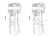
- FIGS. 2 - 8 show sectional views of different embodiments of medical, especially dental, fluid-operated handles with a control or regulating circuit for limiting, controlling or regulating the speed to a maximum or predetermined speed value, which has an actuating element which is supplied by an electrodynamic converter with electrical energy.
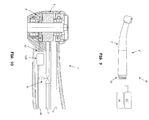
- FIG. 9 shows a medical, especially dental, treatment device with a control and / or regulating device for controlling and / or regulating the rotational speed of the rotary part.
- FIG. 10 and 11 show sectional views through medical, in particular dental, fluid-operated handles for use with a medical, in particular dental, treatment device of FIG. 9 ,
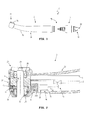
- the Indian FIG. 1 illustrated medical, in particular dental, fluid-operated handle 1 is formed as an elongated tubular instrument having at one end a connection 18 to one or more media sources, for example to a fluid source, in particular to a compressed air source.
- the handle 1 is in accordance FIG. 1 of two parts, namely a handpiece 2 and connectable to the handpiece 2 connecting part 3, which is designed for example as a coupling or adapter.
- the connecting part 3 and the handpiece 2 are detachably connectable to one another by means of a coupling device 19.
- FIG. 1 illustrated medical, in particular dental, fluid-operated handle 1 is formed as an elongated tubular instrument having at one end a connection 18 to one or more media sources, for example to a fluid source, in particular to a compressed air source.
- the handle 1 is in accordance FIG. 1 of two parts, namely a handpiece 2 and connectable to the handpiece 2 connecting part 3, which is designed for example as a coupling or adapter.
- connection 18 comprises a plurality of connecting pieces 20 which connects in the connection part 3 provided lines or channels with one or more media sources, in particular with a compressed air source, preferably with a liquid source.
- the lines or channels pass through the connecting part 3 and pass, preferably via the coupling device 19, the or the media to the handpiece 2.
- the handle 1 has only the handpiece 2 and that at the supply end of the handpiece. 2 a connection 18 similar or identical to one or more media sources is provided.
- a control or control circuit 8 for limiting, controlling or regulating the rotational speed of a rotary part 4 to a speed value which is described in detail below is, preferably completely, received in the handle 1.
- the control or regulating circuit 8 is either completely received in the handpiece 2 or at least parts of the control or regulating circuit 8, in particular an adjusting element 10, preferably a valve 10A, are located in the connecting part 3.
- the handpiece 2 comprises a curved or two angled portions having handle portion 21 and an adjoining headboard 2.
- a tool opening 23 (see FIG. 2 ), through which a tool is releasably inserted into the head part 22.
- the tool opening 23 is arranged laterally on the head part 22, so that the tool protrudes at an angle to the grip part 21 or its longitudinal axis from the head part 22.
- a push-button 24 is provided, which cooperates with a arranged in the head part 22 tool release device to release the tool from the head part 22.
- the handle 1 or the handpiece 2 may also have other known forms, for example, pistol-shaped or straight.
- a fluid line 5 for guiding the drive fluid in the direction of the head part 22 or to a arranged in the head part 22 rotating part 4 and a fluid line 6 for guiding the drive fluid from the head part 22nd away or from the disposed in the head part 22 rotating part 4 away.
- further media lines for example one or more media lines for cooling media, optical fibers or electrical lines extend through the handpiece 2.
- the fluid line 5 conveys the drive fluid, for example compressed air or water, to a drive unit 25 which has at least one rotatable rotary part 4 includes, for example, an impeller, a rotor of an air or vane motor, a shaft, a clamping device for the tool, etc.
- the rotary member 4 comprises an impeller 26 and a hollow shaft 27, to which the impeller 26 is fixed and in which a clamping device for the tool is arranged or which is part of the clamping device.
- the rotary member 4 and the tool connectable thereto are rotatably supported in the handpiece 2 by two roller bearings 28, 29.
- the rolling bearings 28, 29 are on non-rotatable components of the handpiece 2, for example, the outer sleeve 30 (see FIG. 1 ) stored.
- an electrodynamic converter or generator 9 which comprises a rotor and a stator.
- the stator is replaced by at least one, preferably a plurality of coils 11 and preferably a soft magnetic coil core around which the coils 11 are wound formed.
- the coils 11 and the coil core surround the magnetic element 12 having a rotor or are arranged close to the rotor.
- the rotor comprises according to FIG. 2 a magnetic element 12 connected to the rotary part 4 and rotatable with the rotary part 4, in particular a disk-shaped magnetic element having a bore through which the hollow shaft 27 protrudes.
- the impeller 26 is at least partially magnetic, in particular, the blades of the impeller 26 are magnetic.
- the fluid conduit 5 terminates near the rotary member 4 or the impeller 26 or outputs the drive fluid to the rotary member 4, in particular the impeller 26, or into a cavity of the head portion 22 in which the rotary member 4 or the impeller 26 are received.
- the impeller 26 By impinging the impeller 26 with the drive fluid from the fluid conduit 5, the impeller 26 is rotated and thus also the electrodynamic transducer 9 is activated and induced in the coils 11, a voltage.
- the height of the voltage induced in the coils 11 correlates with the rotational speed of the rotor, the rotary part 4 and the tool.
- the generator 9 is part of the control or regulating circuit 8 for limiting, controlling or regulating the rotational speed of the rotary part 4 and / or a tool connected to the rotary part 4.
- the control or regulating circuit 8 comprises in addition to the generator 9 an operable by means of electrical actuator 10, a switching and / or control device 14 and electrical lines 31, 31A which the generator 9 with the switching and / or control device 14 and Connect actuator 10.
- the actuating element 10 designed as a valve, in particular as a control valve or proportional valve, acts on the fluid flowing in the fluid line 5 by means of a positioning process.
- the adjusting element 10 changes the fluid pressure or the volume flow of the drive fluid, in particular by changing the inner diameter of the fluid line 5 which can be flowed through for the drive fluid, as a result of which the rotational speed of the rotary part 4 can be changed.
- the adjusting element 10 receives the electrical energy generated by the generator 9 via the electrical lines 31, 31A. A part of the energy supplied to the rotating part 4 by means of the drive fluid is thus used to operate the adjusting element 10. If the rotational speed of the rotary part 4 is too high, this reduces Actuator 10, the power supplied to the rotary member 4, for example, by reducing the fluid pressure or the volume flow of the drive fluid, whereby the rotational speed of the rotary member 4 decreases. If the rotational speed of the rotary member 4 is too low, the actuator 10 increases the energy supplied to the rotary member 4, for example, by increasing the fluid pressure or the volume flow of the driving fluid, whereby the rotational speed of the rotary member 4 increases.
- the control or regulating circuit 8 consists of the generator 9 driven by the rotary part 4, the adjusting element 10, the electrical lines 31, 31A for connecting the generator 9 to the adjusting element 10 and a part of the fluid line 5.
- the control or regulating circuit 8 additionally contains a switching and / or control device 14, which selectively supplies the actuating element 10 with electrical energy generated by the generator 9, in particular as a function of the rotational speed of the rotary part 4 and which in particular a device 32 for Determining the rotational speed of the rotary member 4, as in FIG. 2 is shown.
- switching and / or control device 14 is formed as a microcomputer or microcontroller 15 and electrically connected between the generator 9 and the actuator 10.
- the microcontroller 15 receives via the lines 31A, the electrical energy generated by the generator 9 and measures or determines a current parameter or value of the electrical energy, which correlates with the rotational speed of the rotary member 4, for example, the voltage or the current.
- the microcontroller 15 or at least parts of the microcontroller 15 thus determine the rotational speed of the rotary part 4 and form the device 32 for determining the rotational speed of the rotary part 4.
- the microcontroller 15 is further stored at least one limit value for the current parameter of the electrical energy, so that the Microcontroller 15 can compare the current parameter with the limit and depending on the ratio of the current parameter to the limit value, the actuator 10 is selectively supplied with electrical energy generated by the generator 9.
- the switching and / or control device 14 supplies the actuator 10 with electrical energy or closes the circuit between the generator 9 and the actuator 10 when the rotational speed of the rotary member 4 and thus the current parameter of the electrical energy generated by the generator 9 the limit reached or exceeded.
- the switching and / or control device 14 interrupts the supply of the actuating element 10 with electrical energy or opens the circuit between the generator 9 and the actuator 10 when the rotational speed of the rotary member 4 and thus the current parameter of the generator 9 generated electrical energy limit reached or fallen below.
- the actuating element 10 which can be operated by means of electrical energy is designed as a proportional valve, wherein the switching and / or control device 14 supplies the proportional valve with electrical energy in such a way that it carries out a continuous adjusting process as a function of the rotational speed of the rotary part 4.
- FIGS. 3 to 8 shown further embodiments of handpieces with a control or regulating circuit 8 for limiting, controlling or regulating the rotational speed of the rotating part similar in many respects to the structure and function of the handpiece 2 of FIG. 2 , For this reason, those features which describe the handpieces of the FIGS. 3 to 8 from the handpiece 2 of FIG. 2 differ.
- the control or regulating circuit 8 of the handpiece 2 of FIG. 3 differs by an alternative embodiment of the switching and / or control device 14 and / or by an alternative embodiment of the device 32 for determining the rotational speed of the rotary part 4:
- the device 32 consists of a radiation source 16, for example one or more light-emitting diodes, and a Radiation-receiving sensor 17, for example, a photodiode.
- the radiation source 16 can be supplied with electrical energy from the electrodynamic converter 9 via the electrical leads 33. If the electrical energy generated by the generator 9 reaches or exceeds a predetermined value, for example the switching voltage or forward voltage of the light-emitting diode, then the radiation source 16 emits electromagnetic radiation.
- the radiation-receiving sensor 17 is arranged and configured to receive this radiation emitted by the radiation source 16.
- the radiation-receiving sensor 17 and / or the switching and / or control device 14 close the circuit between the generator 9 and the actuator 10 , so that the adjusting element 10 can be supplied with the electrical energy generated by the generator 9.
- the radiation-receiving semiconductor element 17 and / or the switching and / or control device 14 opens the circuit between the generator 9 and the control element 10, so that the actuator 10 is no longer supplied with the electrical energy generated by the generator 9.
- the switching and / or control device 14 in turn has a microcontroller 15, which processes the signals of the sensor 17 and causes the closing of the circuit.
- the adjusting element 10, the sensor 17 and / or the switching and / or control device 14 are supplied via the electrical leads 31A with electrical energy generated by the generator 9.
- the devices 32 of the Figures 2 and 3 thus each use (directly or indirectly) the electrical energy generated by the generator 9 or a value thereof for determining the speed.
- a device 32 'for determining the rotational speed of the rotary member 4 is shown, which does not derive the rotational speed of the rotary member 4 from the electrical energy generated by the electrodynamic transducer 9.
- the device 32 ' comprises a sensor for detecting pressure fluctuations in the drive fluid, for example a microphone 34, which detects the sound emitted by the rotary part 4 and changes as a function of the rotational speed or changes in the flow velocity of the drive fluid in the fluid lines 5 or 6.
- the switching and / or control device 14 which in turn preferably has a microcontroller 15, processes the signals of the device 32 ', ie the microphone 34, and closes and opens or closes and opens the circuit between the generator 9 and the actuator 10 as a function of the rotational speed of the rotary part 4 / the signals of the device 32 '.
- the electrical energy generated by the generator 9 thus serves according to this embodiment, the electrical supply of the actuating element 10, the switching and / or control device 14 and the device 32 '(via the electrical lines 33), but not the determination of the rotational speed of the rotary part. 4
- the device 32 'for determining the rotational speed of the rotary part 4, which does not derive the rotational speed of the rotary part 4 from the electrical energy generated by the electrodynamic transducer 9, may alternatively also be formed by other components, for example by an optical detection device which comprises one of the reflected part 4, reflected or guided by the rotary part 4 detected radiation detected.
- Handpiece 2 shown comprises a fluid line 5 for guiding the drive fluid to the rotary member 4 and a secondary line 5A of the fluid line 5, which bypasses the provided in the fluid line 5 actuator 10.
- the secondary line 5A rises with respect to the flow direction of the drive fluid in front of the actuator 10 from the fluid line 5 and flows after the actuator 10 back into the fluid line 5.
- the actuator 10 which in turn is preferably designed as a valve disposed in the fluid line 6 for guiding the drive fluid from the rotary member 4 or head portion 22 away.
- the in the FIGS. 6 and 7 shown handpieces 2 each have a fluid branch line 7, which connects the fluid line 5 for guiding the drive fluid to the rotary member 4 and the fluid line 6 for guiding the drive fluid from the rotary member 4 or short.
- the adjusting element 10, which is preferably designed as a valve, is provided in or on the fluid branch line 7. If the actuating element 10 is not completely closed, then a part of the drive fluid flows directly from the fluid line 5 into the fluid line 6.
- the fluid branch line 7 opens into a pipe section 6A of the fluid line 6 or is connected to the same.
- the fluid line 6 for guiding the drive fluid from the rotary part 4 comprises only a short tube-like section 6B and is subsequently formed by the outer sleeve 30 of the handpiece 2.
- the used or flowing away from the rotary part 4 drive fluid thus flows through the cavity 13 in the outer sleeve 30.
- the fluid branch line 7 also opens in this embodiment in the cavity 13th
- the electrodynamic converter 9 supplies all the components of the control or regulating circuit 8 with electrical energy, in particular the control element 10, the switching and / or control device 14 and the device 32 for determining the rotational speed of the rotary part 4.
- the control or control circuit. 8 or the handle 1 thus require no electrical contacts or lines, which connects the handle 1 with an external, ie located outside of the handle 1, electrical energy source.
- FIGS. 9-11 illustrated treatment device 40 and handles 1 'constructed such that at least according to certain embodiments whose control or control circuit is at least partially operable with electrical energy, which is not formed by a generator 9 electrical energy source comes, in particular from an electrical energy source outside the handle 1 '.
- the treatment device 40 and handles 1 'of FIGS. 9-11 thus, they also have their own inventive aspect independent of the above-described operations.
- the medical, in particular dental, treatment device 40 comprises a handle 1 ', a rotatable part 4 provided in the handle 1' and rotatable by a drive fluid for driving a tool connectable to the rotary part 4, a device 42, 42A for determining the rotational speed of the rotary part 4 and a control and / or regulating device 41 for controlling and / or regulating the rotational speed of the rotary part 4, which is designed to compare the rotational speed of the rotary part 4 determined by the device 42 for determining the rotational speed with a default value and if the determined value deviates Speed of the default value to operate an actuator 10 which acts on the drive fluid to limit the rotational speed of the rotary member 4 to the default value or approximate the default value, wherein the actuator 10 is formed as an operable with electrical power actuator 10 which in the handle 1 'is arranged.
- the great advantage of the arrangement of the actuating element 10 in the handle 1 ' is that the distance between the actuator 10 and the rotary member 4 is very low, whereby the dead time, ie the time between the change of the speed and the reaction of the actuating element, is also very low.
- the entire control or regulating circuit which in particular the device 42, 42A for determining the rotational speed of the rotary member 4, the control and / or regulating device 41 and the actuating element 10, operable with electrical energy and with electrical signals, whereby the operation of the control or regulating circuit is accelerated or the dead time decreases even further.
- the adjusting element 10 is designed as a valve, in particular as a control valve, solenoid valve or proportional valve, or as a throttle.
- the in the FIG. 9 illustrated medical, in particular dental, treatment device 40 comprises a handle 1 ', which is constructed substantially the same as that in FIG. 1
- the handle 1 ' comprises either only a handpiece 2', which releasably via a coupling device 47 at least with a Fluid source 46 and optionally also at least connected to parts of the control and / or regulating device 41, as shown in the FIG. 9 is shown, or alternatively, a handpiece 2 'and a detachable connector part 3, as shown in the FIG. 1 can be seen.
- the medical, in particular dental, treatment device 40 further comprises a power source which provides electrical energy for operating the actuator 10, the energy source being provided either in the handle 1 'or outside the handle 1'.
- the energy source is arranged in the handle 1 ', it comprises, for example, a battery or a rechargeable accumulator or an electrodynamic transducer 9 which can be driven by the drive fluid.
- the electrodynamic transducer 9 or generator can preferably be driven directly or indirectly by the rotary part 4, as it is in FIG. 10 is shown.
- the generator 9 of the handle 1 'of FIG. 10 not only serves or not primarily the power supply of the actuating element 10, but is above all (due to the previously described correlation between the rotational speed of the rotary member 4 and the electrical energy generated by the generator 9) part of the device 42 for determining the speed of Rotary part 4.
- the electrical energy generated by the electrodynamic converter 9 is used exclusively to determine the rotational speed of the rotary part 4.
- the device 42 for determining the rotational speed of the rotary member 4 thus has a drivable by the rotary member 4 electrodynamic transducer 9, so that the rotational speed of the rotary part 4 can be derived from the electrical energy generated by the electrodynamic transducer 9.
- the device 42 is connected via electrical lines 48 to the control and / or regulating device 41 and either directly sends the electrical energy generated by the generator 9 to the control and / or regulating device 41 or modified by means of a component 42 A, the electrical generated by the generator 9 Energy.
- the component 42A is designed, for example, as an amplifier, rectifier, filter, analog-to-digital converter or microcontroller.
- the electrical energy modified by the component 42A is then conducted, in particular in the form of an electrical speed signal, via the electrical lines 48 to the control and / or regulating device 41.
- the control and / or regulating device 41 compares the electrical energy obtained from the device 42 or the speed signal with a fixed or by the User variable speed default value and operates at deviation of the determined speed of the default value by means of a, in particular electrical, control or regulating signal, the actuator 10 such that it acts on the drive fluid to approximate the speed of the rotary member 4 to the speed default value or on it limit as already described above.
- the treatment device 40 comprises a separate electrical energy source via (not shown electrical lines) the actuator 10 and optionally also the device 42 for determining the speed of Rotary part 4, in particular the component 42A, supplied with electrical energy.
- this electrical energy source is arranged outside the handle 1 ', in particular it is formed as part of the control and / or regulating device 41, wherein optionally the electrical lines 48 are also usable for transmitting the electrical energy.
- a releasable electrical connection between the actuator 10 and the electrical energy source is provided, in particular as part of the coupling device 47, for example, electrical sliding contacts or electrical plug contacts.
- control and / or regulating device 41 for controlling and / or regulating the rotational speed of the rotary part 4 completely in the handle 1 ', for example in the component 42A or as part of the component 42A.
- the generator 9 or the electrical energy generated by generator 9 again serves exclusively to determine the rotational speed of the rotary part 4, so that in this case the electrical lines 48 in particular the supply of the control and / or regulating device 41, the device 42 for determining Speed of the rotary member 4 and the actuating element 10 serve with electrical energy.
- the electrical energy is provided by an energy source outside the handle 1 '.
- the device 42 for determining the rotational speed of the rotary part 4 comprises a sensor for detecting pressure fluctuations in the drive fluid, in particular a microphone 34, the sound emitted by the rotary member 4 and varying depending on the speed of sound or changes in the flow velocity of the drive fluid detected.
- the structure of the device 42 corresponds to that in the FIG. 8 described construction of the device 32nd
- the device 42 for determining the rotational speed of the rotary part 4 is formed by an optical detection device 45 which, for example, detects a radiation emitted by the rotary part 4 or reflected by the rotary part 4 (see FIG FIG. 11 ).
- the device 42 comprises, for example, a radiation source 49, in particular a light-emitting diode, which emits radiation in the direction of the rotary part 4.
- a reflector 50 is provided on the rotary part, for example a reflective metal strip which reflects at least part of the radiation to a radiation sensor 51, for example an optical semiconductor, in particular a photodiode.
- the senor By the reflected radiation from the reflector 50 and detected by the sensor 51, the sensor is excited to emit a sensor signal which corresponds to the rotational speed.
- the component 42A which modifies the sensor signal.
- the sensor signal is forwarded to the control and / or regulating device 41, which determines the rotational speed on the basis of the sensor signal, compares with a rotational speed default value and if the determined rotational speed deviates from the default value by means of a, in particular electrical, control or regulating signal, the actuating element 10 operates.
- control and / or regulating device 41 for controlling and / or regulating the rotational speed of the rotary part 4 is provided at least partially outside the handle 1 '.
- the adjusting element 10 is arranged in or on the fluid line 5 for guiding the drive fluid from the fluid source 46 to the rotary part 4.
- the invention is not limited to the illustrated embodiments, but includes all embodiments that apply or include the basic, analogous operating principle of the invention. Furthermore, all features of all described and illustrated embodiments can be combined.
Landscapes
- Health & Medical Sciences (AREA)
- Engineering & Computer Science (AREA)
- General Health & Medical Sciences (AREA)
- Public Health (AREA)
- Dentistry (AREA)
- Epidemiology (AREA)
- Life Sciences & Earth Sciences (AREA)
- Animal Behavior & Ethology (AREA)
- Veterinary Medicine (AREA)
- Oral & Maxillofacial Surgery (AREA)
- Water Supply & Treatment (AREA)
- Physics & Mathematics (AREA)
- Fluid Mechanics (AREA)
- Mechanical Engineering (AREA)
- General Engineering & Computer Science (AREA)
- Dental Tools And Instruments Or Auxiliary Dental Instruments (AREA)
Abstract
Description
Die vorliegende Erfindung betrifft einen fluidbetriebenen medizinischen, insbesondere dentalen, Handgriff mit einem Drehteil und einem Steuer- oder Regelkreis zur Begrenzung, Steuerung oder Regelung der Drehzahl des Drehteils nach dem Oberbegriff des Anspruchs 1 und ein Verfahren zum Begrenzen, Steuern oder Regeln der Drehzahl des Drehteils.The present invention relates to a fluid-operated medical, in particular dental, handle with a rotary part and a control or regulating circuit for limiting, controlling or regulating the rotational speed of the rotary part according to the preamble of
Aus der Patentanmeldung US
Der vorliegenden Erfindung liegt die Aufgabe zugrunde, einen fluidbetriebenen medizinischen, insbesondere dentalen, Handgriff mit einer alternativen Vorrichtung zum Begrenzen, Steuern oder Regeln der Drehzahl zu schaffen.The present invention has for its object to provide a fluid-operated medical, in particular dental, handle with an alternative device for limiting, controlling or regulating the speed.
Gemäß einem Ausführungsbeispiel wird dies durch einen medizinischen, insbesondere dentalen, fluidbetriebenen Handgriff erreicht, der umfasst: Ein durch ein Antriebsfluid in Drehung versetzbares Drehteil zum Antrieb eines mit dem Drehteil verbindbaren Werkzeugs, eine Fluidleitung zur Leitung des Antriebsfluids zu dem oder von dem Drehteil oder eine Fluidzweigleitung, die mit einer Fluidleitung zur Leitung des Antriebsfluids zu dem oder von dem Drehteil verbunden ist, und einen Steuer- oder Regelkreis, welcher ausgebildet ist, die Drehzahl des Drehteils zu begrenzen, zu steuern oder zu regeln, wobei der Steuer- oder Regelkreis einen durch das Drehteil angetriebenen elektrodynamischen Wandler zur Erzeugung elektrischer Energie und zumindest ein Stellelement aufweist, welches ausgebildet ist, auf das in der Fluidleitung oder der Fluidzweigleitung fließende Antriebsfluid einzuwirken, wobei das zumindest eine Stellelement mit dem elektrodynamischen Wandler elektrisch derart verbunden ist, dass das zumindest eine Stellelement mit der von dem elektrodynamischen Wandler erzeugten elektrischen Energie zur Durchführung eines Stellvorgangs versorgbar ist.According to one embodiment, this is achieved by a medical, in particular dental, fluid-operated handle, comprising: a rotatable by a drive fluid rotatable rotary member for driving a connectable to the rotary member tool, a fluid line for guiding the drive fluid to or from the rotary member or a Fluid branch line, which is connected to a fluid line for guiding the drive fluid to or from the rotary member, and a control or regulating circuit which is adapted to limit the speed of the rotary member to control or regulating, wherein the control or regulating a Having driven by the rotary member electrodynamic transducer for generating electrical energy and at least one actuator which is adapted to act on the flowing in the fluid line or the fluid branch fluid drive fluid, wherein the at least one actuator is electrically connected to the electrodynamic converter such in that the at least one adjusting element can be supplied with the electrical energy generated by the electrodynamic converter for carrying out a setting process.
Der Steuer- oder Regelkreis ist somit als auf das Antriebsfluid des Drehteils einwirkender Steuer- oder Regelkreis oder pneumatischer Steuer- oder Regelkreis ausgebildet. Der Steuer- oder Regelkreis verändert mittels des Stellelements unmittelbar einen Parameter des Antriebsfluids, zum Beispiel den Fluiddruck oder den Volumenstrom, wodurch die Drehzahl des Drehteils begrenzt, gesteuert, geregelt oder verändert wird.The control or regulating circuit is thus designed as acting on the drive fluid of the rotary member control or control circuit or pneumatic control or control circuit. The control or regulating circuit changes by means of the adjusting element directly a parameter of the drive fluid, for example, the fluid pressure or the volume flow, whereby the rotational speed of the rotating part is limited, controlled, regulated or changed.
Bevorzugt ist das zumindest eine Stellelement mit dem elektrodynamischen Wandler elektrisch auch derart verbunden, dass das Einwirken des Stellelements auf das Antriebsfluid in Abhängigkeit von der Drehzahl des Drehteils erfolgt. Die von dem elektrodynamischen Wandler erzeugte elektrische Energie wird demgemäß für zwei Zwecke verwendet: Erstens, dient sie zum Einwirken des Stellelements auf das Antriebsfluid oder zum Durchführen eines auf das Antriebsfluid einwirkenden Stellvorgangs durch das Stellelement, sie wird also von dem Stellelement benötigt, damit dieses eine Stellbewegung durchführen kann. Zweitens, ist aufgrund der, insbesondere positiven, Korrelation zwischen der von dem elektrodynamischen Wandler erzeugten elektrischen Energie und der Drehzahl des Drehteils (mit steigender Drehzahl nimmt die erzeugte elektrische Energie zu bzw. mit fallender Drehzahl nimmt die erzeugte elektrische Energie ab) die Drehzahl des Drehteils bestimmbar, bevorzugt durch eine Schalt- und / oder Steuervorrichtung. Damit ist es gemäß einem besonders bevorzugten Ausführungsbeispiel möglich, das Einwirken des Stellelements auf das Antriebsfluid nur bei Erreichen oder Überschreiten eines vorbestimmten Drehzahlwerts oder eines vorbestimmten Wertes der von dem elektrodynamischen Wandler erzeugten elektrischen Energie (welche dann zumindest teilweise als Schalt- und / oder Steuersignal verwendet wird) auszuführen.Preferably, the at least one adjusting element is also electrically connected to the electrodynamic converter in such a way that the action of the adjusting element on the driving fluid is effected as a function of the rotational speed of the rotating part. The electrical energy generated by the electrodynamic transducer is thus used for two purposes: First, it serves to act on the actuating fluid by the actuator or to perform an actuating action on the driving fluid by the actuator, so it is required by the actuator to provide this one Can perform adjusting movement. Secondly, due to the, in particular positive, correlation between the electrical energy generated by the electrodynamic converter and the rotational speed of the rotary member (with increasing rotational speed, the electrical energy generated decreases or decreases with decreasing electrical energy), the rotational speed of the rotary member determinable, preferably by a switching and / or control device. This makes it possible according to a particularly preferred embodiment, the action of the actuating element on the drive fluid only when reaching or exceeding a predetermined speed value or a predetermined value of the electrical energy generated by the electrodynamic converter (which then at least partially used as a switching and / or control signal will).
Der elektrodynamische Wandler, im Folgenden auch als Generator bezeichnet, weist insbesondere einen Stator und einen Rotor auf, wobei der Rotor mit dem Drehteil verbunden ist oder als Teil des Drehteils ausgebildet ist. Das Drehteil umfasst zum Beispiel das durch das Antriebsfluid beaufschlagte Laufrad des Handgriffs, eine im Handgriff drehbar gelagerte Welle, zum Beispiel eine Hohlwelle zur lösbaren Aufnahme des Behandlungswerkzeugs, oder den Schaft eines im Handgriff aufnehmbaren Werkzeugs. Bevorzugt umfasst der Rotor ein Magnetelement und der Stator zumindest eine Spule, selbstverständlich ist jedoch auch eine umgekehrte Ausgestaltung möglich. Bevorzugt ist das Magnetelement am Drehteil vorgesehen ist, so dass das Magnetelement durch das Drehteil in Drehung versetzbar ist. Besonders bevorzugt ist das Magnetelement als Permanentmagnet ausgebildet, insbesondere als Scheibenmagnet, der am Drehteil befestigt ist. Alternativ ist das Drehteil selbst magnetisch, zum Beispiel aufgrund seiner Herstellung aus magnetischem Material oder durch Aufmagnetisierung.The electrodynamic converter, hereinafter also referred to as a generator, has in particular a stator and a rotor, wherein the rotor is connected to the rotary part or is formed as part of the rotary part. The rotary part comprises, for example, the impeller of the handle acted upon by the drive fluid, a shaft rotatably mounted in the handle, for example a hollow shaft for detachably receiving the treatment tool, or the shaft of a tool which can be received in the handle. Preferably, the rotor comprises a magnetic element and the stator at least one coil, of course, however, a reverse configuration is possible. Preferably, the magnetic element is provided on the rotary part, so that the magnetic element can be set in rotation by the rotary part. Particularly preferably, the magnetic element is designed as a permanent magnet, in particular as a disc magnet, which is fastened to the rotary part. Alternatively, the rotating part itself magnetic, for example due to its production from magnetic material or by magnetization.
Der Steuer- oder Regelkreis begrenzt, steuert oder regelt die Drehzahl des Drehteils und des damit verbindbaren Werkzeugs auf einen Maximal- oder Vorgabewert, insbesondere bei schwacher Belastung oder bei Leerlauf des Handgriffs, um damit die Lärmemission des Handgriffs zu verringern und die mechanische Belastung der im Handgriff befindlichen, das Drehteil lagernden Kugellager zu verringern. Auch ermöglicht die Drehzahlbegrenzung ein sanfteres Aufsetzen des Werkzeugs auf die Behandlungsstelle. Gemäß einem Ausführungsbeispiel ist der Steuer- oder Regelkreis ausgebildet, die Drehzahl des Drehteils und des Werkzeugs auf einen Wert im Bereich von etwa 300.000 - 150.000 Umdrehungen pro Minute, bevorzugt auf einen Wert im Bereich von etwa 275.000 - 200.000 Umdrehungen pro Minute, besonders bevorzugt auf in etwa 250.000 Umdrehungen pro Minute.The control or regulating circuit limits, controls or regulates the rotational speed of the rotating part and the tool that can be connected to a maximum or default value, especially under light load or idle of the handle, so as to reduce the noise emission of the handle and the mechanical load in the Handle to store the rotating part bearing ball bearings. Also, the speed limit allows a smoother placement of the tool on the treatment site. According to one embodiment, the control or regulating circuit is formed, the rotational speed of the rotary part and the tool to a value in the range of about 300,000 - 150,000 revolutions per minute, preferably to a value in the range of about 275,000 - 200,000 revolutions per minute, particularly preferably in about 250,000 revolutions per minute.
Gemäß einem Ausführungsbeispiel ist die zumindest eine Spule um einen weichmagnetischen Spulenkern gewickelt, der den magnetischen Fluss des Magnetelements des Generators bündelt und zur Spule lenkt. Insbesondere ist der aus einer oder mehreren, bevorzugt elektrisch voneinander isolierten, Schichten bestehende weichmagnetische Spulenkern ringförmig geformt und umgibt das Magnetelement an seinem Außenumfang. Damit wird, insbesondere wenn der elektrodynamische Wandler mehrere Spulen umfasst, deren Einbau im Handgriff erleichtert.According to one embodiment, the at least one coil is wound around a soft-magnetic coil core, which bundles the magnetic flux of the magnetic element of the generator and directs it to the coil. In particular, the soft-magnetic coil core consisting of one or more layers, which are preferably electrically insulated from one another, is annular in shape and surrounds the magnet element on its outer circumference. Thus, especially when the electrodynamic converter comprises a plurality of coils, their installation in the handle facilitates.
Gemäß einem anderen Ausführungsbeispiel ist das zumindest ein Stellelement als mittels elektrischer Energie betreibbares, insbesondere mechanisches, Stellelement ausgebildet, zum Beispiel als Ventil, insbesondere als Steuerventil oder als Proportionalventil, besonders bevorzugt als Magnetventil, oder als Drossel. Bevorzugt sind das Ventil oder die Drossel direkt an oder in der Leitung des Antriebsfluids zu oder von dem Drehteil oder direkt an oder in der Fluidzweigleitung vorgesehen.According to another exemplary embodiment, the at least one adjusting element is designed as an actuating element which can be operated by means of electrical energy, in particular as a mechanical control element, for example as a valve, in particular as a control valve or as a proportional valve, particularly preferably as a solenoid valve, or as a throttle. Preferably, the valve or the throttle are provided directly on or in the line of the drive fluid to or from the rotary member or directly on or in the fluid branch line.
Gemäß einem weiteren Ausführungsbeispiel verbindet die Fluidzweigleitung die Fluidleitung zur Leitung des Antriebsfluids zu dem Drehteil und die Fluidleitung zur Leitung des Antriebsfluids von dem Drehteil. Alternativ entspringt die Fluidzweigleitung an der Fluidleitung zur Leitung des Antriebsfluids zu dem Drehteil und mündet in einen Hohlraum einer hohlen Außenhülse des Handgriffs. Beiden Alternativen ermöglichen somit in vorteilhafter Weise, dass ein für den Antrieb des Drehteils nicht benötigter Anteil des Antriebsfluids über die Fluidzweigleitung ableitbar ist.According to a further embodiment, the fluid branch line connects the fluid line for guiding the drive fluid to the rotary part and the fluid line for guiding the drive fluid from the rotary part. Alternatively, the fluid branch line at the fluid line for the guidance of the drive fluid originates from the rotary part and opens into a hollow space of a hollow outer sleeve of the handle. Both alternatives thus make it possible in an advantageous manner for a portion of the drive fluid not required for driving the rotary part to be derivable via the fluid branch line.
Um einen gleichmäßigen Betrieb des Drehteils zu erzielen, weist gemäß einem Ausführungsbeispiel die Fluidleitung zur Leitung des Antriebsfluids zu dem oder von dem Drehteil eine Nebenleitung auf, welche das Stellelement umgeht, so dass zumindest eine Teil des Antriebsfluids an dem Stellelement vorbeileitbar ist. Die Versorgung des Drehteils mit Antriebsfluid setzt sich demgemäß aus einem kontinuierlich fließenden oder konstanten Antriebsfluidstrom und einem durch das Einwirken des Stellelements veränderbaren Antriebsfluidstrom zusammen.In order to achieve a uniform operation of the rotary part, according to one embodiment, the fluid line for guiding the drive fluid to or from the rotary part on a secondary line, which bypasses the actuating element, so that at least a portion of the drive fluid is vorbeileitbar on the adjusting element. The supply of the rotary part with drive fluid is accordingly composed of a continuously flowing or constant drive fluid flow and a drive fluid flow which can be varied by the action of the control element.
Gemäß einem Ausführungsbeispiel weist der Steuer- oder Regelkreis eine Schalt- und / oder Steuervorrichtung auf, welche zur selektiven Versorgung des zumindest einen Stellelements mit vom elektrodynamischen Wandler erzeugter elektrischer Energie in Abhängigkeit von der Drehzahl des Drehteils ausgebildet ist. Wie im Vorstehenden bereits erläutert ist es damit möglich, das Einwirken des Stellelements auf das Antriebsfluid von der Drehzahl des Drehteils abhängig zu machen oder das Einwirken des Stellelements auf das Antriebsfluid in Abhängigkeit von der Drehzahl des Drehteils zu steuern. Bevorzugt wird die von dem elektrodynamischen Wandler erzeugte elektrische Energie (aufgrund des direkten Zusammenhangs von Drehzahl des Drehteils und erzeugter elektrischer Energie) dabei zumindest teilweise auch als Schalt- und / oder Steuersignal verwendet. Bevorzugt lässt die Schalt- und / oder Steuervorrichtung die Versorgung des Stellelements mit von dem elektrodynamischen Wandler erzeugter elektrischer Energie oder das Einwirken des Stellelements auf das Antriebsfluid nur zu, wenn die Drehzahl des Drehteils einen vorbestimmten Wert erreicht oder überschreitet, zum Beispiel in etwa 200.000 U/min oder in etwa 250.000 U/min oder in etwa 275.000 U/min.According to one embodiment, the control or regulating circuit has a switching and / or control device which is designed to selectively supply the at least one actuating element with electrical energy generated by the electrodynamic converter as a function of the rotational speed of the rotary part. As already explained above, it is thus possible to make the action of the actuating element on the drive fluid dependent on the rotational speed of the rotary part or to control the action of the actuating element on the drive fluid as a function of the rotational speed of the rotary part. Preferably, the electrical energy generated by the electrodynamic converter (due to the direct relationship between rotational speed of the rotary part and generated electrical energy) is thereby at least partially also used as a switching and / or control signal. The switching and / or control device preferably allows the supply of the actuating element with electrical energy generated by the electrodynamic converter or the action of the actuating element on the drive fluid only when the rotational speed of the rotary part reaches or exceeds a predetermined value, for example in about 200,000 U or at about 250,000 rpm or about 275,000 rpm.
Gemäß einem bevorzugten Ausführungsbeispiel weist die Schalt- und / oder Steuervorrichtung eine Vorrichtung zur Ermittlung der Drehzahl des Drehteils auf. Die Vorrichtung zur Ermittlung der Drehzahl des Drehteils kann durch Bauteile gebildet sein, welche zum Beispiel direkt oder indirekt die von dem elektrodynamischen Wandler erzeugte elektrische Energie oder einen Wert der von dem elektrodynamischen Wandler erzeugten elektrischen Energie zur Ermittlung der Drehzahl des Drehteils verwenden. Derartige Bauteile können insbesondere durch einen Mikrocontroller oder durch eine Strahlungsquelle und ein Strahlung empfangendes Halbleiterelement gebildet sein, so wie dies im Folgenden noch detaillierter ausgeführt ist.According to a preferred embodiment, the switching and / or control device has a device for determining the rotational speed of the rotary part. The device for determining the rotational speed of the rotary part can be formed by components which, for example, directly or indirectly use the electrical energy generated by the electrodynamic converter or a value of the electrical energy generated by the electrodynamic converter to determine the rotational speed of the rotary part. Such components may in particular be formed by a microcontroller or by a radiation source and a radiation-receiving semiconductor element, as is explained in more detail below.
Alternativ kann die Vorrichtung zur Ermittlung der Drehzahl des Drehteils Bauteile aufweisen, welche die Drehzahl des Drehteils nicht von der von dem elektrodynamischen Wandler erzeugten elektrischen Energie ableiten. Derartige Bauteile können zum Beispiel durch einen Sensor zum Erfassen von Druckschwankungen im Antriebsfluid, insbesondere durch ein Mikrofon, das den vom Drehteil emittierten und sich in Abhängigkeit der Drehzahl verändernden Schall oder Änderungen der Strömungsgeschwindigkeit des Antriebsfluids detektiert, oder durch eine optische Erfassungsvorrichtung, welche zum Beispiel eine von dem Drehteil emittierte, reflektierte oder durch das Drehteil geleitete Strahlung detektiert, gebildet sein.Alternatively, the device for determining the rotational speed of the rotary part may have components which do not derive the rotational speed of the rotary part from the electrical energy generated by the electrodynamic converter. Such components can be detected, for example, by a sensor for detecting pressure fluctuations in the drive fluid, in particular by a microphone which detects the sound emitted by the rotary member and changing in dependence on the speed or changes in the flow velocity of the drive fluid, or by an optical detection device which, for example one of the rotating part emitted, reflected or guided by the rotary part detected radiation detected, be formed.
Gemäß einem besonders bevorzugten Ausführungsbeispiel umfasst die Schalt- und / oder Steuervorrichtung einen Mikrocontroller, welcher elektrisch mit dem elektrodynamischen Wandler verbunden ist und welcher ausgebildet ist, einen Wert der von dem elektrodynamischen Wandler erzeugten elektrischen Energie, insbesondere die Spannung, mit einem vorbestimmten Grenzwert zu vergleichen und die Versorgung des Stellelements mit von dem elektrodynamischen Wandler erzeugter elektrischer Energie zuzulassen, wenn der Wert der von dem elektrodynamischen Wandler erzeugten elektrischen Energie den vorbestimmten Grenzwert erreicht oder überschreitet.According to a particularly preferred embodiment, the switching and / or control device comprises a microcontroller, which is electrically connected to the electrodynamic converter and which is designed to compare a value of the electrical energy generated by the electrodynamic converter, in particular the voltage, with a predetermined limit and allowing the actuator to be supplied with electrical energy generated by the electrodynamic transducer when the value of the electrical energy generated by the electrodynamic transducer reaches or exceeds the predetermined limit.
Gemäß einem alternativen Ausführungsbeispiel umfasst die Schalt- und / oder Steuervorrichtung eine Strahlungsquelle und einen Strahlung empfangenden Sensor, insbesondere ein Halbleiterelement, zum Beispiel eine Photodiode, wobei die Strahlungsquelle von dem elektrodynamischen Wandler mit elektrischer Energie versorgbar ist und der Strahlung empfangende Sensor derart angeordnet ist, dass er von der Strahlungsquelle emittierte Strahlung empfängt, so dass ein Stromkreis zwischen dem elektrodynamischen Wandler und dem Stellelement schließbar ist und das Stellelement mit von dem elektrodynamischen Wandler erzeugter elektrischer Energie versorgbar ist, wenn der Sensor detektiert, dass die Strahlungsquelle Strahlung emittiert oder Strahlung emittiert, welche einen vorbestimmten Grenzwert überschreitet. Die Strahlungsquelle ist insbesondere derart ausgebildet, dass sie erst dann Strahlung emittiert, wenn die ihr zugeführte, vom Generator erzeugte, elektrische Energie einen Schwellenwert überschreitet. Die Strahlungsquelle ist zum Beispiel als Leuchtdiode ausgebildet.According to an alternative embodiment, the switching and / or control device comprises a radiation source and a radiation-receiving sensor, in particular a semiconductor element, for example a photodiode, wherein the radiation source can be supplied with electrical energy by the electrodynamic converter and the radiation-receiving sensor is arranged in such a way that it receives radiation emitted by the radiation source so that a circuit between the electrodynamic converter and the control element can be closed and the control element can be supplied with electrical energy generated by the electrodynamic converter if the sensor detects that the radiation source emits radiation or emits radiation, which exceeds a predetermined limit. In particular, the radiation source is designed such that it does not emit radiation until the electrical energy supplied to it by the generator exceeds a threshold value. The radiation source is designed, for example, as a light-emitting diode.
Gemäß einem bevorzugten Ausführungsbeispiel umfasst der elektrodynamische Wandler mehrere Spulen, wobei zumindest eine erste Spule ausschließlich für die Versorgung des Stellelements mit elektrischer Energie vorgesehen ist, insbesondere zur Durchführung des Stellvorgangs, und wobei zumindest eine zweite Spule ausschließlich für die Versorgung der Schalt- und / oder Steuervorrichtung mit elektrischer Energie vorgesehen ist, insbesondere zur Erzeugung eines Schalt- und / oder Steuersignals für das Stellelement. Auf diese Weise wird, insbesondere wenn mehrere erste Spulen ausschließlich für die Versorgung des Stellelements mit elektrischer Energie vorgesehen sind, eine zuverlässige und ausreichende Energieversorgung des Stellelements gewährleistet.According to a preferred embodiment, the electrodynamic converter comprises a plurality of coils, wherein at least one first coil is provided exclusively for the supply of the actuating element with electrical energy, in particular for Carrying out the setting process, and wherein at least one second coil is provided exclusively for the supply of the switching and / or control device with electrical energy, in particular for generating a switching and / or control signal for the actuating element. In this way, in particular if a plurality of first coils are provided exclusively for the supply of the actuating element with electrical energy, a reliable and sufficient energy supply of the actuating element is ensured.
Um eine zuverlässige Funktion des Stellelements und bevorzugt auch der Schalt- und / oder Steuervorrichtung zu erreichen, weist gemäß einem Ausführungsbeispiel der Steuer- oder Regelkreis eine Vorrichtung zum Gleichrichten der von dem elektrodynamischen Wandler erzeugten elektrischen Energie auf, so dass das Stellelement und bevorzugt auch die Schalt- und / oder Steuervorrichtung mit Gleichstrom versorgbar sind.In order to achieve reliable operation of the actuating element and preferably also of the switching and / or control device, according to one embodiment of the control or regulating circuit comprises a device for rectifying the electrical energy generated by the electrodynamic converter, so that the actuating element and preferably also the Switching and / or control device can be supplied with DC.
Gemäß einem bevorzugten Ausführungsbeispiel ist der gesamte Steuer- oder Regelkreis im Handgriff und / oder in einem an den Handgriff anschließbaren Anschlussteil, insbesondere in einem Adapter oder in einem Kupplungselement, aufgenommen und ist das Stellelement, und besonders bevorzugt auch die Schalt- und / oder Steuervorrichtung, von einer außerhalb des Handgriffs und / oder des Anschlussteils angeordneten elektrischen Energiequelle unabhängig. Damit ist in vorteilhafter Weise der Steuer- oder Regelkreis voll funktionsfähig, wenn der Handgriff an eine rein pneumatische Versorgungseinheit angeschlossen ist.According to a preferred embodiment, the entire control or regulating circuit in the handle and / or in a connectable to the handle connection part, in particular in an adapter or in a coupling element, received and is the control element, and particularly preferably also the switching and / or control device , independently of an electrical energy source arranged outside the handle and / or the connection part. Thus, the control or regulating circuit is fully functional in an advantageous manner, when the handle is connected to a purely pneumatic supply unit.
Ein Verfahren zur Begrenzung, Steuerung oder Regelung der Drehzahl eines medizinischen, insbesondere dentalen, fluidbetriebenen Handgriffs ist dadurch definiert, dass der durch das Drehteil angetriebenen elektrodynamischen Wandler elektrische Energie erzeugt und dass das Stellelement auf das in der Fluidleitung oder der Fluidzweigleitung fließende Antriebsfluid einwirkt, um die Drehzahl zu begrenzen, zu steuern oder zu regeln, wobei das zumindest eine Stellelement mit dem elektrodynamischen Wandler elektrisch derart verbunden ist, dass das zumindest eine Stellelement zur Durchführung eines Stellvorgangs mit der von dem elektrodynamischen Wandler erzeugten elektrischen Energie versorgt wird.A method for limiting, controlling or regulating the rotational speed of a medical, in particular dental, fluid-operated handle is defined in that the electrodynamic converter driven by the rotary part generates electrical energy and in that the actuating element acts on the drive fluid flowing in the fluid line or the fluid branch line to limit, control or regulate the speed, wherein the at least one adjusting element is electrically connected to the electrodynamic converter in such a way that the at least one actuating element is supplied with the electrical energy generated by the electrodynamic converter for carrying out a setting process.
Die Erfindung wird nachfolgend anhand bevorzugter Ausführungsbeispiele und Bezug nehmend auf die beigefügten Zeichnungen erläutert:
-
Figur 1
-
FIG. 1 shows an external view of a medical, in particular dental, fluid-operated handle with a control or regulating circuit for limiting, controlling the speed to a maximum or predetermined speed value.
Die
Die
Die
Der in der
Ein im Weiteren noch detailliert beschriebener Steuer- oder Regelkreis 8 zur Begrenzung, Steuerung oder Regelung der Drehzahl eines Drehteils 4 auf einen Drehzahlwert ist, bevorzugt vollständig, im Handgriff 1 aufgenommen. Gemäß unterschiedlichen Ausführungsformen ist der Steuer- oder Regelkreis 8 entweder vollständig im Handstück 2 aufgenommen oder zumindest Teile des Steuer- oder Regelkreises 8, insbesondere ein Stellelement 10, bevorzugt ein Ventil 10A, befinden sich im Anschlussteil 3.A control or
Das Handstück 2 umfasst einen gebogenen oder zwei gewinkelt zueinander angeordnete Abschnitte aufweisenden Griffteil 21 und einen daran anschließenden Kopfteil 2. Am Kopfteil 22 ist eine Werkzeugöffnung 23 (siehe
Wie aus der
Gemäß der Ausführungsform des Handstücks 2 nach
Im Kopfteil 22 des Handstücks 2 ist ein elektrodynamischer Wandler oder Generator 9 vorgesehen, der einen Rotor und einen Stator umfasst. Der Stator wird durch zumindest eine, bevorzugt mehrere, Spulen 11 und bevorzugt einen weichmagnetischen Spulenkern, um den die Spulen 11 gewickelt sind, gebildet. Die Spulen 11 und der Spulenkern umgeben den ein Magnetelement 12 aufweisenden Rotor oder sind nahe des Rotors angeordnet. Der Rotor umfasst gemäß
Die Fluidleitung 5 endet nahe des Drehteils 4 oder des Laufrads 26 oder gibt das Antriebsfluid an das Drehteil 4, insbesondere das Laufrad 26, oder in einen Hohlraum des Kopfteils 22, in dem das Drehteil 4 oder das Laufrad 26 aufgenommen sind, ab. Durch Beaufschlagen des Laufrads 26 mit dem Antriebsfluid aus der Fluidleitung 5 wird das Laufrad 26 in Drehung versetzt und somit auch der elektrodynamische Wandler 9 aktiviert und in den Spulen 11 eine Spannung induziert. Die Höhe der in den Spulen 11 induzierten Spannung korreliert dabei mit der Drehzahl des Rotors, des Drehteils 4 und des Werkzeugs.The
Der Generator 9 ist Teil des Steuer- oder Regelkreises 8 zur Begrenzung, Steuerung oder Regelung der Drehzahl des Drehteils 4 und / oder eines mit dem Drehteil 4 verbundenen Werkzeugs. Gemäß dem in der
Zur Durchführung des Stellvorgangs erhält das Stellelement 10 über die elektrischen Leitungen 31, 31A die von dem Generator 9 erzeugte elektrische Energie. Ein Teil der dem Drehteil 4 mittels des Antriebsfluids zugeführten Energie wird somit zum Betrieb des Stellelements 10 verwendet. Ist die Drehzahl des Drehteils 4 zu hoch, so verringert das Stellelement 10 die dem Drehteil 4 zugeführte Energie, zum Beispiel durch Verringern des Fluidrucks oder des Volumenstroms des Antriebsfluids, wodurch die Drehzahl des Drehteils 4 abnimmt. Ist die Drehzahl des Drehteils 4 zu niedrig, so erhöht das Stellelement 10 die dem Drehteil 4 zugeführte Energie, zum Beispiel durch Erhöhen des Fluiddrucks oder des Volumenstroms des Antriebsfluids, wodurch die Drehzahl des Drehteils 4 ansteigt.To carry out the adjusting operation, the adjusting
Gemäß einem einfachen, nicht dargestellten Ausführungsbeispiel besteht der Steuer- oder Regelkreises 8 aus dem durch das Drehteil 4 antreibbaren Generator 9, dem Stellelement 10, den elektrischen Leitungen 31, 31A zur Verbindung des Generators 9 mit dem Stellelement 10 und einem Teil der Fluidleitung 5. Bevorzugt enthält der Steuer- oder Regelkreises 8 jedoch zusätzlich eine Schalt- und / oder Steuervorrichtung 14, welche das Stellelement 10 selektiv mit von dem Generator 9 erzeugter elektrischer Energie versorgt, insbesondere in Abhängigkeit von der Drehzahl des Drehteils 4 und welche insbesondere eine Vorrichtung 32 zur Ermittlung der Drehzahl des Drehteils 4 aufweist, so wie dies in
Der Mikrocontroller 15 erhält über die Leitungen 31A die vom Generator 9 erzeugte elektrische Energie und misst oder bestimmt einen aktuellen Parameter oder Wert der elektrischen Energie, welcher mit der Drehzahl des Drehteils 4 korreliert, zum Beispiel die Spannung oder die Stromstärke. Der Mikrocontroller 15 oder zumindest Teile des Mikrocontrollers 15 bestimmen somit die Drehzahl des Drehteils 4 und bilden die Vorrichtung 32 zur Ermittlung der Drehzahl des Drehteils 4. Im Mikrocontroller 15 ist des Weiteren zumindest ein Grenzwert für den aktuellen Parameter der elektrischen Energie gespeichert, so dass der Mikrocontroller 15 den aktuellen Parameter mit dem Grenzwert vergleichen kann und in Abhängigkeit des Verhältnisses des aktuellen Parameters zu dem Grenzwert das Stellelements 10 selektiv mit von dem Generator 9 erzeugter elektrischer Energie versorgt. Zum Beispiel versorgt die Schalt- und / oder Steuervorrichtung 14 das Stellelement 10 mit elektrischer Energie oder schließt den Stromkreis zwischen dem Generator 9 und dem Stellelement 10, wenn die Drehzahl des Drehteils 4 und somit der aktuelle Parameter der vom Generator 9 erzeugten elektrischen Energie den Grenzwert erreicht oder überschreitet. Alternativ unterbricht die Schalt- und / oder Steuervorrichtung 14 die Versorgung des Stellelements 10 mit elektrischer Energie oder öffnet den Stromkreis zwischen dem Generator 9 und dem Stellelement 10, wenn die Drehzahl des Drehteils 4 und somit der aktuelle Parameter der vom Generator 9 erzeugten elektrischen Energie den Grenzwert erreicht oder unterschreitet. Besonders bevorzugt ist das mittels elektrischer Energie betreibbare Stellelement 10 als Proportionalventil ausgebildet, wobei die Schalt- und / oder Steuervorrichtung 14 das Proportionalventil derart mit elektrischer Energie versorgt, dass dieses in Abhängigkeit der Drehzahl des Drehteils 4 einen stetigen Stellvorgang ausführt.The
Die in den
Der Steuer- oder Regelkreis 8 des Handstücks 2 der
Die Vorrichtungen 32 der
Die Vorrichtung 32' zur Ermittlung der Drehzahl des Drehteils 4, welche die Drehzahl des Drehteils 4 nicht von der von dem elektrodynamischen Wandler 9 erzeugten elektrischen Energie ableitet, kann alternativ auch durch andere Bauteile gebildet sein, zum Beispiel durch eine optische Erfassungsvorrichtung, welche eine von dem Drehteil 4 emittierte, reflektierte oder durch das Drehteil 4 geleitete Strahlung detektiert.The device 32 'for determining the rotational speed of the
Das in der
Bei dem Ausführungsbeispiel des Handstücks 2 gemäß
Die in den
Bei dem Handstück 2 der
Bei den in den
Im Gegensatz dazu sind die in den
Die medizinische, insbesondere dentale, Behandlungsvorrichtung 40 umfasst einen Handgriff 1', ein im Handgriff 1' vorgesehenes und durch ein Antriebsfluid in Drehung versetzbares Drehteil 4 zum Antrieb eines mit dem Drehteil 4 verbindbaren Werkzeugs, eine Vorrichtung 42, 42A zur Ermittlung der Drehzahl des Drehteils 4 und eine Steuer- und / oder Regelvorrichtung 41 zur Steuerung und / oder Regelung der Drehzahl des Drehteils 4, welche ausgebildet ist, die von der Vorrichtung 42 zur Ermittlung der Drehzahl ermittelte Drehzahl des Drehteils 4 mit einem Vorgabewert zu vergleichen und bei Abweichen der ermittelten Drehzahl von dem Vorgabewert ein Stellelement 10 zu betreiben, welches auf das Antriebsfluid einwirkt, um die Drehzahl des Drehteils 4 auf den Vorgabewert zu begrenzen oder dem Vorgabewert anzunähern, wobei das Stellelement 10 als ein mit elektrischer Energie betreibbares Stellelement 10 ausgebildet ist, das im Handgriff 1' angeordnet ist.The medical, in particular dental,
Der große Vorteil der Anordnung des Stellelements 10 in dem Handgriff 1' besteht darin, dass die Entfernung zwischen dem Stellelement 10 und dem Drehteil 4 sehr gering ist, wodurch die Totzeit, also die Zeitspanne zwischen der Änderung der Drehzahl und der Reaktion des Stellelements darauf, ebenfalls sehr gering ist. Damit wird in vorteilhafter Weise ein stabiler Betrieb der Behandlungsvorrichtung 40 erzielt, insbesondere ohne Gefahr des Aufschwingens des Steuer- oder Regelkreises. Bevorzugt ist der gesamte Steuer- oder Regelkreis, welcher insbesondere die Vorrichtung 42, 42A zur Ermittlung der Drehzahl des Drehteils 4, die Steuer- und / oder Regelvorrichtung 41 und das Stellelement 10 umfasst, mit elektrischer Energie und mit elektrischen Signalen betreibbar, wodurch der Betrieb des Steuer- oder Regelkreises noch beschleunigt wird oder die Totzeit noch weiter abnimmt.The great advantage of the arrangement of the
Gemäß einem Ausführungsbeispiel ist das Stellelement 10 als Ventil, insbesondere als Steuerventil, Magnetventil oder Proportionalventil, oder als Drossel ausgebildet.According to one embodiment, the adjusting
Die in der
Gemäß einem Ausführungsbeispiel umfasst die medizinische, insbesondere dentale, Behandlungsvorrichtung 40 des Weiteren eine Energiequelle, welche elektrische Energie zum Betreiben des Stellelements 10 zur Verfügung stellt, wobei die Energiequelle entweder im Handgriff 1' oder außerhalb des Handgriffs 1' vorgesehen ist. Ist die Energiequelle im Handgriff 1' angeordnet, so umfasst sie zum Beispiel eine Batterie oder einen wiederaufladbaren Akkumulator oder einen durch das Antriebsfluid antreibbaren elektrodynamischen Wandler 9. Der elektrodynamischen Wandler 9 oder Generator ist bevorzugt direkt oder indirekt durch das Drehteil 4 antreibbar, so wie dies in
Der Generator 9 des Handgriffs 1' der
Die Steuer- und / oder Regelvorrichtung 41 vergleicht die von der Vorrichtung 42 erhaltene elektrische Energie oder das Drehzahlsignal mit einem fixen oder durch den Anwender veränderbaren Drehzahl-Vorgabewert und betreibt bei Abweichen der ermittelten Drehzahl von dem Vorgabewert mittels einem, insbesondere elektrischen, Steuer- oder Regelsignal das Stellelement 10 derart, dass dieses auf das Antriebsfluid einwirkt, um die Drehzahl des Drehteils 4 dem Drehzahl-Vorgabewert anzunähern oder darauf zu begrenzen, so wie dies ebenfalls im Vorstehenden bereits beschrieben wurde.The control and / or regulating
Dient die vom elektrodynamischen Wandler 9 erzeugte elektrische Energie ausschließlich der Ermittlung der Drehzahl des Drehteils 4, so umfasst die Behandlungsvorrichtung 40 eine separate elektrische Energiequelle, die über (nicht dargestellte elektrische Leitungen) das Stellelement 10 und gegebenenfalls auch die Vorrichtung 42 zur Ermittlung der Drehzahl des Drehteils 4, insbesondere das Bauteil 42A, mit elektrischer Energie versorgt. Bevorzugt ist diese elektrische Energiequelle außerhalb des Handgriffs 1' angeordnet, insbesondere ist sie als Teil der Steuer- und / oder Regelvorrichtung 41 ausgebildet, wobei gegebenenfalls die elektrischen Leitungen 48 auch zur Übertragung der elektrischen Energie verwendbar sind. Besonders bevorzugt ist eine lösbare elektrische Verbindung zwischen dem Stellelement 10 und der elektrischen Energiequelle vorgesehen, insbesondere als Teil der Kupplungsvorrichtung 47, zum Beispiel elektrische Schleifkontakte oder elektrische Steckkontakte.Serves the electrical energy generated by the
Alternativ ist es auch denkbar, die Steuer- und / oder Regelvorrichtung 41 zur Steuerung und / oder Regelung der Drehzahl des Drehteils 4 vollständig im Handgriff 1' vorzusehen, zum Beispiel in dem Bauteil 42A oder als Teil des Bauteils 42A. Bevorzugt dient der Generator 9 oder die von Generator 9 erzeugte elektrische Energie wiederum ausschließlich der Ermittlung der Drehzahl des Drehteils 4, so dass in diesem Fall die elektrischen Leitungen 48 insbesondere der Versorgung der Steuer- und / oder Regelvorrichtung 41, der Vorrichtung 42 zur Ermittlung der Drehzahl des Drehteils 4 und des Stellelements 10 mit elektrischer Energie dienen. Besonders bevorzugt ist die elektrische Energie von einer Energiequelle außerhalb des Handgriffs 1' zur Verfügung gestellt.Alternatively, it is also conceivable to provide the control and / or regulating
Gemäß einem alternativen Ausführungsbeispiel weist die Vorrichtung 42 zur Ermittlung der Drehzahl des Drehteils 4 einen Sensor zum Erfassen von Druckschwankungen im Antriebsfluid auf, insbesondere ein Mikrofon 34, das den vom Drehteil 4 emittierten und sich in Abhängigkeit der Drehzahl verändernden Schall oder Änderungen der Strömungsgeschwindigkeit des Antriebsfluids detektiert. Der Aufbau der Vorrichtung 42 entspricht dem in der
Gemäß einem weiteren Ausführungsbeispiel ist die Vorrichtung 42 zur Ermittlung der Drehzahl des Drehteils 4 durch eine optische Erfassungsvorrichtung 45 gebildet, welche zum Beispiel eine von dem Drehteil 4 emittierte, reflektierte oder durch das Drehteil 4 geleitete Strahlung detektiert (siehe
Die Versorgung des Stellelements 10, der Vorrichtung 42 zur Ermittlung der Drehzahl des Drehteils 4 und gegebenenfalls des Bauteils 42A, welches bevorzugt auch die Steuer- und / oder Regelvorrichtung 41 umfasst, mit elektrischer Energie erfolgt durch eine, bevorzugt außerhalb des Handgriffs 1' vorgesehene, elektrische Energiequelle über die elektrischen Leitungen 48.The supply of the
Gemäß einem Ausführungsbeispiel ist die Steuer- und / oder Regelvorrichtung 41 zur Steuerung und / oder Regelung der Drehzahl des Drehteils 4 zumindest teilweise außerhalb des Handgriffs 1' vorgesehen.According to one embodiment, the control and / or regulating
In den
In den
Die Erfindung ist nicht auf die dargestellten Ausführungsbeispiele beschränkt, sondern umfasst alle Ausführungen, die das prinzipielle, sinngemäße Funktionsprinzip der Erfindung anwenden oder beinhalten. Des Weiteren sind alle Merkmale aller beschriebenen und dargestellten Ausführungsbeispiele miteinander kombinierbar.The invention is not limited to the illustrated embodiments, but includes all embodiments that apply or include the basic, analogous operating principle of the invention. Furthermore, all features of all described and illustrated embodiments can be combined.
Claims (29)
der Steuer- oder Regelkreis (8) aufweist: Einen durch das Drehteil (4) angetriebenen elektrodynamischen Wandler (9) zur Erzeugung elektrischer Energie und zumindest ein Stellelement (10), welches ausgebildet ist, auf das in der Fluidleitung (5, 6) oder der Fluidzweigleitung (7) fließende Antriebsfluid einzuwirken, wobei das zumindest eine Stellelement (10) mit dem elektrodynamischen Wandler (9) elektrisch derart verbunden ist, dass das zumindest eine Stellelement (10) zur Durchführung eines Stellvorgangs mit der von dem elektrodynamischen Wandler (9) erzeugten elektrischen Energie versorgbar ist.Medical, in particular dental, fluid-operated handle (1), comprising: a rotatable by a drive fluid rotatable part (4) for driving a rotatable part (4) connectable tool, a fluid line (5, 6) for guiding the drive fluid to the or of the rotary member (4) or a fluid branch pipe (7) connected to a fluid line (5, 6) for guiding the driving fluid to or from the rotary member (4), and a control circuit (8) formed is to limit the speed of the rotary member (4) or to control or regulated, characterized in that
the control or regulating circuit (8) comprises: an electrodynamic transducer (9) driven by the rotary part (4) for generating electrical energy and at least one actuating element (10) which is formed on the in the fluid line (5, 6) or The drive fluid flowing fluid branch line (7), wherein the at least one adjusting element (10) with the electrodynamic transducer (9) is electrically connected such that the at least one adjusting element (10) for performing a positioning process with the of the electrodynamic transducer (9) generated electrical energy is supplied.
der elektrodynamische Wandler (9) zumindest eine Spule (11) und ein Magnetelement (12) umfasst, wobei bevorzugt das Magnetelement (12) am Drehteil (4) vorgesehen ist, so dass das Magnetelement (12) durch das Drehteil (4) in Drehung versetzbar ist.Medical, in particular dental, fluid-operated handle (1) according to claim 1, characterized in that
the electrodynamic converter (9) comprises at least one coil (11) and a magnetic element (12), wherein preferably the magnetic element (12) is provided on the rotary part (4) so that the magnetic element (12) rotates through the rotary part (4) is displaceable.
die zumindest eine Spule (11) um einen weichmagnetischen Spulenkern gewickelt ist.Medical, in particular dental, fluid-operated handle (1), according to claim 2, characterized in that
the at least one coil (11) is wound around a soft-magnetic coil core.
das Stellelement (10) als Ventil (10A), insbesondere als Steuerventil oder als Proportionalventil, oder als Drossel ausgebildet ist.Medical, in particular dental, fluid-operated handle (1) according to one of the preceding claims, characterized in that
the adjusting element (10) is designed as a valve (10A), in particular as a control valve or as a proportional valve, or as a throttle.
die Fluidzweigleitung (7) die Fluidleitung (5) zur Leitung des Antriebsfluids zu dem Drehteil (4) und die Fluidleitung (6) zur Leitung des Antriebsfluids von dem Drehteil (4) verbindet oder dass die Fluidzweigleitung (7) an der Fluidleitung (5) zur Leitung des Antriebsfluids zu dem Drehteil (4) entspringt und in einen Hohlraum (13) einer hohlen Außenhülse des Handgriffs (1) mündet.Medical, in particular dental, fluid-operated handle (1) according to one of the preceding claims, characterized in that
the fluid branch line (7) connects the fluid line (5) for guiding the drive fluid to the rotary part (4) and the fluid line (6) for conducting the drive fluid from the rotary part (4) or the fluid branch line (7) to the fluid line (5) to the line of the drive fluid to the rotary member (4) springs and in a cavity (13) of a hollow outer sleeve of the handle (1) opens.
die Fluidleitung (5, 6) zur Leitung des Antriebsfluids zu dem oder von dem Drehteil (4) eine Nebenleitung (5A) aufweist, welche das Stellelement (10) umgeht, so dass zumindest eine Teil des Antriebsfluids an dem Stellelement (10) vorbeileitbar ist.Medical, in particular dental, fluid-operated handle (1) according to one of claims 1 - 4, characterized in that
the fluid line (5, 6) for guiding the drive fluid to or from the rotary part (4) has a secondary line (5A) which bypasses the actuating element (10), so that at least a part of the drive fluid can be conducted past the actuating element (10) ,
der Steuer- oder Regelkreis (8) eine Schalt- und / oder Steuervorrichtung (14) aufweist, welche zur selektiven Versorgung des zumindest einen Stellelements (10) mit vom elektrodynamischen Wandler (9) erzeugter elektrischer Energie in Abhängigkeit von der Drehzahl des Drehteils (4) ausgebildet ist.Medical, in particular dental, fluid-operated handle (1) according to one of the preceding claims, characterized in that
the control or regulating circuit (8) has a switching and / or control device (14) which is provided for selectively supplying the at least one actuating element (10) with electrical energy generated by the electrodynamic converter (9) as a function of the rotational speed of the rotary part (4 ) is trained.
die Schalt- und / oder Steuervorrichtung (14) eine Vorrichtung (32, 32') zur Ermittlung der Drehzahl des Drehteils (4) aufweist.Medical, in particular dental, fluid-operated handle (1) according to claim 7, characterized in that
the switching and / or control device (14) has a device (32, 32 ') for determining the rotational speed of the rotary part (4).
die Schalt- und / oder Steuervorrichtung (14) einen Mikrocontroller (15) umfasst, welcher elektrisch mit dem elektrodynamischen Wandler (9) verbunden ist und welcher ausgebildet ist, einen Wert der von dem elektrodynamischen Wandler (9) erzeugten elektrischen Energie mit einem vorbestimmten Grenzwert zu vergleichen und die Versorgung des Stellelements (10) mit von dem elektrodynamischen Wandler (9) erzeugter elektrischer Energie zuzulassen, wenn der Wert der von dem elektrodynamischen Wandler (9) erzeugten elektrischen Energie den vorbestimmten Grenzwert erreicht oder überschreitet.Medical, in particular dental, fluid-operated handle (1) according to claim 7 or 8, characterized in that
the switching and / or control device (14) comprises a microcontroller (15) which is electrically connected to the electrodynamic transducer (9) and which is designed to have a value of the electrical energy generated by the electrodynamic transducer (9) at a predetermined limit and to allow the supply of the actuator (10) with electrical energy generated by the electrodynamic transducer (9) when the value of the electrical energy generated by the electrodynamic transducer (9) reaches or exceeds the predetermined limit.
die Schalt- und / oder Steuervorrichtung (14) eine Strahlungsquelle (16) und einen Strahlung empfangenden Sensor (17), insbesondere ein Halbleiterelement, zum Beispiel eine Photodiode, umfasst, wobei die Strahlungsquelle (16) von dem elektrodynamischen Wandler (9) mit elektrischer Energie versorgbar ist und der Sensor (17) derart angeordnet ist, dass er von der Strahlungsquelle (16) emittierte Strahlung empfängt, so dass ein Stromkreis zwischen dem elektrodynamischen Wandler (9) und dem Stellelement (10) schließbar ist und das Stellelement (10) mit von dem elektrodynamischen Wandler (9) erzeugter elektrischer Energie versorgbar ist, wenn der Sensor (17) detektiert, dass die Strahlungsquelle (16) Strahlung emittiert oder Strahlung emittiert, welche einen vorbestimmten Grenzwert überschreitet.Medical, in particular dental, fluid-operated handle (1) according to claim 7 or 8, characterized in that
the switching and / or control device (14) comprises a radiation source (16) and a radiation-receiving sensor (17), in particular a semiconductor element, for example a photodiode, wherein the radiation source (16) of the electrodynamic transducer (9) with electrical Energy is supplied and the sensor (17) is arranged such that it receives from the radiation source (16) emitted radiation, so that a circuit between the electrodynamic transducer (9) and the adjusting element (10) can be closed and the adjusting element (10) With electrical energy generated by the electrodynamic transducer (9) can be supplied if the sensor (17) detects that the radiation source (16) emits radiation or emits radiation which exceeds a predetermined limit value.
der elektrodynamische Wandler (9) mehrere Spulen (11) umfasst, wobei zumindest eine erste Spule (11) ausschließlich für die Versorgung des Stellelements (10) mit elektrischer Energie vorgesehen ist und wobei zumindest eine zweite Spule (11) ausschließlich für die Versorgung der Schalt- und / oder Steuervorrichtung (14) mit elektrischer Energie vorgesehen ist, insbesondere zur Erzeugung eines Schalt- und / oder Steuersignals für das Stellelement (10).Medical, in particular dental, fluid-operated handle (1) according to one of claims 7 - 10, characterized in that
the electrodynamic converter (9) comprises a plurality of coils (11), wherein at least one first coil (11) is provided exclusively for the supply of the control element (10) with electrical energy and at least one second coil (11) exclusively for the supply of the switching - And / or control device (14) is provided with electrical energy, in particular for generating a switching and / or control signal for the actuating element (10).
der Steuer- oder Regelkreis (8) eine Vorrichtung zum Gleichrichten der von dem elektrodynamischen Wandler (9) erzeugten elektrischen Energie aufweist, so dass das Stellelement (10) und bevorzugt auch die Schalt- und / oder Steuervorrichtung (14) mit Gleichstrom versorgbar sind.Medical, in particular dental, fluid-operated handle (1) according to one of the preceding claims, characterized in that
the control or regulating circuit (8) has a device for rectifying the electrical energy generated by the electrodynamic converter (9), so that the adjusting element (10) and preferably also the switching and / or control device (14) can be supplied with direct current.
der gesamte Steuer- oder Regelkreis (8) im Handgriff (1) und / oder in einem an den Handgriff (1) anschließbaren Anschlussteil (3), insbesondere in einem Adapter oder in einem Kupplungselement, aufgenommen ist und das Stellelement (10), und bevorzugt auch die Schalt- und / oder Steuervorrichtung (14), von einer außerhalb des Handgriffs (1) und / oder des Anschlussteils (3) angeordneten elektrischen Energiequelle unabhängig ist.Medical, in particular dental, fluid-operated handle (1) according to one of the preceding claims, characterized in that
the entire control or regulating circuit (8) is received in the handle (1) and / or in a connection part (3) connectable to the handle (1), in particular in an adapter or in a coupling element, and the adjusting element (10), and Preferably, the switching and / or control device (14), from an outside of the handle (1) and / or the connection part (3) arranged electrical energy source is independent.
der Steuer- oder Regelkreis (8) ausgebildet ist, die Drehzahl des Drehteils (4) und des damit verbindbaren Werkzeugs auf einen Wert im Bereich von etwa 300.000 - 150.000 Umdrehungen pro Minute, bevorzugt auf einen Wert im Bereich von etwa 275.000 - 200.000 Umdrehungen pro Minute, besonders bevorzugt auf in etwa 250.000 Umdrehungen pro Minute zu begrenzen, zu steuern oder zu regeln.Medical, in particular dental, fluid-operated handle (1) according to one of the preceding claims, characterized in that
the control or regulating circuit (8) is formed, the rotational speed of the rotary part (4) and the tool connectable therewith to a value in the range of about 300,000 - 150,000 revolutions per minute, preferably to a value in the range of about 275,000 - 200,000 revolutions per Minute, more preferably limited to about 250,000 revolutions per minute, to control or regulate.
der durch das Drehteil (4) angetriebenen elektrodynamischen Wandler (9) elektrische Energie erzeugt und dass das Stellelement (10) auf das in der Fluidleitung (5, 6) oder der Fluidzweigleitung (7) fließende Antriebsfluid einwirkt, um die Drehzahl zu begrenzen, zu steuern oder zu regeln, wobei das zumindest eine Stellelement (10) mit dem elektrodynamischen Wandler (9) elektrisch derart verbunden ist, dass das zumindest eine Stellelement (10) zur Durchführung eines Stellvorgangs mit der von dem elektrodynamischen Wandler (9) erzeugten elektrischen Energie versorgt wird.Method for limiting, controlling or regulating the rotational speed of a medical, in particular dental, fluid-operated handle (1) according to one of the preceding claims, characterized in that
the electrodynamic transducer (9) driven by the rotary member (4) generates electric power and that the actuator (10) acts on the driving fluid flowing in the fluid passage (5, 6) or the fluid branch passage (7) to limit the rotational speed to control or regulate, wherein the at least one adjusting element (10) with the electrodynamic converter (9) is electrically connected such that the at least one adjusting element (10) for carrying out a parking operation with the electrical energy generated by the electrodynamic converter (9) becomes.
ein mit elektrischer Energie betreibbares Stellelement (10), das im Handgriff (1') angeordnet ist.A medical, in particular dental, treatment device (40), comprising: a handle (1 '), a rotary part (4) provided in the handle (1') and rotatable by a drive fluid for driving a tool connectable to the rotary part (4), a device (42) for determining the rotational speed of the rotary part (4) and a control and / or regulating device (41) for controlling and / or regulating the rotational speed of the rotary part (4), which is formed by the device (42) To determine the speed determined speed of the rotary member (4) to be compared with a default value and to operate the deviation of the determined speed of the default value, an actuating element (10) which acts on the drive fluid to approximate the speed of the rotary member (4) to the default value , characterized by
an operable with electrical power actuator (10) which is arranged in the handle (1 ').
eine Energiequelle, welche elektrische Energie zum Betreiben des Stellelements (10) zur Verfügung stellt, wobei die Energiequelle im Handgriff (1') vorgesehen ist.Medical, in particular dental, treatment device (40) according to claim 16, characterized by
an energy source which provides electrical energy for operating the actuator (10), the energy source being provided in the handle (1 ').
die Energiequelle eine Batterie oder einen wiederaufladbaren Akkumulator umfasst.Medical, in particular dental, treatment device (40) according to claim 17, characterized in that
the power source comprises a battery or a rechargeable battery.
die Energiequelle einen durch das Antriebsfluid antreibbaren elektrodynamischen Wandler (9) umfasst.Medical, in particular dental, treatment device (40) according to claim 17, characterized in that
the energy source comprises an electrodynamic transducer (9) drivable by the drive fluid.
der elektrodynamischen Wandler (9) direkt oder indirekt durch das Drehteil (4) antreibbar ist.Medical, in particular dental, treatment device (40) according to claim 17 or 19, characterized in that
the electrodynamic converter (9) can be driven directly or indirectly by the rotary part (4).
eine Energiequelle, welche elektrische Energie zum Betreiben des Stellelements (10) zur Verfügung stellt, wobei die Energiequelle außerhalb des Handgriffs (1') vorgesehen ist.Medical, in particular dental, treatment device (40) according to claim 16, characterized by
a power source providing electrical energy for operating the actuator (10), the power source being provided outside the handle (1 ').
eine lösbare elektrische Verbindung zwischen dem Stellelement (10) und der Energiequelle, zum Beispiel elektrische Schleifkontakte oder elektrische Steckkontakte.Medical, in particular dental, treatment device (40) according to claim 21, characterized by
a detachable electrical connection between the actuator (10) and the power source, for example, electrical sliding contacts or electrical plug contacts.
die Vorrichtung (42) zur Ermittlung der Drehzahl des Drehteils (4) einen durch das Drehteil (4) antreibbaren elektrodynamischen Wandler (9) aufweist, so dass die Drehzahl des Drehteils (4) von der von dem elektrodynamischen Wandler (9) erzeugten elektrischen Energie ableitbar ist.Medical, in particular dental, treatment device (40) according to one of claims 16 - 22, characterized in that
the device (42) for determining the rotational speed of the rotary part (4) has an electrodynamic converter (9) which can be driven by the rotary part (4), such that the rotational speed of the rotary part (4) depends on the electrical energy generated by the electrodynamic converter (9) is derivable.
die Vorrichtung (42) zur Ermittlung der Drehzahl des Drehteils (4) einen Sensor zum Erfassen von Druckschwankungen im Antriebsfluid, insbesondere ein Mikrofon (34), das den vom Drehteil (4) emittierten und sich in Abhängigkeit der Drehzahl verändernden Schall oder Änderungen der Strömungsgeschwindigkeit des Antriebsfluids detektiert, oder durch eine optische Erfassungsvorrichtung (45), welche zum Beispiel eine von dem Drehteil (4) emittierte, reflektierte oder durch das Drehteil (4) geleitete Strahlung detektiert, umfasst.Medical, in particular dental, treatment device (40) according to one of claims 16 - 22, characterized in that
the device (42) for determining the rotational speed of the rotary part (4) comprises a sensor for detecting pressure fluctuations in the drive fluid, in particular a microphone (34), the sound emitted by the rotary part (4) and varying as a function of the rotational speed or changes in the flow velocity of the drive fluid, or detected by an optical detection device (45), for example, which detects a radiation emitted by the rotary member (4) or reflected by the rotary member (4).
die Steuer- und / oder Regelvorrichtung (41) zur Steuerung und / oder Regelung der Drehzahl des Drehteils (4) vollständig im Handgriff (1') aufgenommen ist.Medical, in particular dental, treatment device (40) according to one of claims 16 - 24, characterized in that
the control and / or regulating device (41) for controlling and / or regulating the rotational speed of the rotary part (4) is completely received in the handle (1 ').
die Steuer- und / oder Regelvorrichtung (41) zur Steuerung und / oder Regelung der Drehzahl des Drehteils (4) zumindest teilweise außerhalb des Handgriffs (1') vorgesehen ist.Medical, in particular dental, treatment device (40) according to one of claims 16 - 24, characterized in that
the control and / or regulating device (41) for controlling and / or regulating the rotational speed of the rotary part (4) is provided at least partially outside the handle (1 ').
das Stellelement (10) als Ventil, insbesondere als Steuerventil, Magnetventil oder Proportionalventil, oder als Drossel ausgebildet ist.Medical, in particular dental, treatment device (40) according to one of claims 16-26, characterized in that
the adjusting element (10) is designed as a valve, in particular as a control valve, solenoid valve or proportional valve, or as a throttle.
eine Fluidleitung (5) zur Leitung des Antriebsfluids von einer Fluidquelle (46) zu dem Drehteil (4) und / oder eine Fluidleitung (6) zur Ableitung des Antriebsfluids von dem Drehteil (4) und / oder eine Fluidzweigleitung (7), welche die beiden Fluidleitungen (5, 6) verbindet, wobei das Stellelement (10) an einer der Fluidleitung (5, 6) oder der Fluidzweigleitung (7) vorgesehen ist.Medical, in particular dental, treatment device (40) according to one of Claims 16 to 27, characterized by
a fluid line (5) for directing the drive fluid from a fluid source (46) to the rotary part (4) and / or a fluid line (6) for discharging the drive fluid from the rotary part (4) and / or a fluid branch line (7) two fluid lines (5, 6) connects, wherein the adjusting element (10) on one of the fluid line (5, 6) or the fluid branch line (7) is provided.
der Handgriff (1') ein Handstück (2'), welches das Drehteil (4) umfasst, und ein davon lösbares Anschlussteil (3) aufweist, wobei das Stellelement (10) im Handstück (2') oder im Anschlussteil (3) aufgenommen ist.Medical, in particular dental, treatment device (40) according to one of claims 16-28, characterized in that
the handle (1 ') a handpiece (2'), which comprises the rotary part (4), and a detachable connector part (3), wherein the actuating element (10) in the handpiece (2 ') or in the connecting part (3) received is.
Priority Applications (5)
| Application Number | Priority Date | Filing Date | Title |
|---|---|---|---|
| EP10190072A EP2449999A1 (en) | 2010-11-05 | 2010-11-05 | Fluid driven medical, in particular dental handgrip |
| US13/283,480 US8936104B2 (en) | 2010-11-05 | 2011-10-27 | Fluid-driven medical or dental handle |
| JP2011238735A JP5314746B2 (en) | 2010-11-05 | 2011-10-31 | Handgrip for fluid-driven medical use, especially dentistry |
| JP2013122115A JP5882949B2 (en) | 2010-11-05 | 2013-06-10 | Handgrip for fluid-driven medical use, especially dentistry |
| US14/564,536 US9784289B2 (en) | 2010-11-05 | 2014-12-09 | Fluid-driven medical or dental handle |
Applications Claiming Priority (1)
| Application Number | Priority Date | Filing Date | Title |
|---|---|---|---|
| EP10190072A EP2449999A1 (en) | 2010-11-05 | 2010-11-05 | Fluid driven medical, in particular dental handgrip |
Publications (1)
| Publication Number | Publication Date |
|---|---|
| EP2449999A1 true EP2449999A1 (en) | 2012-05-09 |
Family
ID=44357929
Family Applications (1)
| Application Number | Title | Priority Date | Filing Date |
|---|---|---|---|
| EP10190072A Withdrawn EP2449999A1 (en) | 2010-11-05 | 2010-11-05 | Fluid driven medical, in particular dental handgrip |
Country Status (3)
| Country | Link |
|---|---|
| US (2) | US8936104B2 (en) |
| EP (1) | EP2449999A1 (en) |
| JP (2) | JP5314746B2 (en) |
Cited By (5)
| Publication number | Priority date | Publication date | Assignee | Title |
|---|---|---|---|---|
| WO2015036840A3 (en) * | 2013-09-13 | 2015-07-30 | Colibri Spindles Ltd. | Fluid powered spindle |
| WO2018234289A1 (en) | 2017-06-22 | 2018-12-27 | Otto Suhner Ag | Compressed air-driven tool |
| CH713910A1 (en) * | 2017-06-22 | 2018-12-28 | Suhner Otto Ag | Pneumatically driven tool. |
| EP3069680B1 (en) * | 2012-10-25 | 2019-04-03 | W & H Dentalwerk Bürmoos GmbH | Method for controlling the drive of a medical drive operated by compressed-gas and such a drive device |
| EP4011318A1 (en) * | 2020-12-08 | 2022-06-15 | ReDentNOVA GmbH & Co. KG | Endodontic driving and operating device |
Families Citing this family (9)
| Publication number | Priority date | Publication date | Assignee | Title |
|---|---|---|---|---|
| EP2449999A1 (en) * | 2010-11-05 | 2012-05-09 | W & H Dentalwerk Bürmoos GmbH | Fluid driven medical, in particular dental handgrip |
| WO2014028578A2 (en) * | 2012-08-14 | 2014-02-20 | Stanley Black & Decker, Inc. | Identification device attachments for pneumatic devices |
| EP2727552B1 (en) * | 2012-11-05 | 2014-10-08 | W & H Dentalwerk Bürmoos GmbH | Medical, in particular dental handpiece |
| EP2774571B1 (en) * | 2013-03-07 | 2018-07-11 | W & H Dentalwerk Bürmoos GmbH | Dynamoelectric converter and medical, in particular dental device with a dynamoelectric converter |
| SE538017C2 (en) * | 2013-11-01 | 2016-02-09 | Tools Pc Ab Const | Apparatus for feeding at least part of a drill, drilling system and method for feeding at least part of a drill |
| US9610137B1 (en) * | 2014-12-02 | 2017-04-04 | Promident LLC | Dental work site illumination system |
| US10207379B2 (en) | 2016-01-21 | 2019-02-19 | Colibri Spindles Ltd. | Live tool collar having wireless sensor |
| EP3698925B1 (en) * | 2019-02-22 | 2021-10-06 | Max Co., Ltd. | Pneumatic tool |
| US20210330425A1 (en) * | 2020-04-27 | 2021-10-28 | Innovative Bioceramix Inc. | Endodontic handpiece systems and methods |
Citations (4)
| Publication number | Priority date | Publication date | Assignee | Title |
|---|---|---|---|---|
| DE3246111A1 (en) * | 1981-12-15 | 1983-08-25 | Kabushiki Kaisha Morita Seisakusho, Kyoto | Contact-free rotation speed measurement, display and control device for dentistry hand pieces |
| JPH05212060A (en) * | 1992-02-03 | 1993-08-24 | Morita Mfg Co Ltd | Rotating speed controller for air turbine type hand piece for dental purpose |
| US20080145817A1 (en) * | 2006-12-18 | 2008-06-19 | Dentsply International Inc. | Closed loop speed control for a pneumatic dental handpiece |
| US20100055642A1 (en) | 2008-08-26 | 2010-03-04 | W&H Dentalwerk Bürmoos GmbH | Fluid-operated medical or dental handle |
Family Cites Families (13)
| Publication number | Priority date | Publication date | Assignee | Title |
|---|---|---|---|---|
| US3019238A (en) * | 1958-08-25 | 1962-01-30 | Upjohn Co | Process for oxidation of 11-hydroxysteroids to 11-ketosteroids |
| US3959883A (en) * | 1973-07-23 | 1976-06-01 | Walls Earl L | Hand control system for power hand tools |
| US4276024A (en) * | 1977-03-28 | 1981-06-30 | Cavitron Corporation | Control systems for dental handpieces |
| JPS58103448A (en) | 1981-12-15 | 1983-06-20 | 株式会社モリタ製作所 | Rotary number control system of dental handpiece |
| US4744752A (en) * | 1984-07-30 | 1988-05-17 | Kabushiki Kaisha Morita Seisakusho | Dental handpiece control device |
| JPS6157911U (en) * | 1984-09-18 | 1986-04-18 | ||
| JPH069575B2 (en) * | 1986-01-25 | 1994-02-09 | 株式会社モリタ東京製作所 | Dental Air Turbine Hand Piece Rotation Speed Controller |
| DE4141673A1 (en) | 1991-12-17 | 1993-07-01 | Siemens Ag | ADJUSTABLE DENTAL TURBINE |
| US5507642A (en) * | 1993-06-21 | 1996-04-16 | Siemens Aktiengesellschaft | Dental turbine drive |
| JPH10290810A (en) | 1997-04-21 | 1998-11-04 | Osada Res Inst Ltd | Hand piece for odontotherapy |
| JPH1133037A (en) | 1997-07-22 | 1999-02-09 | Osada Res Inst Ltd | Cordless dental air turbine |
| EP2308408B1 (en) * | 2007-04-20 | 2014-08-06 | W & H Dentalwerk Bürmoos GmbH | Fluid-operated medical, in particular dental, handle element |
| EP2449999A1 (en) * | 2010-11-05 | 2012-05-09 | W & H Dentalwerk Bürmoos GmbH | Fluid driven medical, in particular dental handgrip |
-
2010
- 2010-11-05 EP EP10190072A patent/EP2449999A1/en not_active Withdrawn
-
2011
- 2011-10-27 US US13/283,480 patent/US8936104B2/en not_active Expired - Fee Related
- 2011-10-31 JP JP2011238735A patent/JP5314746B2/en not_active Expired - Fee Related
-
2013
- 2013-06-10 JP JP2013122115A patent/JP5882949B2/en not_active Expired - Fee Related
-
2014
- 2014-12-09 US US14/564,536 patent/US9784289B2/en not_active Expired - Fee Related
Patent Citations (4)
| Publication number | Priority date | Publication date | Assignee | Title |
|---|---|---|---|---|
| DE3246111A1 (en) * | 1981-12-15 | 1983-08-25 | Kabushiki Kaisha Morita Seisakusho, Kyoto | Contact-free rotation speed measurement, display and control device for dentistry hand pieces |
| JPH05212060A (en) * | 1992-02-03 | 1993-08-24 | Morita Mfg Co Ltd | Rotating speed controller for air turbine type hand piece for dental purpose |
| US20080145817A1 (en) * | 2006-12-18 | 2008-06-19 | Dentsply International Inc. | Closed loop speed control for a pneumatic dental handpiece |
| US20100055642A1 (en) | 2008-08-26 | 2010-03-04 | W&H Dentalwerk Bürmoos GmbH | Fluid-operated medical or dental handle |
Cited By (7)
| Publication number | Priority date | Publication date | Assignee | Title |
|---|---|---|---|---|
| EP3069680B1 (en) * | 2012-10-25 | 2019-04-03 | W & H Dentalwerk Bürmoos GmbH | Method for controlling the drive of a medical drive operated by compressed-gas and such a drive device |
| WO2015036840A3 (en) * | 2013-09-13 | 2015-07-30 | Colibri Spindles Ltd. | Fluid powered spindle |
| WO2018234289A1 (en) | 2017-06-22 | 2018-12-27 | Otto Suhner Ag | Compressed air-driven tool |
| CH713910A1 (en) * | 2017-06-22 | 2018-12-28 | Suhner Otto Ag | Pneumatically driven tool. |
| US11607788B2 (en) | 2017-06-22 | 2023-03-21 | Suhner Schweiz Ag | Compressed air-driven tool |
| EP4011318A1 (en) * | 2020-12-08 | 2022-06-15 | ReDentNOVA GmbH & Co. KG | Endodontic driving and operating device |
| WO2022122602A1 (en) | 2020-12-08 | 2022-06-16 | Redent Nova Gmbh & Co. Kg | Endodontic driving and operating device |
Also Published As
| Publication number | Publication date |
|---|---|
| JP2012101055A (en) | 2012-05-31 |
| US9784289B2 (en) | 2017-10-10 |
| US20120111590A1 (en) | 2012-05-10 |
| US8936104B2 (en) | 2015-01-20 |
| US20150090472A1 (en) | 2015-04-02 |
| JP5882949B2 (en) | 2016-03-09 |
| JP2013208482A (en) | 2013-10-10 |
| JP5314746B2 (en) | 2013-10-16 |
Similar Documents
| Publication | Publication Date | Title |
|---|---|---|
| EP2449999A1 (en) | Fluid driven medical, in particular dental handgrip | |
| EP2308408B1 (en) | Fluid-operated medical, in particular dental, handle element | |
| EP2671531B1 (en) | Medical, in particular dental drilling tool | |
| WO2014068126A1 (en) | Medical, particularly dental, handpiece | |
| JP7253652B2 (en) | single-insertion multiple-sampling biopsy device | |
| EP2158870B1 (en) | Fluid-operated medical, in particular dental handle | |
| DE3034292A1 (en) | MANIPULATOR | |
| EP0361332A1 (en) | Water turbine, particularly for use in domestic commodities | |
| DE3526877C2 (en) | ||
| CN104146741A (en) | Medical/surgical powered handpiece for rotating an accessory shaft | |
| EP1949869A1 (en) | Mechanically driven medical, particularly dental handpiece | |
| DE102009049924A1 (en) | Pressure wave device with pneumatic drive | |
| DE102009038551A1 (en) | gripping device | |
| EP2073349B1 (en) | Electrical motor with media conduits through the stator | |
| DE2207240B2 (en) | SHUT-OFF AND ADJUSTMENT VALVE FOR DENTAL HANDPIECES | |
| EP2704295B1 (en) | Medical, in particular dental device with an electromechanic transducer | |
| DE1791047C3 (en) | Drilling device, in particular hand-held dental device | |
| EP2774571B1 (en) | Dynamoelectric converter and medical, in particular dental device with a dynamoelectric converter | |
| EP1982667B1 (en) | Fluid driven medical, in particular dental, handpiece | |
| CN110432971A (en) | A kind of orthopaedics Kirschner wire propeller | |
| DE3246111A1 (en) | Contact-free rotation speed measurement, display and control device for dentistry hand pieces | |
| EP4125704A1 (en) | Method for controlling a device for the extraction in particular of a tooth root, and a device | |
| DE102014203328A1 (en) | Hand tool with a machining tool and an electric motor drive | |
| DE871917C (en) | Device for the automatic control of the speed of commutator motors, in particular for keeping the body speed constant on shearing machines driven by commutator motors | |
| EP1577459A3 (en) | Retrofitable awning drive |
Legal Events
| Date | Code | Title | Description |
|---|---|---|---|
| PUAI | Public reference made under article 153(3) epc to a published international application that has entered the european phase |
Free format text: ORIGINAL CODE: 0009012 |
|
| 17P | Request for examination filed |
Effective date: 20111011 |
|
| AK | Designated contracting states |
Kind code of ref document: A1 Designated state(s): AL AT BE BG CH CY CZ DE DK EE ES FI FR GB GR HR HU IE IS IT LI LT LU LV MC MK MT NL NO PL PT RO RS SE SI SK SM TR |
|
| AX | Request for extension of the european patent |
Extension state: BA ME |
|
| STAA | Information on the status of an ep patent application or granted ep patent |
Free format text: STATUS: THE APPLICATION IS DEEMED TO BE WITHDRAWN |
|
| 18D | Application deemed to be withdrawn |
Effective date: 20160601 |