EP2449617B1 - High-temperature fuel cell system - Google Patents
High-temperature fuel cell system Download PDFInfo
- Publication number
- EP2449617B1 EP2449617B1 EP10728601.5A EP10728601A EP2449617B1 EP 2449617 B1 EP2449617 B1 EP 2449617B1 EP 10728601 A EP10728601 A EP 10728601A EP 2449617 B1 EP2449617 B1 EP 2449617B1
- Authority
- EP
- European Patent Office
- Prior art keywords
- stack
- fuel gas
- stacks
- fuel cells
- reformer
- Prior art date
- Legal status (The legal status is an assumption and is not a legal conclusion. Google has not performed a legal analysis and makes no representation as to the accuracy of the status listed.)
- Not-in-force
Links
Images


Classifications
-
- H—ELECTRICITY
- H01—ELECTRIC ELEMENTS
- H01M—PROCESSES OR MEANS, e.g. BATTERIES, FOR THE DIRECT CONVERSION OF CHEMICAL ENERGY INTO ELECTRICAL ENERGY
- H01M8/00—Fuel cells; Manufacture thereof
- H01M8/06—Combination of fuel cells with means for production of reactants or for treatment of residues
- H01M8/0606—Combination of fuel cells with means for production of reactants or for treatment of residues with means for production of gaseous reactants
- H01M8/0612—Combination of fuel cells with means for production of reactants or for treatment of residues with means for production of gaseous reactants from carbon-containing material
- H01M8/0618—Reforming processes, e.g. autothermal, partial oxidation or steam reforming
-
- H—ELECTRICITY
- H01—ELECTRIC ELEMENTS
- H01M—PROCESSES OR MEANS, e.g. BATTERIES, FOR THE DIRECT CONVERSION OF CHEMICAL ENERGY INTO ELECTRICAL ENERGY
- H01M8/00—Fuel cells; Manufacture thereof
- H01M8/04—Auxiliary arrangements, e.g. for control of pressure or for circulation of fluids
-
- C—CHEMISTRY; METALLURGY
- C01—INORGANIC CHEMISTRY
- C01B—NON-METALLIC ELEMENTS; COMPOUNDS THEREOF; METALLOIDS OR COMPOUNDS THEREOF NOT COVERED BY SUBCLASS C01C
- C01B3/00—Hydrogen; Gaseous mixtures containing hydrogen; Separation of hydrogen from mixtures containing it; Purification of hydrogen; Reversible storage of hydrogen
- C01B3/02—Production of hydrogen; Production of gaseous mixtures containing hydrogen
- C01B3/32—Production of hydrogen; Production of gaseous mixtures containing hydrogen by reaction of gaseous or liquid organic compounds with gasifying agents, e.g. water, carbon dioxide or air
- C01B3/34—Production of hydrogen; Production of gaseous mixtures containing hydrogen by reaction of gaseous or liquid organic compounds with gasifying agents, e.g. water, carbon dioxide or air by reaction of hydrocarbons with gasifying agents
- C01B3/38—Production of hydrogen; Production of gaseous mixtures containing hydrogen by reaction of gaseous or liquid organic compounds with gasifying agents, e.g. water, carbon dioxide or air by reaction of hydrocarbons with gasifying agents using catalysts
-
- C—CHEMISTRY; METALLURGY
- C01—INORGANIC CHEMISTRY
- C01B—NON-METALLIC ELEMENTS; COMPOUNDS THEREOF; METALLOIDS OR COMPOUNDS THEREOF NOT COVERED BY SUBCLASS C01C
- C01B3/00—Hydrogen; Gaseous mixtures containing hydrogen; Separation of hydrogen from mixtures containing it; Purification of hydrogen; Reversible storage of hydrogen
- C01B3/02—Production of hydrogen; Production of gaseous mixtures containing hydrogen
- C01B3/32—Production of hydrogen; Production of gaseous mixtures containing hydrogen by reaction of gaseous or liquid organic compounds with gasifying agents, e.g. water, carbon dioxide or air
- C01B3/34—Production of hydrogen; Production of gaseous mixtures containing hydrogen by reaction of gaseous or liquid organic compounds with gasifying agents, e.g. water, carbon dioxide or air by reaction of hydrocarbons with gasifying agents
- C01B3/38—Production of hydrogen; Production of gaseous mixtures containing hydrogen by reaction of gaseous or liquid organic compounds with gasifying agents, e.g. water, carbon dioxide or air by reaction of hydrocarbons with gasifying agents using catalysts
- C01B3/384—Production of hydrogen; Production of gaseous mixtures containing hydrogen by reaction of gaseous or liquid organic compounds with gasifying agents, e.g. water, carbon dioxide or air by reaction of hydrocarbons with gasifying agents using catalysts with external heating of the catalyst
-
- C—CHEMISTRY; METALLURGY
- C01—INORGANIC CHEMISTRY
- C01B—NON-METALLIC ELEMENTS; COMPOUNDS THEREOF; METALLOIDS OR COMPOUNDS THEREOF NOT COVERED BY SUBCLASS C01C
- C01B3/00—Hydrogen; Gaseous mixtures containing hydrogen; Separation of hydrogen from mixtures containing it; Purification of hydrogen; Reversible storage of hydrogen
- C01B3/02—Production of hydrogen; Production of gaseous mixtures containing hydrogen
- C01B3/32—Production of hydrogen; Production of gaseous mixtures containing hydrogen by reaction of gaseous or liquid organic compounds with gasifying agents, e.g. water, carbon dioxide or air
- C01B3/34—Production of hydrogen; Production of gaseous mixtures containing hydrogen by reaction of gaseous or liquid organic compounds with gasifying agents, e.g. water, carbon dioxide or air by reaction of hydrocarbons with gasifying agents
- C01B3/38—Production of hydrogen; Production of gaseous mixtures containing hydrogen by reaction of gaseous or liquid organic compounds with gasifying agents, e.g. water, carbon dioxide or air by reaction of hydrocarbons with gasifying agents using catalysts
- C01B3/386—Catalytic partial combustion
-
- H—ELECTRICITY
- H01—ELECTRIC ELEMENTS
- H01M—PROCESSES OR MEANS, e.g. BATTERIES, FOR THE DIRECT CONVERSION OF CHEMICAL ENERGY INTO ELECTRICAL ENERGY
- H01M8/00—Fuel cells; Manufacture thereof
- H01M8/04—Auxiliary arrangements, e.g. for control of pressure or for circulation of fluids
- H01M8/04082—Arrangements for control of reactant parameters, e.g. pressure or concentration
- H01M8/04089—Arrangements for control of reactant parameters, e.g. pressure or concentration of gaseous reactants
- H01M8/04097—Arrangements for control of reactant parameters, e.g. pressure or concentration of gaseous reactants with recycling of the reactants
-
- H—ELECTRICITY
- H01—ELECTRIC ELEMENTS
- H01M—PROCESSES OR MEANS, e.g. BATTERIES, FOR THE DIRECT CONVERSION OF CHEMICAL ENERGY INTO ELECTRICAL ENERGY
- H01M8/00—Fuel cells; Manufacture thereof
- H01M8/04—Auxiliary arrangements, e.g. for control of pressure or for circulation of fluids
- H01M8/04298—Processes for controlling fuel cells or fuel cell systems
- H01M8/04313—Processes for controlling fuel cells or fuel cell systems characterised by the detection or assessment of variables; characterised by the detection or assessment of failure or abnormal function
- H01M8/0432—Temperature; Ambient temperature
- H01M8/04365—Temperature; Ambient temperature of other components of a fuel cell or fuel cell stacks
-
- H—ELECTRICITY
- H01—ELECTRIC ELEMENTS
- H01M—PROCESSES OR MEANS, e.g. BATTERIES, FOR THE DIRECT CONVERSION OF CHEMICAL ENERGY INTO ELECTRICAL ENERGY
- H01M8/00—Fuel cells; Manufacture thereof
- H01M8/04—Auxiliary arrangements, e.g. for control of pressure or for circulation of fluids
- H01M8/04298—Processes for controlling fuel cells or fuel cell systems
- H01M8/04313—Processes for controlling fuel cells or fuel cell systems characterised by the detection or assessment of variables; characterised by the detection or assessment of failure or abnormal function
- H01M8/04537—Electric variables
- H01M8/04604—Power, energy, capacity or load
- H01M8/04619—Power, energy, capacity or load of fuel cell stacks
-
- H—ELECTRICITY
- H01—ELECTRIC ELEMENTS
- H01M—PROCESSES OR MEANS, e.g. BATTERIES, FOR THE DIRECT CONVERSION OF CHEMICAL ENERGY INTO ELECTRICAL ENERGY
- H01M8/00—Fuel cells; Manufacture thereof
- H01M8/04—Auxiliary arrangements, e.g. for control of pressure or for circulation of fluids
- H01M8/04298—Processes for controlling fuel cells or fuel cell systems
- H01M8/04694—Processes for controlling fuel cells or fuel cell systems characterised by variables to be controlled
- H01M8/04746—Pressure; Flow
- H01M8/04753—Pressure; Flow of fuel cell reactants
-
- H—ELECTRICITY
- H01—ELECTRIC ELEMENTS
- H01M—PROCESSES OR MEANS, e.g. BATTERIES, FOR THE DIRECT CONVERSION OF CHEMICAL ENERGY INTO ELECTRICAL ENERGY
- H01M8/00—Fuel cells; Manufacture thereof
- H01M8/06—Combination of fuel cells with means for production of reactants or for treatment of residues
-
- H—ELECTRICITY
- H01—ELECTRIC ELEMENTS
- H01M—PROCESSES OR MEANS, e.g. BATTERIES, FOR THE DIRECT CONVERSION OF CHEMICAL ENERGY INTO ELECTRICAL ENERGY
- H01M8/00—Fuel cells; Manufacture thereof
- H01M8/06—Combination of fuel cells with means for production of reactants or for treatment of residues
- H01M8/0606—Combination of fuel cells with means for production of reactants or for treatment of residues with means for production of gaseous reactants
- H01M8/0612—Combination of fuel cells with means for production of reactants or for treatment of residues with means for production of gaseous reactants from carbon-containing material
- H01M8/0637—Direct internal reforming at the anode of the fuel cell
-
- H—ELECTRICITY
- H01—ELECTRIC ELEMENTS
- H01M—PROCESSES OR MEANS, e.g. BATTERIES, FOR THE DIRECT CONVERSION OF CHEMICAL ENERGY INTO ELECTRICAL ENERGY
- H01M8/00—Fuel cells; Manufacture thereof
- H01M8/10—Fuel cells with solid electrolytes
- H01M8/12—Fuel cells with solid electrolytes operating at high temperature, e.g. with stabilised ZrO2 electrolyte
-
- C—CHEMISTRY; METALLURGY
- C01—INORGANIC CHEMISTRY
- C01B—NON-METALLIC ELEMENTS; COMPOUNDS THEREOF; METALLOIDS OR COMPOUNDS THEREOF NOT COVERED BY SUBCLASS C01C
- C01B2203/00—Integrated processes for the production of hydrogen or synthesis gas
- C01B2203/02—Processes for making hydrogen or synthesis gas
- C01B2203/0205—Processes for making hydrogen or synthesis gas containing a reforming step
- C01B2203/0227—Processes for making hydrogen or synthesis gas containing a reforming step containing a catalytic reforming step
- C01B2203/0233—Processes for making hydrogen or synthesis gas containing a reforming step containing a catalytic reforming step the reforming step being a steam reforming step
-
- C—CHEMISTRY; METALLURGY
- C01—INORGANIC CHEMISTRY
- C01B—NON-METALLIC ELEMENTS; COMPOUNDS THEREOF; METALLOIDS OR COMPOUNDS THEREOF NOT COVERED BY SUBCLASS C01C
- C01B2203/00—Integrated processes for the production of hydrogen or synthesis gas
- C01B2203/02—Processes for making hydrogen or synthesis gas
- C01B2203/025—Processes for making hydrogen or synthesis gas containing a partial oxidation step
- C01B2203/0261—Processes for making hydrogen or synthesis gas containing a partial oxidation step containing a catalytic partial oxidation step [CPO]
-
- C—CHEMISTRY; METALLURGY
- C01—INORGANIC CHEMISTRY
- C01B—NON-METALLIC ELEMENTS; COMPOUNDS THEREOF; METALLOIDS OR COMPOUNDS THEREOF NOT COVERED BY SUBCLASS C01C
- C01B2203/00—Integrated processes for the production of hydrogen or synthesis gas
- C01B2203/06—Integration with other chemical processes
- C01B2203/066—Integration with other chemical processes with fuel cells
- C01B2203/067—Integration with other chemical processes with fuel cells the reforming process taking place in the fuel cell
-
- C—CHEMISTRY; METALLURGY
- C01—INORGANIC CHEMISTRY
- C01B—NON-METALLIC ELEMENTS; COMPOUNDS THEREOF; METALLOIDS OR COMPOUNDS THEREOF NOT COVERED BY SUBCLASS C01C
- C01B2203/00—Integrated processes for the production of hydrogen or synthesis gas
- C01B2203/08—Methods of heating or cooling
- C01B2203/0805—Methods of heating the process for making hydrogen or synthesis gas
-
- H—ELECTRICITY
- H01—ELECTRIC ELEMENTS
- H01M—PROCESSES OR MEANS, e.g. BATTERIES, FOR THE DIRECT CONVERSION OF CHEMICAL ENERGY INTO ELECTRICAL ENERGY
- H01M8/00—Fuel cells; Manufacture thereof
- H01M8/04—Auxiliary arrangements, e.g. for control of pressure or for circulation of fluids
- H01M8/04007—Auxiliary arrangements, e.g. for control of pressure or for circulation of fluids related to heat exchange
-
- H—ELECTRICITY
- H01—ELECTRIC ELEMENTS
- H01M—PROCESSES OR MEANS, e.g. BATTERIES, FOR THE DIRECT CONVERSION OF CHEMICAL ENERGY INTO ELECTRICAL ENERGY
- H01M8/00—Fuel cells; Manufacture thereof
- H01M8/04—Auxiliary arrangements, e.g. for control of pressure or for circulation of fluids
- H01M8/04298—Processes for controlling fuel cells or fuel cell systems
- H01M8/04694—Processes for controlling fuel cells or fuel cell systems characterised by variables to be controlled
- H01M8/04746—Pressure; Flow
- H01M8/04761—Pressure; Flow of fuel cell exhausts
-
- H—ELECTRICITY
- H01—ELECTRIC ELEMENTS
- H01M—PROCESSES OR MEANS, e.g. BATTERIES, FOR THE DIRECT CONVERSION OF CHEMICAL ENERGY INTO ELECTRICAL ENERGY
- H01M8/00—Fuel cells; Manufacture thereof
- H01M8/04—Auxiliary arrangements, e.g. for control of pressure or for circulation of fluids
- H01M8/04298—Processes for controlling fuel cells or fuel cell systems
- H01M8/04694—Processes for controlling fuel cells or fuel cell systems characterised by variables to be controlled
- H01M8/04746—Pressure; Flow
- H01M8/04776—Pressure; Flow at auxiliary devices, e.g. reformer, compressor, burner
-
- H—ELECTRICITY
- H01—ELECTRIC ELEMENTS
- H01M—PROCESSES OR MEANS, e.g. BATTERIES, FOR THE DIRECT CONVERSION OF CHEMICAL ENERGY INTO ELECTRICAL ENERGY
- H01M8/00—Fuel cells; Manufacture thereof
- H01M8/06—Combination of fuel cells with means for production of reactants or for treatment of residues
- H01M8/0606—Combination of fuel cells with means for production of reactants or for treatment of residues with means for production of gaseous reactants
- H01M8/0612—Combination of fuel cells with means for production of reactants or for treatment of residues with means for production of gaseous reactants from carbon-containing material
- H01M8/0625—Combination of fuel cells with means for production of reactants or for treatment of residues with means for production of gaseous reactants from carbon-containing material in a modular combined reactor/fuel cell structure
-
- Y—GENERAL TAGGING OF NEW TECHNOLOGICAL DEVELOPMENTS; GENERAL TAGGING OF CROSS-SECTIONAL TECHNOLOGIES SPANNING OVER SEVERAL SECTIONS OF THE IPC; TECHNICAL SUBJECTS COVERED BY FORMER USPC CROSS-REFERENCE ART COLLECTIONS [XRACs] AND DIGESTS
- Y02—TECHNOLOGIES OR APPLICATIONS FOR MITIGATION OR ADAPTATION AGAINST CLIMATE CHANGE
- Y02E—REDUCTION OF GREENHOUSE GAS [GHG] EMISSIONS, RELATED TO ENERGY GENERATION, TRANSMISSION OR DISTRIBUTION
- Y02E60/00—Enabling technologies; Technologies with a potential or indirect contribution to GHG emissions mitigation
- Y02E60/30—Hydrogen technology
- Y02E60/50—Fuel cells
Definitions
- the invention relates to a high-temperature fuel cell system which can be operated with at least one hydrocarbon compound, preferably with methane or a gas containing methane such as natural gas or biogas.
- methane preferably with methane or a gas containing methane such as natural gas or biogas.
- methane preferably with methane or a gas containing methane such as natural gas or biogas.
- propane butane or ethanol can, however, also be used as further examples for the operation.
- JP 2 170368 A and JP 2004-247268 A both disclose high temperature fuel cell systems in which the number of fuel cells is increased for each stage in the direction of flow.
- US 5,412,878 discloses a system and method including a plurality of electrochemical devices, such as fuel cells and fuel separation devices, in which the anode and cathode process-fluid flow chambers are connected in fluid-flow arrangements so that the operating of each of said plurality of electrochemical devices which are dependent upon process-fluid parameters may be individually controlled to provide improved operating efficiency.
- electrochemical devices such as fuel cells and fuel separation devices
- US 2004/0421505 A1 discloses a temperature swing reforming process for integration in SOFC.
- EP 1 571 726 A1 discloses an apparatus and a method for operating a fuel cell system including a hydrocarbon catalytic reformer and close-coupled fuel cell stack by recycling anode syngas into the reformer.
- US 2008/0233442 A1 discloses a fuel cell starting method as well as a system configured of making an operation starting stable.
- the efficiency is in particular negatively influenced in the cells operated with the residual fuel gas as a consequence of the water formed due to the reaction.
- a high water proportion in the fuel gas reduces the Nernst voltage of a fuel cell.
- the useful electrical voltage potential of the respective fuel cell therefore falls and the power density is also correspondingly smaller.
- a further aspect to be taken into account in known systems is the required heat dissipation which has previously taken place substantially with the air supplied at the cathode side as an oxidation agent.
- a high-temperature fuel cell system in accordance with the invention having a planar cell geometry comprises in a manner known per se individual fuel cells which are electrically connected in series and which form a plurality of stacks.
- the stacks and naturally also the fuel cells in the stacks are flowed through after one another by fuel gas which contains hydrogen and which flows from a reformer into a first stack of the system.
- the fuel gas utilization of the total system can be increased by such a cascading and the total efficiency of the system can be increased.
- connection lines are, however, also present in the flow direction of the introduced fuel gas, via which at least one suitable hydrocarbon compound being introduced into stacks arranged in the following for a direct internal reforming of the hydrocarbon compound(s) to a fuel gas containing hydrogen at anodes of the fuel cells of the stack.
- the connection stub through which the hydrocarbon compound used is introduced into a stack should be provided with a cooler, which is not part of the invention. Soot formation can be avoided by the cooling.
- air is supplied as an oxidation agent at the cathode side to the individual fuel cells of the system.
- the air volume flow can, however, be considerably reduced with the invention since only so much air is required that oxygen is available with slight hyperstoichiometry at the cathodes of the fuel cells for the electrochemical reaction.
- the total electrical efficiency can thereby be increased by up to 5% in comparison with conventional systems since smaller power is required for the operation of the compressor.
- stacks of a system in accordance with the invention are in this respect also connected fluidically in series.
- a steam reformer known per se can be used with which a fuel gas containing hydrogen can be provided from a hydrocarbon compound for the operation of the cells.
- This fuel gas is introduced into a first fuel cell of a first stack and can flow through the whole system so that residual fuel gas is discharged from the last fuel cell of the last stack in the flow direction.
- At least some of the residual fuel gas can be returned to the reformer and can in this respect be utilized for the reforming of the hydrocarbon compound(s).
- the reforming can be simplified by an anode residual gas circulation into a reformer.
- heat can be reclaimed since the residual fuel gas has approximately the operating temperature of the fuel cells. The thermal energy required for the operation of the reformer can thereby be reduced.
- a reformer is in particular required on the start-up of the system to be able to provide fuel gas to a sufficient degree for the operation of the fuel cells.
- This fuel gas can only be introduced into the first stack arranged after the reformer and this stack can be operated with it.
- the hydrocarbon compound(s) can then be supplied to the individual stacks via the connection lines. Water formed in the electrochemical reaction is present at the anode sides of the fuel cells, with a reforming of the hydrocarbon compounds and accordingly also a release of hydrogen being achievable with said water.
- a system in accordance with the invention can also be operated solely with fuel gas from the reformer in part load operation.
- the available anode surface can be adapted thereto in the invention.
- the number of fuel cells forming a stack increases by the system from stack to stack as well as the size of the surfaces of individual fuel cells in the flow direction of the fuel gas.
- a doubling of the fuel cell number can be carried out in a following stack with respect to the number of fuel cells in the previously arranged stack.
- the regulation can be carried out while taking account of the respective temperature and/or of the electrical power at the respective stack.
- the volume flow of the hydrocarbon compound(s) which is supplied to the stacks and the number of individual fuel cells can be increased so far until fuel cells adjacent thereto are not undercooled.
- Adapter plates which are not part of the invention with which the stacks can be separated from one another can be arranged between the stacks.
- the hydrocarbon compound can then also be supplied to the stack via the adapter plates, which are not part of the invention.
- a suitable catalyst which is not part of the invention, for example nickel, which is particularly suitable due to its temperature resistance, can be used.
- a catalyst can in this respect be arranged within an adapter element, in fuel gas channels or also in anode spaces of the fuel cells and can be flowed against or flowed through by the hydrocarbon compound(s).
- a throughflow is possible in an open-pore structure in the form of a foam or network.
- Such a catalytic coating can, however, also be formed in the designated regions in which catalytic coating a catalytically acting elements is contained or the coating is formed therewith.
- the catalytically supported reforming should preferably have taken place before the anode surface is reached.
- an indirect internal reforming can also be carried out and utilized additionally.
- the air supplied to the cathodes of fuel cells can also taken place individually via a separate line for each stack.
- the air can be introduced at a lower pressure by such a parallel supply possibility, whereby the energy requirement and the losses in the operation of the compressor required for this purpose can be further reduced.
- the balance temperature of the reformer determines the composition of the fuel gas which is supplied to the fuel cells, in particular the methane portion in the fuel gas in this respect, and which cannot be changed during operation
- the invention to take account of this by a regulation of the volume flow of the hydrocarbon compound(s) supplied to the individual stacks.
- the volume flow can thereby be increased, e.g. during start-up, successively up to the reaching of the operating point or load point.
- a change in the load point can also be achieved simply and with a small time constant by variation of these volume flows. An influencing of the temperature at or in the fuel cells of the stacks is thus also possible.
- the reactively internally formed water can also be utilized in the process, the quantity of water is also reduced which is contained in the residual fuel gas and which has to be recirculated.
- the required reformers and compressors can have smaller dimensions, which also reduces the required space requirements.
- Other apparatus or assemblies present in conventional systems can be dispensed with, whereby costs can be reduced.
- a minimization of the portion of inert components contained in the removed residual fuel gas can be achieved, which has a positive effect on the power density of the individual stacks.
- air and natural gas are supplied, as a gas containing methane, to a reformer 1 in which a partial oxidation takes place.
- the fuel gas obtained is supplied to a first stack 2 of fuel cells.
- This stack 2 is connected here to three further stacks 3, 4 and 5 fluidically in series so that fuel gas can flow from stack 2 to stack 5. Residual fuel gas can be removed simply and without any very complex and/or expensive post-treatment, which is indicated by the arrow subsequent to the stack 5.
- natural gas is supplied via lines following stack 2 to stack 3, to stack 4 and to stack 5 for a direct internal reforming of the contained methane.
- a steam reformer 1 was used into which residual fuel gas removed from the stack 5 can be returned.
- the volume flow of the residual fuel gas returned into the reformer 1 and useful for the steam reforming can be regulated.
- the natural gas flow supplied to the reformer 1 can likewise be regulated while taking account of the stoichiometry and the temperature in the reformer.
- the volume flows of natural gas which can be supplied via the lines to the individual stacks 3, 4 and 5 can likewise be regulated individually and independently of one another.
- a compressor 7 is present in the return line for residual fuel gas to the reformer 1.
- the stacks 2, 3, 4 and 5 are each separated from one another by means of an adapter plate 6. Natural gas which is internally reformed in the stacks 3, 4 and 5 is additionally supplied via the adapter plates 6 to the stacks 3, 4 and 5.
- an indirect internal reforming can take place with the flow supply shown in Figure 3 in the adapter plates 6 and a direct internal reforming in the fuel cells of the stacks 3, 4 and 5.
- fuel gas formed in the reformer 1 is supplied to a first stack 2.
- Two respective stacks 3 and 4 as well as 5 and 6 are connected in series both fluidically and electrically in the following direction of flow and, in this respect, however, the stack pairs 3 and 4 are connected in parallel to the stacks 5 and 6.
- Methane or gas containing methane can also be supplied separately here to each of the stacks 3, 4, 5 and 6.
- Residual fuel gas which is discharged from the stacks 4 and 6 can be returned into the reformer 1 with the help of the compressor 7 and a regulable valve.
- residual gas can also be conducted through an afterburner 9.
Landscapes
- Chemical & Material Sciences (AREA)
- Chemical Kinetics & Catalysis (AREA)
- Engineering & Computer Science (AREA)
- Life Sciences & Earth Sciences (AREA)
- Sustainable Development (AREA)
- General Chemical & Material Sciences (AREA)
- Sustainable Energy (AREA)
- Electrochemistry (AREA)
- Manufacturing & Machinery (AREA)
- Organic Chemistry (AREA)
- Combustion & Propulsion (AREA)
- Health & Medical Sciences (AREA)
- General Health & Medical Sciences (AREA)
- Inorganic Chemistry (AREA)
- Fuel Cell (AREA)
- Hydrogen, Water And Hydrids (AREA)
Description
- The invention relates to a high-temperature fuel cell system which can be operated with at least one hydrocarbon compound, preferably with methane or a gas containing methane such as natural gas or biogas. Propane, butane or ethanol can, however, also be used as further examples for the operation.
- It is known in this respect that a reformation of the methane is required for the operation of such fuel cells to provide hydrogen for the electrochemical reaction of the fuel cells in a fuel gas.
- This reaction of the splitting of hydrocarbon compounds is most frequently carried out in additional reformers, the reformate containing hydrogen then to be introduced as fuel gas into high-temperature fuel cells. In this respect, stacks are formed with a plurality of individual fuel cells which are connected electrically in series.
-
JP 2 170368 A JP 2004-247268 A -
US 5,412,878 discloses a system and method including a plurality of electrochemical devices, such as fuel cells and fuel separation devices, in which the anode and cathode process-fluid flow chambers are connected in fluid-flow arrangements so that the operating of each of said plurality of electrochemical devices which are dependent upon process-fluid parameters may be individually controlled to provide improved operating efficiency. -
US 2004/0421505 A1 discloses a temperature swing reforming process for integration in SOFC. -
EP 1 571 726 A1 -
US 2008/0233442 A1 discloses a fuel cell starting method as well as a system configured of making an operation starting stable. - It is, however, also known, to carry out a direct internal reforming within fuel cells. At the sufficiently high temperatures, methane is broken down into hydrogen and carbon monoxide on the presence of water. A cooling of fuel cells at their anodes can be achieved by the endothermic reaction and the hydrogen required for the operation can simultaneously be made available. Further hydrogen becomes free on the conversion of carbon monoxide to carbon dioxide on the presence of water. This is, however, an exothermal reaction which, however, only releases a considerably smaller heat quantity than the above-explained endothermic reaction.
- It is thus proposed to provide two fuel cell stacks in
US 2008/0248349 A1 . In this respect, the direct internal reforming should be carried out in fuel cells of one of the two stacks and a cooling should thereby be achieved. At least one further stack is only operated with the residual fuel gas of the first stack which has been obtained by the internal reforming. A particularly critical region within a high-temperature fuel cell system should thus additionally be cooled and a more homogenous temperature distribution should be reached. The cooling in the critical entry region cannot be avoided by the supply of fresh gas known therefrom. - In this respect, the efficiency is in particular negatively influenced in the cells operated with the residual fuel gas as a consequence of the water formed due to the reaction. A high water proportion in the fuel gas reduces the Nernst voltage of a fuel cell. The useful electrical voltage potential of the respective fuel cell therefore falls and the power density is also correspondingly smaller.
- A further aspect to be taken into account in known systems is the required heat dissipation which has previously taken place substantially with the air supplied at the cathode side as an oxidation agent.
- The air is supplied considerably hyperstoichiometrically for the actually required oxygen to dissipate the heat becoming free in the electrochemical reaction. For this purpose, however, due to the required large volume flows and the flow losses and pressure losses which cannot be avoided due to the design, high compressor powers are required which in turn reduce the total efficiency.
- A reduction of this volume flow by a cooling of the air before the entry is not expedient since it cools the electrolyte considerably locally on the entry so that its electrical conductivity falls and in addition mechanical strains due to the temperature difference cannot be avoided.
- It is therefore the object of the invention to increase the efficiency of high-temperature fuel cell systems and to enable a more flexible operation.
- In accordance with the invention, this object is achieved by a system having the features of
claim 1. Advantageous embodiments and further developments of the invention can be achieved using features designated in the subordinate claims. - A high-temperature fuel cell system in accordance with the invention having a planar cell geometry comprises in a manner known per se individual fuel cells which are electrically connected in series and which form a plurality of stacks. The stacks and naturally also the fuel cells in the stacks are flowed through after one another by fuel gas which contains hydrogen and which flows from a reformer into a first stack of the system. The fuel gas utilization of the total system can be increased by such a cascading and the total efficiency of the system can be increased. A plurality of further connection lines are, however, also present in the flow direction of the introduced fuel gas, via which at least one suitable hydrocarbon compound being introduced into stacks arranged in the following for a direct internal reforming of the hydrocarbon compound(s) to a fuel gas containing hydrogen at anodes of the fuel cells of the stack. In this respect, the connection stub through which the hydrocarbon compound used is introduced into a stack should be provided with a cooler, which is not part of the invention. Soot formation can be avoided by the cooling.
- As also with the known systems, air is supplied as an oxidation agent at the cathode side to the individual fuel cells of the system. In this respect, the air volume flow can, however, be considerably reduced with the invention since only so much air is required that oxygen is available with slight hyperstoichiometry at the cathodes of the fuel cells for the electrochemical reaction. The total electrical efficiency can thereby be increased by up to 5% in comparison with conventional systems since smaller power is required for the operation of the compressor.
- The stacks of a system in accordance with the invention are in this respect also connected fluidically in series.
- In a system in accordance with the invention, a steam reformer known per se can be used with which a fuel gas containing hydrogen can be provided from a hydrocarbon compound for the operation of the cells. This fuel gas is introduced into a first fuel cell of a first stack and can flow through the whole system so that residual fuel gas is discharged from the last fuel cell of the last stack in the flow direction. At least some of the residual fuel gas can be returned to the reformer and can in this respect be utilized for the reforming of the hydrocarbon compound(s). The reforming can be simplified by an anode residual gas circulation into a reformer. At the same time, heat can be reclaimed since the residual fuel gas has approximately the operating temperature of the fuel cells. The thermal energy required for the operation of the reformer can thereby be reduced.
- A reformer is in particular required on the start-up of the system to be able to provide fuel gas to a sufficient degree for the operation of the fuel cells. This fuel gas can only be introduced into the first stack arranged after the reformer and this stack can be operated with it. Once a sufficiently high temperature has been reached in fuel cells, the hydrocarbon compound(s) can then be supplied to the individual stacks via the connection lines. Water formed in the electrochemical reaction is present at the anode sides of the fuel cells, with a reforming of the hydrocarbon compounds and accordingly also a release of hydrogen being achievable with said water.
- A system in accordance with the invention can also be operated solely with fuel gas from the reformer in part load operation.
- In the case, which is not part of the invention that stacks of a system are connected electrically in parallel to one another, an electrical load can be applied on start-up only to the stack arranged directly after the reformer so that in this respect the water required for the electrochemical reaction can be provided by the internal process. An electrical decoupling of stacks is thereby possible.
- It has, however, also been found that another reformer type can also be used with the invention with which a reforming can be achieved by partial oxidation (POx) processes. For this purpose, the technical plant effort and the effort for the operation of the reformer is lower in comparison with steam reformers. The lower suitability of this reformate with respect to steam reforming due to the smaller hydrogen content, the higher oxide portions and the nitrogen content does not have such a considerably effect since the larger portion of the hydrogen in the fuel gas can be obtained at the anodes of the fuel cells due to the direct internal reforming of the hydrocarbon compounds. There is the possibility with the invention of being able to carry out a partial oxidation in combination with an internal steam reforming at a system.
- Since water is formed by the electrochemical conversion which accumulates in the flowing fuel gas in the system, the available anode surface can be adapted thereto in the invention. For this purpose, the number of fuel cells forming a stack increases by the system from stack to stack as well as the size of the surfaces of individual fuel cells in the flow direction of the fuel gas.
- As a rule of the thumb, in this respect, a doubling of the fuel cell number can be carried out in a following stack with respect to the number of fuel cells in the previously arranged stack.
- The possibility also results from this of then supplying a hydrocarbon compound with a larger volume flow to a stack following a stack arranged before it so that a larger quantity of hydrogen can be made available for the electrochemical reaction by the direct internal reforming. A further cooling can also be achieved by the endothermic reforming reaction.
- In addition, there is the possibility of regulating the volume flow of hydrocarbon compounds supplied to the individual stacks. The regulation can be carried out while taking account of the respective temperature and/or of the electrical power at the respective stack. The volume flow of the hydrocarbon compound(s) which is supplied to the stacks and the number of individual fuel cells can be increased so far until fuel cells adjacent thereto are not undercooled.
- Adapter plates which are not part of the invention with which the stacks can be separated from one another can be arranged between the stacks. The hydrocarbon compound can then also be supplied to the stack via the adapter plates, which are not part of the invention.
- It is advantageous to support the reforming catalytically. For this purpose, a suitable catalyst, which is not part of the invention, for example nickel, which is particularly suitable due to its temperature resistance, can be used. A catalyst can in this respect be arranged within an adapter element, in fuel gas channels or also in anode spaces of the fuel cells and can be flowed against or flowed through by the hydrocarbon compound(s). A throughflow is possible in an open-pore structure in the form of a foam or network. Such a catalytic coating can, however, also be formed in the designated regions in which catalytic coating a catalytically acting elements is contained or the coating is formed therewith.
- The catalytically supported reforming should preferably have taken place before the anode surface is reached. On a reforming which has, for example, already taken place in an adapter plate, an indirect internal reforming can also be carried out and utilized additionally.
- In addition to the special possibility of the supply of hydrocarbon compound(s) in each stack or in a plurality of stacks present at a system in accordance with the invention, the air supplied to the cathodes of fuel cells can also taken place individually via a separate line for each stack. The air can be introduced at a lower pressure by such a parallel supply possibility, whereby the energy requirement and the losses in the operation of the compressor required for this purpose can be further reduced.
- Unlike the known systems in which the balance temperature of the reformer determines the composition of the fuel gas which is supplied to the fuel cells, in particular the methane portion in the fuel gas in this respect, and which cannot be changed during operation, there is the possibility with the invention to take account of this by a regulation of the volume flow of the hydrocarbon compound(s) supplied to the individual stacks. The volume flow can thereby be increased, e.g. during start-up, successively up to the reaching of the operating point or load point. However, a change in the load point can also be achieved simply and with a small time constant by variation of these volume flows. An influencing of the temperature at or in the fuel cells of the stacks is thus also possible.
- Since the reactively internally formed water can also be utilized in the process, the quantity of water is also reduced which is contained in the residual fuel gas and which has to be recirculated.
- The required reformers and compressors can have smaller dimensions, which also reduces the required space requirements. Other apparatus or assemblies present in conventional systems can be dispensed with, whereby costs can be reduced.
- A minimization of the portion of inert components contained in the removed residual fuel gas can be achieved, which has a positive effect on the power density of the individual stacks.
- The invention should be explained in more detail by way of example in the following.
- There are shown:
- Figure 1
- a block diagram of an example of a system in accordance with the invention with a reformer for the carrying out of a partial oxidation;
- Figure 2
- a block diagram of an example of a system in accordance with the invention with a steam reformer;
- Figure 3
- a block diagram of an example of a system in accordance with the invention with adapter plates for the supply of methane or of a gas containing methane;
- Figure 4
- a block diagram of an example of a system in accordance with the invention with a gas supply differing from the example in accordance with
Figure 3 ; and - Figure 5
- a block diagram of an example, which is not part of the invention in which stacks are connected in parallel electrically and fluidically.
- In the example shown in
Figure 1 , air and natural gas are supplied, as a gas containing methane, to areformer 1 in which a partial oxidation takes place. The fuel gas obtained is supplied to afirst stack 2 of fuel cells. Thisstack 2 is connected here to threefurther stacks stack 2 to stack 5. Residual fuel gas can be removed simply and without any very complex and/or expensive post-treatment, which is indicated by the arrow subsequent to thestack 5. - In addition, natural gas is supplied via
lines following stack 2 to stack 3, to stack 4 and to stack 5 for a direct internal reforming of the contained methane. - In this example, a respective external, separate supply of air to the cathode sides of the fuel cells has also been selected. This air therefore moves, as mentioned in the general part of the description, via separate connections into a
stack compressor 8 can thus be selected to be smaller than in an air supply to the cathodes, as was selected in the example in accordance withFigure 2 . There is naturally the possibility also to use this form of the air supply to theindividual stacks Figure 2 . - In the example shown in
Figure 2 , asteam reformer 1 was used into which residual fuel gas removed from thestack 5 can be returned. The volume flow of the residual fuel gas returned into thereformer 1 and useful for the steam reforming can be regulated. The natural gas flow supplied to thereformer 1 can likewise be regulated while taking account of the stoichiometry and the temperature in the reformer. - The volume flows of natural gas which can be supplied via the lines to the
individual stacks - In the example in accordance with
Figure 2 , acompressor 7 is present in the return line for residual fuel gas to thereformer 1. - The examples shown in
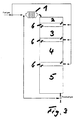
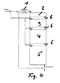
Figures 3 and4 should in particular illustrate that the number of fuel cells which form arespective stack - The
stacks adapter plate 6. Natural gas which is internally reformed in thestacks adapter plates 6 to thestacks - In this respect, an indirect internal reforming can take place with the flow supply shown in
Figure 3 in theadapter plates 6 and a direct internal reforming in the fuel cells of thestacks - There is the possibility with the flow management of the additionally supplied natural gas, as is shown in
Figure 4 , of being able to carry out a direct internal reforming in the fuel cells of thestacks - In the example shown in
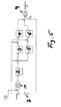
Figure 5 , which is not part of the invention, fuel gas formed in thereformer 1 is supplied to afirst stack 2. Tworespective stacks stacks stacks stacks reformer 1 with the help of thecompressor 7 and a regulable valve. In this example, residual gas can also be conducted through an afterburner 9.
Claims (5)
- A high-temperature fuel cell system which is operable with at least one hydrocarbon compound, wherein stacks 2, (3, 4, 5) are formed with individual fuel cells connected electrically in series, said stacks being sequentially flowed through by fuel gas containing hydrogen which flows into a first stack (2) of the system from a reformer (1) and methane or gas containing methane can be supplied via further connection lines sequentially in the direction of flow of the introduced fuel gas into further stacks (3, 4, 5) to the individual stack (3, 4, 5) for a direct internal reforming of at least one hydrocarbon compound to a fuel gas containing hydrogen at anodes of the fuel cells of the stack (3, 4, 5); and air can be supplied as an oxidation means at the cathode side to the individual fuel cells of the system,
wherein the number of fuel cells forming a stack (3, 4, 5) increases in the flow direction of the fuel gas through the system characterized in that the size of the anode surfaces of individual fuel cells increases in this direction. - A system in accordance with claim 1, characterized in that the reformer (1) is a steam reformer into which residual fuel gas discharged from the system can be returned.
- A system in accordance with claim 1, characterized in that the reformer (1) is made for a reforming by partial oxidation.
- A system in accordance with one of the preceding claims, characterized in that air can be supplied as an oxidation means via a separate connection line to each stack (3, 4, 5).
- A system in accordance with one of the preceding claims, characterized in that the volume flow of returned residual fuel gas can be regulated in dependence on the temperature and/or on the electrical power of the system.
Applications Claiming Priority (2)
| Application Number | Priority Date | Filing Date | Title |
|---|---|---|---|
| DE102009031774A DE102009031774B4 (en) | 2009-06-30 | 2009-06-30 | High-temperature fuel cell system |
| PCT/EP2010/003798 WO2011000499A1 (en) | 2009-06-30 | 2010-06-24 | High-temperature fuel cell system |
Publications (2)
| Publication Number | Publication Date |
|---|---|
| EP2449617A1 EP2449617A1 (en) | 2012-05-09 |
| EP2449617B1 true EP2449617B1 (en) | 2015-08-12 |
Family
ID=42697430
Family Applications (1)
| Application Number | Title | Priority Date | Filing Date |
|---|---|---|---|
| EP10728601.5A Not-in-force EP2449617B1 (en) | 2009-06-30 | 2010-06-24 | High-temperature fuel cell system |
Country Status (6)
| Country | Link |
|---|---|
| US (1) | US8512901B2 (en) |
| EP (1) | EP2449617B1 (en) |
| JP (2) | JP2012531719A (en) |
| KR (1) | KR20120092503A (en) |
| DE (1) | DE102009031774B4 (en) |
| WO (1) | WO2011000499A1 (en) |
Families Citing this family (23)
| Publication number | Priority date | Publication date | Assignee | Title |
|---|---|---|---|---|
| DE102011121691B4 (en) * | 2011-12-15 | 2015-07-23 | Fraunhofer-Gesellschaft zur Förderung der angewandten Forschung e.V. | A solid oxide fuel cell system and method for operating solid oxide fuel cells |
| JP5773931B2 (en) * | 2012-03-30 | 2015-09-02 | 東京瓦斯株式会社 | High temperature fuel cell system and operation method thereof |
| JP2013258004A (en) * | 2012-06-12 | 2013-12-26 | Tokyo Gas Co Ltd | High-temperature fuel cell system |
| US9847543B2 (en) | 2013-03-06 | 2017-12-19 | Fuelcell Energy, Inc. | Fuel cell system having biogas desulfurizer assembly with manganese oxide desulfurizer material |
| JP6061892B2 (en) * | 2014-04-04 | 2017-01-18 | 東京瓦斯株式会社 | Fuel cell power generation system |
| GB201406449D0 (en) * | 2014-04-10 | 2014-05-28 | Lg Fuel Cell Systems Inc | Fuel cell system with improved thermal management |
| DE102014219888A1 (en) * | 2014-10-01 | 2016-05-25 | Robert Bosch Gmbh | Fuel cell system and method for operating a fuel cell system with increased efficiency |
| US9502728B1 (en) | 2015-06-05 | 2016-11-22 | Fuelcell Energy, Inc. | High-efficiency molten carbonate fuel cell system with carbon dioxide capture assembly and method |
| CN107851819B (en) * | 2015-07-08 | 2018-12-11 | 日产自动车株式会社 | Fuel cell system |
| EP3349284B1 (en) * | 2015-09-09 | 2019-07-24 | Panasonic Intellectual Property Management Co., Ltd. | Fuel cell system |
| CN109314257B (en) | 2016-04-21 | 2021-10-19 | 燃料电池能有限公司 | Molten Carbonate Fuel Cell Anode Exhaust Aftertreatment for Carbon Dioxide Capture |
| JP6799078B2 (en) | 2016-04-29 | 2020-12-09 | フュエルセル エナジー, インコーポレイテッドFuelcell Energy, Inc. | Methaneization of anode exhaust gas to enhance carbon dioxide capture |
| AU2019388977B2 (en) | 2018-11-30 | 2025-01-30 | ExxonMobil Technology and Engineering Company | Flow field baffle for molten carbonate fuel cell cathode |
| WO2020112804A1 (en) | 2018-11-30 | 2020-06-04 | Exxonmobil Research And Engineering Company | Cathode collector structures for molten carbonate fuel cell |
| KR102610181B1 (en) | 2018-11-30 | 2023-12-04 | 퓨얼셀 에너지, 인크 | Modification of catalyst patterns for fuel cells operating with improved CO2 utilization |
| CN110767922A (en) * | 2019-10-21 | 2020-02-07 | 深圳市氢蓝时代动力科技有限公司 | Hydrogen fuel cell and engine capable of adjusting gas supply mode |
| CN110808387A (en) * | 2019-10-21 | 2020-02-18 | 深圳市氢蓝时代动力科技有限公司 | Gas supply method for hydrogen fuel cell, hydrogen fuel cell and engine |
| CN110828857A (en) * | 2019-10-21 | 2020-02-21 | 深圳市氢蓝时代动力科技有限公司 | A hydrogen fuel cell and engine that can improve the utilization rate of hydrogen |
| CN110718705A (en) * | 2019-10-21 | 2020-01-21 | 深圳市氢蓝时代动力科技有限公司 | A hydrogen fuel cell and engine |
| US12334607B2 (en) | 2019-11-26 | 2025-06-17 | ExxonMobil Technology and Engineering Company | Fuel cell assembly with external manifold for parallel flow |
| AU2019476338B2 (en) | 2019-11-26 | 2024-04-04 | ExxonMobil Technology and Engineering Company | Fuel cell module assembly and systems using same |
| WO2021181249A1 (en) | 2020-03-11 | 2021-09-16 | Fuelcell Energy, Inc. | Steam methane reforming unit for carbon capture |
| WO2021186879A1 (en) * | 2020-03-16 | 2021-09-23 | パナソニックIpマネジメント株式会社 | Fuel cell system |
Citations (1)
| Publication number | Priority date | Publication date | Assignee | Title |
|---|---|---|---|---|
| JP2004247268A (en) * | 2003-02-17 | 2004-09-02 | Tokyo Gas Co Ltd | Solid oxide fuel cell system and operating method thereof |
Family Cites Families (27)
| Publication number | Priority date | Publication date | Assignee | Title |
|---|---|---|---|---|
| US4024A (en) * | 1845-05-01 | Cutting and crushing corn-fodder | ||
| US9009A (en) * | 1852-06-08 | Bat-trap | ||
| US4023A (en) * | 1845-05-01 | Hijbst | ||
| JPS62133673A (en) * | 1985-12-06 | 1987-06-16 | Mitsubishi Electric Corp | Fuel cell device |
| JP2791568B2 (en) | 1988-12-22 | 1998-08-27 | 日揮株式会社 | Fuel cell power generation system |
| JP3006200B2 (en) * | 1991-08-09 | 2000-02-07 | 石川島播磨重工業株式会社 | Molten carbonate fuel cell power generation method |
| JPH0547395A (en) * | 1991-08-16 | 1993-02-26 | Chubu Electric Power Co Inc | Fuel cell power generator |
| JPH05335029A (en) * | 1992-06-01 | 1993-12-17 | Hitachi Ltd | Fuel cell power generation system |
| US5413878A (en) * | 1993-10-28 | 1995-05-09 | The United States Of America As Represented By The Department Of Energy | System and method for networking electrochemical devices |
| NL1004513C2 (en) * | 1996-11-13 | 1998-05-29 | Stichting Energie | Series connected fuel cell system. |
| JPH117971A (en) * | 1997-06-18 | 1999-01-12 | Mitsubishi Electric Corp | Medium and large capacity fuel cell power generator |
| JP3917838B2 (en) * | 2001-10-12 | 2007-05-23 | 三菱重工業株式会社 | Fuel cell system and combined power generation system |
| JP2003243000A (en) * | 2002-02-19 | 2003-08-29 | Aisin Seiki Co Ltd | Solid oxide fuel cell system and control method thereof |
| JP2004063341A (en) * | 2002-07-30 | 2004-02-26 | Nissan Motor Co Ltd | Fuel cell system |
| JP4329345B2 (en) * | 2003-01-21 | 2009-09-09 | 三菱マテリアル株式会社 | Internal reforming fuel cell |
| US7503948B2 (en) | 2003-05-23 | 2009-03-17 | Exxonmobil Research And Engineering Company | Solid oxide fuel cell systems having temperature swing reforming |
| US7674538B2 (en) * | 2004-03-04 | 2010-03-09 | Delphi Technologies, Inc. | Apparatus and method for high efficiency operation of a high temperature fuel cell system |
| JP2005317489A (en) * | 2004-03-29 | 2005-11-10 | Osaka Gas Co Ltd | Solid oxide fuel cell system |
| US7510793B2 (en) * | 2004-08-05 | 2009-03-31 | Rolls-Royce Fuel Cell Systems (Us) Inc. | Post-reformer treatment of reformate gas |
| US7615299B2 (en) | 2005-01-28 | 2009-11-10 | Delphi Technologies, Inc. | Method and apparatus for thermal, mechanical, and electrical optimization of a solid-oxide fuel cell stack |
| US8142943B2 (en) | 2005-11-16 | 2012-03-27 | Bloom Energy Corporation | Solid oxide fuel cell column temperature equalization by internal reforming and fuel cascading |
| US8097374B2 (en) * | 2005-11-16 | 2012-01-17 | Bloom Energy Corporation | System and method for providing reformed fuel to cascaded fuel cell stacks |
| JP4887048B2 (en) | 2006-01-30 | 2012-02-29 | アイシン精機株式会社 | Fuel cell starting method and fuel cell system |
| US8053139B2 (en) * | 2006-03-31 | 2011-11-08 | Corning Incorporated | SOFC thermal management via direct injection |
| US8067122B2 (en) | 2006-04-19 | 2011-11-29 | Panasonic Corporation | Fuel cell system |
| JP2009117054A (en) * | 2007-11-01 | 2009-05-28 | Tokyo Gas Co Ltd | Power generation method and system using high-temperature fuel cell |
| JP2010038051A (en) | 2008-08-06 | 2010-02-18 | Denso Corp | Torque control device for onboard power generator |
-
2009
- 2009-06-30 DE DE102009031774A patent/DE102009031774B4/en active Active
-
2010
- 2010-06-24 US US13/381,568 patent/US8512901B2/en active Active
- 2010-06-24 KR KR1020117031252A patent/KR20120092503A/en not_active Withdrawn
- 2010-06-24 JP JP2012518041A patent/JP2012531719A/en active Pending
- 2010-06-24 EP EP10728601.5A patent/EP2449617B1/en not_active Not-in-force
- 2010-06-24 WO PCT/EP2010/003798 patent/WO2011000499A1/en not_active Ceased
-
2015
- 2015-03-03 JP JP2015040860A patent/JP2015099803A/en active Pending
Patent Citations (1)
| Publication number | Priority date | Publication date | Assignee | Title |
|---|---|---|---|---|
| JP2004247268A (en) * | 2003-02-17 | 2004-09-02 | Tokyo Gas Co Ltd | Solid oxide fuel cell system and operating method thereof |
Also Published As
| Publication number | Publication date |
|---|---|
| US8512901B2 (en) | 2013-08-20 |
| DE102009031774A1 (en) | 2011-01-05 |
| EP2449617A1 (en) | 2012-05-09 |
| JP2015099803A (en) | 2015-05-28 |
| KR20120092503A (en) | 2012-08-21 |
| WO2011000499A1 (en) | 2011-01-06 |
| DE102009031774B4 (en) | 2012-02-02 |
| JP2012531719A (en) | 2012-12-10 |
| US20120178005A1 (en) | 2012-07-12 |
Similar Documents
| Publication | Publication Date | Title |
|---|---|---|
| US8512901B2 (en) | High-temperature fuel cell system | |
| US8142943B2 (en) | Solid oxide fuel cell column temperature equalization by internal reforming and fuel cascading | |
| US10608271B2 (en) | SOFC-based system for generating electricity with closed-loop circulation of carbonated species | |
| US6531243B2 (en) | Solid oxide fuel operating with an excess of fuel | |
| EP2331247B1 (en) | Reformer | |
| EP2331246B1 (en) | Desulfurizer | |
| JP7286769B2 (en) | Cathode Current Collector Structure of Molten Carbonate Fuel Cell | |
| JP3781942B2 (en) | Solid oxide fuel cell system | |
| CA2817108C (en) | A solid oxide fuel cell system and a method of operating a solid oxide fuel cell system | |
| US8097374B2 (en) | System and method for providing reformed fuel to cascaded fuel cell stacks | |
| WO2020112895A1 (en) | Reforming catalyst pattern for fuel cell operated with enhanced co2 utilization | |
| CN100377402C (en) | Battery stack with improved cooling structure and fuel cell system thereof | |
| US7879504B2 (en) | Fuel cell stack having improved cooling structure | |
| JP4956946B2 (en) | Fuel cell | |
| KR20200086697A (en) | Hydrogen generation using a fuel cell system with REP | |
| JP2024508170A (en) | fuel cell system | |
| CN118156576B (en) | Fuel cell system and control method thereof | |
| US11196063B2 (en) | System and method for solid oxide fuel cells with staged fuel supply | |
| JP4706191B2 (en) | Solid oxide fuel cell | |
| KR100658289B1 (en) | Separator having heating gas inlet and fuel cell system having same | |
| US20240234754A1 (en) | Direct and homogeneous internal reforming solid oxide fuel cell system | |
| EP3888165A1 (en) | Reforming catalyst pattern for fuel cell operated with enhanced co2 utilization | |
| KR20070075041A (en) | Fuel cell system with heat supply plate |
Legal Events
| Date | Code | Title | Description |
|---|---|---|---|
| PUAI | Public reference made under article 153(3) epc to a published international application that has entered the european phase |
Free format text: ORIGINAL CODE: 0009012 |
|
| 17P | Request for examination filed |
Effective date: 20120117 |
|
| AK | Designated contracting states |
Kind code of ref document: A1 Designated state(s): AL AT BE BG CH CY CZ DE DK EE ES FI FR GB GR HR HU IE IS IT LI LT LU LV MC MK MT NL NO PL PT RO SE SI SK SM TR |
|
| DAX | Request for extension of the european patent (deleted) | ||
| 17Q | First examination report despatched |
Effective date: 20130904 |
|
| REG | Reference to a national code |
Ref country code: DE Ref legal event code: R079 Free format text: PREVIOUS MAIN CLASS: H01M0008060000 Ipc: C01B0003380000 |
|
| RIC1 | Information provided on ipc code assigned before grant |
Ipc: H01M 8/12 20060101ALN20141128BHEP Ipc: H01M 8/06 20060101ALI20141128BHEP Ipc: C01B 3/38 20060101AFI20141128BHEP Ipc: H01M 8/04 20060101ALI20141128BHEP |
|
| GRAP | Despatch of communication of intention to grant a patent |
Free format text: ORIGINAL CODE: EPIDOSNIGR1 |
|
| RIC1 | Information provided on ipc code assigned before grant |
Ipc: H01M 8/12 20060101ALN20141218BHEP Ipc: H01M 8/06 20060101ALI20141218BHEP Ipc: H01M 8/04 20060101ALI20141218BHEP Ipc: C01B 3/38 20060101AFI20141218BHEP |
|
| INTG | Intention to grant announced |
Effective date: 20150114 |
|
| GRAS | Grant fee paid |
Free format text: ORIGINAL CODE: EPIDOSNIGR3 |
|
| RBV | Designated contracting states (corrected) |
Designated state(s): AL AT BE BG CH CY CZ DK EE ES FI FR GB GR HR HU IE IS IT LI LT LU LV MC MK MT NL NO PL PT RO SE SI SK SM TR |
|
| REG | Reference to a national code |
Ref country code: DE Ref legal event code: R108 |
|
| GRAA | (expected) grant |
Free format text: ORIGINAL CODE: 0009210 |
|
| AK | Designated contracting states |
Kind code of ref document: B1 Designated state(s): AL AT BE BG CH CY CZ DK EE ES FI FR GB GR HR HU IE IS IT LI LT LU LV MC MK MT NL NO PL PT RO SE SI SK SM TR |
|
| REG | Reference to a national code |
Ref country code: GB Ref legal event code: FG4D |
|
| REG | Reference to a national code |
Ref country code: CH Ref legal event code: EP |
|
| REG | Reference to a national code |
Ref country code: AT Ref legal event code: REF Ref document number: 741967 Country of ref document: AT Kind code of ref document: T Effective date: 20150815 |
|
| REG | Reference to a national code |
Ref country code: IE Ref legal event code: FG4D |
|
| REG | Reference to a national code |
Ref country code: LT Ref legal event code: MG4D |
|
| REG | Reference to a national code |
Ref country code: AT Ref legal event code: MK05 Ref document number: 741967 Country of ref document: AT Kind code of ref document: T Effective date: 20150812 |
|
| REG | Reference to a national code |
Ref country code: NL Ref legal event code: MP Effective date: 20150812 |
|
| PG25 | Lapsed in a contracting state [announced via postgrant information from national office to epo] |
Ref country code: LT Free format text: LAPSE BECAUSE OF FAILURE TO SUBMIT A TRANSLATION OF THE DESCRIPTION OR TO PAY THE FEE WITHIN THE PRESCRIBED TIME-LIMIT Effective date: 20150812 Ref country code: NO Free format text: LAPSE BECAUSE OF FAILURE TO SUBMIT A TRANSLATION OF THE DESCRIPTION OR TO PAY THE FEE WITHIN THE PRESCRIBED TIME-LIMIT Effective date: 20151112 Ref country code: LV Free format text: LAPSE BECAUSE OF FAILURE TO SUBMIT A TRANSLATION OF THE DESCRIPTION OR TO PAY THE FEE WITHIN THE PRESCRIBED TIME-LIMIT Effective date: 20150812 Ref country code: GR Free format text: LAPSE BECAUSE OF FAILURE TO SUBMIT A TRANSLATION OF THE DESCRIPTION OR TO PAY THE FEE WITHIN THE PRESCRIBED TIME-LIMIT Effective date: 20151113 Ref country code: FI Free format text: LAPSE BECAUSE OF FAILURE TO SUBMIT A TRANSLATION OF THE DESCRIPTION OR TO PAY THE FEE WITHIN THE PRESCRIBED TIME-LIMIT Effective date: 20150812 |
|
| PG25 | Lapsed in a contracting state [announced via postgrant information from national office to epo] |
Ref country code: PL Free format text: LAPSE BECAUSE OF FAILURE TO SUBMIT A TRANSLATION OF THE DESCRIPTION OR TO PAY THE FEE WITHIN THE PRESCRIBED TIME-LIMIT Effective date: 20150812 Ref country code: PT Free format text: LAPSE BECAUSE OF FAILURE TO SUBMIT A TRANSLATION OF THE DESCRIPTION OR TO PAY THE FEE WITHIN THE PRESCRIBED TIME-LIMIT Effective date: 20151214 Ref country code: AT Free format text: LAPSE BECAUSE OF FAILURE TO SUBMIT A TRANSLATION OF THE DESCRIPTION OR TO PAY THE FEE WITHIN THE PRESCRIBED TIME-LIMIT Effective date: 20150812 Ref country code: IS Free format text: LAPSE BECAUSE OF FAILURE TO SUBMIT A TRANSLATION OF THE DESCRIPTION OR TO PAY THE FEE WITHIN THE PRESCRIBED TIME-LIMIT Effective date: 20151212 Ref country code: SE Free format text: LAPSE BECAUSE OF FAILURE TO SUBMIT A TRANSLATION OF THE DESCRIPTION OR TO PAY THE FEE WITHIN THE PRESCRIBED TIME-LIMIT Effective date: 20150812 Ref country code: ES Free format text: LAPSE BECAUSE OF FAILURE TO SUBMIT A TRANSLATION OF THE DESCRIPTION OR TO PAY THE FEE WITHIN THE PRESCRIBED TIME-LIMIT Effective date: 20150812 Ref country code: HR Free format text: LAPSE BECAUSE OF FAILURE TO SUBMIT A TRANSLATION OF THE DESCRIPTION OR TO PAY THE FEE WITHIN THE PRESCRIBED TIME-LIMIT Effective date: 20150812 |
|
| PG25 | Lapsed in a contracting state [announced via postgrant information from national office to epo] |
Ref country code: NL Free format text: LAPSE BECAUSE OF FAILURE TO SUBMIT A TRANSLATION OF THE DESCRIPTION OR TO PAY THE FEE WITHIN THE PRESCRIBED TIME-LIMIT Effective date: 20150812 |
|
| PG25 | Lapsed in a contracting state [announced via postgrant information from national office to epo] |
Ref country code: CZ Free format text: LAPSE BECAUSE OF FAILURE TO SUBMIT A TRANSLATION OF THE DESCRIPTION OR TO PAY THE FEE WITHIN THE PRESCRIBED TIME-LIMIT Effective date: 20150812 Ref country code: SK Free format text: LAPSE BECAUSE OF FAILURE TO SUBMIT A TRANSLATION OF THE DESCRIPTION OR TO PAY THE FEE WITHIN THE PRESCRIBED TIME-LIMIT Effective date: 20150812 Ref country code: EE Free format text: LAPSE BECAUSE OF FAILURE TO SUBMIT A TRANSLATION OF THE DESCRIPTION OR TO PAY THE FEE WITHIN THE PRESCRIBED TIME-LIMIT Effective date: 20150812 Ref country code: DK Free format text: LAPSE BECAUSE OF FAILURE TO SUBMIT A TRANSLATION OF THE DESCRIPTION OR TO PAY THE FEE WITHIN THE PRESCRIBED TIME-LIMIT Effective date: 20150812 |
|
| PG25 | Lapsed in a contracting state [announced via postgrant information from national office to epo] |
Ref country code: RO Free format text: LAPSE BECAUSE OF FAILURE TO SUBMIT A TRANSLATION OF THE DESCRIPTION OR TO PAY THE FEE WITHIN THE PRESCRIBED TIME-LIMIT Effective date: 20150812 |
|
| PLBE | No opposition filed within time limit |
Free format text: ORIGINAL CODE: 0009261 |
|
| STAA | Information on the status of an ep patent application or granted ep patent |
Free format text: STATUS: NO OPPOSITION FILED WITHIN TIME LIMIT |
|
| 26N | No opposition filed |
Effective date: 20160513 |
|
| PG25 | Lapsed in a contracting state [announced via postgrant information from national office to epo] |
Ref country code: SI Free format text: LAPSE BECAUSE OF FAILURE TO SUBMIT A TRANSLATION OF THE DESCRIPTION OR TO PAY THE FEE WITHIN THE PRESCRIBED TIME-LIMIT Effective date: 20150812 |
|
| PG25 | Lapsed in a contracting state [announced via postgrant information from national office to epo] |
Ref country code: BE Free format text: LAPSE BECAUSE OF FAILURE TO SUBMIT A TRANSLATION OF THE DESCRIPTION OR TO PAY THE FEE WITHIN THE PRESCRIBED TIME-LIMIT Effective date: 20150812 |
|
| PG25 | Lapsed in a contracting state [announced via postgrant information from national office to epo] |
Ref country code: MC Free format text: LAPSE BECAUSE OF FAILURE TO SUBMIT A TRANSLATION OF THE DESCRIPTION OR TO PAY THE FEE WITHIN THE PRESCRIBED TIME-LIMIT Effective date: 20150812 |
|
| REG | Reference to a national code |
Ref country code: CH Ref legal event code: PL |
|
| GBPC | Gb: european patent ceased through non-payment of renewal fee |
Effective date: 20160624 |
|
| REG | Reference to a national code |
Ref country code: IE Ref legal event code: MM4A |
|
| REG | Reference to a national code |
Ref country code: FR Ref legal event code: ST Effective date: 20170228 |
|
| PG25 | Lapsed in a contracting state [announced via postgrant information from national office to epo] |
Ref country code: LI Free format text: LAPSE BECAUSE OF NON-PAYMENT OF DUE FEES Effective date: 20160630 Ref country code: CH Free format text: LAPSE BECAUSE OF NON-PAYMENT OF DUE FEES Effective date: 20160630 Ref country code: FR Free format text: LAPSE BECAUSE OF NON-PAYMENT OF DUE FEES Effective date: 20160630 |
|
| PG25 | Lapsed in a contracting state [announced via postgrant information from national office to epo] |
Ref country code: GB Free format text: LAPSE BECAUSE OF NON-PAYMENT OF DUE FEES Effective date: 20160624 Ref country code: IE Free format text: LAPSE BECAUSE OF NON-PAYMENT OF DUE FEES Effective date: 20160624 |
|
| PG25 | Lapsed in a contracting state [announced via postgrant information from national office to epo] |
Ref country code: HU Free format text: LAPSE BECAUSE OF FAILURE TO SUBMIT A TRANSLATION OF THE DESCRIPTION OR TO PAY THE FEE WITHIN THE PRESCRIBED TIME-LIMIT; INVALID AB INITIO Effective date: 20100624 Ref country code: CY Free format text: LAPSE BECAUSE OF FAILURE TO SUBMIT A TRANSLATION OF THE DESCRIPTION OR TO PAY THE FEE WITHIN THE PRESCRIBED TIME-LIMIT Effective date: 20150812 Ref country code: SM Free format text: LAPSE BECAUSE OF FAILURE TO SUBMIT A TRANSLATION OF THE DESCRIPTION OR TO PAY THE FEE WITHIN THE PRESCRIBED TIME-LIMIT Effective date: 20150812 |
|
| PG25 | Lapsed in a contracting state [announced via postgrant information from national office to epo] |
Ref country code: MK Free format text: LAPSE BECAUSE OF FAILURE TO SUBMIT A TRANSLATION OF THE DESCRIPTION OR TO PAY THE FEE WITHIN THE PRESCRIBED TIME-LIMIT Effective date: 20150812 Ref country code: TR Free format text: LAPSE BECAUSE OF FAILURE TO SUBMIT A TRANSLATION OF THE DESCRIPTION OR TO PAY THE FEE WITHIN THE PRESCRIBED TIME-LIMIT Effective date: 20150812 Ref country code: LU Free format text: LAPSE BECAUSE OF NON-PAYMENT OF DUE FEES Effective date: 20160624 Ref country code: MT Free format text: LAPSE BECAUSE OF NON-PAYMENT OF DUE FEES Effective date: 20160630 |
|
| PG25 | Lapsed in a contracting state [announced via postgrant information from national office to epo] |
Ref country code: BG Free format text: LAPSE BECAUSE OF FAILURE TO SUBMIT A TRANSLATION OF THE DESCRIPTION OR TO PAY THE FEE WITHIN THE PRESCRIBED TIME-LIMIT Effective date: 20150812 |
|
| PG25 | Lapsed in a contracting state [announced via postgrant information from national office to epo] |
Ref country code: AL Free format text: LAPSE BECAUSE OF FAILURE TO SUBMIT A TRANSLATION OF THE DESCRIPTION OR TO PAY THE FEE WITHIN THE PRESCRIBED TIME-LIMIT Effective date: 20150812 |
|
| PGFP | Annual fee paid to national office [announced via postgrant information from national office to epo] |
Ref country code: IT Payment date: 20180622 Year of fee payment: 9 |
|
| PG25 | Lapsed in a contracting state [announced via postgrant information from national office to epo] |
Ref country code: IT Free format text: LAPSE BECAUSE OF NON-PAYMENT OF DUE FEES Effective date: 20190624 |