EP2449448B1 - Control device comprising a moveable upper panel and arms for actuating a switch - Google Patents
Control device comprising a moveable upper panel and arms for actuating a switch Download PDFInfo
- Publication number
- EP2449448B1 EP2449448B1 EP10732683.7A EP10732683A EP2449448B1 EP 2449448 B1 EP2449448 B1 EP 2449448B1 EP 10732683 A EP10732683 A EP 10732683A EP 2449448 B1 EP2449448 B1 EP 2449448B1
- Authority
- EP
- European Patent Office
- Prior art keywords
- upper panel
- switch
- arms
- armature
- arm
- Prior art date
- Legal status (The legal status is an assumption and is not a legal conclusion. Google has not performed a legal analysis and makes no representation as to the accuracy of the status listed.)
- Active
Links
- 230000000694 effects Effects 0.000 claims description 14
- 230000002093 peripheral effect Effects 0.000 claims description 10
- 239000002184 metal Substances 0.000 description 8
- 239000000758 substrate Substances 0.000 description 6
- 239000000463 material Substances 0.000 description 5
- 230000000295 complement effect Effects 0.000 description 2
- 230000005489 elastic deformation Effects 0.000 description 2
- 230000005484 gravity Effects 0.000 description 2
- 238000012360 testing method Methods 0.000 description 2
- 238000005452 bending Methods 0.000 description 1
- 238000010276 construction Methods 0.000 description 1
- 230000035807 sensation Effects 0.000 description 1
Images


Classifications
-
- G—PHYSICS
- G06—COMPUTING; CALCULATING OR COUNTING
- G06F—ELECTRIC DIGITAL DATA PROCESSING
- G06F3/00—Input arrangements for transferring data to be processed into a form capable of being handled by the computer; Output arrangements for transferring data from processing unit to output unit, e.g. interface arrangements
- G06F3/01—Input arrangements or combined input and output arrangements for interaction between user and computer
- G06F3/03—Arrangements for converting the position or the displacement of a member into a coded form
- G06F3/033—Pointing devices displaced or positioned by the user, e.g. mice, trackballs, pens or joysticks; Accessories therefor
- G06F3/0354—Pointing devices displaced or positioned by the user, e.g. mice, trackballs, pens or joysticks; Accessories therefor with detection of 2D relative movements between the device, or an operating part thereof, and a plane or surface, e.g. 2D mice, trackballs, pens or pucks
- G06F3/03547—Touch pads, in which fingers can move on a surface
-
- G—PHYSICS
- G06—COMPUTING; CALCULATING OR COUNTING
- G06F—ELECTRIC DIGITAL DATA PROCESSING
- G06F3/00—Input arrangements for transferring data to be processed into a form capable of being handled by the computer; Output arrangements for transferring data from processing unit to output unit, e.g. interface arrangements
- G06F3/01—Input arrangements or combined input and output arrangements for interaction between user and computer
- G06F3/03—Arrangements for converting the position or the displacement of a member into a coded form
- G06F3/041—Digitisers, e.g. for touch screens or touch pads, characterised by the transducing means
-
- H—ELECTRICITY
- H01—ELECTRIC ELEMENTS
- H01H—ELECTRIC SWITCHES; RELAYS; SELECTORS; EMERGENCY PROTECTIVE DEVICES
- H01H3/00—Mechanisms for operating contacts
- H01H3/02—Operating parts, i.e. for operating driving mechanism by a mechanical force external to the switch
- H01H3/12—Push-buttons
- H01H3/122—Push-buttons with enlarged actuating area, e.g. of the elongated bar-type; Stabilising means therefor
- H01H3/125—Push-buttons with enlarged actuating area, e.g. of the elongated bar-type; Stabilising means therefor using a scissor mechanism as stabiliser
-
- H—ELECTRICITY
- H01—ELECTRIC ELEMENTS
- H01H—ELECTRIC SWITCHES; RELAYS; SELECTORS; EMERGENCY PROTECTIVE DEVICES
- H01H3/00—Mechanisms for operating contacts
- H01H3/02—Operating parts, i.e. for operating driving mechanism by a mechanical force external to the switch
- H01H3/16—Operating parts, i.e. for operating driving mechanism by a mechanical force external to the switch adapted for actuation at a limit or other predetermined position in the path of a body, the relative movement of switch and body being primarily for a purpose other than the actuation of the switch, e.g. for a door switch, a limit switch, a floor-levelling switch of a lift
Definitions
- the invention provides a device for controlling an electronic apparatus, comprising a moveable upper panel on which at least one control action is exerted.
- the invention provides a device for controlling an electronic apparatus, comprising a generally flat and horizontal upper panel on an upper face of which a control member is capable of exerting a control action, consisting of a compressive force oriented generally downwards, a lower armature of a support with respect to which armature the upper panel can move in a generally vertically downward movement under the effect of the control action, a switch which is carried by the armature and which can be actuated under the effect of the control action in order to produce a signal for controlling the electronic apparatus, and at least two arms for actuating the switch.
- a control action consisting of a compressive force oriented generally downwards
- a lower armature of a support with respect to which armature the upper panel can move in a generally vertically downward movement under the effect of the control action
- a switch which is carried by the armature and which can be actuated under the effect of the control action in order to produce a signal for controlling the electronic apparatus, and at least two arms for actuating the switch.
- the control device is designed in such a way that, under the effect of the control action, the upper panel moves downwards in a movement consisting generally of a vertical translation and so as to actuate the switch via the actuating arms.
- the actuating arms cooperate with the upper panel and with the lower armature in order to keep the upper panel substantially parallel to its horizontal plane when the control action is exerted.
- the switch is actuated by a single actuating arm under the effect of the control action, thereby making the system unbalanced depending on whether the control action is exerted on the upper panel at a point positioned close to the position of the switch or at a point away from said switch.
- each arm is linked to the upper panel, to the lower armature or to the other arms via articulations for which a certain operating play is necessary in order to allow relative movement of the components.
- This embodiment makes it possible to avoid the problems resulting from the operating plays mentioned here above.
- each arm is connected to the upper panel at a point which is positioned horizontally in a position which is intermediate between the centre of the upper panel and the peripheral edge of the upper panel.
- the upper panel when the point of application of the control action on the upper panel is positioned close to the peripheral edge of the upper panel, the upper panel then tilts about an actuating arm.
- Document US2008/0185279 describes an improved press key structure capable of providing a uniform support to its keycap for preventing the same from slanting by pressing.
- the structure comprises: a keycap, configured with a bottom surface; a substrate, disposed beneath the keycap; an elastic member 35 disposed on the substrate, which, in conjunction with a conducting plate arranged at its bottom and a circuit board arranged beneath the substrate, provides a switch; and first and second movable panels disposed in a space between the substrate and the keycap.
- the panels are pivotally coupled with each other by the use of a flange and a groove formed respectively on the neighbouring edges of the panels.
- the panels are also pivotally coupled to the substrate by support axes arranged at the center of the each panel and support seats arranged on the substrate.
- the panels are pivotally coupled to the keycap by the use of pivot axes on the two edges of the panels that are away from each other and pivot seats formed at the bottom surface of the keycap. This arrangement enables the keycap to descend smoothly without tilting even when an off-center force is applied to it.
- the object of the invention is to provide an alternate structure for a device for controlling an electronic apparatus permitting the upper panel to be kept parallel to its horizontal plane, irrespective of the position of the point of application of the control action.
- the invention provides a device for controlling an electronic apparatus, comprising a generally flat and horizontal upper panel on an upper face of which a control member is capable of exerting a control action, consisting of a compressive force oriented generally downwards, a lower armature of a support with respect to which armature the upper panel can move in a generally vertically downward movement under the effect of the control action, a switch which is carried by the armature and which can be actuated under the effect of the control action in order to produce a signal for controlling the electronic apparatus, and at least two arms for actuating the switch, each arm comprising a first end which bears vertically upwards on a lower face of the upper panel, a second end which bears on, or presses against, the switch, and an intermediate portion which bears vertically downwards on an upper face of the armature and around which portion each arm can pivot about a horizontal geometric pivot axis, in which the arms cooperate with the upper panel and the armature in order to keep the upper panel parallel to a horizontal plane during its vertical
- the invention also provides a device for controlling an electronic apparatus, comprising a generally flat and horizontal upper panel on an upper face of which a control member is capable of exerting a control action, consisting of a compressive force oriented generally downwards, a lower armature of a support with respect to which armature the upper panel can move in a generally vertically downward movement under the effect of the control action, a switch which is carried by the upper panel and can be actuated under the effect of the control action in order to produce a signal for controlling the electronic apparatus, and at least two arms for actuating the switch, each arm comprising a first end which bears vertically downwards on an upper face of the armature, a second end which bears on the switch, and an intermediate portion which bears vertically upwards on a lower face of the upper panel and around which intermediate portion each arm can pivot about a horizontal geometric pivot axis, in which device the arms cooperate with the upper panel and the armature in order to keep the upper panel parallel to a horizontal plane during its vertical movement with respect to the
- a device 20 for controlling an electronic apparatus such as for example a computer, a PDA (Personal Digital Assistant) or a "smart phone", which combines the features of a PDA with those of a digital telephone.
- PDA Personal Digital Assistant
- a "smart phone” which combines the features of a PDA with those of a digital telephone.
- the control device 20 comprises an upper panel 22 on which a user acts in order to control the electronic apparatus.
- the upper panel 22 consists of a flat element, which here is horizontal and of rectangular shape, the long sides of which are parallel to the longitudinal direction "L".
- the operation of actuating the control device 20 consists in exerting an action, hereafter called the "control action", on the upper face 22s of the upper panel 22 via a pointing element 24.
- This pointing element 24 is for example a stylus or a finger of the user.
- the control action consists of a compressive force mainly oriented vertically downwards, which is exerted by the pointing element at a point of contact "P" between one end of the pointing element 24 and the upper face 22s of the upper panel 22.
- the upper panel 22 consists only of a plate, for example made of a rigid plastic.
- the upper panel 22 includes means for locating the geometrical position of the contact point "P" on the upper face 22s of the upper panel 22.
- the control device 20 is then of the "touch pad” type, used for example for a portable computer.
- the upper panel 22 is then a component usually called a "touch pad”.
- the upper panel 22 includes, in addition to the locating means, information display means, for example a display screen, in order to permit the user to see information relating to the electronic apparatus, and/or information associated with the manipulations that the user performs on the upper panel 22.
- information display means for example a display screen
- the upper panel 22 is then a component usually called a "touch screen”.
- the control device 20 is intended to be mounted in the electronic apparatus in a manner such that the upper face 22s of the upper panel 22 is flush with a covering element or casing of the electronic apparatus.
- Each edge 38 of the upper panel 22 has a peripheral rim 100 which is positioned vertically set back with respect to the upper face 22s of the upper panel 22 and is intended to be held beneath the covering element.
- the rim 100 of the upper panel 22 cooperates with the covering element so that the upper panel 22 butts against the covering element in a high, rest position and for positioning the upper panel 22 horizontally and transversely with respect to the covering element.
- the control device 20 also includes a lower armature 26 by means of which the control device 20 is assembled inside the electronic apparatus.
- the armature 26 is shown in Figures 8A et seq. in the form of a flat plate and consists for example of a so-called "component-carrying" support plate on which electronic components and electronic circuits are placed.
- the armature 26 consists of a frame or framework made of sheet metal, which permits the control device 20 to be mounted and assembled on a support component of the electronic apparatus, for example on a component-carrying support plate.
- the upper panel 22 is mounted so as to move with respect to the armature 26 in a vertically downward movement when a control action is exerted on the upper face 22s of the upper panel 22.
- the upper panel 22 moves in the opposite direction, i.e. it undergoes a vertically upward movement with respect to the armature 26.
- the control device 20 includes a switch 28, or switching interrupter 28, that can be actuated when the upper panel 22 moves downwards under the effect of the control action, generating, as a result, a signal for controlling the electronic apparatus.
- the switch 28 may be of any known type.
- the compressive force exerted on the upper panel 22 is transmitted to the switch 28 in order for the switch 28 to be actuated under the effect of the control action.
- the switch 28 is capable of generating the control signal when it is submitted to a compressive force greater than a predetermined value.
- the switch 28 makes it possible to detect any control action consisting in exerting a pressure, greater than the predetermined threshold value, on the upper face 22s of the upper panel 22.
- the switch 28 when the pressure of the control action is below said threshold value, the switch 28 constitutes an abutment, or stop, for the upper panel 22 at a certain vertical (height) position with respect to the armature 26, preventing the upper panel 22 from moving downwards with respect to the armature. In this position, the switch 28 is not actuated, and therefore the control signal is not generated.
- the switch 28 is able to change state when the pressure of the control action exceeds said threshold value.
- the switch 28 therefore no longer forms an abutment for the upper panel 22, thus enabling the upper panel 22 to move downwards as far as a position called a position for actuating the switch 28.
- the control signal is then generated when the switch 28 changes state.
- a tactile sensation is also perceived by the user, via the pointing element 24, when the switch 28 changes state, especially since the user feels a rapid change in the resistance to the movement of the upper panel 22, in the manner of a "click" of a pushbutton.
- the user is thus informed by touch that the control action has been exerted on the control device 20.
- the control device 20 also has arms 30 for actuating the switch 28, which are positioned vertically globally between a horizontal lower face 22i of the upper panel 22 and, opposite, an upper face 26s of the armature 26.
- each arm bears on the switch 28 and each arm cooperates with the upper panel 22 and with the armature 26 in order to actuate the switch 28 when a control action is exerted on the upper face 22s of the upper panel 22.
- actuating arms 30 cooperate with the upper panel 22 and with the armature 26 in order to keep the upper panel 22 parallel to a horizontal plane, when the upper panel 22 moves vertically with respect to the armature 26.
- FIGS 8A to 15B show a first example of the control device in which the switch 28 is carried by the armature 26.
- each arm has a first end 32 which bears vertically upwards on the lower face 22i of the upper panel 22, a second end 34 which bears on the switch 28, and an intermediate portion 36 which bears vertically downwards against the upper face 26s of the armature 26.
- Each arm 30 also has straight portions connecting the intermediate portion 36 to the first end 32 and to the second end 34. These straight portions are relatively rigid so as to deform to a limited extent when the control device 20 is actuated.
- the first ends 32 of the arms 30 are positioned with respect to the upper panel 22 so that they are positioned respectively at the vertices of a polygon, each of which corresponds to a point where the first end 32 of an arm 30 bears on the lower face 22i of the upper panel 22.
- each arm 30 is positioned horizontally proximal to the peripheral edge 38 of the upper panel 22, so that the area of the polygon is as large as possible.
- each arm 30 bears on the upper face 26s of the armature 26 in such a way that the arm 30 can pivot with respect to the armature 26 about a horizontal pivot axis A, located in this intermediate portion 36.
- FIGS 8A and 8B show a first embodiment of this example, in which the control device 20 has two arms 30 placed between the upper panel 22 and the armature 26 for actuating the switch 28.
- the switch 28 is actuated directly by the second end 34 of each arm 30.
- the switch 28 is positioned horizontally globally at the centre of the upper panel 22.
- the two arms 30 are placed horizontally, on each side of the switch 28, that is to say they are here positioned horizontally, symmetrically with respect to the switch 28.
- each arm 30 consists of a plate, for example made of sheet metal, which has been cut, bent and stamped so as to define bearing and pivoting points at the first end 32, at the second end 34 and at the intermediate portion 36.
- each arm 30 is positioned proximal to a longitudinal edge 38 of the upper panel 22.
- each arm 30 bears on the lower face 22i of the upper panel 22 at two points positioned at the corners of the upper panel 22. These two bearing points are also aligned transversely.
- each arm 30 is positioned longitudinally at a distance intermediate between the first end 32 and the second end 34 of the arm 30.
- the intermediate portion 36 bears on the upper face 26s of the armature 26 at two points which are aligned transversely and which define the geometric pivot axis of the arm 30.
- this axis is here parallel to the transverse orientation "T".
- each arm is positioned horizontally in line with the switch 28, that is to say at the centre of the upper panel 22.
- the arms 30 pivot in such a way that each second end 34 moves upwards and the arms 30 therefore generate an upwardly directed pressure.
- the switch 28 is placed above the second ends 34 of the arms 30 and is interposed vertically between the second end 34 of each arm 30 and a support 40 on which the switch 28 is mounted and which is fixedly carried by the armature 26.
- the support 40 comprises a horizontal support plate 42 which is placed vertically above and at a certain vertical distance from the upper face 26s of the armature 26.
- the support 40 also has an upright 44 connecting the support plate 42 to the armature 26.
- the switch 28 is mounted on a lower face 42i of the support plate 42 and is compressed vertically between the support plate 42 and the second end 34 of each arm 30.
- Figures 9A and 9B show a variant of the control device, in which the actuating arms 30 are four in number.
- Each arm 30 consists of a bar that has been bent so that the first end 32 of the arm 30 bears on the lower face 22i of the upper panel 22 at a single point, and in such a way that the intermediate portion 36 of the arm 30 bears on the upper face 26s of the armature 26 at a single point.
- the switch 28 here is also positioned at the centre of the upper panel 22.
- the arms 30 are distributed around the switch 28 in such a way that the first end 32 of each arm 30 is positioned at a corner of the upper panel 22.
- Each arm 30 is oriented radially about a vertical axis centred on the switch 28.
- the switch 28 is mounted so as to be vertically compressed between the support plate 42 of the support 40 and the second end 34 of each arm 30.
- each arm 30 pivots with respect to the armature 36about a horizontal pivot axis A positioned in the intermediate portion 36 of the arm 30.
- This pivot axis is orthogonal to the radial orientation of the arm 30.
- each arm 30 to be subjected to stresses that lie in a radial plane with respect to the vertical axis centred on the switch 28.
- the arm is not subjected to any torsional stress.
- Figures 10A and 10B show another variant of the control device, in which the actuating arms 30 are four in number, as described above, and in which the switch 28 is offset horizontally with respect to the upper panel.
- each arm 30 consists of a bar extending in a radial plane with respect to a vertical axis centred on the switch 28, and the first end 32 of each arm 30 is positioned at a corner of the upper panel.
- the switch 28 and the support 40 are therefore not positioned beneath the upper panel. Thus, they cannot interfere with the upper panel 22 during its downward vertical movement.
- FIGS 11A and 11B show another variant of the control device, in which the actuating arms 30 are two in number and in which the switch 28 is mounted directly on the upper face 26s of the armature 26.
- the switch 28 is then actuated when it is subjected to a downwardly directed force.
- the switch 28 is actuated by means of one lever 46 which is articulated to a support 40 about a horizontal axis.
- the support 40 is fixed to the upper face 26s of the armature 26.
- the lever 46 has a first end 48 on which the second end 34 of each arm 30 bears on.
- a second end 50 of the lever 46 bears downwards on the switch 28, and an intermediate portion 52 of the lever 46 is articulated with respect to the support 40.
- the lever 46 permits the upward pressure of the second end 34 of each arm 30 to be converted into a downwardly oriented force on the switch 28.
- the first end 48 of the lever 46 is positioned horizontally in line with the centre of the upper panel 22.
- the switch 28 and the second end 50 of the lever 46 are offset longitudinally with respect to the upper panel 22.
- the lever 46 has a mainly longitudinal orientation.
- Figures 12A and 12B show another variant of the control device, in which the actuating arms 30 are four in number, similarly to the variant shown in Figures 9A and 9B , and in which the switch 28 is mounted directly on the upper face 26s of the armature 26.
- the switch 28 is actuated by means of one lever 46 which is articulated with respect to a support 40 about a horizontal axis.
- the support 40 is fixed to the upper face 26s of the armature 26.
- FIGS 13A to 13C show another variant of the control device, in which the actuating arms 30 are four in number and in which the switch 28 is mounted directly on the upper face 26s of the armature 26.
- the switch 28 is actuated by means of two levers 46.
- the arms 30 are grouped in pairs, that is to say the control device 20 comprises two pairs of two arms 30.
- the arms 30 of one pair of arms 30 are placed along a longitudinal edge of the upper panel 22, i.e. here along one long lateral edge.
- the main orientation of the arms 30 is therefore longitudinal.
- the second end 34 of each of the two arms 30 of a pair of arms 30 is positioned in the middle of said longitudinal edge of the upper panel 22.
- Each pair of arms 30 is associated with one lever 46 which is mounted so as to be articulated with respect to a support 40 which is itself fixed to the armature 26.
- the first end 48 of the lever 46, on which the second ends 34 of the arms 30 of the pair of arms 30 bear, is positioned in line with the middle of said longitudinal edge of the upper panel 22.
- the second end 50 of the lever 46 is positioned proximal to the switch 28, that is to say, here, in line with the centre of the upper panel 22, and the second end bears directly on the switch.
- the lever 46 is thus oriented mainly perpendicular to the arms 30 of the associated pair of arms 30, that is to say the lever is oriented here in the transverse direction "T".
- the pairs of arms 30 and the levers 46 are placed generally symmetrically with respect to a vertical longitudinal mid-plane of the control device 20.
- the arms 30, the levers 46, the upper panel 22 and the armature 26 define two zones 54 which receive no component of the control device.
- These "free" zones 54 are capable of receiving components independent of the control device 20, such as for example electrical or electronic components that are carried by the armature 26 or that are carried by a component-carrying support plate on which the armature 26 is mounted.
- the free zones may also receive components that are carried by the upper panel 22, for example a flexible strip (not shown) for connecting the upper panel 22 to an electronic control circuit.
- the flexible strip may then be formed freely in a free zone, without coming into contact with another component.
- Figures 14A to 14C show another variant of the control device, in which the actuating arms 30 are four in number, grouped in two pairs, and in which the switch 28 is mounted directly on the upper face 26s of the armature 26.
- the switch is offset horizontally with respect to the upper panel 22.
- the arms 30 have a longitudinal main orientation and each pair of arms 30 is associated with a lever 46 of transverse main orientation which is articulated with respect to a support 40 fixed to the armature 26.
- each arm 30 is positioned longitudinally with respect to the switch.
- the levers 46 are offset longitudinally with respect to the upper panel 22, like the switch 28,.
- a single free zone 54 is delimited by the components of the control device 20 and it extends longitudinally over the entire length of the upper panel 22.
- Figures 15A to 15C show another variant of the control device similar to that of Figures 13A to 13C , in which the actuating arms 30 are four in number, grouped in pairs, and in which each pair of arms 30 is associated with a lever 46.
- the switch 28 is mounted directly on the upper face 26s of the armature 26 and is positioned in line with the centre of the upper panel 22.
- the four arms 30 and the two levers 46 are made as a single piece, for example by cutting, bending and/or stamping a sheet metal plate 56.
- This single piece 56 has straight sections 58 constituting the arms 30 or the levers 46.
- the single piece 56 also has portions 60 which are produced so as to be elastically deformable and which connect and articulate the arms 30, and which connect the levers 46 together, in order to permit their relative movements.
- FIGS 16A to 21C show a second example of the control device 20 in which the switch 28 is carried by the upper panel 22.
- each arm has a first end 32 which bears vertically downwards on the upper face 26s of the armature 26, a second end 34 which bears on the switch 28, and an intermediate portion 36 which bears vertically on the lower face 22i of the upper panel 22.
- each arm 30 is positioned horizontally in line with the peripheral edge 38 of the upper panel 22 in order for the first ends 32 of the arms 30 together to define the vertices of a polygon with the largest possible dimensions.
- each arm 30 bears on the lower face 22i of the upper panel 22 in such a way that the arm 30 can pivot with respect to the upper panel 22 about a horizontal pivot axis "A" located in this intermediate portion 36.
- each arm 30 During the downward movement of the upper panel 22, the intermediate portion 36 of each arm 30 is made to move downwards and the second end 34 of each arm 30 moves downwards with respect to the upper panel 22.
- the switch 28 is carried by the lower face 22i of the upper panel 22.
- the switch 28 is also positioned horizontally inside the polygon defined by the first ends 32 of the arms 30.
- the upper panel 22, the arms 30 and the switch 28 form a module that bears on the upper face 26s of the armature 26.
- the assembly formed by the switch 28, by the arms 30, by the support 40 and, where appropriate, by the levers 46 is thus similar to the first example of the invention in which the switch 28 is carried by the armature 26.
- the correspondence between the second example and the first example is effected globally by symmetry with respect to a horizontal plane.
- control device 20 has two arms 30 placed between the upper panel 22 and the armature 26 for actuating the switch 28, in a similar manner to the embodiment shown in Figures 8A and 8B .
- the switch 28 is actuated directly by the second end 34 of each arm 30.
- the switch 28 is positioned generally horizontally at the centre of the upper panel 22.
- the two arms 30 are placed longitudinally on either side of the switch 28.
- the switch 28 is carried by a support 40 which is itself carried by the upper panel 22, and it is mounted so as to be compressed vertically between the support plate 42 and the second end 34 of each arm 30.
- Figures 17A and 17B show another variant of the control device, in which the actuating arms 30 are four in number, in a manner similar to the variant shown in Figures 9A and 9B .
- the switch 28 is positioned at the centre of the upper panel 22, and the arms 30 are distributed around the switch 28.
- the switch 28 is mounted so as to be compressed vertically between the support plate 42 of the support 40 and the second end 34 of each arm 30.
- Figures 18A and 18B show another variant of the control device, in which the actuating arms 30 are two in number and in which the switch 28 is mounted directly on the lower face 22i of the upper panel 22, in a manner similar to the variant shown in Figures 11A and 11 B .
- the switch 28 is actuated by means of a lever 46 which is articulated with respect to a support 40 about a horizontal axis.
- the support 40 is fixed to the lower face 22i of the upper panel 22.
- the switch 28 and the second end 48 of the lever 46 are offset horizontally with respect to the centre of the upper panel 22.
- Figures 19A and 19B show another variant of the control device, in which the actuating arms 30 are four in number and in which the switch 28 is mounted directly on the lower face 22i of the upper panel 22, in a manner similar to the variant shown in Figures 12A and 12B .
- the switch 28 is actuated by means of a lever 46 which is articulated with respect to a support 40 about a horizontal axis.
- the support 40 is fixed to the lower face 22i of the upper panel 22.
- Each arm 30 is oriented radially with respect to a vertical axis positioned at the centre of the upper panel 22, in which the first end of the lever 46 is positioned.
- Figures 20A to 20C show another variant of the control device, in which the actuating arms 30 are four in number and in which the switch 28 is mounted directly on the lower face 22i of the upper panel 22 and is positioned in line with the centre of the upper panel 22, in a manner similar to the variant shown in Figures 13A to 13C .
- the arms 30 are grouped in pairs, that is to say here the control device 20 has two pairs of arms 30.
- Each pair of arms 30 is positioned along one edge of the upper panel 22, and a lever 46, mounted so as to be articulated with respect to a support 40 fixed to the upper panel 22, is associated with each pair of arms 30.
- the lever 46 is oriented here mainly perpendicular to the arms 30 of the associated pair of arms 30, that is to say the lever is here oriented in the transverse direction "T".
- two free zones 54 are delimited horizontally by the arms 30 and the levers 46 and delimited vertically by the upper panel 22 and the armature 26, these free zones 54 receiving no component of the control device.
- FIGS 21 A to 21C show another variant of the control device, similar to the variant shown in Figures 15A to 15C , in which the actuating arms 30 are four in number and are grouped in pairs.
- the switch 28 is mounted directly on the lower face 22i of the upper panel 22 and is positioned in line with the centre of the upper panel 22.
- Each pair of arms 30 is associated with a lever 46 of mainly transverse orientation, which is articulated to a support 40 fixed to the upper panel 22 and is positioned longitudinally at the centre of the upper panel 22.
- FIGS 1 to 7 show an exemplary embodiment of the control device 20 according to the invention for which the arms 30 and the levers 46 are made as a single piece and for which the switch 28 is carried by the armature 26.
- each arm bears on the lower face 22i of the upper panel 22 and the intermediate portion 36 of each arm bears downwards on the armature 26.
- the arms 30 have a longitudinal main orientation and are grouped in pairs of arms 30, the two arms 30 of a pair of arms being placed along one longitudinal edge of the upper panel 22.
- the control device 20 has two levers 46 of transverse main orientation, each of which is associated with a pair of arms 30, and each lever 46 is articulated with respect to a support 40 fixed to the armature 26.
- the switch 28 has a cylindrical body 96 which carries connection tabs 76 of the switch 28, by means of which the switch 28 is electrically connected to a circuit for controlling the electronic apparatus.
- the switch 28 also has a top pushbutton 98 on which the second ends 50 of the levers 46 bear in order to actuate the switch 28.
- the upper panel 22 here is a flat horizontal element of rectangular shape with a longitudinal main orientation, i.e. its long sides are parallel to the longitudinal orientation "L".
- the control device is intended to be mounted in the electronic apparatus in such a way that the upper face 22s of the upper panel 22 is flush with a covering element or case of the electronic apparatus (not illustrated in figures 1 to 7 ).
- Each edge 38 of the upper panel 22 has a peripheral rim 100 which is positioned vertically set back with respect to the upper face 22s of the upper panel 22 and is intended to be received beneath the covering element.
- the rim 100 of the upper panel 22 cooperates with the covering element so that the upper panel 22 abuts against the covering element in a high, rest position, and for positioning the upper panel 22 horizontally and transversely with respect to the covering element.
- the armature 26 here takes the form of a piece made of sheet metal, which has been cut, bent and stamped.
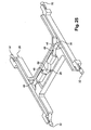
- the armature 26 is generally in the form of an "H" when seen from above and it comprises a central beam 64 of transverse main orientation and rails 66 that extend longitudinally on either side of each transverse end 64a of the beam 64.
- the cross-section of the beam 64, along a vertical longitudinal plane, is in the form of a U open at the top.
- the beam 64 has a horizontal base 68 of transverse main orientation and two transverse vertical flanges 70 that extend, vertically upwards, each longitudinal edge of the base 68.
- a central part 72 of the beam 64 is formed in order to receive the switch 28.
- the central part 72 here has a circular shape complementary to the shape of the body 96 of the switch 28.
- the base 68 of the beam 64 has two openings 74 placed on either side of the central part 72, the connection tabs 76 of the switch 28 being intended to extend through said openings.
- the armature 26 is produced so as to be mounted on a component-carrying support plate 94 of the electronic apparatus.
- the base 68 of the beam 64 has feet 78 which have been cut out and bent vertically downwards and which are capable of being received in associated holes (not shown) in the component-carrying support plate 94 on which the control device 20 is mounted.
- Each rail 66 of the armature 26 consists of a horizontal strip that extends longitudinally in both directions from one end 64a of the beam 64.
- each rail 66 is flexible so as to adapt to the shape of the component-carrying support plate on which the armature 26 is mounted. According to another embodiment, the rails 66 are rigid and do not deform vertically.
- each rail 66 is positioned longitudinally proximal to each intermediate portion 36 of an arm 30 and has bent-up portions 80 that are intended to cooperate with the associated intermediate portion 36 of an arm 30.
- the arms 30 and the levers 46 are made as one piece 56 made of sheet metal, which has been cut, bent and stamped to form a metal frame in the shape of an "8" in top view.
- the one piece 56 has straight sections 58 forming the arms 30 or the levers 46, and has portions 60 forming means for linking and articulating the arms 30 and the levers 46 together.
- Each straight section 58 is made so as not to deform when the control device 20 is subjected to a control action.
- each straight section 58 taken along a plane perpendicular to said section 58, is in the form of a U open downwards, which is made up of an upper horizontal portion 82 and two lateral vertical portions 84.
- the two arms 30 of a pair of arms are aligned longitudinally and are connected together at their second ends 34 via a linking and articulating portion 60.
- This linking and articulating portion 60 connects the first end of a lever 46 to the second ends of the arms of the associated pair of arms 30.
- the linking and articulating portion 60 consists here of a generally rectangular horizontal plate, each transverse longitudinal end edge of which is connected to a second end 34 of an arm 30 via a strip of material having a low elastic resistance to deformation.
- a longitudinal internal transverse end edge is connected to the first end of the associated lever 46 via a strip of material having a low elastic resistance to deformation.
- the second ends 50 of the levers 46 which bear directly on the switch 28, are connected together via another strip of material 86 having a low elastic resistance to deformation.
- the strips of material 86 deform elastically. They thus form means for articulating the arms 30 and the levers 46 together.
- the one piece 56 also has two transverse rods 102 which connect the first ends 32 of two arms 30 together, each rod being positioned at a longitudinal end of the one piece 56.
- the rods 102 allow the first ends 32 of the two arms belonging to two different pairs to move vertically in an identical manner, so as to guarantee that the upper panel 22 remains horizontal during this movement.
- rods 102 ensure longitudinal positioning of the upper panel 22 with respect to the arms 30.
- each arm 30 has a stamped lug 88 made from the horizontal portion 82 of the arm 30, in said intermediate portion 36.
- the lug 88 is in the form of a U open at the top and projecting downwards with respect to the horizontal portion 82.
- the lower end of the lug 88 has a downwardly curved convex shape and bears downwards on the free end 66a of a rail 66 associated with the armature 26.
- Each vertical portion 80 of the free end 66a of the rail 66 has a boss 90 which projects transversely towards the other vertical portion 80 and which is positioned above and at a certain distance away from the lower end of the stamped lug 88.
- each boss 90 in a vertical longitudinal plane, is in the form of a "V" having its tip oriented downwards.
- the transverse distance between the facing bosses 90 is less than the transverse width of the stamped lug 88.
- the stamped lug 88 is mounted on the free end 66a of the rail 66, and is therefore inserted between the bosses 90, by elastic snap-fitting.
- the bosses 90 prevent the arms 30 from separating from the armature 26.
- each lever 46 has a stamped lug 88 made from the horizontal portion 82 of the lever 46, in said intermediate portion 52.
- This stamped lug 88 of the lever 46 is intended to cooperate with a boss 90 formed so as to project longitudinally with respect to the internal face of each flange 70 of the central beam 64.
- each boss 90 in a transverse vertical plane takes the form of a "V", the lower tip of which is oriented downwards.
- the concave upper face 88s of the stamped lug 88 bears upwards on the lower tip of each of the two bosses 90, thus forming the articulation of the lever 46 to the armature 26 about an approximately longitudinal pivot axis.
- each foot 78 of the central beam 64 is positioned here transversely level with a boss 90, in such a way that the material constituting said foot 78 clears an opening 92 in the base 68 positioned beneath the boss 90.
- This opening 92 prevents the stamped lug 88 from coming into contact with the base 68, the pivoting of the lever 46 therefore not being impeded.
- Figures 6 and 7 present cross-sectional half-views of the control device 20 showing, on the left, the rest position of the control device 20 and, on the right, the actuated position of the control device, for which a control action has been exerted on the upper face of the upper panel.
- each arm 30 pivots in its intermediate portion 36 about a transverse axis, in such a way that its first end 32 moves downwards, with the same movement as the upper panel 22, and the second end 34 of the arm 30 moves upwards.
- the movement, shown in Figure 7 of the levers 46 consists of a pivoting movement of its intermediate portion 52 in such a way that its first end 48 moves upwards with the same movement as the second end 34 of each arm 30, and the second end 50 of the lever 46 moves downwards and bears on the pushbutton 98 for actuating the switch 28.
- the control device 20 is compact and all its components are housed in a space bounded horizontally by the peripheral edges 38 of the upper panel 22 and bounded vertically by the upper panel 22 and the armature 26.
- each arm 30 since the second end 34 of each arm 30 bears upwards on the switch 28, either directly or indirectly via the levers 46, the assembly formed by the upper panel 22 and the arms 30 cannot pivot with respect to the support plate about a pivot axis defined by an intermediate portion 36 of an arm, even when the contact point "P" is positioned close to a peripheral edge 38 of the upper panel 22.
- the arms 30, the switch 28 and the support 40 cooperate with one another so as to guide the upper panel 22 in its vertical movement and to keep the upper panel 22 parallel to its horizontal main plane.
- the articulated structure formed by the arms 30, and as the case may be the levers 46, is designed in such a way that the bearing force resulting from the control action is distributed over each arm 30 and is redirected in its entirety towards the switch 28.
- the dimensions of the arms 30 and of the levers 46 are defined in such a manner that the lever arm of each arm 30 and the lever arm of each lever 46 is the same for all the arms and is the same for all the levers 46.
- This lever arm is for example defined by the ratio of the distance between the first end 32, 46 and the intermediate portion 36, 52 of the arm 30 or of the lever 46 to the distance between the intermediate portion 36, 52 and the second end 34, 50 of the arm 30 or of the lever 46.
- the switch 28 is actuated when the pressure of the action is greater than a defined value, independently of the location of the contact point "P" on the upper face 22s of the upper panel 22.
- lever arm for the arms 30 and for the levers 46 makes it possible to predefine the pressure of the control action causing the switch 28 to be actuated.
- the invention has been described with reference to a control device having either two or four arms 30 that are placed symmetrically with respect to a vertical longitudinal mid-plane of the control device 20.
- control device 20 may have a larger number of arms 30, for example eight arms 30 grouped in pairs, which are associated with a total of four levers 46.
- This example is suitable for an upper panel 22 having an octagonal or circular shape.
- the arms 30 and/or the levers 46 need not be oriented longitudinally or transversely, but may be inclined to the longitudinal direction "L” and to the transverse direction "T".
- the main orientation of the control device 20 is horizontal, i.e. the upper panel 22 is horizontal.
- control device 20 may be oriented differently, since the Earth's gravity has no influence on the operation of the control device 20.
- control device 20 may be oriented vertically, that is to say the upper panel 22 lies in a vertical plane.
- the weight of the upper panel 22 is then not supported by the arms 30 and the armature 26, thereby making it possible to use an upper panel of large size and large mass, without any risk of damaging the control device 20.
- Separate means for supporting the upper panel will then be provided in order to position the upper panel 22 with respect to the arms 30 and to the armature 26.
- counterweights are installed on the arms and/or on the levers so as to compensate for the mass of the upper panel 22.
- the control device 20 forms one module of the electronic apparatus, which is independent in its structure and its operation with respect to the other components of the electronic apparatus.
- Figure 22 illustrates an embodiment similar to the one of figures 11A and 11B , in which the upper panel 22 is a control button used in a car vehicle as a "warning button".
- the armature 26 is the lower part of a two parts casing also comprising an upper cover 104, both being plastic moulded parts.
- Figures 24 to 26 illustrate another example in which the upper panel 22 is in the form of a plastic moulded plate in which the two arms 30 are rotatably mounted by their first ends 32.
- the lower armature 26 is also a plastic moulded "frame" in the form of an "H” similar to the frame armature 26 illustrated in figures 1 and 2 .
- the switch 28 is thus centrally arranged.
- the two levers 46 are made as a single piece in the form of a bent transversal rod or wire permitting its torsional elastic deformation to a limited extent when the control device 20 is actuated.
- Each one of the two arms 30 is also in the form of a bent rod or wire permitting its torsional elastic deformation to a limited extent when the control device 20 is actuated.
- the components are assembled in a manner such that the rods 30 and 46 are initially under a slight torsional tension avoiding any play and defining very precise respective positions of the various components.
- FIGS 27 and 28 illustrate an example of a control device on the basis of the principles illustrated in figures 8A and 8B .
- the switch 28 is actuated by means of two pairs of associated arms 30 and levers all made by stamping a metal sheet.
- the upper plastic moulded panel 22 includes four pairs of aligned shafts 30s and 46s for articulating the arms 30 and levers 46 respectively.
- the arms 30 and levers 46 have facing complementary cooperating transversal edges so that the various movements are transmitted from one to the other, and also to create a "structure" which makes a whole, being made of the upper panel 22, the switch 28 and the levers 30 and arms 46.
- Such a structure can directly be positioned on an under (not shown) supporting plate.
Landscapes
- Engineering & Computer Science (AREA)
- General Engineering & Computer Science (AREA)
- Theoretical Computer Science (AREA)
- Human Computer Interaction (AREA)
- Physics & Mathematics (AREA)
- General Physics & Mathematics (AREA)
- Switches With Compound Operations (AREA)
- Push-Button Switches (AREA)
Description
- The invention provides a device for controlling an electronic apparatus, comprising a moveable upper panel on which at least one control action is exerted.
- More particularly, the invention provides a device for controlling an electronic apparatus, comprising a generally flat and horizontal upper panel on an upper face of which a control member is capable of exerting a control action, consisting of a compressive force oriented generally downwards, a lower armature of a support with respect to which armature the upper panel can move in a generally vertically downward movement under the effect of the control action, a switch which is carried by the armature and which can be actuated under the effect of the control action in order to produce a signal for controlling the electronic apparatus, and at least two arms for actuating the switch.
- The control device is designed in such a way that, under the effect of the control action, the upper panel moves downwards in a movement consisting generally of a vertical translation and so as to actuate the switch via the actuating arms.
- The actuating arms cooperate with the upper panel and with the lower armature in order to keep the upper panel substantially parallel to its horizontal plane when the control action is exerted.
- Document
WO-A1-2008/152457 describes and represents a control device for which the actuating arms are articulated to the upper panel and to the armature. - The switch is actuated by a single actuating arm under the effect of the control action, thereby making the system unbalanced depending on whether the control action is exerted on the upper panel at a point positioned close to the position of the switch or at a point away from said switch.
- In addition, each arm is linked to the upper panel, to the lower armature or to the other arms via articulations for which a certain operating play is necessary in order to allow relative movement of the components.
- These operating plays induce that the components of the device move with respect to one another, this having the consequence that the upper panel is not correctly maintained in a horizontal orientation. Another consequence of these relative movements is that the resultant force of the control action is not transmitted uniformly to the switch.
- Document
EP-A1-0.419.145 describes a control device for which each actuating arm is bearing on the upper panel, against the armature or against the other arm. - This embodiment makes it possible to avoid the problems resulting from the operating plays mentioned here above.
- However, according to this embodiment, each arm is connected to the upper panel at a point which is positioned horizontally in a position which is intermediate between the centre of the upper panel and the peripheral edge of the upper panel.
- Thus, when the point of application of the control action on the upper panel is positioned close to the peripheral edge of the upper panel, the upper panel then tilts about an actuating arm.
- Document
US2008/0185279 describes an improved press key structure capable of providing a uniform support to its keycap for preventing the same from slanting by pressing. The structure comprises: a keycap, configured with a bottom surface; a substrate, disposed beneath the keycap; anelastic member 35 disposed on the substrate, which, in conjunction with a conducting plate arranged at its bottom and a circuit board arranged beneath the substrate, provides a switch; and first and second movable panels disposed in a space between the substrate and the keycap. The panels are pivotally coupled with each other by the use of a flange and a groove formed respectively on the neighbouring edges of the panels. The panels are also pivotally coupled to the substrate by support axes arranged at the center of the each panel and support seats arranged on the substrate. Finally, the panels are pivotally coupled to the keycap by the use of pivot axes on the two edges of the panels that are away from each other and pivot seats formed at the bottom surface of the keycap. This arrangement enables the keycap to descend smoothly without tilting even when an off-center force is applied to it. - The object of the invention is to provide an alternate structure for a device for controlling an electronic apparatus permitting the upper panel to be kept parallel to its horizontal plane, irrespective of the position of the point of application of the control action.
- The invention is defined by the independent claims.
- The invention provides a device for controlling an electronic apparatus, comprising a generally flat and horizontal upper panel on an upper face of which a control member is capable of exerting a control action, consisting of a compressive force oriented generally downwards, a lower armature of a support with respect to which armature the upper panel can move in a generally vertically downward movement under the effect of the control action, a switch which is carried by the armature and which can be actuated under the effect of the control action in order to produce a signal for controlling the electronic apparatus, and at least two arms for actuating the switch, each arm comprising a first end which bears vertically upwards on a lower face of the upper panel, a second end which bears on, or presses against, the switch, and an intermediate portion which bears vertically downwards on an upper face of the armature and around which portion each arm can pivot about a horizontal geometric pivot axis, in which the arms cooperate with the upper panel and the armature in order to keep the upper panel parallel to a horizontal plane during its vertical movement with respect to the armature.
- The invention also provides a device for controlling an electronic apparatus, comprising a generally flat and horizontal upper panel on an upper face of which a control member is capable of exerting a control action, consisting of a compressive force oriented generally downwards, a lower armature of a support with respect to which armature the upper panel can move in a generally vertically downward movement under the effect of the control action, a switch which is carried by the upper panel and can be actuated under the effect of the control action in order to produce a signal for controlling the electronic apparatus, and at least two arms for actuating the switch, each arm comprising a first end which bears vertically downwards on an upper face of the armature, a second end which bears on the switch, and an intermediate portion which bears vertically upwards on a lower face of the upper panel and around which intermediate portion each arm can pivot about a horizontal geometric pivot axis, in which device the arms cooperate with the upper panel and the armature in order to keep the upper panel parallel to a horizontal plane during its vertical movement with respect to the armature.
- According to embodiments of the invention :
- the switch is interposed vertically between the second end of each arm and at least one support which is stationary with respect to the armature;
- the arms bear on the switch via at least one lever articulated to a support about a horizontal axis, said support being stationary with respect to the armature;
- the switch is interposed vertically between the second end of each arm and at least one support which is stationary with respect to the upper panel;
- the arms bear on the switch via at least one lever articulated to a support about a horizontal axis, said support being stationary with respect to the upper panel;
- said lever has a first end on which the second end of each arm bears and a second end which bears directly on the switch;
- the switch is compressed vertically between the armature and a second end of said at least one lever;
- the switch is compressed vertically between the upper panel and a second end of said at least one lever;
- the first end of each arm is positioned horizontally in line with a peripheral edge of the upper panel;
- the switch is positioned horizontally, generally in line with the centre of the upper panel;
- the device has two arms placed horizontally and generally symmetrically with respect to the switch;
- the device has two pairs of arms and two levers, each lever being associated with a pair of arms, in such a way that the second end of the arms of one pair of arms bears on a first end of the lever associated with said pair of arms and in such a way that the second end of each lever acts on the switch; and
- the dimensional ratio of each arm, of a first distance, between the first end of the arm and the intermediate portion of the arm, by a second distance, between the intermediate portion of the arm and the second end of the arm, is identical for all the arms.
- Other features and advantages of the invention will become apparent on reading the following detailed description, to understand which reference will be made to the appended figures in which:
-
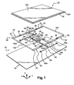
Figure 1 is a schematic representation, in exploded perspective, of a control device according to the invention; -
Figure 2 is a detail on a larger scale of the armature of the control device illustrated inFigure 1 ; -
Figure 3 is a detail on a larger scale of the single part, illustrated inFigure 1 , comprising the levers and the arms; -
Figure 4 is a sectional view, along a transverse vertical plane, of the device illustrated inFigure 1 , showing a detail of the articulation of a lever with respect to the armature; -
Figure 5 is a sectional view, along a vertical longitudinal plane of the device illustrated inFigure 1 , showing a detail of the articulation of an arm with respect to the armature; -
Figure 6 represents two half-views of the control device according to the invention, showing the movement of the arms during the actuation of the control device according to the invention; -
Figure 7 represents two half-views of the control device according to the invention, showing the movement of the levers during the actuation of the control device according to the invention; -
Figures 8A and 8B are schematic sectional representations along a vertical longitudinal plane (Figure 8A ) and in a top view (Figure 8B ) of a first embodiment of the invention, in whichfigures 8A and 8B the control device comprises only two actuating arms and in which the switch is carried by the support armature; -
Figures 9A and 9B are views similar to those ofFigures 8A and 8B , in which the control device comprises four actuating arms; -
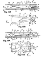
Figures 10A and 10B are views similar to those ofFigures 8A and 8B , in which the control device comprises four actuating arms and in which the switch is offset longitudinally; -
Figures 11A and 11B are views similar to those ofFigures 8A and 8B , in which the control device comprises two actuating arms and one lever articulated with respect to the armature; -
Figures 12A and 12B are views similar to those ofFigures 9A and 9B , in which the control device comprises four actuating arms and one lever articulated with respect to the armature; -
Figures 13A and 13B are views similar to those ofFigures 12A and 12B , andFigure 13C is a sectional view, along a transverse vertical plane, of the control device, in whichfigures 13A and 13B the control device comprises four actuating arms and two levers articulated with respect to the armature; -
Figures 14A to 14C are views similar to those ofFigures 13A to 13C , in which the switch is offset longitudinally with respect to the upper panel; -
Figures 15A to 15C are views similar to those ofFigures 13A to 13C , in which the actuating arms and the levers are made in a single piece; -
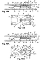
Figures 16A and 16B are views similar to those ofFigures 8A and 8B , in which the switch is carried by the upper panel; -
Figures 17A and 17B are views similar to those ofFigures 9A and 9B , in which the switch is carried by the upper panel; -
Figures 18A and 18B are views similar to those ofFigures 11A and 11B , in which the switch is carried by the upper panel; -
Figures 19A and 19B are views similar to those ofFigures 12A and 12B , in which the switch is carried by the upper panel; -
Figures 20A to 20C are views similar to those ofFigures 13A to 13C , in which the switch is carried by the upper panel; and -
Figures 21A to 21C are views similar to those ofFigures 15A to 15C , in which the switch is carried by the upper panel; -
Figure 22 is a perspective exploded view of an example of the invention in which the control device comprises two actuating arms and one lever articulated with respect to the armature, corresponding to the principles offigures 11A and 11B , being used for the control of a "warning signal" in a car vehicle; -
Figure 23 is an under view of some of the components of the control device illustrated inFigure 22 ; -
Figure 24 is an under perspective view of an other example of the invention in which the control device comprises two actuating arms and one lever articulated with respect to the armature, corresponding to the principles offigures 11A and 11B ; -
Figure 25 is an upper perspective view of the control device offigure 24 , illustrated without the upper panel; -
Figure 26 is a top view of the components ofFigure 25 ; -
Figure 27 is a partially exploded upper perspective view of an example of the invention in which the control device comprises two actuating arms, corresponding to the principles offigures 8A and 8B ; -
Figure 28 is an under perspective view showing some of the components illustrated infigure 27 ; -
Figure 29 is an upper perspective view of an example of a control device comprising two arms and two levers made of a stamped sheet of metal; -
Figure 30 is a view similar to the view ofFigure 29 showing the two arms and two levers exploded; -
Figure 31 is an under perspective view of the upper panel of the control device ofFigure 29 equipped with its switch; -
Figure 32 is an upper perspective view of the two arms and two levers assembled and of the switch; -
Figure 33 is an enlarged detail ofFigure 29 . - In the description of the invention, the reference trihedron V, L, T (vertical, longitudinal and transverse orientations) indicated in the figures will be adopted without being limited thereto and without any restrictive reference to the Earth's gravity.
- In the following description, identical, similar or analogous elements will be designated by the same numeral references.
- It has been illustrated in the figures a
device 20 for controlling an electronic apparatus, such as for example a computer, a PDA (Personal Digital Assistant) or a "smart phone", which combines the features of a PDA with those of a digital telephone. - The
control device 20 comprises anupper panel 22 on which a user acts in order to control the electronic apparatus. - The
upper panel 22 consists of a flat element, which here is horizontal and of rectangular shape, the long sides of which are parallel to the longitudinal direction "L". - The operation of actuating the
control device 20 consists in exerting an action, hereafter called the "control action", on theupper face 22s of theupper panel 22 via apointing element 24. Thispointing element 24 is for example a stylus or a finger of the user. - The control action consists of a compressive force mainly oriented vertically downwards, which is exerted by the pointing element at a point of contact "P" between one end of the
pointing element 24 and theupper face 22s of theupper panel 22. - According to one embodiment, the
upper panel 22 consists only of a plate, for example made of a rigid plastic. - According to another embodiment, the
upper panel 22 includes means for locating the geometrical position of the contact point "P" on theupper face 22s of theupper panel 22. Thecontrol device 20 is then of the "touch pad" type, used for example for a portable computer. Theupper panel 22 is then a component usually called a "touch pad". - According to yet another embodiment, the
upper panel 22 includes, in addition to the locating means, information display means, for example a display screen, in order to permit the user to see information relating to the electronic apparatus, and/or information associated with the manipulations that the user performs on theupper panel 22. Theupper panel 22 is then a component usually called a "touch screen". - The
control device 20 is intended to be mounted in the electronic apparatus in a manner such that theupper face 22s of theupper panel 22 is flush with a covering element or casing of the electronic apparatus. - Each
edge 38 of theupper panel 22 has aperipheral rim 100 which is positioned vertically set back with respect to theupper face 22s of theupper panel 22 and is intended to be held beneath the covering element. - Thus, the
rim 100 of theupper panel 22 cooperates with the covering element so that theupper panel 22 butts against the covering element in a high, rest position and for positioning theupper panel 22 horizontally and transversely with respect to the covering element. - The
control device 20 also includes alower armature 26 by means of which thecontrol device 20 is assembled inside the electronic apparatus. - The
armature 26 is shown inFigures 8A et seq. in the form of a flat plate and consists for example of a so-called "component-carrying" support plate on which electronic components and electronic circuits are placed. - According to another embodiment shown in
Figures 1 to 7 , thearmature 26 consists of a frame or framework made of sheet metal, which permits thecontrol device 20 to be mounted and assembled on a support component of the electronic apparatus, for example on a component-carrying support plate. - The
upper panel 22 is mounted so as to move with respect to thearmature 26 in a vertically downward movement when a control action is exerted on theupper face 22s of theupper panel 22. - When the control action is released, the
upper panel 22 moves in the opposite direction, i.e. it undergoes a vertically upward movement with respect to thearmature 26. - The
control device 20 includes aswitch 28, or switchinginterrupter 28, that can be actuated when theupper panel 22 moves downwards under the effect of the control action, generating, as a result, a signal for controlling the electronic apparatus. - The
switch 28 may be of any known type. - The compressive force exerted on the
upper panel 22 is transmitted to theswitch 28 in order for theswitch 28 to be actuated under the effect of the control action. - According to one embodiment, the
switch 28 is capable of generating the control signal when it is submitted to a compressive force greater than a predetermined value. - Thus, the
switch 28 makes it possible to detect any control action consisting in exerting a pressure, greater than the predetermined threshold value, on theupper face 22s of theupper panel 22. - According to another embodiment, when the pressure of the control action is below said threshold value, the
switch 28 constitutes an abutment, or stop, for theupper panel 22 at a certain vertical (height) position with respect to thearmature 26, preventing theupper panel 22 from moving downwards with respect to the armature. In this position, theswitch 28 is not actuated, and therefore the control signal is not generated. - The
switch 28 is able to change state when the pressure of the control action exceeds said threshold value. - Following this change of state, the
switch 28 therefore no longer forms an abutment for theupper panel 22, thus enabling theupper panel 22 to move downwards as far as a position called a position for actuating theswitch 28. - The control signal is then generated when the
switch 28 changes state. - A tactile sensation is also perceived by the user, via the
pointing element 24, when theswitch 28 changes state, especially since the user feels a rapid change in the resistance to the movement of theupper panel 22, in the manner of a "click" of a pushbutton. - The user is thus informed by touch that the control action has been exerted on the
control device 20. - The
control device 20 also hasarms 30 for actuating theswitch 28, which are positioned vertically globally between a horizontallower face 22i of theupper panel 22 and, opposite, anupper face 26s of thearmature 26. - One end of each arm bears on the
switch 28 and each arm cooperates with theupper panel 22 and with thearmature 26 in order to actuate theswitch 28 when a control action is exerted on theupper face 22s of theupper panel 22. - In addition, the actuating
arms 30 cooperate with theupper panel 22 and with thearmature 26 in order to keep theupper panel 22 parallel to a horizontal plane, when theupper panel 22 moves vertically with respect to thearmature 26. -
Figures 8A to 15B show a first example of the control device in which theswitch 28 is carried by thearmature 26. - Moreover, in this example, each arm has a
first end 32 which bears vertically upwards on thelower face 22i of theupper panel 22, asecond end 34 which bears on theswitch 28, and anintermediate portion 36 which bears vertically downwards against theupper face 26s of thearmature 26. - Each
arm 30 also has straight portions connecting theintermediate portion 36 to thefirst end 32 and to thesecond end 34. These straight portions are relatively rigid so as to deform to a limited extent when thecontrol device 20 is actuated. - The first ends 32 of the
arms 30 are positioned with respect to theupper panel 22 so that they are positioned respectively at the vertices of a polygon, each of which corresponds to a point where thefirst end 32 of anarm 30 bears on thelower face 22i of theupper panel 22. - Preferably, the
first end 32 of eacharm 30 is positioned horizontally proximal to theperipheral edge 38 of theupper panel 22, so that the area of the polygon is as large as possible. - The
intermediate portion 36 of eacharm 30 bears on theupper face 26s of thearmature 26 in such a way that thearm 30 can pivot with respect to thearmature 26 about a horizontal pivot axis A, located in thisintermediate portion 36. - Thus, during the downward movement of the
upper panel 22, thefirst end 32 of eacharm 30 moves downwards and thesecond end 34 of eacharm 30 moves upwards. -
Figures 8A and 8B show a first embodiment of this example, in which thecontrol device 20 has twoarms 30 placed between theupper panel 22 and thearmature 26 for actuating theswitch 28. - According to this embodiment, the
switch 28 is actuated directly by thesecond end 34 of eacharm 30. - Here, the
switch 28 is positioned horizontally globally at the centre of theupper panel 22. The twoarms 30 are placed horizontally, on each side of theswitch 28, that is to say they are here positioned horizontally, symmetrically with respect to theswitch 28. - Here, each
arm 30 consists of a plate, for example made of sheet metal, which has been cut, bent and stamped so as to define bearing and pivoting points at thefirst end 32, at thesecond end 34 and at theintermediate portion 36. - The
first end 32 of eacharm 30 is positioned proximal to alongitudinal edge 38 of theupper panel 22. - Here, the
first end 32 of eacharm 30 bears on thelower face 22i of theupper panel 22 at two points positioned at the corners of theupper panel 22. These two bearing points are also aligned transversely. - The
intermediate portion 36 of eacharm 30 is positioned longitudinally at a distance intermediate between thefirst end 32 and thesecond end 34 of thearm 30. - Here, the
intermediate portion 36 bears on theupper face 26s of thearmature 26 at two points which are aligned transversely and which define the geometric pivot axis of thearm 30. Thus, this axis is here parallel to the transverse orientation "T". - The
second end 34 of each arm is positioned horizontally in line with theswitch 28, that is to say at the centre of theupper panel 22. - As mentioned above, when a control action is exerted on the
upper panel 22, thearms 30 pivot in such a way that eachsecond end 34 moves upwards and thearms 30 therefore generate an upwardly directed pressure. - To allow the
switch 28 to be actuated by this upwardly directed pressure of thesecond end 34 of eacharm 30, theswitch 28 is placed above the second ends 34 of thearms 30 and is interposed vertically between thesecond end 34 of eacharm 30 and asupport 40 on which theswitch 28 is mounted and which is fixedly carried by thearmature 26. - The
support 40 comprises ahorizontal support plate 42 which is placed vertically above and at a certain vertical distance from theupper face 26s of thearmature 26. Thesupport 40 also has an upright 44 connecting thesupport plate 42 to thearmature 26. - The
switch 28 is mounted on a lower face 42i of thesupport plate 42 and is compressed vertically between thesupport plate 42 and thesecond end 34 of eacharm 30. -
Figures 9A and 9B show a variant of the control device, in which the actuatingarms 30 are four in number. - Each
arm 30 consists of a bar that has been bent so that thefirst end 32 of thearm 30 bears on thelower face 22i of theupper panel 22 at a single point, and in such a way that theintermediate portion 36 of thearm 30 bears on theupper face 26s of thearmature 26 at a single point. - The
switch 28 here is also positioned at the centre of theupper panel 22. Thearms 30 are distributed around theswitch 28 in such a way that thefirst end 32 of eacharm 30 is positioned at a corner of theupper panel 22. - Each
arm 30 is oriented radially about a vertical axis centred on theswitch 28. - The
switch 28 is mounted so as to be vertically compressed between thesupport plate 42 of thesupport 40 and thesecond end 34 of eacharm 30. - When a control action is exerted on the upper panel, each
arm 30 pivots with respect to the armature 36about a horizontal pivot axis A positioned in theintermediate portion 36 of thearm 30. This pivot axis is orthogonal to the radial orientation of thearm 30. - This variant of the
control device 20 enables eacharm 30 to be subjected to stresses that lie in a radial plane with respect to the vertical axis centred on theswitch 28. Thus, the arm is not subjected to any torsional stress. -
Figures 10A and 10B show another variant of the control device, in which the actuatingarms 30 are four in number, as described above, and in which theswitch 28 is offset horizontally with respect to the upper panel. - According to this variant, each
arm 30 consists of a bar extending in a radial plane with respect to a vertical axis centred on theswitch 28, and thefirst end 32 of eacharm 30 is positioned at a corner of the upper panel. - In this variant, the
switch 28 and thesupport 40 are therefore not positioned beneath the upper panel. Thus, they cannot interfere with theupper panel 22 during its downward vertical movement. - It is then possible to produce a control device for which the distance between the
upper panel 22 and thearmature 26 is smaller than in the variants illustrated here above, for which the switch is positioned beneath theupper panel 22. -
Figures 11A and 11B show another variant of the control device, in which the actuatingarms 30 are two in number and in which theswitch 28 is mounted directly on theupper face 26s of thearmature 26. - By mounting the
switch 28 directly on thearmature 26, it is easier to mount and to electrically connect theswitch 28, especially when thearmature 26 consists of a support plate carrying electronic components. - The
switch 28 is then actuated when it is subjected to a downwardly directed force. - However, as indicated above, when a control action is exerted on the
upper panel 22, thesecond end 34 of eacharm 30 moves upwards with respect to thearmature 26. - According to this variant, the
switch 28 is actuated by means of onelever 46 which is articulated to asupport 40 about a horizontal axis. - The
support 40 is fixed to theupper face 26s of thearmature 26. - Here, the
lever 46 has afirst end 48 on which thesecond end 34 of eacharm 30 bears on. Asecond end 50 of thelever 46 bears downwards on theswitch 28, and anintermediate portion 52 of thelever 46 is articulated with respect to thesupport 40. - Thus, the
lever 46 permits the upward pressure of thesecond end 34 of eacharm 30 to be converted into a downwardly oriented force on theswitch 28. - The
first end 48 of thelever 46 is positioned horizontally in line with the centre of theupper panel 22. - The
switch 28 and thesecond end 50 of thelever 46 are offset longitudinally with respect to theupper panel 22. - Consequently, the
lever 46 has a mainly longitudinal orientation. -
Figures 12A and 12B show another variant of the control device, in which the actuatingarms 30 are four in number, similarly to the variant shown inFigures 9A and 9B , and in which theswitch 28 is mounted directly on theupper face 26s of thearmature 26. - As in the variant described above, the
switch 28 is actuated by means of onelever 46 which is articulated with respect to asupport 40 about a horizontal axis. Thesupport 40 is fixed to theupper face 26s of thearmature 26. -
Figures 13A to 13C show another variant of the control device, in which the actuatingarms 30 are four in number and in which theswitch 28 is mounted directly on theupper face 26s of thearmature 26. Theswitch 28 is actuated by means of twolevers 46. - The
arms 30 are grouped in pairs, that is to say thecontrol device 20 comprises two pairs of twoarms 30. - The
arms 30 of one pair ofarms 30 are placed along a longitudinal edge of theupper panel 22, i.e. here along one long lateral edge. The main orientation of thearms 30 is therefore longitudinal. - The
second end 34 of each of the twoarms 30 of a pair ofarms 30 is positioned in the middle of said longitudinal edge of theupper panel 22. - Each pair of
arms 30 is associated with onelever 46 which is mounted so as to be articulated with respect to asupport 40 which is itself fixed to thearmature 26. - The
first end 48 of thelever 46, on which the second ends 34 of thearms 30 of the pair ofarms 30 bear, is positioned in line with the middle of said longitudinal edge of theupper panel 22. - The
second end 50 of thelever 46 is positioned proximal to theswitch 28, that is to say, here, in line with the centre of theupper panel 22, and the second end bears directly on the switch. - The
lever 46 is thus oriented mainly perpendicular to thearms 30 of the associated pair ofarms 30, that is to say the lever is oriented here in the transverse direction "T". - According to this variant, the pairs of
arms 30 and thelevers 46 are placed generally symmetrically with respect to a vertical longitudinal mid-plane of thecontrol device 20. - In this variant, the
arms 30, thelevers 46, theupper panel 22 and thearmature 26 define twozones 54 which receive no component of the control device. - These "free"
zones 54 are capable of receiving components independent of thecontrol device 20, such as for example electrical or electronic components that are carried by thearmature 26 or that are carried by a component-carrying support plate on which thearmature 26 is mounted. - The free zones may also receive components that are carried by the
upper panel 22, for example a flexible strip (not shown) for connecting theupper panel 22 to an electronic control circuit. The flexible strip may then be formed freely in a free zone, without coming into contact with another component. -
Figures 14A to 14C show another variant of the control device, in which the actuatingarms 30 are four in number, grouped in two pairs, and in which theswitch 28 is mounted directly on theupper face 26s of thearmature 26. The switch is offset horizontally with respect to theupper panel 22. - In this variant, the
arms 30 have a longitudinal main orientation and each pair ofarms 30 is associated with alever 46 of transverse main orientation which is articulated with respect to asupport 40 fixed to thearmature 26. - The
second end 34 of eacharm 30 is positioned longitudinally with respect to the switch. - The
levers 46 are offset longitudinally with respect to theupper panel 22, like theswitch 28,. - Thus, in this variant, a single
free zone 54 is delimited by the components of thecontrol device 20 and it extends longitudinally over the entire length of theupper panel 22. -
Figures 15A to 15C show another variant of the control device similar to that ofFigures 13A to 13C , in which the actuatingarms 30 are four in number, grouped in pairs, and in which each pair ofarms 30 is associated with alever 46. - In this variant, the
switch 28 is mounted directly on theupper face 26s of thearmature 26 and is positioned in line with the centre of theupper panel 22. - In this variant of the control device, the four
arms 30 and the twolevers 46 are made as a single piece, for example by cutting, bending and/or stamping asheet metal plate 56. - This
single piece 56 hasstraight sections 58 constituting thearms 30 or thelevers 46. - The
single piece 56 also hasportions 60 which are produced so as to be elastically deformable and which connect and articulate thearms 30, and which connect thelevers 46 together, in order to permit their relative movements. - By making the
arms 30 and thelevers 46 as asingle piece 56, it is possible to simplify the construction and the assembly of the control device by reducing the number of components, and thereby lowering the assembly costs of thecontrol device 20. -
Figures 16A to 21C show a second example of thecontrol device 20 in which theswitch 28 is carried by theupper panel 22. - According to this second example, each arm has a
first end 32 which bears vertically downwards on theupper face 26s of thearmature 26, asecond end 34 which bears on theswitch 28, and anintermediate portion 36 which bears vertically on thelower face 22i of theupper panel 22. - The
first end 32 of eacharm 30 is positioned horizontally in line with theperipheral edge 38 of theupper panel 22 in order for the first ends 32 of thearms 30 together to define the vertices of a polygon with the largest possible dimensions. - The
intermediate portion 36 of eacharm 30 bears on thelower face 22i of theupper panel 22 in such a way that thearm 30 can pivot with respect to theupper panel 22 about a horizontal pivot axis "A" located in thisintermediate portion 36. - During the downward movement of the
upper panel 22, theintermediate portion 36 of eacharm 30 is made to move downwards and thesecond end 34 of eacharm 30 moves downwards with respect to theupper panel 22. - The
switch 28 is carried by thelower face 22i of theupper panel 22. Theswitch 28 is also positioned horizontally inside the polygon defined by the first ends 32 of thearms 30. - According to this aspect of the
control device 20, theupper panel 22, thearms 30 and theswitch 28 form a module that bears on theupper face 26s of thearmature 26. - The assembly formed by the
switch 28, by thearms 30, by thesupport 40 and, where appropriate, by thelevers 46 is thus similar to the first example of the invention in which theswitch 28 is carried by thearmature 26. - The correspondence between the second example and the first example is effected globally by symmetry with respect to a horizontal plane.
- As it may be seen in
Figures 16A and 16B , according to this second example of the invention thecontrol device 20 has twoarms 30 placed between theupper panel 22 and thearmature 26 for actuating theswitch 28, in a similar manner to the embodiment shown inFigures 8A and 8B . - According to this embodiment, the
switch 28 is actuated directly by thesecond end 34 of eacharm 30. - The
switch 28 is positioned generally horizontally at the centre of theupper panel 22. The twoarms 30 are placed longitudinally on either side of theswitch 28. - The
switch 28 is carried by asupport 40 which is itself carried by theupper panel 22, and it is mounted so as to be compressed vertically between thesupport plate 42 and thesecond end 34 of eacharm 30. -
Figures 17A and 17B show another variant of the control device, in which the actuatingarms 30 are four in number, in a manner similar to the variant shown inFigures 9A and 9B . - The
switch 28 is positioned at the centre of theupper panel 22, and thearms 30 are distributed around theswitch 28. - The
switch 28 is mounted so as to be compressed vertically between thesupport plate 42 of thesupport 40 and thesecond end 34 of eacharm 30. -
Figures 18A and 18B show another variant of the control device, in which the actuatingarms 30 are two in number and in which theswitch 28 is mounted directly on thelower face 22i of theupper panel 22, in a manner similar to the variant shown inFigures 11A and 11 B . - In this variant, the
switch 28 is actuated by means of alever 46 which is articulated with respect to asupport 40 about a horizontal axis. Thesupport 40 is fixed to thelower face 22i of theupper panel 22. - The
switch 28 and thesecond end 48 of thelever 46 are offset horizontally with respect to the centre of theupper panel 22. -
Figures 19A and 19B show another variant of the control device, in which the actuatingarms 30 are four in number and in which theswitch 28 is mounted directly on thelower face 22i of theupper panel 22, in a manner similar to the variant shown inFigures 12A and 12B . - As in the variant described above, the
switch 28 is actuated by means of alever 46 which is articulated with respect to asupport 40 about a horizontal axis. Thesupport 40 is fixed to thelower face 22i of theupper panel 22. - Each
arm 30 is oriented radially with respect to a vertical axis positioned at the centre of theupper panel 22, in which the first end of thelever 46 is positioned. -
Figures 20A to 20C show another variant of the control device, in which the actuatingarms 30 are four in number and in which theswitch 28 is mounted directly on thelower face 22i of theupper panel 22 and is positioned in line with the centre of theupper panel 22, in a manner similar to the variant shown inFigures 13A to 13C . - The
arms 30 are grouped in pairs, that is to say here thecontrol device 20 has two pairs ofarms 30. - Each pair of
arms 30 is positioned along one edge of theupper panel 22, and alever 46, mounted so as to be articulated with respect to asupport 40 fixed to theupper panel 22, is associated with each pair ofarms 30. - The
lever 46 is oriented here mainly perpendicular to thearms 30 of the associated pair ofarms 30, that is to say the lever is here oriented in the transverse direction "T". - In this variant, in a manner similar to the variant shown in
Figures 13A to 13C , twofree zones 54 are delimited horizontally by thearms 30 and thelevers 46 and delimited vertically by theupper panel 22 and thearmature 26, thesefree zones 54 receiving no component of the control device. -
Figures 21 A to 21C show another variant of the control device, similar to the variant shown inFigures 15A to 15C , in which the actuatingarms 30 are four in number and are grouped in pairs. According to this variant, theswitch 28 is mounted directly on thelower face 22i of theupper panel 22 and is positioned in line with the centre of theupper panel 22. - Each pair of
arms 30 is associated with alever 46 of mainly transverse orientation, which is articulated to asupport 40 fixed to theupper panel 22 and is positioned longitudinally at the centre of theupper panel 22. -
Figures 1 to 7 show an exemplary embodiment of thecontrol device 20 according to the invention for which thearms 30 and thelevers 46 are made as a single piece and for which theswitch 28 is carried by thearmature 26. - As described above with reference to the variant shown in
Figures 15A to 15C , thefirst end 32 of each arm bears on thelower face 22i of theupper panel 22 and theintermediate portion 36 of each arm bears downwards on thearmature 26. - The
arms 30 have a longitudinal main orientation and are grouped in pairs ofarms 30, the twoarms 30 of a pair of arms being placed along one longitudinal edge of theupper panel 22. - The
control device 20 has twolevers 46 of transverse main orientation, each of which is associated with a pair ofarms 30, and eachlever 46 is articulated with respect to asupport 40 fixed to thearmature 26. - The
switch 28 has acylindrical body 96 which carriesconnection tabs 76 of theswitch 28, by means of which theswitch 28 is electrically connected to a circuit for controlling the electronic apparatus. - The
switch 28 also has atop pushbutton 98 on which the second ends 50 of thelevers 46 bear in order to actuate theswitch 28. - The
upper panel 22 here is a flat horizontal element of rectangular shape with a longitudinal main orientation, i.e. its long sides are parallel to the longitudinal orientation "L". - The control device is intended to be mounted in the electronic apparatus in such a way that the
upper face 22s of theupper panel 22 is flush with a covering element or case of the electronic apparatus (not illustrated infigures 1 to 7 ). - Each
edge 38 of theupper panel 22 has aperipheral rim 100 which is positioned vertically set back with respect to theupper face 22s of theupper panel 22 and is intended to be received beneath the covering element. - Thus, the
rim 100 of theupper panel 22 cooperates with the covering element so that theupper panel 22 abuts against the covering element in a high, rest position, and for positioning theupper panel 22 horizontally and transversely with respect to the covering element. - As it may be seen in
Figure 2 , thearmature 26 here takes the form of a piece made of sheet metal, which has been cut, bent and stamped. - The
armature 26 is generally in the form of an "H" when seen from above and it comprises acentral beam 64 of transverse main orientation and rails 66 that extend longitudinally on either side of eachtransverse end 64a of thebeam 64. - The cross-section of the
beam 64, along a vertical longitudinal plane, is in the form of a U open at the top. In cross-section, thebeam 64 has ahorizontal base 68 of transverse main orientation and two transversevertical flanges 70 that extend, vertically upwards, each longitudinal edge of thebase 68. - A
central part 72 of thebeam 64 is formed in order to receive theswitch 28. Thecentral part 72 here has a circular shape complementary to the shape of thebody 96 of theswitch 28. - The
base 68 of thebeam 64 has twoopenings 74 placed on either side of thecentral part 72, theconnection tabs 76 of theswitch 28 being intended to extend through said openings. - The
armature 26 is produced so as to be mounted on a component-carryingsupport plate 94 of the electronic apparatus. - For this purpose, the
base 68 of thebeam 64 hasfeet 78 which have been cut out and bent vertically downwards and which are capable of being received in associated holes (not shown) in the component-carryingsupport plate 94 on which thecontrol device 20 is mounted. - Each
rail 66 of thearmature 26 consists of a horizontal strip that extends longitudinally in both directions from oneend 64a of thebeam 64. - According to one embodiment, each
rail 66 is flexible so as to adapt to the shape of the component-carrying support plate on which thearmature 26 is mounted. According to another embodiment, therails 66 are rigid and do not deform vertically. - The
free end 66a of eachrail 66 is positioned longitudinally proximal to eachintermediate portion 36 of anarm 30 and has bent-upportions 80 that are intended to cooperate with the associatedintermediate portion 36 of anarm 30. - As illustrated in
Figure 3 , thearms 30 and thelevers 46 are made as onepiece 56 made of sheet metal, which has been cut, bent and stamped to form a metal frame in the shape of an "8" in top view. - As described above, the one
piece 56 hasstraight sections 58 forming thearms 30 or thelevers 46, and hasportions 60 forming means for linking and articulating thearms 30 and thelevers 46 together. - Each
straight section 58 is made so as not to deform when thecontrol device 20 is subjected to a control action. - To this end, the cross-section of each
straight section 58, taken along a plane perpendicular to saidsection 58, is in the form of a U open downwards, which is made up of an upperhorizontal portion 82 and two lateralvertical portions 84. - The two
arms 30 of a pair of arms are aligned longitudinally and are connected together at their second ends 34 via a linking and articulatingportion 60. - This linking and articulating
portion 60 connects the first end of alever 46 to the second ends of the arms of the associated pair ofarms 30. - The linking and articulating
portion 60 consists here of a generally rectangular horizontal plate, each transverse longitudinal end edge of which is connected to asecond end 34 of anarm 30 via a strip of material having a low elastic resistance to deformation. A longitudinal internal transverse end edge is connected to the first end of the associatedlever 46 via a strip of material having a low elastic resistance to deformation. - The second ends 50 of the
levers 46, which bear directly on theswitch 28, are connected together via another strip ofmaterial 86 having a low elastic resistance to deformation. - During the upward or downward movement of the
upper panel 22, the strips ofmaterial 86 deform elastically. They thus form means for articulating thearms 30 and thelevers 46 together. - The one
piece 56 also has twotransverse rods 102 which connect the first ends 32 of twoarms 30 together, each rod being positioned at a longitudinal end of the onepiece 56. - The
rods 102 allow the first ends 32 of the two arms belonging to two different pairs to move vertically in an identical manner, so as to guarantee that theupper panel 22 remains horizontal during this movement. - In addition, the
rods 102 ensure longitudinal positioning of theupper panel 22 with respect to thearms 30. - As it may be seen in greater detail in
Figure 5 , theintermediate portion 36 of eacharm 30 has a stampedlug 88 made from thehorizontal portion 82 of thearm 30, in saidintermediate portion 36. - The
lug 88 is in the form of a U open at the top and projecting downwards with respect to thehorizontal portion 82. The lower end of thelug 88 has a downwardly curved convex shape and bears downwards on thefree end 66a of arail 66 associated with thearmature 26. - Due to the
lug 88 bearing on therail 66, it is possible for thearm 30 to pivot with respect to saidrail 66 about a transverse pivot axis defined by the line of contact between thelower face 88i of thelug 88 and thefree end 66a of therail 66. - Each
vertical portion 80 of thefree end 66a of therail 66 has aboss 90 which projects transversely towards the othervertical portion 80 and which is positioned above and at a certain distance away from the lower end of the stampedlug 88. - The cross-section of each
boss 90, in a vertical longitudinal plane, is in the form of a "V" having its tip oriented downwards. The transverse distance between the facingbosses 90 is less than the transverse width of the stampedlug 88. - The stamped
lug 88 is mounted on thefree end 66a of therail 66, and is therefore inserted between thebosses 90, by elastic snap-fitting. Thebosses 90 prevent thearms 30 from separating from thearmature 26. - As may be seen in greater detail in
Figure 4 , theintermediate portion 52 of eachlever 46 has a stampedlug 88 made from thehorizontal portion 82 of thelever 46, in saidintermediate portion 52. - This stamped
lug 88 of thelever 46 is intended to cooperate with aboss 90 formed so as to project longitudinally with respect to the internal face of eachflange 70 of thecentral beam 64. - The cross-section of each
boss 90 in a transverse vertical plane takes the form of a "V", the lower tip of which is oriented downwards. - The concave
upper face 88s of the stampedlug 88 bears upwards on the lower tip of each of the twobosses 90, thus forming the articulation of thelever 46 to thearmature 26 about an approximately longitudinal pivot axis. - Consequently, the
bosses 90 and theflanges 70 of thecentral beam 64 form asupport 40 associated with thelever 46. - In addition, each
foot 78 of thecentral beam 64 is positioned here transversely level with aboss 90, in such a way that the material constituting saidfoot 78 clears anopening 92 in the base 68 positioned beneath theboss 90. - This
opening 92 prevents the stampedlug 88 from coming into contact with thebase 68, the pivoting of thelever 46 therefore not being impeded. -
Figures 6 and 7 present cross-sectional half-views of thecontrol device 20 showing, on the left, the rest position of thecontrol device 20 and, on the right, the actuated position of the control device, for which a control action has been exerted on the upper face of the upper panel. - As may be seen in
Figure 6 , when the control action is exerted on theupper face 22s of theupper panel 22, eacharm 30 pivots in itsintermediate portion 36 about a transverse axis, in such a way that itsfirst end 32 moves downwards, with the same movement as theupper panel 22, and thesecond end 34 of thearm 30 moves upwards. - At the same time, the movement, shown in
Figure 7 , of thelevers 46 consists of a pivoting movement of itsintermediate portion 52 in such a way that itsfirst end 48 moves upwards with the same movement as thesecond end 34 of eacharm 30, and thesecond end 50 of thelever 46 moves downwards and bears on thepushbutton 98 for actuating theswitch 28. - The
control device 20 according to the invention is compact and all its components are housed in a space bounded horizontally by theperipheral edges 38 of theupper panel 22 and bounded vertically by theupper panel 22 and thearmature 26. - In addition, since the
second end 34 of eacharm 30 bears upwards on theswitch 28, either directly or indirectly via thelevers 46, the assembly formed by theupper panel 22 and thearms 30 cannot pivot with respect to the support plate about a pivot axis defined by anintermediate portion 36 of an arm, even when the contact point "P" is positioned close to aperipheral edge 38 of theupper panel 22. - The
arms 30, theswitch 28 and thesupport 40 cooperate with one another so as to guide theupper panel 22 in its vertical movement and to keep theupper panel 22 parallel to its horizontal main plane. - The articulated structure formed by the
arms 30, and as the case may be thelevers 46, is designed in such a way that the bearing force resulting from the control action is distributed over eacharm 30 and is redirected in its entirety towards theswitch 28. - The dimensions of the
arms 30 and of thelevers 46 are defined in such a manner that the lever arm of eacharm 30 and the lever arm of eachlever 46 is the same for all the arms and is the same for all thelevers 46. - This lever arm is for example defined by the ratio of the distance between the
first end intermediate portion arm 30 or of thelever 46 to the distance between theintermediate portion second end arm 30 or of thelever 46. - Consequently, the
switch 28 is actuated when the pressure of the action is greater than a defined value, independently of the location of the contact point "P" on theupper face 22s of theupper panel 22. - In addition, the choice of the lever arm for the
arms 30 and for thelevers 46 makes it possible to predefine the pressure of the control action causing theswitch 28 to be actuated. - This choice of the lever arm also makes it possible to determine the vertical movement travel of the
upper panel 22. - The invention has been described with reference to a control device having either two or four
arms 30 that are placed symmetrically with respect to a vertical longitudinal mid-plane of thecontrol device 20. - It will be understood that the invention is not limited to these embodiments and that the number of
arms 30 and the number oflevers 46, together with their orientations, may be different from the embodiments described. - For example, the
control device 20 may have a larger number ofarms 30, for example eightarms 30 grouped in pairs, which are associated with a total of fourlevers 46. This example is suitable for anupper panel 22 having an octagonal or circular shape. - Thus, the
arms 30 and/or thelevers 46 need not be oriented longitudinally or transversely, but may be inclined to the longitudinal direction "L" and to the transverse direction "T". - In addition, in the above description, the main orientation of the
control device 20 is horizontal, i.e. theupper panel 22 is horizontal. - It will be understood that the
control device 20 according to the invention may be oriented differently, since the Earth's gravity has no influence on the operation of thecontrol device 20. - For example, the
control device 20 may be oriented vertically, that is to say theupper panel 22 lies in a vertical plane. - The weight of the
upper panel 22 is then not supported by thearms 30 and thearmature 26, thereby making it possible to use an upper panel of large size and large mass, without any risk of damaging thecontrol device 20. Separate means for supporting the upper panel will then be provided in order to position theupper panel 22 with respect to thearms 30 and to thearmature 26. - According to yet another aspect of the control device, especially when the upper panel is of large mass, counterweights are installed on the arms and/or on the levers so as to compensate for the mass of the
upper panel 22. - Thus, despite the mass of the
upper panel 22, no action is exerted on theswitch 28 when the user exerts no control action. There is therefore a lower risk of theswitch 28 being actuated unintentionally. - The
control device 20 according to the invention forms one module of the electronic apparatus, which is independent in its structure and its operation with respect to the other components of the electronic apparatus. - It is thus possible for the
complete control device 20 to be mounted entirely and tested on a dedicated station, especially by a subcontractor of the electronic apparatus manufacturer. - By testing the
complete control device 20 before it is assembled, this test may be simplified, and onlyfunctional control devices 20 may be delivered. -
Figure 22 illustrates an embodiment similar to the one offigures 11A and 11B , in which theupper panel 22 is a control button used in a car vehicle as a "warning button". - The
armature 26 is the lower part of a two parts casing also comprising anupper cover 104, both being plastic moulded parts. - When compared with the one schematically illustrated in
figures 11A and 11B , the orientation of thelever 46 is transversal. - It is thus possible to have a large button and to implement a light source on the upper face of the
armature 26 between the twoarms 30 and the two parallel and transversal branches of thelever 46 terminating in a "double"first end 48. -
Figures 24 to 26 illustrate another example in which theupper panel 22 is in the form of a plastic moulded plate in which the twoarms 30 are rotatably mounted by their first ends 32. - The
lower armature 26 is also a plastic moulded "frame" in the form of an "H" similar to theframe armature 26 illustrated infigures 1 and2 . Theswitch 28 is thus centrally arranged. - The two
levers 46 are made as a single piece in the form of a bent transversal rod or wire permitting its torsional elastic deformation to a limited extent when thecontrol device 20 is actuated. - Each one of the two
arms 30 is also in the form of a bent rod or wire permitting its torsional elastic deformation to a limited extent when thecontrol device 20 is actuated. - The fact that the torsion is used in these rods or
wires button 22. - The components are assembled in a manner such that the
rods -
Figures 27 and 28 illustrate an example of a control device on the basis of the principles illustrated infigures 8A and 8B . - It can be seen how the
armature 26 and the twoarms 30 can be realized in plastic moulded parts. - In the example illustrated in
figure 29 and following, theswitch 28 is actuated by means of two pairs of associatedarms 30 and levers all made by stamping a metal sheet. - The upper plastic moulded
panel 22 includes four pairs of alignedshafts arms 30 and levers 46 respectively. - The
arms 30 and levers 46 have facing complementary cooperating transversal edges so that the various movements are transmitted from one to the other, and also to create a "structure" which makes a whole, being made of theupper panel 22, theswitch 28 and thelevers 30 andarms 46. Such a structure can directly be positioned on an under (not shown) supporting plate.
Claims (16)
- Device (20) for controlling an electronic apparatus, comprising:a generally flat and horizontal upper panel (22) on an upper face (22s) of which a control member (24) is capable of exerting a control action, consisting of a compressive force oriented generally downwards;a lower armature (26) of a support (40) with respect to which armature the upper panel (22) can move in a generally vertically downward movement under the effect of the control action;a switch (28) which is carried by the armature (26) and can be actuated under the effect of the control action in order to produce a signal for controlling the electronic apparatus; andat least two arms (30) for actuating the switch (28), each arm (30) comprising:- a first end (32) which bears vertically upwards on a lower face (22i) of the upper panel (22),- a second end (34) which bears on the switch (28), and- an intermediate portion (36) which bears vertically downwards on an upper face (26s) of the armature (26) and around which intermediate portion each arm (30) can pivot about a horizontal geometric pivot axis (A),in which device the arms (30) cooperate with the upper panel (22) and the armature (26) in order to keep the upper panel (22) parallel to a horizontal plane during its vertical movement with respect to the armature (26).
- Device (20) according to the preceding claim, characterized in that the switch (28) is interposed vertically between the second end (34) of each arm (30) and at least one support (40) which is stationary with respect to the armature (26).
- Device (20) according to Claim 1, characterized in that the arms (30) bear on the switch (28) via at least one lever (46) articulated to the support (40) about a horizontal axis, said support (40) being stationary with respect to the armature (26).
- Device (20) for controlling an electronic apparatus, comprising:a generally flat and horizontal upper panel (22) on an upper face (22s) of which a control member (24) is capable of exerting a control action, consisting of a compressive force oriented generally downwards;a lower armature (26) of a support (40) with respect to which armature the upper panel (22) can move in a generally vertically downward movement under the effect of the control action;a switch (28) which is carried by the upper panel (22) and can be actuated under the effect of the control action in order to produce a signal for controlling the electronic apparatus; andat least two arms (30) for actuating the switch (28), each arm (30) comprising:- a first end (32) which bears vertically downwards on an upper face (26s) of the armature (26),- a second end (34) which bears on the switch (28), and- an intermediate portion (36) which bears vertically upwards on a lower face (22i) of the upper panel (22) and around which portion each arm (30) can pivot about a horizontal geometric pivot axis (A),in which the arms (30) cooperate with the upper panel (22) and the armature (26) in order to keep the upper panel (22) parallel to a horizontal plane during its vertical movement with respect to the armature (26).
- Device (20) according to the preceding claim, characterized in that the switch (28) is interposed vertically between the second end (34) of each arm (30) and at least one support (40) which is stationary with respect to the upper panel (22).
- Device (20) according to Claim 4, characterized in that the arms (30) bear on the switch (28) via at least one lever (46) articulated to the support (40) about a horizontal axis, said support (40) being stationary with respect to the upper panel (22).
- Device (20) according to Claim 3 or 6, characterized in that said lever (46) has a first end (48) on which the second end (34) of each arm (30) bears and a second end (50) which bears directly on the switch (28).
- Device (20) according to the preceding claim, in combination with Claim 1, characterized in that the switch (28) is compressed vertically between the armature (26) and a second end (50) of said at least one lever (46).
- Device (20) according to Claim 7, in combination with Claim 3, characterized in that the switch (28) is compressed vertically between the upper panel (22) and a second end (50) of said at least one lever (46).
- Device (20) according to claim 1 or 4 , characterized in that the first end (32) of each arm (30) is positioned horizontally in line with a peripheral edge (38) of the upper panel (22).
- Device (20) according to claim 1 or 4, characterized in that the switch (28) is positioned horizontally, generally in line with the centre of the upper panel (22).
- Device (20) according to the preceding claim, characterized in that it has two arms (30) placed horizontally and generally symmetrically with respect to the switch (28).
- Device (20) according to Claim 4 or 5, characterized in that it has two pairs of arms (30) and two levers (46), each lever (46) being associated with a pair of arms (30), in such a way that the second end (34) of the arms (30) of one pair of arms (30) bears on a first end (48) of the lever (46) associated with said pair of arms (30) and in such a way that the second end (50) of each lever (46) acts on the switch (28).
- Device (20) according to claim 1 or 4, characterized in that the dimensional ratio of each arm (30), of a first distance, between the first end of the arm (30) and the intermediate portion of the arm (30), by a second distance, between the intermediate portion of the arm (30) and the second end of the arm (30), is identical for all the arms (30).
- Device (20) according to claim 1 or 4, characterized in that counterweights are installed on the arms, so as to compensate for the mass of the upper panel 22.
- Device (20) according to claim 3 or 6, characterized in that counterweights are installed on the levers, so as to compensate for the mass of the upper panel 22.
Applications Claiming Priority (2)
| Application Number | Priority Date | Filing Date | Title |
|---|---|---|---|
| FR0954492A FR2947645B1 (en) | 2009-07-01 | 2009-07-01 | CONTROL DEVICE HAVING A MOBILE UPPER PANEL AND ACTUATING ARMS OF A SWITCHING SWITCH |
| PCT/EP2010/059359 WO2011000910A1 (en) | 2009-07-01 | 2010-07-01 | Control device comprising a moveable upper panel and arms for actuating a switch |
Publications (2)
| Publication Number | Publication Date |
|---|---|
| EP2449448A1 EP2449448A1 (en) | 2012-05-09 |
| EP2449448B1 true EP2449448B1 (en) | 2013-05-15 |
Family
ID=41651442
Family Applications (1)
| Application Number | Title | Priority Date | Filing Date |
|---|---|---|---|
| EP10732683.7A Active EP2449448B1 (en) | 2009-07-01 | 2010-07-01 | Control device comprising a moveable upper panel and arms for actuating a switch |
Country Status (5)
| Country | Link |
|---|---|
| US (1) | US8829378B2 (en) |
| EP (1) | EP2449448B1 (en) |
| CN (1) | CN102473039B (en) |
| FR (1) | FR2947645B1 (en) |
| WO (1) | WO2011000910A1 (en) |
Cited By (2)
| Publication number | Priority date | Publication date | Assignee | Title |
|---|---|---|---|---|
| DE102020115847A1 (en) | 2020-06-16 | 2021-12-16 | Behr-Hella Thermocontrol Gmbh | Control unit for a vehicle |
| EP3934930B1 (en) * | 2019-03-06 | 2023-05-24 | Volkswagen Aktiengesellschaft | Circuit arrangement |
Families Citing this family (26)
| Publication number | Priority date | Publication date | Assignee | Title |
|---|---|---|---|---|
| FR2959382B1 (en) * | 2010-04-21 | 2022-01-28 | Valeo Systemes Thermiques | HUMAN-MACHINE INTERFACE WITH REINFORCED HOUSING |
| US20130164068A1 (en) | 2011-12-21 | 2013-06-27 | Apple Inc. | Bonded keyboard and method for making the same |
| GB2499021A (en) * | 2012-02-03 | 2013-08-07 | Secondsync Ltd | Reporting the impact of broadcasts |
| FR2989182B1 (en) * | 2012-04-05 | 2015-06-26 | Coactive Technologies Llc | CONTROL DEVICE HAVING A MOBILE UPPER PANEL FOR ACTUATING A SWITCHING SWITCH |
| KR101521996B1 (en) * | 2012-11-19 | 2015-05-28 | (주)아이티버스 | Input device having touch pad |
| FR2999779B1 (en) | 2012-12-19 | 2015-02-13 | C & K Components Sas | "ELECTRIC SWITCH ARRANGEMENT AND DEVICE FOR CONTROLLING AN APPARATUS HAVING SUCH ARRANGEMENT" |
| TW201502747A (en) * | 2013-07-02 | 2015-01-16 | Elan Microelectronics Corp | Input device and lifting structure applying to the input device |
| WO2015030830A1 (en) * | 2013-08-31 | 2015-03-05 | Hewlett Packard Development Company, L.P. | Touchpad bar |
| FR3011948B1 (en) | 2013-10-11 | 2017-03-03 | C&K Components S A S | METHOD FOR INITIALLY ADJUSTING A DEVICE FOR CONTROLLING AN ELECTRONIC DEVICE |
| US10256057B2 (en) | 2015-03-05 | 2019-04-09 | Dolby Laboratories Licensing Corporation | Mechanical structure for button on satellite microphone |
| TWI587337B (en) | 2015-07-08 | 2017-06-11 | 達方電子股份有限公司 | Keyswitch and keyboard thereof |
| US9955594B2 (en) * | 2015-07-13 | 2018-04-24 | Denso Wave Incorporated | Operation device |
| TWI573159B (en) * | 2015-07-23 | 2017-03-01 | 達方電子股份有限公司 | Keyswitch and keyboard thereof |
| US10068727B2 (en) | 2015-08-04 | 2018-09-04 | Apple Inc. | Key surface lighting |
| US20170192642A1 (en) * | 2015-12-31 | 2017-07-06 | Opentv, Inc. | Systems and methods for enabling transitions between items of content based on swipe gestures |
| DE102017220780B3 (en) * | 2017-11-21 | 2019-02-21 | Volkswagen Aktiengesellschaft | Tactile switch and motor vehicle with a push button |
| FR3089658B1 (en) * | 2018-12-06 | 2021-08-27 | C&K Components S A S | Device for controlling an electronic device, methods of adjusting the device and a motor vehicle mirror incorporating such a device. |
| DE102018222088B3 (en) | 2018-12-18 | 2020-06-18 | Volkswagen Aktiengesellschaft | Key switch and motor vehicle with a key switch |
| WO2021101517A1 (en) * | 2019-11-19 | 2021-05-27 | Hewlett-Packard Development Company, L.P. | Input devices |
| CN112882582B (en) * | 2019-11-29 | 2023-09-01 | 华为技术有限公司 | Touch panel assembly and electronic device |
| US11429157B2 (en) * | 2020-02-21 | 2022-08-30 | Apple Inc. | Parallel motion trackpad |
| TWI775251B (en) * | 2020-12-22 | 2022-08-21 | 宏碁股份有限公司 | Touch pad structure |
| TWI775394B (en) * | 2021-04-21 | 2022-08-21 | 宏碁股份有限公司 | Touch pad structure |
| CN115793779B (en) | 2022-03-11 | 2023-12-12 | 深圳市汇顶科技股份有限公司 | Touch pad module and electronic device using same |
| WO2023225770A1 (en) * | 2022-05-23 | 2023-11-30 | 深圳市汇顶科技股份有限公司 | Supporting assembly, touchpad and electronic device |
| CN114610117A (en) * | 2022-03-18 | 2022-06-10 | 北京小米移动软件有限公司 | Touch panel assembly and notebook computer |
Family Cites Families (8)
| Publication number | Priority date | Publication date | Assignee | Title |
|---|---|---|---|---|
| GB8921473D0 (en) * | 1989-09-22 | 1989-11-08 | Psion Plc | Input device |
| JP4055378B2 (en) * | 2001-07-06 | 2008-03-05 | 松下電器産業株式会社 | Touch panel switch |
| JP2003280809A (en) * | 2002-03-20 | 2003-10-02 | Matsushita Electric Ind Co Ltd | Electronic appliance |
| JP2004235132A (en) * | 2002-12-03 | 2004-08-19 | Alps Electric Co Ltd | Keyboard |
| TWM320163U (en) * | 2007-02-06 | 2007-10-01 | Darfon Electronics Corp | Button structure |
| US20100172080A1 (en) * | 2007-06-14 | 2010-07-08 | Nokia Corporation | Screen assembly |
| US8253698B2 (en) * | 2007-11-23 | 2012-08-28 | Research In Motion Limited | Tactile touch screen for electronic device |
| DE602007009123D1 (en) * | 2007-11-23 | 2010-10-21 | Research In Motion Ltd | Touch screen for an electronic device |
-
2009
- 2009-07-01 FR FR0954492A patent/FR2947645B1/en not_active Expired - Fee Related
-
2010
- 2010-07-01 WO PCT/EP2010/059359 patent/WO2011000910A1/en active Application Filing
- 2010-07-01 CN CN201080028924.2A patent/CN102473039B/en active Active
- 2010-07-01 US US13/381,739 patent/US8829378B2/en active Active
- 2010-07-01 EP EP10732683.7A patent/EP2449448B1/en active Active
Cited By (4)
| Publication number | Priority date | Publication date | Assignee | Title |
|---|---|---|---|---|
| EP3934930B1 (en) * | 2019-03-06 | 2023-05-24 | Volkswagen Aktiengesellschaft | Circuit arrangement |
| DE102020115847A1 (en) | 2020-06-16 | 2021-12-16 | Behr-Hella Thermocontrol Gmbh | Control unit for a vehicle |
| DE102020115847B4 (en) | 2020-06-16 | 2021-12-23 | Behr-Hella Thermocontrol Gmbh | Control unit for a vehicle |
| WO2021254676A1 (en) | 2020-06-16 | 2021-12-23 | Behr-Hella Thermocontrol Gmbh | Operating unit for a vehicle |
Also Published As
| Publication number | Publication date |
|---|---|
| CN102473039B (en) | 2014-09-17 |
| US20120103773A1 (en) | 2012-05-03 |
| FR2947645B1 (en) | 2011-06-10 |
| FR2947645A1 (en) | 2011-01-07 |
| CN102473039A (en) | 2012-05-23 |
| EP2449448A1 (en) | 2012-05-09 |
| US8829378B2 (en) | 2014-09-09 |
| WO2011000910A1 (en) | 2011-01-06 |
Similar Documents
| Publication | Publication Date | Title |
|---|---|---|
| EP2449448B1 (en) | Control device comprising a moveable upper panel and arms for actuating a switch | |
| US5278371A (en) | Keyswitch assembly with support mechanism coupled to support plate beneath printed circuit board | |
| US5769210A (en) | Scissors-type key switch | |
| US5901837A (en) | Push button switch and manufacturing method of the same | |
| US20040195082A1 (en) | Hinge key switch | |
| US8207463B2 (en) | Miniature switch | |
| JPH1124816A (en) | Keyboard device and personal computer using the keyboard device | |
| JP2006269439A (en) | Key switch and keyboard | |
| US8008593B2 (en) | Switch for seesaw key | |
| EP1139360B1 (en) | Key switch device | |
| US6390699B1 (en) | Keyboard with moveable base plate providing key travel | |
| US7135647B2 (en) | Keyboard | |
| US7817139B2 (en) | Membrane switch, keyboard, and electronic apparatus having keyboard | |
| JPH08124453A (en) | Key switch | |
| WO1995026563A1 (en) | Key assembly and keyboard comprising key retraction and stabilization means | |
| CA1154000A (en) | Keyboard and method of making keyboard | |
| US20020092750A1 (en) | Key device with a scissors mechanism | |
| CN110504114B (en) | Key structure | |
| US4386245A (en) | Normally-closed switching means with over-stroke compensation | |
| JP2020161252A (en) | Hinge structure of button and electronic apparatus | |
| JP4270619B2 (en) | Key switch device and keyboard | |
| JP4320877B2 (en) | Electronics | |
| JP6071727B2 (en) | Seesaw switch device | |
| KR101034002B1 (en) | A keyboard | |
| US20120160656A1 (en) | Keyboard with eccentrical triggering mechanism |
Legal Events
| Date | Code | Title | Description |
|---|---|---|---|
| PUAI | Public reference made under article 153(3) epc to a published international application that has entered the european phase |
Free format text: ORIGINAL CODE: 0009012 |
|
| 17P | Request for examination filed |
Effective date: 20111213 |
|
| AK | Designated contracting states |
Kind code of ref document: A1 Designated state(s): AL AT BE BG CH CY CZ DE DK EE ES FI FR GB GR HR HU IE IS IT LI LT LU LV MC MK MT NL NO PL PT RO SE SI SK SM TR |
|
| DAX | Request for extension of the european patent (deleted) | ||
| GRAP | Despatch of communication of intention to grant a patent |
Free format text: ORIGINAL CODE: EPIDOSNIGR1 |
|
| GRAS | Grant fee paid |
Free format text: ORIGINAL CODE: EPIDOSNIGR3 |
|
| GRAA | (expected) grant |
Free format text: ORIGINAL CODE: 0009210 |
|
| AK | Designated contracting states |
Kind code of ref document: B1 Designated state(s): AL AT BE BG CH CY CZ DE DK EE ES FI FR GB GR HR HU IE IS IT LI LT LU LV MC MK MT NL NO PL PT RO SE SI SK SM TR |
|
| REG | Reference to a national code |
Ref country code: CH Ref legal event code: EP Ref country code: GB Ref legal event code: FG4D |
|
| REG | Reference to a national code |
Ref country code: AT Ref legal event code: REF Ref document number: 612457 Country of ref document: AT Kind code of ref document: T Effective date: 20130615 |
|
| REG | Reference to a national code |
Ref country code: IE Ref legal event code: FG4D |
|
| REG | Reference to a national code |
Ref country code: DE Ref legal event code: R096 Ref document number: 602010007141 Country of ref document: DE Effective date: 20130711 |
|
| REG | Reference to a national code |
Ref country code: AT Ref legal event code: MK05 Ref document number: 612457 Country of ref document: AT Kind code of ref document: T Effective date: 20130515 |
|
| REG | Reference to a national code |
Ref country code: LT Ref legal event code: MG4D |
|
| REG | Reference to a national code |
Ref country code: NL Ref legal event code: VDEP Effective date: 20130515 |
|
| PG25 | Lapsed in a contracting state [announced via postgrant information from national office to epo] |
Ref country code: ES Free format text: LAPSE BECAUSE OF FAILURE TO SUBMIT A TRANSLATION OF THE DESCRIPTION OR TO PAY THE FEE WITHIN THE PRESCRIBED TIME-LIMIT Effective date: 20130826 Ref country code: AT Free format text: LAPSE BECAUSE OF FAILURE TO SUBMIT A TRANSLATION OF THE DESCRIPTION OR TO PAY THE FEE WITHIN THE PRESCRIBED TIME-LIMIT Effective date: 20130515 Ref country code: NO Free format text: LAPSE BECAUSE OF FAILURE TO SUBMIT A TRANSLATION OF THE DESCRIPTION OR TO PAY THE FEE WITHIN THE PRESCRIBED TIME-LIMIT Effective date: 20130815 Ref country code: PT Free format text: LAPSE BECAUSE OF FAILURE TO SUBMIT A TRANSLATION OF THE DESCRIPTION OR TO PAY THE FEE WITHIN THE PRESCRIBED TIME-LIMIT Effective date: 20130916 Ref country code: LT Free format text: LAPSE BECAUSE OF FAILURE TO SUBMIT A TRANSLATION OF THE DESCRIPTION OR TO PAY THE FEE WITHIN THE PRESCRIBED TIME-LIMIT Effective date: 20130515 Ref country code: IS Free format text: LAPSE BECAUSE OF FAILURE TO SUBMIT A TRANSLATION OF THE DESCRIPTION OR TO PAY THE FEE WITHIN THE PRESCRIBED TIME-LIMIT Effective date: 20130915 Ref country code: FI Free format text: LAPSE BECAUSE OF FAILURE TO SUBMIT A TRANSLATION OF THE DESCRIPTION OR TO PAY THE FEE WITHIN THE PRESCRIBED TIME-LIMIT Effective date: 20130515 Ref country code: SE Free format text: LAPSE BECAUSE OF FAILURE TO SUBMIT A TRANSLATION OF THE DESCRIPTION OR TO PAY THE FEE WITHIN THE PRESCRIBED TIME-LIMIT Effective date: 20130515 Ref country code: GR Free format text: LAPSE BECAUSE OF FAILURE TO SUBMIT A TRANSLATION OF THE DESCRIPTION OR TO PAY THE FEE WITHIN THE PRESCRIBED TIME-LIMIT Effective date: 20130816 Ref country code: SI Free format text: LAPSE BECAUSE OF FAILURE TO SUBMIT A TRANSLATION OF THE DESCRIPTION OR TO PAY THE FEE WITHIN THE PRESCRIBED TIME-LIMIT Effective date: 20130515 |
|
| PG25 | Lapsed in a contracting state [announced via postgrant information from national office to epo] |
Ref country code: PL Free format text: LAPSE BECAUSE OF FAILURE TO SUBMIT A TRANSLATION OF THE DESCRIPTION OR TO PAY THE FEE WITHIN THE PRESCRIBED TIME-LIMIT Effective date: 20130515 Ref country code: BG Free format text: LAPSE BECAUSE OF FAILURE TO SUBMIT A TRANSLATION OF THE DESCRIPTION OR TO PAY THE FEE WITHIN THE PRESCRIBED TIME-LIMIT Effective date: 20130815 Ref country code: HR Free format text: LAPSE BECAUSE OF FAILURE TO SUBMIT A TRANSLATION OF THE DESCRIPTION OR TO PAY THE FEE WITHIN THE PRESCRIBED TIME-LIMIT Effective date: 20130515 |
|
| PG25 | Lapsed in a contracting state [announced via postgrant information from national office to epo] |
Ref country code: LV Free format text: LAPSE BECAUSE OF FAILURE TO SUBMIT A TRANSLATION OF THE DESCRIPTION OR TO PAY THE FEE WITHIN THE PRESCRIBED TIME-LIMIT Effective date: 20130515 |
|
| PG25 | Lapsed in a contracting state [announced via postgrant information from national office to epo] |
Ref country code: EE Free format text: LAPSE BECAUSE OF FAILURE TO SUBMIT A TRANSLATION OF THE DESCRIPTION OR TO PAY THE FEE WITHIN THE PRESCRIBED TIME-LIMIT Effective date: 20130515 Ref country code: SK Free format text: LAPSE BECAUSE OF FAILURE TO SUBMIT A TRANSLATION OF THE DESCRIPTION OR TO PAY THE FEE WITHIN THE PRESCRIBED TIME-LIMIT Effective date: 20130515 Ref country code: DK Free format text: LAPSE BECAUSE OF FAILURE TO SUBMIT A TRANSLATION OF THE DESCRIPTION OR TO PAY THE FEE WITHIN THE PRESCRIBED TIME-LIMIT Effective date: 20130515 Ref country code: BE Free format text: LAPSE BECAUSE OF FAILURE TO SUBMIT A TRANSLATION OF THE DESCRIPTION OR TO PAY THE FEE WITHIN THE PRESCRIBED TIME-LIMIT Effective date: 20130515 Ref country code: CZ Free format text: LAPSE BECAUSE OF FAILURE TO SUBMIT A TRANSLATION OF THE DESCRIPTION OR TO PAY THE FEE WITHIN THE PRESCRIBED TIME-LIMIT Effective date: 20130515 |
|
| PG25 | Lapsed in a contracting state [announced via postgrant information from national office to epo] |
Ref country code: MC Free format text: LAPSE BECAUSE OF FAILURE TO SUBMIT A TRANSLATION OF THE DESCRIPTION OR TO PAY THE FEE WITHIN THE PRESCRIBED TIME-LIMIT Effective date: 20130515 Ref country code: RO Free format text: LAPSE BECAUSE OF FAILURE TO SUBMIT A TRANSLATION OF THE DESCRIPTION OR TO PAY THE FEE WITHIN THE PRESCRIBED TIME-LIMIT Effective date: 20130515 Ref country code: NL Free format text: LAPSE BECAUSE OF FAILURE TO SUBMIT A TRANSLATION OF THE DESCRIPTION OR TO PAY THE FEE WITHIN THE PRESCRIBED TIME-LIMIT Effective date: 20130515 Ref country code: IT Free format text: LAPSE BECAUSE OF FAILURE TO SUBMIT A TRANSLATION OF THE DESCRIPTION OR TO PAY THE FEE WITHIN THE PRESCRIBED TIME-LIMIT Effective date: 20130515 |
|
| PLBE | No opposition filed within time limit |
Free format text: ORIGINAL CODE: 0009261 |
|
| STAA | Information on the status of an ep patent application or granted ep patent |
Free format text: STATUS: NO OPPOSITION FILED WITHIN TIME LIMIT |
|
| 26N | No opposition filed |
Effective date: 20140218 |
|
| REG | Reference to a national code |
Ref country code: DE Ref legal event code: R097 Ref document number: 602010007141 Country of ref document: DE Effective date: 20140218 |
|
| REG | Reference to a national code |
Ref country code: CH Ref legal event code: PL |
|
| PG25 | Lapsed in a contracting state [announced via postgrant information from national office to epo] |
Ref country code: CH Free format text: LAPSE BECAUSE OF NON-PAYMENT OF DUE FEES Effective date: 20140731 Ref country code: LI Free format text: LAPSE BECAUSE OF NON-PAYMENT OF DUE FEES Effective date: 20140731 |
|
| PG25 | Lapsed in a contracting state [announced via postgrant information from national office to epo] |
Ref country code: SM Free format text: LAPSE BECAUSE OF FAILURE TO SUBMIT A TRANSLATION OF THE DESCRIPTION OR TO PAY THE FEE WITHIN THE PRESCRIBED TIME-LIMIT Effective date: 20130515 |
|
| PG25 | Lapsed in a contracting state [announced via postgrant information from national office to epo] |
Ref country code: MT Free format text: LAPSE BECAUSE OF FAILURE TO SUBMIT A TRANSLATION OF THE DESCRIPTION OR TO PAY THE FEE WITHIN THE PRESCRIBED TIME-LIMIT Effective date: 20130515 Ref country code: CY Free format text: LAPSE BECAUSE OF FAILURE TO SUBMIT A TRANSLATION OF THE DESCRIPTION OR TO PAY THE FEE WITHIN THE PRESCRIBED TIME-LIMIT Effective date: 20130515 Ref country code: TR Free format text: LAPSE BECAUSE OF FAILURE TO SUBMIT A TRANSLATION OF THE DESCRIPTION OR TO PAY THE FEE WITHIN THE PRESCRIBED TIME-LIMIT Effective date: 20130515 |
|
| REG | Reference to a national code |
Ref country code: FR Ref legal event code: PLFP Year of fee payment: 6 |
|
| PG25 | Lapsed in a contracting state [announced via postgrant information from national office to epo] |
Ref country code: LU Free format text: LAPSE BECAUSE OF NON-PAYMENT OF DUE FEES Effective date: 20130701 Ref country code: HU Free format text: LAPSE BECAUSE OF FAILURE TO SUBMIT A TRANSLATION OF THE DESCRIPTION OR TO PAY THE FEE WITHIN THE PRESCRIBED TIME-LIMIT; INVALID AB INITIO Effective date: 20100701 Ref country code: MK Free format text: LAPSE BECAUSE OF FAILURE TO SUBMIT A TRANSLATION OF THE DESCRIPTION OR TO PAY THE FEE WITHIN THE PRESCRIBED TIME-LIMIT Effective date: 20130515 |
|
| REG | Reference to a national code |
Ref country code: FR Ref legal event code: PLFP Year of fee payment: 7 |
|
| REG | Reference to a national code |
Ref country code: FR Ref legal event code: PLFP Year of fee payment: 8 |
|
| PGFP | Annual fee paid to national office [announced via postgrant information from national office to epo] |
Ref country code: IE Payment date: 20170728 Year of fee payment: 8 |
|
| REG | Reference to a national code |
Ref country code: FR Ref legal event code: PLFP Year of fee payment: 9 |
|
| PG25 | Lapsed in a contracting state [announced via postgrant information from national office to epo] |
Ref country code: AL Free format text: LAPSE BECAUSE OF FAILURE TO SUBMIT A TRANSLATION OF THE DESCRIPTION OR TO PAY THE FEE WITHIN THE PRESCRIBED TIME-LIMIT Effective date: 20130515 |
|
| REG | Reference to a national code |
Ref country code: IE Ref legal event code: MM4A |
|
| PG25 | Lapsed in a contracting state [announced via postgrant information from national office to epo] |
Ref country code: IE Free format text: LAPSE BECAUSE OF NON-PAYMENT OF DUE FEES Effective date: 20180701 |
|
| PGFP | Annual fee paid to national office [announced via postgrant information from national office to epo] |
Ref country code: FR Payment date: 20200727 Year of fee payment: 11 |
|
| PG25 | Lapsed in a contracting state [announced via postgrant information from national office to epo] |
Ref country code: FR Free format text: LAPSE BECAUSE OF NON-PAYMENT OF DUE FEES Effective date: 20210731 |
|
| P01 | Opt-out of the competence of the unified patent court (upc) registered |
Effective date: 20230607 |
|
| PGFP | Annual fee paid to national office [announced via postgrant information from national office to epo] |
Ref country code: GB Payment date: 20230601 Year of fee payment: 14 |
|
| PGFP | Annual fee paid to national office [announced via postgrant information from national office to epo] |
Ref country code: DE Payment date: 20230531 Year of fee payment: 14 |