EP2449416B1 - Optische strahlweiche - Google Patents
Optische strahlweiche Download PDFInfo
- Publication number
- EP2449416B1 EP2449416B1 EP10727342.7A EP10727342A EP2449416B1 EP 2449416 B1 EP2449416 B1 EP 2449416B1 EP 10727342 A EP10727342 A EP 10727342A EP 2449416 B1 EP2449416 B1 EP 2449416B1
- Authority
- EP
- European Patent Office
- Prior art keywords
- optical
- beam propagation
- propagation element
- optical wave
- input
- Prior art date
- Legal status (The legal status is an assumption and is not a legal conclusion. Google has not performed a legal analysis and makes no representation as to the accuracy of the status listed.)
- Active
Links
Images


Classifications
-
- G—PHYSICS
- G02—OPTICS
- G02B—OPTICAL ELEMENTS, SYSTEMS OR APPARATUS
- G02B6/00—Light guides; Structural details of arrangements comprising light guides and other optical elements, e.g. couplings
- G02B6/24—Coupling light guides
- G02B6/26—Optical coupling means
- G02B6/35—Optical coupling means having switching means
- G02B6/3502—Optical coupling means having switching means involving direct waveguide displacement, e.g. cantilever type waveguide displacement involving waveguide bending, or displacing an interposed waveguide between stationary waveguides
- G02B6/3504—Rotating, tilting or pivoting the waveguides, or with the waveguides describing a curved path
-
- G—PHYSICS
- G02—OPTICS
- G02B—OPTICAL ELEMENTS, SYSTEMS OR APPARATUS
- G02B6/00—Light guides; Structural details of arrangements comprising light guides and other optical elements, e.g. couplings
- G02B6/24—Coupling light guides
- G02B6/26—Optical coupling means
- G02B6/35—Optical coupling means having switching means
- G02B6/351—Optical coupling means having switching means involving stationary waveguides with moving interposed optical elements
- G02B6/3524—Optical coupling means having switching means involving stationary waveguides with moving interposed optical elements the optical element being refractive
- G02B6/3528—Optical coupling means having switching means involving stationary waveguides with moving interposed optical elements the optical element being refractive the optical element being a prism
-
- G—PHYSICS
- G02—OPTICS
- G02B—OPTICAL ELEMENTS, SYSTEMS OR APPARATUS
- G02B6/00—Light guides; Structural details of arrangements comprising light guides and other optical elements, e.g. couplings
- G02B6/24—Coupling light guides
- G02B6/26—Optical coupling means
- G02B6/35—Optical coupling means having switching means
- G02B6/351—Optical coupling means having switching means involving stationary waveguides with moving interposed optical elements
- G02B6/3534—Optical coupling means having switching means involving stationary waveguides with moving interposed optical elements the optical element being diffractive, i.e. a grating
-
- G—PHYSICS
- G02—OPTICS
- G02B—OPTICAL ELEMENTS, SYSTEMS OR APPARATUS
- G02B6/00—Light guides; Structural details of arrangements comprising light guides and other optical elements, e.g. couplings
- G02B6/24—Coupling light guides
- G02B6/26—Optical coupling means
- G02B6/32—Optical coupling means having lens focusing means positioned between opposed fibre ends
-
- G—PHYSICS
- G02—OPTICS
- G02B—OPTICAL ELEMENTS, SYSTEMS OR APPARATUS
- G02B6/00—Light guides; Structural details of arrangements comprising light guides and other optical elements, e.g. couplings
- G02B6/24—Coupling light guides
- G02B6/26—Optical coupling means
- G02B6/35—Optical coupling means having switching means
- G02B6/354—Switching arrangements, i.e. number of input/output ports and interconnection types
- G02B6/3554—3D constellations, i.e. with switching elements and switched beams located in a volume
- G02B6/3558—1xN switch, i.e. one input and a selectable single output of N possible outputs
Definitions
- the present invention relates to an optical beam splitter having at least one input optical waveguide, with a plurality of output optical waveguides and with an optical switching element provided therebetween for switching the light beam guided in the at least one input optical waveguide to optionally one of the output optical waveguides and an optical beam splitter having a plurality of input optical waveguides, with at least one optical waveguide
- Such an optical beam switch is for example by the US 4,303,302 known.
- US 4,239,330 A. discloses an optical beam splitter comprising an input optical fiber, a plurality of output optical fibers, and an optical switching element provided therebetween for switching the light beam guided in the input optical fiber to selectively one of the output optical fibers.
- the switching element consists of two elements with gradually varying refractive index (GRIN lenses) which are rotatable relative to each other and a gel therebetween.
- the object is achieved in a first aspect of the invention by an optical beam splitter with the features of claim 1.
- the at least one input optical fiber is attached at one end and the plurality of output optical fibers (output fibers) are attached at the opposite end of the beam propagation element.
- the switching between the output optical waveguides is achieved by targeted deflection and / or twisting of the beam propagation element and / or a downstream focusing optics reached.
- three alternative embodiments are proposed according to the invention, which differ in the type of coupling into the output waveguides.
- the first embodiment referred to below as the first deflection principle, uses a common focusing optics for all output waveguides (eg in the form of a GRIN fiber piece).
- the second embodiment referred to below as the second deflection principle
- the third embodiment hereinafter referred to as the torsion principle
- the input optical waveguide (input fiber) is attached at one end and the plurality of output optical waveguides (output fibers) are added at the opposite end of the beam propagation element.
- the output optical waveguides are added approximately parallel to one another and at right angles to the end face of the beam propagation element in order to achieve a linear beam guidance.
- the selection of the respectively desired output optical waveguide is achieved by selectively deflecting the end face of the beam propagation element attached to the output optical waveguide and / or a downstream focusing optics about one or more axes, which are preferably provided in the region of that end of the beam propagation element on which the plurality of output optical waveguides are provided ,
- the output optical waveguides are added at a certain angle (the respective bending angle) to the axis of the beam propagation element in order to achieve a linear beam guidance.
- Switching between the Output optical waveguides ie the selection of the respective desired output optical waveguide, is achieved by targeted deflection of the beam propagation element and / or a downstream focusing optics about one or more axes, which are preferably provided in the region of that end of the beam propagation element on which the at least one input optical waveguide is provided.
- the beam propagation element of the beam splitter may have a diameter tapered on one side so that when deflecting the beam propagation element the critical material stresses and the bending-induced birefringence can have a negative effect on polarization maintenance and coupling efficiency of the beam splitter to be minimized.
- the diameter of the beam propagation element on the output side is increased in relation to the diameter on the input side.
- the taper of the beam propagation element is produced either by tapering (pulling out a glass cylinder of axially variable diameter after machining by targeted local heating above the softening temperature and controlled axial movement of the cylinder ends) or by purposeful grinding.
- the output optical waveguides are arranged according to the invention in the torsion direction, ie in a circular manner. This can be done both concentrically about the optical axis of the beam propagation element and eccentrically.
- the beam of the input optical waveguide is directed to one of the output optical waveguides according to the first or second deflection principle, wherein the output optical waveguides are attached to the beam propagation element according to the respectively applied first or second deflection principle.
- the output optical waveguides are added approximately parallel to one another and at right angles to the end face of the beam propagation element, in order to achieve a linear beam guidance.
- the collimating and focusing elements are formed by gradient index fiber pieces having parabolic refractive index profiles, also referred to as GRIN lenses.
- the attachment of the plurality of output waveguides to a focusing element may be accomplished, for example, by direct splicing of the output waveguides to the focusing element, splicing the output waveguides fixed in a multiple capillary to the focusing element, or splicing a multicore fiber to the focusing element.
- the entire free jet propagation thus takes place in a single, monolithic element made of highly transparent and performance-suitable material (typically quartz glass) without the guided light beam having to leave the optical waveguides or the material from which they or their cores are made (usually quartz glass) .
- highly transparent and performance-suitable material typically quartz glass
- quartz glass the material from which they or their cores are made (usually quartz glass)
- the susceptibility of the beam switch against maladjustment by aging and thermal effects and against contamination and damage by dust and other impurities is drastically reduced.
- optical interfaces e.g., antireflective coatings on the otherwise existing air / glass interface
- the joining of the beam propagation element with the focusing or collimation elements preferably takes place by means of butt contacting (so-called "optical contact") or alternatively by splicing.
- optical contact In the Stoßcardierung the Strahlpropagationselement and a focusing or Kollimationselement in a precisely fitting guide, taking into account Hertzian pressure pressed together, creating a gap-free mechanical and optical contact in the beam guide.
- This contact is preferably fixed with thin adhesive in the guide, wherein the adhesive should not penetrate into the area of the beam guide, as this would affect the performance of the joint.
- beam propagation elements with bevelled joining surfaces can also be used for joining the beam propagation element with the focusing elements.
- the beam propagation element and the focusing elements are attached to each other either directly or by means of intermediate elements.
- tapered joining surfaces may be provided for mutual attachment between the output optical waveguides and the focusing elements and between the beam propagating element and the focusing elements.
- a separate intermediate beam propagation element can be inserted between the beam propagation element and the focusing elements, in which the light beam propagates freely.
- the intermediate beam propagation element can have one-sided or two-sided beveled joining surfaces for the attachment of the beam propagation element and the focusing elements.
- the optical beam switches according to the first and second deflection as well as the torsion principle also each include a corresponding mechanical deflection or torsion device.
- This mechanical deflection or torsion device can be a receptacle for the optical beam splitter, which executes the switching movement required for the respective switching principle.
- drives for the switching movement for example, electromagnetic linear or rotary drives, piezoelectric actuators, pneumatic actuators or precision motors can be used.
- the beam switch is particularly simple if it is possible to select between the output waveguides arranged in one plane with the aid of a (translatory or rotary) one-dimensional movement. However, this is limited because of the flexible beam propagation element and / or in a downstream focusing optics occurring and with the deflection increasing mechanical stresses the number of output optical waveguides. A further increase in the number of output optical waveguides can be achieved by using a movement in two axes and a two-dimensional arrangement of the output optical waveguides at right angles to the two axes.
- the first deflection principle has a number of advantages over the second deflection principle; In particular, regardless of the number of output optical waveguides, only one focusing element is required. Furthermore, the parallel alignment of the output optical waveguides facilitates their guidance - for example in a common multiple capillary.
- the embodiment is particularly favorable with a multi-core fiber instead of a plurality of discrete output optical waveguides; Here, the waveguides can be arranged very close to each other, whereby on the one hand the required movements and forces are minimized. On the other hand, this also makes it possible to integrate a large number of output waveguides in a beam splitter. With the same number of output optical waveguides, the mechanical stress and the birefringence in the beam propagation element are typically lower in the first deflection principle than in a comparable beam splitter according to the second deflection principle.
- an optical beam splitter having the features of claim 4.
- the plurality of input optical waveguides are attached at one end and the at least one output optical waveguide (output fiber) is attached at the opposite end of the beam propagation element. Passing one of the input optical fibers onto the output optical fiber, i. the selection of the desired input optical waveguide is achieved by targeted deflection and / or twisting of the beam propagation element and / or an upstream collimating optics.
- the first embodiment hereinafter referred to as the first deflection principle uses a common collimating optics for all input waveguides (eg in the form of a GRIN fiber piece) for coupling into the beam propagation element
- the second embodiment hereinafter referred to as the second deflection principle for each input waveguide uses a separate collimating optics
- the third embodiment hereinafter referred to as the torsion principle, can use both a common and a separate collimating optics for each input waveguide.
- different interpretations of the flexible beam propagation element and different geometric arrangements for the input waveguides result for the three principles. It is conceivable in this context, a combination of alternative principles.
- the input optical waveguides are attached at one end and the output optical waveguide (output fiber) at the opposite end of the beam propagation element.
- the input optical waveguides are added approximately parallel to one another and at right angles to the end face of the beam propagation element in order to achieve a linear beam guidance. Switching between the input optical waveguides, i.
- the selection of the respectively desired input optical waveguide is achieved by selectively bending or rotating the attached to the input optical waveguide end face of the Strahlpropagationselements and / or an upstream Kollimationsoptik to one or more axes, which are preferably provided in the region of that end of the Strahlpropagationselements on which the plurality Input optical waveguides are provided.
- the input optical waveguides are added at a certain angle (the respective bending angle) to the optical axis of the beam propagation element in order to achieve a linear beam guidance.
- the switching between the input optical waveguides ie the selection of the respectively desired input optical waveguide, is achieved by targeted deflection of the Beam propagation element and / or an upstream collimating optics achieved by one or more axes, which are preferably provided in the region of that end of the end of the Strahlpropagationselements on which the at least one output optical waveguide is provided.
- the input optical waveguides according to the invention in the torsion, ie circular, arranged. This can be done both concentrically about the optical axis of the beam propagation element and eccentrically. Switching between the input optical waveguides, i. the selection of the respectively desired input optical waveguide is achieved by targeted twisting of the beam propagation element.
- the input optical waveguides are added via a common or via a separate Kollimationselement to one end face and the output optical waveguide via a focusing element to the other end face of the beam propagation element, in particular by splicing.
- the collimating and focusing elements are formed by gradient index fiber pieces having parabolic refractive index profiles, also referred to as GRIN lenses.
- the attachment of the multiple input waveguides to a collimating element may be accomplished, for example, by direct splicing of the input waveguides to the collimating element, splicing the input waveguides fixed in a multiple capillary to the collimating element, or splicing a multicore fiber to the collimating element.
- optical beam switches 1, 21 shown each comprise an input optical fiber (eg glass fiber) 2, two output optical fibers (eg glass fibers) 3a, 3b and provided therebetween optical switching element 4 for switching a signal supplied in input fiber 2 the light beam 5 on either one or the other output optical waveguide 3a , 3b.
- the two beam switches 1, 21 differ in the way in which the light beam 5 is coupled into the output optical waveguides 3a, 3b.
- the beam splitter 1 operates on the so-called first deflection principle and uses a common focusing optics for the optional coupling in the output optical waveguides 3a, 3b, while the beam splitter 21 operates according to the so-called second deflection principle and uses a separate focusing optics for each output optical waveguide 3a, 3b.
- the optical switching element 4 is formed by a transversely to its optical axis elastically deflectable, cylindrical Strahlpropagationselement 6 with two opposite end faces 7, 8 , in which the light beam 5 propagates freely.
- the beam propagation element 6 consists of highly transparent and performance-capable solid material, such as quartz glass.
- the input optical waveguide 2 is attached to the input end face 7 of the beam propagation element 6 by splicing via a gradient index collimating fiber piece 9 of parabolic refractive index profile and of suitable length (1/4 pitch).
- the gradient index collimating fiber piece 9 takes over the function of a collimating lens and is hereinafter referred to as "GRIN collimating lens".
- the output optical waveguides 3a, 3b are juxtaposed in the deflection direction 10 of the beam propagation element 6 and are added via a Gradientindex-Fokuss mecanicsfaser nowadays 11 with parabolic refractive index profile and of suitable length (1/4 pitch) to the output end face 8 of the Strahlpropagationselements 6 by splicing.
- the gradient index focusing fiber piece 11 takes on the function of a focusing lens and is hereinafter called "GRIN focusing lens" for brevity.
- the output optical waveguides 3a, 3b are added approximately parallel to each other and at right angles to the output end face 8 of the beam propagation element 6 in order to achieve a linear beam guidance.
- the GRIN collimating lens 9 and the associated end 6a of the beam propagation element 6 are held or glued in a holding sleeve 12, which is fixed in place.
- the GRIN focusing lens 11 and the corresponding end 6b of the Strahlpropagationselements 6 are held in a guide sleeve 13 and is glued therein, which is rotatably mounted in the deflection 10 by a provided in the region of the end 6b of the Strahlpropagationselements 6 axis fourteenth
- the axis 14 is preferably within the held by the guide sleeve 13 end 6b of the beam propagation element 6 and lies in Fig. 1 in the plane of the output end face 8 of the beam propagation element 6.
- the switching of the light beam 5 supplied in the input optical waveguide 2 between the output optical waveguides 3a, 3b is achieved by targeted deflection of the guide sleeve 13 and consequently the end 6b of the beam propagation element 6 and / or the downstream GRIN focusing lens 11 about the axis 14.
- a first switch position of the beam splitter 1 shown, the light beam 5 in the output optical waveguide 3b and in the in Fig. 1b shown second switch position coupled into the output optical waveguide 3a.
- the ratio of length and thickness of the beam propagation element 6 and / or the downstream GRIN focusing lens 11 is sufficiently high in order to reliably avoid damage to the beam propagation element 6 and / or the downstream GRIN focusing lens 11 even with frequent and permanent deflection.
- the attachment of the two output waveguides 3a, 3b or multiple output waveguides to the GRIN focusing lens 11 can be accomplished either by splicing the output waveguides 3a, 3b directly to the GRIN focusing lens 11, splicing the multi-capillary fixed output waveguides 3a, 3b to the GRIN focusing lens 11 or by splicing a multi-core fiber with the GRIN focusing lens 11.
- the parallel alignment of the output optical waveguides 3a, 3b facilitates their guidance - for example, in a common Mehrfachkapillare.
- the embodiment is particularly favorable with a multi-core fiber instead of a plurality of discrete output optical waveguides.
- a further increase in the number of output optical fibers can be achieved by using a movement in two axes, as in Fig. 1 is indicated by the further axis 15 , and a respectively perpendicular to the two axes 14, 15 two-dimensional arrangement of the output optical waveguides can be achieved.
- the beam propagation element 6 and / or the downstream GRIN focusing lens 11 can also be twistable about its longitudinal axis, whereby the output-side end 6b of the beam propagation element 6 together with the GRIN focusing lens 11 opposite the input-side end 6a in torsion direction 16 is rotatable.
- the output optical waveguides are arranged offset in the torsion direction 16, and the switching between the output optical waveguides, ie the selection of the respectively desired output optical waveguide, is achieved by targeted twisting of the beam propagation element 6 and / or the downstream GRIN focusing lens 11.
- FIGS. 2a to 2c show possible geometries of a multi-core fiber or as a fiber with Mehrfachkapillaren trained output fiber 17 for a beam splitter 1 according to the first deflection principle.
- two or three core fibers or capillaries 3 of the output fibers 17 are arranged in a line for a deflection of the beam propagation element 6 and / or the downstream GRIN focusing lens 11 about a single axis 14.
- Fig. 2b For example, five core fibers or capillaries 3 of the output fibers 17 are arranged two-dimensionally for a deflection of the beam propagation element 6 and / or the downstream GRIN focusing lens 11 about two axes 14, 15.
- FIG. 2d shows another possible geometry of a multi-core or multi-capillary fiber output fiber 17 for a beam splitter 1 according to the combined first deflection and torsion principle.
- Eight capillaries 3 1 to 3 8 of the output fiber 17 are arranged concentrically around the fiber axis (torsion axis).
- the capillaries 3 1 , 3 3 , 3 5 , 3 7 are selected by a deflection of the beam propagation element 6 and / or the downstream GRIN focusing lens 11 about the axes 14, 15, while the remaining capillary 3 2 , 3 4 , 3 6 , 3 7 can be selected by a combination of a deflection about one of the two axes 14, 15 and a torsional movement of 45 °.
- the eight capillaries 3 1 to 3 8 alone by targeted twisting or a biaxial deflection about the axes 14, 15 of the beam propagation element 6 and / or the downstream GRIN focusing lens 11 can be selected.
- beam deflector 21 is the optical switching element 4 by a transversely to its optical axis elastically flexible, conical beam propagation element 26 of highly transparent and performance-suitable solid material, such as quartz glass, formed in which the light beam 5 propagates freely.
- the beam propagation element 26 tapers on one side to the input end face 27, ie, the diameter of the Strahlpropagationselements 26 at the output end face 28 is compared to the diameter on the front end 27 enlarged so that upon deflection of the Strahlpropagationselements 26 about the axis 30 in the direction of deflection 29, the critical material stresses and the bending induced Birefringence, which may adversely affect polarization maintenance and coupling efficiency of the beam splitter 21, are minimized.
- the taper of the beam propagation element 26 can be created by taping or by purposeful grinding.
- the input optical waveguide 2 is added via the GRIN collimating lens 9 to the input end face 27 of the beam propagation element 26 by splicing.
- the beam propagation element 26 has on its output end face 28 two individually bevelled joining surfaces 28a, 28b for two GRIN focusing lenses 11a, 11b , on which the output optical waveguides 3a, 3b arranged side by side in the deflection direction 29 are respectively perpendicularly spliced.
- the GRIN collimating lens 9 and the associated end 26a of the beam propagation element 26 are held in the fixedly fixed holding sleeve 12 or glued therein.
- the other, free end 26b of the beam propagation element 26 is not clamped and can consequently be deflected about the axis 30 located within the holding sleeve 12 in the deflection direction 29.
- the output optical waveguides 3a, 3b are arranged at a certain angle (the respective deflection angle) to the optical axis of the beam propagation element 26 in order to achieve a rectilinear beam guidance of the light beam 5.
- the switching of the light beam 5 fed in the input optical waveguide 2 between the output optical waveguides 3a, 3b is achieved by targeted deflection of the free end 26b of the beam propagation element 26 in the direction of deflection 29.
- first switch position of the beam splitter 21 the light beam 5 in the output optical waveguide 3b and in the in Fig. 3b shown second switch position coupled into the output optical waveguide 3a.
- the ratio of length and thickness of the beam propagation element 26 is sufficiently high in order to reliably avoid damage to the beam propagation element 26 even with frequent and permanent bending.
- the beam propagation element 26 may have a thinner central portion (not shown) reduced in cross-section.
- the thinner center section With a suitable design of the thinner center section, the bending of the beam propagation element 26 to the thinner center section can be restricted.
- the use of the thinner center portion can reduce the bending-induced birefringence in the beam propagation element 26, which can adversely affect polarization retention and coupling efficiency of the optical beam splitter.
- the beam propagation element 26 can additionally be torsionally mounted in the torsion direction 16 in the beam splitter 21 according to the second deflection principle, in which case a plurality of output optical waveguides (not shown) offset in the torsion direction 16 are attached to each GRIN focusing lens 11a, 11b.
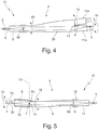
- Fig. 4 shows a beam splitter 31 according to the combined first and second deflection and torsion principle.
- the light beam 5 supplied in the input optical waveguide 2 is transmitted via a deflection (29) of the beam propagation element 26 about the axis 30 either into the upper (11a) or, as in FIG Fig. 4 shown directed into the lower GRIN focusing lens 11b.
- a deflection (10) of the beam propagation element 26 and / or the downstream GRIN focusing lenses 11a, 11b about the axis 14 the light beam 5 within the respective GRIN focusing lens 11a, 11b either downwards or, as in Fig. 4 shown, directed upwards.
- the beam propagation element 26 is additionally twistable in the torsion direction 16.
- a plurality of output optical waveguides 3 staggered in torsion direction 16 are added, into which the light beam 5 can be directed by respectively twisting the beam propagation element 26, respectively.
- the entire beam guidance in the beam switches 1, 21, 31 thus takes place in each case in a single, monolithic element 6, 26 of highly transparent and performance-suitable material, the light beam 5 the optical waveguides 2, 3a, 3b or the material from which they or their cores are made (mostly quartz glass), does not leave.
- the susceptibility of the beam switch 1, 21, 31 is dramatically reduced against maladjustment by aging and thermal effects and against contamination and damage by dust and other impurities , At the same time coupling loss can be minimized by the elimination of optical interfaces (eg anti-reflection coatings on the otherwise existing transition air / glass).
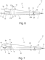
- the in the FIGS. 1 to 4 shown beam switches 1, 21, 31 can also be used for the reverse application, in which a guided in one of several input optical waveguides light beam is to be switched to an output optical waveguide, as in the following with reference to the FIGS. 5 to 7 is described.
- beam splitter 41 shown corresponds to the operated in the reverse direction beam switch 1.
- the beam splitter 41 are the two input optical waveguide 2a, 2a through a GRIN collimating lens 9 to the one end face 7 of the Strahlpropagationselements 6 and an output optical waveguide 3 via a GRIN focusing lens 11 to the other end 8 added.
- the light beam 5 respectively supplied via one of the input optical waveguides 2 a, 2 b can be forwarded by the deflection 10 of the beam propagation element 6 and / or the upstream GRIN collimation lens 9 about the axis 14 into the output optical waveguide 3.
- the desired input optical waveguide can also be selected by twisting (16) the beam propagation element 6 and / or the upstream GRIN collimating lens 9 with a corresponding arrangement of the input optical waveguides.
- beam splitter 51 shown corresponds to the operated in the reverse direction of beam splitter 21.
- the two input optical waveguide 2a, 2a each having a GRIN-collimating lens 9a, 9b at the joining surfaces 27a, 27b of the one end face 27 of the Strahlpropagationselements 26 and an output optical waveguide 3 via a GRIN focusing lens 11 attached to the other end face 28.
- the light beam 5 respectively supplied via one of the input optical waveguides 2 a, 2 b can be deflected by deflecting (29) of the Beam propagation element 26 and / or the upstream GRIN collimating lens 9a, 9b are forwarded around the axis 30 in the output optical waveguide 3.
- the input optical waveguide can also be selected by twisting (16) the beam propagation element 26 and / or the upstream GRIN collimating lens 9a, 9b if the input optical waveguide is arranged accordingly.
- beam splitter 61 corresponds to the operated in the reverse direction beam splitter 31, so that the description of the individual components is omitted.
- the light beam 5 respectively supplied via one of the input optical waveguides 2 can be obtained by twisting (16) the beam propagation element 26 and / or the upstream GRIN collimation lens 9a, 9b and deflecting (10, 29) the beam propagation element 26 and / or the upstream GRIN Collimating lenses 9a, 9b are passed around the axes 14, 30 in the one output optical waveguide 3.
Landscapes
- Physics & Mathematics (AREA)
- General Physics & Mathematics (AREA)
- Optics & Photonics (AREA)
- Mechanical Light Control Or Optical Switches (AREA)
- Optical Couplings Of Light Guides (AREA)
Description
- Die vorliegende Erfindung betrifft sowohl eine optische Strahlweiche mit mindestens einem Eingangslichtwellenleiter, mit mehreren Ausgangslichtwellenleitern und mit einem dazwischen vorgesehenen optischen Schaltelement zum Schalten des in dem mindestens einen Eingangslichtwellenleiter geführten Lichtstrahls auf wahlweise einen der Ausgangslichtwellenleiter als auch eine optische Strahlweiche mit mehreren Eingangslichtwellenleitern, mit mindestens einem
- Ausgangslichtwellenleiter und mit einem dazwischen vorgesehenen optischen Schaltelement zum wahlweisen Schalten eines in einem der
- Eingangslichtwellenleiter geführten Lichtstrahls auf den mindestens einen Ausgangslichtwellenleiter.
- Eine derartige optische Strahlweiche ist beispielsweise durch die
US 4,303,302 bekannt geworden. - Bei dieser aus
US 4,303,302 bekannten optischen Strahlweiche wird das freie Faserende des Eingangslichtwellenleiters mittels eines piezoelektrischen Elements ausgelenkt, so dass das Licht abhängig vom Auslenkwinkel in unterschiedliche Ausgangslichtleiter eingekoppelt wird. Das freie Ende des Eingangslichtwellenleiters und das piezoelektrische Elements bilden zusammen ein optisches Schaltelement. Allerdings führt der zwischen Eingangs- und Ausgangslichtleiter vorhandene Luftspalt zu folgenden Nachteilen: - Anfälligkeit der Strahlweiche gegen Dejustage durch Alterung und thermische Effekte;
- Anfälligkeit der Strahlweiche gegen Verschmutzung und Beschädigung durch Staub und andere Verunreinigungen;
- Koppelverluste durch optische Grenzflächen (z.B. Antireflex-Beschichtungen am Übergang Luft/Lichtleiter).
- Demgegenüber ist es die Aufgabe der vorliegenden Erfindung, bei einer optischen Strahlweiche der jeweils eingangs genannten Art die Freistrahlpropagation in Luft beim Schalten zwischen den mehreren Ausgangs- bzw. Eingangslichtwellenleitern zu vermeiden.
US 4 239 330 A offenbart eine optische Strahlweiche mit einem Eingangslichtwellenleiter, mehreren Ausgangslichtwellenleitern und einem dazwischen vorgesehenen optischen Schaltelement zum Schalten des in dem Eingangslichtwellenleiter geführten Lichtstrahls auf wahlweise einen der Ausgangslichtwellenleiter. Das Schaltelement besteht aus zwei Elementen mit graduell variierendem Brechungsindex (GRIN-Linsen), die gegeneinander drehbar sind, und einem dazwischen befindlichen Gel. - Die Aufgabe wird in einem ersten Aspekt der Erfindung gelöst durch eine optische Strahlweiche mit den Merkmalen von Anspruch 1. Erfindungsgemäß sind der mindestens eine Eingangslichtwellenleiter (Eingangsfaser) an einem Ende und die mehreren Ausgangslichtwellenleiter (Ausgangsfasern) am gegenüberliegenden Ende des Strahlpropagationselements angefügt. Das Umschalten zwischen den Ausgangslichtwellenleitern wird durch gezieltes Auslenken und/oder Tordieren des Strahlpropagationselements und/oder einer nachgeschalteten Fokussierungsoptik erreicht. Basierend auf dieser Grundidee werden erfindungsgemäß drei alternative Ausführungsformen vorgeschlagen, die sich durch die Art der Einkopplung in die Ausgangswellenleiter unterscheiden: Die erste Ausführungsform, im Folgenden als erstes Auslenkungsprinzip bezeichnet, verwendet eine gemeinsame Fokussieroptik für alle Ausgangswellenleiter (z.B. in Form eines GRIN-Faserstücks) für die wahlweise Einkopplung in den jeweiligen Ausgangswellenleiter, während die zweite Ausführungsform, im Folgenden als zweites Auslenkungsprinzip bezeichnet, für jeden Ausgangswellenleiter eine separate Fokussieroptik verwendet. Die dritte Ausführungsform, im Folgenden als Torsionsprinzip bezeichnet, kann sowohl eine gemeinsame als auch für jeden Ausgangswellenleiter eine separate Fokussieroptik verwenden. Für die drei Prinzipien ergeben sich - wie im Folgenden näher beschrieben - unterschiedliche Auslegungen des flexiblen Strahlpropagationselements und verschiedene geometrische Anordnungen für die Ausgangswellenleiter. Vorstellbar ist in diesem Zusammenhang auch eine Kombination der alternativen Prinzipien.
- Bei der optischen Strahlweiche nach dem ersten Auslenkungsprinzip werden erfindungsgemäß der Eingangslichtwellenleiter (Eingangsfaser) an einem Ende und die mehreren Ausgangslichtwellenleiter (Ausgangsfasern) am gegenüberliegenden Ende des Strahlpropagationselements angefügt. Dabei werden die Ausgangslichtwellenleiter näherungsweise parallel zueinander und rechtwinklig zur Stirnseite des Strahlpropagationselements angefügt, um eine geradlinige Strahlführung zu erzielen. Das Umschalten zwischen den Ausgangslichtwellenleitern, d.h. die Auswahl des jeweils gewünschten Ausgangslichtwellenleiters, wird durch gezieltes Auslenken der an die Ausgangslichtwellenleiter angefügten Stirnseite des Strahlpropagationselements und/oder einer nachgeschalteten Fokussierungsoptik um eine oder mehrere Achsen erreicht, welche vorzugsweise im Bereich desjenigen Endes des Strahlpropagationselements vorgesehen sind, an dem die mehreren Ausgangslichtwellenleiter vorgesehen sind.
- Bei der optischen Strahlweiche nach dem zweiten Auslenkungsprinzip werden erfindungsgemäß die Ausgangslichtwellenleiter unter einem bestimmten Winkel (dem jeweiligen Biegewinkel) zur Achse des Strahlpropagationselements angefügt, um eine geradlinige Strahlführung zu erzielen. Das Umschalten zwischen den Ausgangslichtwellenleitern, d.h. die Auswahl des jeweils gewünschten Ausgangslichtwellenleiters, wird durch gezieltes Auslenken des Strahlpropagationselements und/oder einer nachgeschalteten Fokussierungsoptik um eine oder mehrere Achsen erreicht, welche vorzugsweise im Bereich desjenigen Endes des Strahlpropagationselements vorgesehen sind, an dem der mindestens eine Eingangslichtwellenleiter vorgesehen ist. Zusätzlich kann das Strahlpropagationselement der Strahlweiche nach dem zweiten Auslenkungsprinzip einen bevorzugt im Bereich der zumindest einen Achse befindlichen, einseitig verjüngten,Durchmesser aufweisen, damit beim Auslenken des Strahlpropagationselements die kritischen Materialspannungen und die biegeinduzierte Doppelbrechung, die sich negativ auf Polarisationserhaltung und Koppeleffizienz der Strahlweiche auswirken können, minimiert werden. Der Durchmesser des Strahlpropagationselements an der Ausgangsseite ist dabei gegenüber dem Durchmesser auf der Eingangsseite vergrößert. Die Verjüngung des Strahlpropagationselements wird entweder durch Tapern (Ausziehen eines Glaszylinders mit axial variablem Durchmesser nach der Bearbeitung durch gezieltes lokales Erwärmen über die Erweichungstemperatur und kontrolliertes axiales Verfahren der Zylinderenden) oder durch gezieltes Schleifen erzeugt.
- Bei der optischen Strahlweiche nach dem Torsionsprinzip werden die Ausgangslichtwellenleiter erfindungsgemäß in Torsionsrichtung, also kreisförmig, angeordnet. Dies kann sowohl konzentrisch um die optische Achse des Strahlpropagationselements als auch exzentrisch erfolgen. Bei konzentrischer Anordnung wird der Strahl des Eingangslichtwellenleiters nach dem ersten oder zweiten Auslenkungsprinzip auf einen der Ausgangslichtwellenleiter gerichtet, wobei die Ausgangslichtwellenleiter gemäß des jeweils angewendeten ersten oder zweiten Auslenkungsprinzips an das Strahlpropagationselement angefügt sind. Bei exzentrischer Anordnung sind die Ausgangslichtwellenleiter näherungsweise parallel zueinander und rechtwinklig zur Stirnseite des Strahlpropagationselements angefügt, um eine geradlinige Strahlführung zu erzielen. Durch die exzentrische Anordnung der Ausgangslichtwellenleiter wird insbesondere ein vorheriges Auslenken zur Einkopplung des Strahls in einen der Ausgangswellenleiter vermieden. Das Umschalten zwischen den Ausgangslichtwellenleitern, d.h. die Auswahl des jeweils gewünschten Ausgangslichtwellenleiters - ausgehend von einem Ausgangslichtwellenleiter -, wird durch gezieltes Tordieren des Strahlpropagationselementes und/oder einer nachgeschalteten Fokussierungsoptik erreicht.
- Vorzugsweise sind der mindestens eine Eingangslichtwellenleiter über ein Kollimationselement an die eine Stirnseite und die Ausgangslichtwellenleiter über ein gemeinsames bzw. über jeweils ein separates Fokussierungselement an die andere Stirnseite des Strahlpropagationselements angefügt, und zwar insbesondere durch Spleißen. Besonders bevorzugt sind die Kollimations- und Fokussierungselemente durch Gradientindex-Faserstücke mit parabolischem Brechzahlprofil gebildet, die auch als GRIN-Linsen bezeichnet werden. Das Anfügen der mehreren Ausgangswellenleiter an ein Fokussierungselement kann beispielsweise durch einen direkten Spleiß der Ausgangswellenleiter an das Fokussierungselement, durch das Spleißen der in einer Mehrfachkapillare fixierten Ausgangswellenleiter mit dem Fokussierungselement oder durch das Spleißen einer Mehrkernfaser mit dem Fokussierungselement erfolgen.
- Die gesamte Freistrahlpropagation findet somit in einem einzelnen, monolithischen Element aus hochtransparentem und leistungstauglichem Material (typischerweise Quarzglas) statt, ohne dass der geführte Lichtstrahl die Lichtwellenleiter bzw. das Material, aus dem sie bzw. ihre Kerne gefertigt sind (meist Quarzglas), verlassen muss. Durch den Wegfall von diskreten optischen Elementen (Linsen, Spiegel etc.) und den kompakten, monolithischen Aufbau der erfindungsgemäßen optischen Strahlweiche wird die Anfälligkeit der Strahlweiche gegen Dejustagen durch Alterung und thermische Effekte und gegen Verschmutzung und Beschädigung durch Staub und andere Verunreinigungen drastisch reduziert. Gleichzeitig können durch den Wegfall von optischen Grenzflächen (z.B. Antireflex-Beschichtungen am ansonsten vorhandenen Übergang Luft/Glas) Koppelverluste minimiert werden.
- Das Fügen des Strahlpropagationselements mit den Fokussierungs- bzw. Kollimationselementen erfolgt vorzugsweise mittels Stoßkontaktierung (so genannter "optischer Kontakt") oder alternativ mittels Spleißen. Bei der Stoßkontaktierung werden das Strahlpropagationselement und ein Fokussierungs- bzw. Kollimationselement in einer passgenauen Führung unter Berücksichtigung der Hertzschen Pressung aufeinander gepresst, wobei ein spaltfreier mechanischer und optischer Kontakt im Bereich der Strahlführung entsteht. Dieser Kontakt wird vorzugsweise mit dünnflüssigem Klebemittel in der Führung fixiert, wobei der Klebstoff nicht in den Bereich der Strahlführung eindringen sollte, da dies die Leistungstauglichkeit der Fügestelle beeinträchtigen würde. Bei einer Strahlweiche nach dem zweiten Auslenkungsprinzip können zum Fügen des Strahlpropagationselements mit den Fokussierungselementen auch Strahlpropagationselemente mit angeschrägten Fügeflächen verwendet werden.
- Das Strahlpropagationselement und die Fokussierungselemente sind entweder unmittelbar oder mithilfe von Zwischenelementen aneinander angefügt. Im ersten Fall können angeschrägte Fügeflächen zur gegenseitigen Anfügung zwischen den Ausgangslichtwellenleitern und den Fokussierungselementen sowie zwischen dem Strahlpropagationselement und den Fokussierungselementen vorgesehen sein. Im zweiten Fall kann zwischen dem Strahlpropagationselement und den Fokussierungselementen jeweils ein separates Strahlpropagationszwischenelement eingefügt sein, in dem sich der Lichtstrahl frei ausbreitet. Das Strahtpropagationszwischenelement kann ein- oder beidseitig abgeschrägte Fügeflächen zur Anfügung des Strahlpropagationselements und der Fokussierungselemente aufweisen.
- Die optischen Strahlweichen nach dem ersten und zweiten Auslenkungs- sowie dem Torsionsprinzip umfassen erfindungsgemäß jeweils auch eine entsprechende mechanische Auslenk- bzw. Torsionsvorrichtung. Diese mechanische Auslenk- bzw. Torsionsvorrichtung kann dabei eine Aufnahme für die optische Strahlweiche sein, die die für das jeweilige Schaltprinzip benötigte Schaltbewegung ausführt. Als Antriebe für die Schaltbewegung können beispielsweise elektromagnetische Linear- oder Drehantriebe, piezoelektrische Aktuatoren, pneumatische Aktuatoren oder auch Präzisionsmotoren dienen.
- Besonders einfach gestaltet sich die Strahlweiche, wenn zwischen den - in einer Ebene angeordneten - Ausgangslichtwellenleitern mit Hilfe einer (translatorischen oder rotatorischen) eindimensionalen Bewegung ausgewählt werden kann. Allerdings begrenzt dies aufgrund der im flexiblen Strahlpropagationselement und/oder in einer nachgeschalteten Fokussierungsoptik auftretenden und mit der Auslenkung zunehmenden mechanischen Spannungen die Anzahl der Ausgangslichtwellenleiter. Eine weitere Erhöhung der Anzahl der Ausgangslichtwellenleiter kann durch Verwendung einer Bewegung in zwei Achsen und einer jeweils rechtwinklig zu den beiden Achsen zweidimensionalen Anordnung der Ausgangslichtwellenleiter erzielt werden.
- Das erste Auslenkungsprinzip weist gegenüber dem zweiten Auslenkungsprinzip eine Reihe von Vorteilen auf; insbesondere wird - unabhängig von der Zahl der Ausgangslichtwellenleiter - nur ein Fokussierungselement benötigt. Weiterhin erleichtert die parallele Ausrichtung der Ausgangslichtwellenleiter deren Führung - etwa in einer gemeinsamen Mehrfachkapillare. Besonders günstig ist die Ausführungsform mit einer Multikernfaser anstelle von mehreren diskreten Ausgangslichtwellenleitern; hier können die Wellenleiter sehr dicht nebeneinander angeordnet werden, wodurch einerseits die erforderlichen Bewegungen und Kräfte minimiert werden. Andererseits besteht dadurch auch die Möglichkeit, sehr viele Ausgangswellenleiter in einer Strahlweiche zu integrieren. Bei gleicher Anzahl von Ausgangslichtwellenleitern sind beim ersten Auslenkungsprinzip die mechanischen Spannungen und die Doppelbrechung im Strahlpropagationselement typischerweise geringer als bei einer vergleichbaren Strahlweiche nach dem zweiten Auslenkungsprinzip.
- Die oben genannte Aufgabe wird in einem zweiten Aspekt der Erfindung auch gelöst durch eine optische Strahlweiche mit den Merkmalen von Anspruch 4. Erfindungsgemäß sind die mehreren Eingangslichtwellenleiter (Eingangsfasern) an einem Ende und der mindestens eine Ausgangslichtwellenleiter (Ausgangsfaser) am gegenüberliegenden Ende des Strahlpropagationselements angefügt. Das Durchschalten eines der Eingangslichtwellenleiter auf den Ausgangslichtwellenleiter, d.h. das Auswählen des gewünschten Eingangslichtwellenleiters, wird durch gezieltes Auslenken und/oder Tordieren des Strahlpropagationselements und/oder einer vorgeschalteten Kollimationsoptik erreicht.
- Basierend auf dieser Grundidee werden erfindungsgemäß auch hier drei alternative Ausführungsformen vorgeschlagen, die sich durch die Art der Einkopplung in das Strahlpropagationselement unterscheiden: Die erste Ausführungsform, im Folgenden als erstes Auslenkungsprinzip bezeichnet, verwendet eine gemeinsame Kollimationsoptik für alle Eingangswellenleiter (z.B. in Form eines GRIN-Faserstücks) für die Einkopplung in das Strahlpropagationselement, während die zweite Ausführungsform, im Folgenden als zweites Auslenkungsprinzip bezeichnet, für jeden Eingangswellenleiter eine separate Kollimationsoptik verwendet. Die dritte Ausführungsform, im Folgenden als Torsionsprinzip bezeichnet, kann sowohl eine gemeinsame als auch für jeden Eingangswellenleiter eine separate Kollimationsoptik verwenden. Für die drei Prinzipien ergeben sich - wie im Folgenden näher beschrieben - unterschiedliche Auslegungen des flexiblen Strahlpropagationselements und verschiedene geometrische Anordnungen für die Eingangswellenleiter. Vorstellbar ist in diesem Zusammenhang auch eine Kombination der alternativen Prinzipien.
- Bei der optischen Strahlweiche nach dem ersten Auslenkungsprinzip werden erfindungsgemäß die Eingangslichtwellenleiter (Eingangsfasern) an einem Ende und der Ausgangslichtwellenleiter (Ausgangsfaser) am gegenüberliegenden Ende des Strahlpropagationselements angefügt. Dabei werden die Eingangslichtwellenleiter näherungsweise parallel zueinander und rechtwinklig zur Stirnseite des Strahlpropagationselements angefügt, um eine geradlinige Strahlführung zu erzielen. Das Umschalten zwischen den Eingangslichtwellenleitern, d.h. die Auswahl des jeweils gewünschten Eingangslichtwellenleiters, wird durch gezieltes Biegen bzw. Drehen der an die Eingangslichtwellenleiter angefügten Stirnseite des Strahlpropagationselements und/oder einer vorgeschalteten Kollimationsoptik um eine oder mehrere Achsen erreicht, welche vorzugsweise im Bereich desjenigen Endes des Strahlpropagationselements vorgesehen sind, an dem die mehreren Eingangslichtwellenleiter vorgesehen sind.
- Bei der optischen Strahlweiche nach dem zweiten Auslenkungsprinzip werden erfindungsgemäß die Eingangslichtwellenleiter unter einem bestimmten Winkel (dem jeweiligen Biegewinkel) zur optischen Achse des Strahlpropagationselements angefügt, um eine geradlinige Strahlführung zu erzielen. Das Umschalten zwischen den Eingangslichtwellenleitern, d.h. die Auswahl des jeweils gewünschten Eingangslichtwellenleiters, wird durch gezieltes Auslenken des Strahlpropagationselements und/oder einer vorgeschalteten Kollimationsoptik um eine oder mehrere Achsen erreicht, welche vorzugsweise im Bereich desjenigen Endes Endes des Strahlpropagationselements vorgesehen sind, an dem der mindestens eine Ausgangslichtwellenleiter vorgesehen ist.
- Bei der optischen Strahlweiche nach dem Torsionsprinzip werden die Eingangslichtwellenleiter erfindungsgemäß in Torsionsrichtung, also kreisförmig, angeordnet. Dies kann sowohl konzentrisch um die optische Achse des Strahlpropagationselements als auch exzentrisch erfolgen. Das Umschalten zwischen den Eingangslichtwellenleitern, d.h. die Auswahl des jeweils gewünschten Eingangslichtwellenleiters, wird durch gezieltes Tordieren des Strahlpropagationselementes erreicht.
- Vorzugsweise sind die Eingangslichtwellenleiter über ein gemeinsames bzw. über jeweils ein separates Kollimationselement an die eine Stirnseite und der Ausgangslichtwellenleiter über ein Fokussierungselement an die andere Stirnseite des Strahlpropagationselements angefügt, und zwar insbesondere durch Spleißen. Besonders bevorzugt sind die Kollimations- und Fokussierungselemente durch Gradientindex-Faserstücke mit parabolischem Brechzahlprofil gebildet, die auch als GRIN-Linsen bezeichnet werden. Das Anfügen der mehreren Eingangswellenleiter an ein Kollimationselement kann beispielsweise durch einen direkten Spleiß der Eingangswellenleiter an das Kollimationselement, durch das Spleißen der in einer Mehrfachkapillare fixierten Eingangswellenleiter mit dem Kollimationselement oder durch das Spleißen einer Mehrkernfaser mit dem Kollimationselement erfolgen.
- Weitere Vorteile der Erfindung ergeben sich aus den Ansprüchen, der Beschreibung und der Zeichnung. Ebenso können die vorstehend genannten und die noch weiter aufgeführten Merkmale je für sich oder zu mehreren in beliebigen Kombinationen Verwendung finden. Die gezeigten und beschriebenen Ausführungsformen sind nicht als abschließende Aufzählung zu verstehen, sondern haben vielmehr beispielhaften Charakter für die Schilderung der Erfindung.
- Es zeigen:
- Fign. 1a, 1b
- ein Ausführungsbeispiel der erfindungsgemäßen optischen Strahlweiche mit einer Eingangsfaser und mit zwei Ausgangsfasern nach dem ersten Auslenkungsprinzip in einer ersten Weichenposition (
Fig. 1a ) und in einer zweiten Weichenposition (Fig. 1b ); - Fign. 2a-2d
- mögliche Geometrien von Mehrfachkapillaren bzw. Mehrkernfasern für die Ausgangsfasern der in
Fig. 1 gezeigten erfindungsgemäßen optischen Strahlweiche; - Fign. 3a, 3b
- ein Ausführungsbeispiel der erfindungsgemäßen optischen Strahlweiche mit einer Eingangsfaser und mit zwei Ausgangsfasern nach dem zweiten Auslenkungsprinzip in einer ersten Weichenposition (
Fig. 3a ) und in einer zweiten Weichenposition (Fig. 3b ); - Fig. 4
- ein Ausführungsbeispiel der erfindungsgemäßen optischen Strahlweiche mit einer Eingangsfaser und mit mehreren Ausgangsfasern nach dem kombinierten ersten und zweiten Auslenkungs- und Torsionsprinzip; und
- Fign. 5 bis 7
- Ausführungsbeispiele der erfindungsgemäßen optischen Strahlweiche mit zwei bzw. mehreren Eingangsfasern und einer Ausgangsfaser nach dem ersten und zweiten Auslenkungs- sowie dem Torsionsprinzip.
- Die in
Fign. 1 und3 gezeigten optischen Strahlweichen 1, 21 umfassen jeweils einen Eingangslichtwellenleiter (z.B. Glasfaser) 2, zwei Ausgangslichtwellenleiter (z.B. Glasfasern) 3a, 3b und ein dazwischen vorgesehenes optisches Schaltelement 4 zum Schalten eines im Eingangslichtwellenleiter 2 zugeführten Lichtstrahls 5 auf wahlweise den einen oder den anderen Ausgangslichtwellenleiter 3a, 3b. Die beiden Strahlweichen 1, 21 unterscheiden sich durch die Art der Einkopplung des Lichtstrahls 5 in die Ausgangslichtwellenleiter 3a, 3b. Die Strahlweiche 1 arbeitet nach dem sogenannten ersten Auslenkungsprinzip und verwendet eine gemeinsame Fokussieroptik für die wahlweise Einkopplung in die Ausgangslichtwellenleiter 3a, 3b, während die Strahlweiche 21 nach dem sogenannten zweiten Auslenkungsprinzip arbeitet und für jeden Ausgangslichtwellenleiter 3a, 3b eine separate Fokussieroptik verwendet. - Bei der in
Fig. 1 gezeigten Strahlweiche 1 nach dem ersten Auslenkungsprinzip ist das optische Schaltelement 4 durch ein quer zu seiner optischen Längsachse elastisch auslenkbares, zylindrisches Strahlpropagationselement 6 mit zwei einander gegenüberliegenden Stirnseiten 7, 8 gebildet, in dem sich der Lichtstrahl 5 frei ausbreitet. Das Strahlpropagationselement 6 besteht aus hochtransparentem und leistungstauglichem Vollmaterial, wie z.B. Quarzglas. - Der Eingangslichtwellenleiter 2 ist über ein Gradientindex-Kollimationsfaserstück 9 mit parabolischem Brechzahlprofil und mit geeigneter Länge (1/4 Pitch) an die Eingangsstirnseite 7 des Strahlpropagationselements 6 durch Spleißen angefügt. Das Gradientindex-Kollimationsfaserstück 9 übernimmt die Funktion einer Kollimationslinse und wird im Folgenden kurz "GRIN-Kollimationslinse" genannt. Die Ausgangslichtwellenleiter 3a, 3b sind in Auslenkrichtung 10 des Strahlpropagationselements 6 nebeneinander angeordnet und über ein Gradientindex-Fokussierungsfaserstück 11 mit parabolischem Brechzahlprofil und mit geeigneter Länge (1/4 Pitch) an die Ausgangsstirnseite 8 des Strahlpropagationselements 6 durch Spleißen angefügt. Das Gradientindex-Fokussierungsfaserstück 11 übernimmt die Funktion einer Fokussierlinse und wird im Folgenden kurz "GRIN-Fokussierungslinse" genannt. Die Ausgangslichtwellenleiter 3a, 3b werden näherungsweise parallel zueinander und rechtwinklig zur Ausgangsstirnseite 8 des Strahlpropagationselements 6 angefügt, um eine geradlinige Strahlführung zu erzielen.
- Die GRIN-Kollimationslinse 9 und das zugehörige Ende 6a des Strahlpropagationselements 6 sind in einer Haltehülse 12, die ortsfest fixiert ist, gehalten bzw. darin eingeklebt. Die GRIN-Fokussierungslinse 11 und das zugehörige Ende 6b des Strahlpropagationselements 6 sind in einer Führungshülse 13 gehalten bzw. darin eingeklebt, die um eine im Bereich des Endes 6b des Strahlpropagationselements 6 vorgesehene Achse 14 in Auslenkrichtung 10 drehbar gelagert ist. Die Achse 14 liegt vorzugsweise innerhalb des von der Führungshülse 13 gehaltenen Endes 6b des Strahlpropagationselements 6 und liegt in
Fig. 1 in der Ebene der Ausgangsstirnseite 8 des Strahlpropagationselements 6. - Das Umschalten des im Eingangslichtwellenleiter 2 zugeführten Lichtstrahls 5 zwischen den Ausgangslichtwellenleitern 3a, 3b wird durch gezieltes Auslenken der Führungshülse 13 und folglich des Endes 6b des Strahlpropagationselements 6 und/oder der nachgeschalteten GRIN-Fokussierungslinse 11 um die Achse 14 erreicht. In der in
Fig. 1 a gezeigten ersten Weichenposition der Strahlweiche 1 wird der Lichtstrahl 5 in den Ausgangslichtwellenleiter 3b und in der inFig. 1b gezeigten zweiten Weichenposition in den Ausgangslichtwellenleiter 3a eingekoppelt. Das Verhältnis von Länge und Dicke des Strahlpropagationselements 6 und/oder der nachgeschalteten GRIN-Fokussierungslinse 11 ist dabei ausreichend hoch, um eine Beschädigung des Strahlpropagationselements 6 und/oder der nachgeschalteten GRIN-Fokussierungslinse 11 auch bei häufigem und dauerhaftem Auslenken sicher zu vermeiden. - Das Anfügen der beiden Ausgangswellenleiter 3a, 3b oder von mehreren Ausgangswellenleitern an die GRIN-Fokussierungslinse 11 kann entweder durch einen direkten Spleiß der Ausgangswellenleiter 3a, 3b an die GRIN-Fokussierungslinse 11, durch das Spleißen der in einer Mehrfachkapillare fixierten Ausgangswellenleiter 3a, 3b mit der GRIN-Fokussierungslinse 11 oder durch das Spleißen einer Mehrkernfaser mit der GRIN-Fokussierungslinse 11 erfolgen. Die parallele Ausrichtung der Ausgangslichtwellenleiter 3a, 3b erleichtert deren Führung - etwa in einer gemeinsamen Mehrfachkapillare. Besonders günstig ist die Ausführungsform mit einer Multikernfaser anstelle von mehreren diskreten Ausgangslichtwellenleitern.
- Eine weitere Erhöhung der Anzahl der Ausgangslichtwellenleiter kann durch Verwendung einer Bewegung in zwei Achsen, wie in
Fig. 1 durch die weitere Achse 15 angedeutet ist, und einer jeweils rechtwinklig zu den beiden Achsen 14, 15 zweidimensionalen Anordnung der Ausgangslichtwellenleiter erzielt werden. Alternativ oder, wie inFig. 1 gezeigt, zusätzlich zu der Auslenkung um die Achsen 14, 15 kann das Strahlpropagationselement 6 und/oder die nachgeschaltete GRIN-Fokussierungslinse 11 auch um seine Längsachse tordierbar sein, wodurch das ausgangsseitige Ende 6b des Strahlpropagationselements 6 samt GRIN-Fokussierungslinse 11 gegenüber dem eingangsseitigen Ende 6a in Torsionsrichtung 16 verdrehbar ist. Bei diesem Torsionsprinzip sind die Ausgangslichtwellenleiter in Torsionsrichtung 16 versetzt angeordnet, und das Umschalten zwischen den Ausgangslichtwellenleitern, d.h. die Auswahl des jeweils gewünschten Ausgangslichtwellenleiters, wird durch gezieltes Tordieren des Strahlpropagationselementes 6 und/oder der nachgeschalteten GRIN-Fokussierungslinse 11 erreicht. -
Fign. 2a bis 2c zeigen mögliche Geometrien einer als Mehrkernfaser oder als Faser mit Mehrfachkapillaren ausgebildeten Ausgangsfaser 17 für eine Strahlweiche 1 nach dem ersten Auslenkungsprinzip. InFig. 2a und 2c sind zwei bzw. drei Kernfasern oder Kapillaren 3 der Ausgangsfasern 17 in einer Linie für eine Auslenkung des Strahlpropagationselements 6 und/oder der nachgeschalteten GRIN-Fokussierungslinse 11 um eine einzige Achse 14 angeordnet. InFig. 2b sind fünf Kernfasern oder Kapillaren 3 der Ausgangsfasern 17 zweidimensional für eine Auslenkung des Strahlpropagationselements 6 und/oder der nachgeschalteten GRIN-Fokussierungslinse 11 um zwei Achsen 14, 15 angeordnet.Fign. 2d zeigt eine weitere mögliche Geometrie einer als Mehrkernfaser oder als Faser mit Mehrfachkapillaren ausgebildeten Ausgangsfaser 17 für eine Strahlweiche 1 nach dem kombinierten ersten Auslenkungs- und Torsionsprinzip. Acht Kapillaren 31 bis 38 der Ausgangsfaser 17 sind konzentrisch um die Faserachse (Torsionsachse) herum angeordnet. Die Kapillaren 31, 33, 35, 37 werden durch eine Auslenkung des Strahlpropagationselements 6 und/oder der nachgeschalteten GRIN-Fokussierungslinse 11 um die Achsen 14, 15 ausgewählt, während die übrigen Kapillare 32, 34, 36, 37 durch eine Kombination aus einer Auslenkung um eine der beiden Achsen 14, 15 und einer Torsionsbewegung um 45° ausgewählt werden können. Selbstverständlich können die acht Kapillaren 31 bis 38 auch allein durch gezieltes Tordieren oder eine zweiachsige Auslenkung um die Achsen 14, 15 des Strahlpropagationselementes 6 und/oder der nachgeschalteten GRIN-Fokussierungslinse 11 ausgewählt werden. - Bei der in
Fig. 3 gezeigten Strahlweiche 21 nach dem zweiten Auslenkungsprinzip ist das optische Schaltelement 4 durch ein quer zu seiner optischen Längsachse elastisch biegsames, konisches Strahlpropagationselement 26 aus hochtransparentem und leistungstauglichem Vollmaterial, wie z.B. Quarzglas, gebildet, in dem sich der Lichtstrahl 5 frei ausbreitet. Das Strahlpropagationselement 26 verjüngt sich einseitig zur Eingangsstirnseite 27, d.h., der Durchmesser des Strahlpropagationselements 26 an der Ausgangsstirnseite 28 ist gegenüber dem Durchmesser auf der Eingangsstirnseite 27 vergrößert, damit beim Auslenken des Strahlpropagationselements 26 um die Achse 30 in Auslenkrichtung 29 die kritischen Materialspannungen und die biegeinduzierte Doppelbrechung, die sich negativ auf Polarisationserhaltung und Koppeleffizienz der Strahlweiche 21 auswirken können, minimiert werden. Die Verjüngung des Strahlpropagationselements 26 kann durch Tapern oder durch gezieltes Schleifen erzeugt werden. - Der Eingangslichtwellenleiter 2 ist über die GRIN-Kollimationslinse 9 an die Eingangsstirnseite 27 des Strahlpropagationselements 26 durch Spleißen angefügt. Das Strahlpropagationselement 26 weist an seiner Ausgangsstirnseite 28 zwei individuell angeschrägte Fügeflächen 28a, 28b für zwei GRIN-Fokussierungslinsen 11a, 11b auf, an denen die in Auslenkrichtung 29 nebeneinander angeordneten Ausgangslichtwellenleiter 3a, 3b jeweils rechtwinklig angespleißt sind. Die GRIN-Kollimationslinse 9 und das zugehörige Ende 26a des Strahlpropagationselements 26 sind in der ortsfest fixierten Haltehülse 12 gehalten bzw. darin eingeklebt. Das andere, freie Ende 26b des Strahlpropagationselements 26 ist nicht eingespannt und kann folglich um die innerhalb der Haltehülse 12 befindliche Achse 30 in Auslenkrichtung 29 ausgelenkt werden. Die Ausgangslichtwellenleiter 3a, 3b sind unter einem bestimmten Winkel (dem jeweiligen Auslenkwinkel) zur optischen Achse des Strahlpropagationselements 26 angeordnet, um eine geradlinige Strahlführung des Lichtstrahls 5 zu erzielen.
- Das Umschalten des im Eingangslichtwellenleiter 2 zugeführten Lichtstrahls 5 zwischen den Ausgangslichtwellenleitern 3a, 3b wird durch gezieltes Auslenken des freien Endes 26b des Strahlpropagationselements 26 in Auslenkrichtung 29 erreicht. In der in
Fig. 3a gezeigten ersten Weichenposition der Strahlweiche 21 wird der Lichtstrahl 5 in den Ausgangslichtwellenleiter 3b und in der inFig. 3b gezeigten zweiten Weichenposition in den Ausgangslichtwellenleiter 3a eingekoppelt. Das Verhältnis von Länge und Dicke des Strahlpropagationselements 26 ist dabei ausreichend hoch, um eine Beschädigung des Strahlpropagationselements 26 auch bei häufigem und dauerhaftem Biegen sicher zu vermeiden. - Um das Auslenken zu erleichtern, kann das Strahlpropagationselement 26 einen im Querschnitt reduzierten dünneren Mittelabschnitt (nicht gezeigt) aufweisen. Bei geeigneter Auslegung des dünneren Mittelabschnitts kann die Biegung des Strahlpropagationselements 26 auf den dünneren Mittelabschnitt eingeschränkt werden. Die Verwendung des dünneren Mittelabschnitts kann die biegeinduzierte Doppelbrechung in dem Strahlpropagationselement 26, die sich negativ auf Polarisationserhaltung und Koppeleffizienz der optischen Strahlweiche auswirken kann, reduzieren.
- Wie in
Fig. 3 lediglich angedeutet, kann auch bei der Strahlweiche 21 nach dem zweiten Auslenkungsprinzip das Strahlpropagationselement 26 zusätzlich in Torsionsrichtung 16 tordierbar gelagert sein, wobei in diesem Fall an jeder GRIN-Fokussierungslinse 11a, 11b mehrere in Torsionsrichtung 16 versetzt angeordnete Ausgangslichtwellenleiter (nicht gezeigt) angefügt sind. -
Fig. 4 zeigt eine Strahlweiche 31 nach dem kombinierten ersten und zweiten Auslenkungs- und Torsionsprinzip. Der im Eingangslichtwellenleiter 2 zugeführte Lichtstrahl 5 wird über eine Auslenkung (29) des Strahlpropagationselements 26 um die Achse 30 entweder in die obere (11a) oder, wie inFig. 4 gezeigt, in die untere GRIN-Fokussierungslinse 11b geleitet. Durch eine Auslenkung (10) des Strahlpropagationselements 26 und/oder der nachgeschalteten GRIN-Fokussierungslinsen 11a, 11b um die Achse 14 wird der Lichtstrahl 5 innerhalb der jeweiligen GRIN-Fokussierungslinse 11a, 11b entweder nach unten oder, wie inFig. 4 gezeigt, nach oben geleitet. Das Strahlpropagationselement 26 ist zusätzlich in Torsionsrichtung 16 tordierbar. An jeder GRIN-Fokussierungslinse 11a, 11b sind mehrere in Torsionsrichtung 16 versetzt angeordnete Ausgangslichtwellenleiter 3 (nicht gezeigt) angefügt, in die der Lichtstrahl 5 jeweils durch entsprechendes Tordieren des Strahlpropagationselements 26 geleitet werden kann. - Die gesamte Strahlführung in den Strahlweichen 1, 21, 31 findet somit jeweils in einem einzelnen, monolithischen Element 6, 26 aus hochtransparentem und leistungstauglichem Material statt, wobei der Lichtstrahl 5 die Lichtwellenleiter 2, 3a, 3b bzw. das Material, aus dem sie bzw. ihre Kerne gefertigt sind (meist Quarzglas), nicht verlässt. Durch den Wegfall von separat justierbaren optischen Elementen (Linsen, Spiegel etc.) und den kompakten, monolithischen Aufbau wird die Anfälligkeit der Strahlweiche 1, 21, 31 gegen Dejustagen durch Alterung und thermische Effekte und gegen Verschmutzung und Beschädigung durch Staub und andere Verunreinigungen drastisch reduziert. Gleichzeitig können durch den Wegfall von optischen Grenzflächen (z.B. Antireflex-Beschichtungen am ansonsten vorhandenen Übergang Luft/Glas) Koppelverluste minimiert werden.
- Die in den
Fign. 1 bis 4 gezeigten Strahlweichen 1, 21, 31 können auch für den umgekehrten Anwendungsfall eingesetzt werden, bei dem ein in einem von mehreren Eingangslichtwellenleitern geführter Lichtstrahl auf einen Ausgangslichtwellenleiter geschaltet werden soll, wie im Folgenden mit Bezug auf dieFign. 5 bis 7 beschrieben wird. - Die in
Fig. 5 gezeigte Strahlweiche 41 entspricht der in umgekehrter Richtung betriebenen Strahlweiche 1. Bei der Strahlweiche 41 sind die beiden Eingangslichtwellenleiter 2a, 2a über eine GRIN-Kollimationslinse 9 an die eine Stirnseite 7 des Strahlpropagationselements 6 und der eine Ausgangslichtwellenleiter 3 über eine GRIN-Fokussierungslinse 11 an die andere Stirnseite 8 angefügt. Der über einen der Eingangslichtwellenleiter 2a, 2b jeweils zugeführte Lichtstrahl 5 kann durch Auslenken 10 des Strahlpropagationselements 6 und/oder der vorgeschalteten GRIN-Kollimationslinse 9 um die Achse 14 in den Ausgangslichtwellenleiter 3 weitergeleitet werden. Analog zur Strahlweiche 1 kann bei entsprechender Anordnung der Eingangslichtwellenleiter der gewünschte Eingangslichtwellenleiter auch durch Tordieren (16) des Strahlpropagationselements 6 und/oder der vorgeschalteten GRIN-Kollimationslinse 9 ausgewählt werden. - Die in
Fig. 6 gezeigte Strahlweiche 51 entspricht der in umgekehrter Richtung betriebenen Strahlweiche 21. Bei der Strahlweiche 51 sind die beiden Eingangslichtwellenleiter 2a, 2a jeweils über eine GRIN-Kollimationslinse 9a, 9b an die Fügeflächen 27a, 27b der einen Stirnseite 27 des Strahlpropagationselements 26 und der eine Ausgangslichtwellenleiter 3 über eine GRIN-Fokussierungslinse 11 an die andere Stirnseite 28 angefügt. Der über einen der Eingangslichtwellenleiter 2a, 2b jeweils zugeführte Lichtstrahl 5 kann durch Auslenken (29) des Strahlpropagationselements 26 und/oder der vorgeschalteten GRIN-Kollimationslinse 9a, 9b um die Achse 30 in den Ausgangslichtwellenleiter 3 weitergeleitet werden. Analog zur Strahlweiche 21 kann bei entsprechender Anordnung der Eingangslichtwellenleiter der gewünschte Eingangslichtwellenleiter auch durch Tordieren (16) des Strahlpropagationselements 26 und/oder der vorgeschalteten GRIN-Kollimationslinse 9a, 9b ausgewählt werden. - Die in
Fig. 7 gezeigte Strahlweiche 61 entspricht der in umgekehrter Richtung betriebenen Strahlweiche 31, so dass die Beschreibung der einzelnen Komponenten ausgelassen ist. Bei der Strahlweiche 61 kann der über einen der Eingangslichtwellenleiter 2 jeweils zugeführte Lichtstrahl 5 durch Tordieren (16) des Strahlpropagationselements 26 und/oder der vorgeschalteten GRIN-Kollimationslinse 9a, 9b und Auslenken (10, 29) des Strahlpropagationselements 26 und/oder der vorgeschalteten GRIN-Kollimationslinsen 9a, 9b um die Achsen 14, 30 in den einen Ausgangslichtwellenleiter 3 weitergeleitet werden.
Claims (15)
- Optische Strahlweiche (1; 21; 31)
mit mindestens einem Eingangslichtwellenleiter (2),
mit mehreren Ausgangslichtwellenleitern (3, 3a, 3b, 31 bis 38) und
mit einem dazwischen vorgesehenen optischen Schaltelement (4) zum Schalten des in dem mindestens einen Eingangslichtwellenleiter (2) geführten Lichtstrahls (5) auf wahlweise einen der Ausgangslichtwellenleiter (3, 3a, 3b, 31 bis 38), wobei das optische Schaltelement (4) durch ein Strahlpropagationselement (6; 26) mit zwei einander gegenüberliegenden Stirnseiten (7, 8; 27, 28), in dem sich der Lichtstrahl (5) frei ausbreitet, gebildet ist, wobei das Strahlpropagationselement (6; 26) aus einem elastisch biegsamen bzw. tordierbaren, transparenten Vollmaterial gebildet ist, wobei der mindestens eine Eingangslichtwellenleiter (2) unmittelbar oder über eine vorgeschaltete Kollimationsoptik an die eine Stirnseite (7; 27) des Strahlpropagationselements (6; 26) angefügt ist, und wobei die Ausgangslichtwellenleiter (3, 3a, 3b, 31 bis 38) in mindestens einer Auslenkrichtung (10; 29) bzw. in Torsionsrichtung (16) des Strahlpropagationselements (6; 26) nebeneinander angeordnet und unmittelbar oder über eine nachgeschaltete Fokussierungsoptik an die andere Stirnseite (8; 28) des Strahlpropagationselements (6; 26) angefügt sind,
wobei das Strahlpropagationselement (6; 26) und gegebenenfalls die nachgeschaltete Fokussierungsoptik quer zu ihrer optischen Achse auslenkbar und/oder um ihre optische Achse oder parallel dazu tordierbar sind. - Optische Strahlweiche nach Anspruch 1, dadurch gekennzeichnet, dass der mindestens eine Eingangslichtwellenleiter (2) über ein Kollimationselement (9), insbesondere ein Gradientindex-Kollimationsfaserstück, an die eine Stirnseite (7; 27) des Strahlpropagationselements (6; 26) angefügt ist.
- Optische Strahlweiche nach Anspruch 1 oder 2, dadurch gekennzeichnet, dass die Ausgangslichtwellenleiter (3, 3a, 3b, 31 bis 38) über ein gemeinsames Fokussierungselement (11), insbesondere ein Gradientindex-Fokussierungsfaserstück, an die andere Stirnseite (8) des Strahlpropagationselements (6) angefügt sind oder dass die Ausgangslichtwellenleiter (3a, 3b) jeweils über separate Fokussierungselemente (11a, 11b), insbesondere Gradientindex-Fokussierungsfaserstücke, an die andere Stirnseite (28) des Strahlpropagationselements (26) angefügt sind.
- Optische Strahlweiche (41; 51; 61)
mit mehreren Eingangslichtwellenleitern (2, 2a, 2b),
mit mindestens einem Ausgangslichtwellenleiter (3) und
mit einem dazwischen vorgesehenen optischen Schaltelement (4) zum wahlweisen Schalten eines in einem der Eingangslichtwellenleiter (2, 2a, 2b) geführten Lichtstrahls (5) auf den mindestens einen Ausgangslichtwellenleiter (3),
wobei das optische Schaltelement (4) durch ein Strahlpropagationselement (6; 26) mit zwei einander gegenüberliegenden Stirnseiten (7, 8; 27, 28), in dem sich der Lichtstrahl (5) frei ausbreitet, gebildet ist,
wobei das Strahlpropagationselement (6; 26) aus einem festen, aber biegsamen bzw. tordierbaren, transparenten Vollmaterial gebildet ist, wobei die Eingangslichtwellenleiter (2, 2a, 2b) in mindestens einer Auslenkrichtung (10; 29) bzw. in Torsionsrichtung (16) des Strahlpropagationselements (6; 26) nebeneinander angeordnet und unmittelbar oder über eine vorgeschaltete Kollimationsoptik an die eine Stirnseite (7; 27) des Strahlpropagationselements (6; 26) angefügt sind, und
wobei der mindestens eine Ausgangslichtwellenleiter (3) unmittelbar oder über eine nachgeschaltete Fokussierungsoptik an die andere Stirnseite (8; 28) des Strahlpropagationselements (6; 26) angefügt ist,
wobei das optische Schaltelement (6, 26) und gegebenenfalls die vorgeschaltete Kollimationsoptik quer zu ihrer optischen Achse auslenkbar und/oder um ihre optische Achse oder parallel dazu tordierbar sind. - Optische Strahlweiche nach Anspruch 4, dadurch gekennzeichnet, dass die Eingangslichtwellenleiter (2a, 2b) über ein gemeinsames Kollimationselement (9), insbesondere ein Gradientindex-Kollimationsfaserstück, an die eine Stirnseite (7) des Strahlpropagationselements (6) angefügt sind oder dass die Eingangslichtwellenleiter (2a, 2b) jeweils über separate Kollimationselemente (9a, 9b), insbesondere Gradientindex-Kollimationsfaserstücke, an die eine Stirnseite (27) des Strahlpropagationselements (26) angefügt sind.
- Optische Strahlweiche nach einem der Ansprüche 4 bis 5, dadurch gekennzeichnet, dass der mindestens eine Ausgangslichtwellenleiter (3) über ein Fokussierungselement (11), insbesondere ein Gradientindex-Fokussierungsfaserstück, an die andere Stirnseite (8; 28) des Strahlpropagationselements (6; 26) angefügt ist.
- Optische Strahlweiche nach einem der Ansprüche 2 bis 3 und 5 bis 6, dadurch gekennzeichnet, dass die Elemente (9, 9a, 9b, 11, 11a, 11b) jeweils ein parabolisches Brechzahlprofil aufweisen.
- Optische Strahlweiche nach einem der Ansprüche 2 bis 3 und 5 bis 7, dadurch gekennzeichnet, dass die Elemente (9, 9a, 9b, 11, 11a, 11b) an das Strahlpropagationselement (6; 26) und an die Eingangs- und Ausgangslichtwellenleiter (2, 2a, 2b, 3, 3a, 3b, 31 bis 38) durch Spleißen angefügt sind.
- Optische Strahlweiche nach einem der vorhergehenden Ansprüche, dadurch gekennzeichnet, dass das Strahlpropagationselement (6; 26) und/oder die Eingangslichtwellenleiter (2a, 2b) und/oder die Kollimationselemente (9a, 9b) und/oder die Ausgangslichtwellenleiter (3a, 3b) und/oder die Fokussierungsfaserstücke (11a, 11b) angeschrägte Fügeflächen (27, 27b; 28a, 28b) zur gegenseitigen Anfügung aufweisen.
- Optische Strahlweiche nach einem der vorhergehenden Ansprüche, dadurch gekennzeichnet, dass die mehreren Eingangslichtwellenleiter (2a, 2b) bzw. die mehreren Ausgangslichtwellenleiter (3a, 3b) parallel zueinander verlaufen oder zueinander unter einem Winkel angeordnet sind.
- Optische Strahlweiche nach einem der vorhergehenden Ansprüche, dadurch gekennzeichnet, dass das Strahlpropagationselement (6, 26) um mindestens eine Achse (14, 30) auslenkbar gelagert ist und die mehreren Eingangslichtwellenleiter (2a, 2b) bzw. die mehreren Ausgangslichtwellenleiter (3a, 3b) in einer rechtwinklig zur mindestens einen Achse (14; 30) verlaufenden Linie angeordnet sind.
- Optische Strahlweiche nach einem der Ansprüche 1 bis 10, dadurch gekennzeichnet, dass das Strahlpropagationselement (26) um zwei, insbesondere rechtwinklig zueinander verlaufende, Achsen (14, 15) auslenkbar gelagert ist und die mehreren Eingangslichtwellenleiter (2, 2a, 2b) bzw. die mehreren Ausgangslichtwellenleiter (3, 3a, 3b) jeweils rechtwinklig zu den beiden Achsen (14, 15) zweidimensional angeordnet sind.
- Optische Strahlweiche nach einem der vorhergehenden Ansprüche, dadurch gekennzeichnet, dass eine Achse bzw. Achsen (14, 15,-30) im Bereich desjenigen Endes (6a, 26a) des Strahlpropagationselements (6; 26) vorgesehen sind, an dem der mindestens eine Eingangs- bzw. Ausgangslichtwellenleiter (2, 3) vorgesehen ist.
- Optische Strahlweiche nach einem der vorhergehenden Ansprüche, dadurch gekennzeichnet, dass eine Achse bzw. Achsen (14, 15, 30) im Bereich desjenigen Endes (6b, 26b) des Strahlpropagationselements (6; 26) vorgesehen sind, an dem die mehreren Eingangs- bzw. Ausgangslichtwellenleiter (2, 2a, 2b; 3, 3a, 3b) vorgesehen sind,
- Optische Strahlweiche nach einem der vorhergehenden Ansprüche, dadurch gekennzeichnet, dass die mehreren Eingangslichtwellenleiter (2, 2a, 2b) bzw. die mehreren Ausgangslichtwellenleiter (3a, 3b, 31 bis 38) durch die Kapillaren einer Mehrfachkapillarfaser (16) oder durch die Fasern einer Multikernfaser (16) gebildet sind.
Applications Claiming Priority (2)
| Application Number | Priority Date | Filing Date | Title |
|---|---|---|---|
| DE200910027348 DE102009027348A1 (de) | 2009-06-30 | 2009-06-30 | Optische Strahlweiche |
| PCT/DE2010/050033 WO2011000366A1 (de) | 2009-06-30 | 2010-05-27 | Optische strahlweiche |
Publications (2)
| Publication Number | Publication Date |
|---|---|
| EP2449416A1 EP2449416A1 (de) | 2012-05-09 |
| EP2449416B1 true EP2449416B1 (de) | 2017-11-29 |
Family
ID=43016647
Family Applications (1)
| Application Number | Title | Priority Date | Filing Date |
|---|---|---|---|
| EP10727342.7A Active EP2449416B1 (de) | 2009-06-30 | 2010-05-27 | Optische strahlweiche |
Country Status (5)
| Country | Link |
|---|---|
| US (1) | US8934742B2 (de) |
| EP (1) | EP2449416B1 (de) |
| CN (1) | CN102640026B (de) |
| DE (1) | DE102009027348A1 (de) |
| WO (1) | WO2011000366A1 (de) |
Families Citing this family (27)
| Publication number | Priority date | Publication date | Assignee | Title |
|---|---|---|---|---|
| DE102011003686A1 (de) * | 2011-02-07 | 2012-08-09 | Trumpf Laser- Und Systemtechnik Gmbh | Laserbearbeitungsvorrichtung |
| CN106443900B (zh) * | 2012-10-05 | 2019-08-09 | 3M创新有限公司 | 光学连接器 |
| DE102012219074A1 (de) * | 2012-10-19 | 2014-04-24 | Trumpf Werkzeugmaschinen Gmbh + Co. Kg | Laserschneidmaschine und Verfahren zum Schneiden von Werkstücken unterschiedlicher Dicke |
| US11517978B2 (en) | 2012-10-19 | 2022-12-06 | Trumpf Werkzeugmaschinen Gmbh + Co. Kg | Laser cutting machine and method for cutting workpieces of different thicknesses |
| CN105144346B (zh) | 2013-02-21 | 2017-12-15 | 恩耐公司 | 多层结构的激光刻图 |
| US10069271B2 (en) | 2014-06-02 | 2018-09-04 | Nlight, Inc. | Scalable high power fiber laser |
| US10618131B2 (en) | 2014-06-05 | 2020-04-14 | Nlight, Inc. | Laser patterning skew correction |
| US9507982B2 (en) * | 2015-01-06 | 2016-11-29 | Honeywell International Inc. | Line replaceable unit health nodes and methods for determining maintenance actions relating to line replaceable units |
| US9837783B2 (en) | 2015-01-26 | 2017-12-05 | Nlight, Inc. | High-power, single-mode fiber sources |
| US10050404B2 (en) | 2015-03-26 | 2018-08-14 | Nlight, Inc. | Fiber source with cascaded gain stages and/or multimode delivery fiber with low splice loss |
| WO2017008022A1 (en) | 2015-07-08 | 2017-01-12 | Nlight, Inc. | Fiber with depressed central index for increased beam parameter product |
| WO2017053985A1 (en) | 2015-09-24 | 2017-03-30 | Nlight, Inc. | Beam parameter product (bpp) control by varying fiber-to-fiber angle |
| US11179807B2 (en) | 2015-11-23 | 2021-11-23 | Nlight, Inc. | Fine-scale temporal control for laser material processing |
| US10434600B2 (en) | 2015-11-23 | 2019-10-08 | Nlight, Inc. | Fine-scale temporal control for laser material processing |
| US10663768B2 (en) * | 2016-09-29 | 2020-05-26 | Nlight, Inc. | Fiber optical beam delivery device producing selectable intensity profiles |
| US10682726B2 (en) * | 2016-09-29 | 2020-06-16 | Nlight, Inc. | Beam modification structures and methods of modifying optical beam characteristics using the beam modification structures |
| US10751834B2 (en) * | 2016-09-29 | 2020-08-25 | Nlight, Inc. | Optical beam delivery device formed of optical fibers configured for beam divergence or mode coupling control |
| US10663769B2 (en) * | 2016-09-29 | 2020-05-26 | Nlight, Inc. | Systems and methods for modifying beam characteristics |
| US10730785B2 (en) | 2016-09-29 | 2020-08-04 | Nlight, Inc. | Optical fiber bending mechanisms |
| US10677984B2 (en) * | 2016-09-29 | 2020-06-09 | Nlight, Inc. | Production of temporally apparent intensity distribution by rapid perturbation of variable beam characteristics optical fiber |
| US10705348B2 (en) * | 2016-09-29 | 2020-07-07 | Nlight, Inc. | Optical power density control in fiber-coupled laser |
| US10295845B2 (en) * | 2016-09-29 | 2019-05-21 | Nlight, Inc. | Adjustable beam characteristics |
| EP3607389B1 (de) | 2017-04-04 | 2023-06-07 | Nlight, Inc. | Optische referenzerzeugung für die kalibrierung von galvanometrischen scannern |
| US10564358B2 (en) * | 2017-05-30 | 2020-02-18 | Valorbec Societe En Commandite | Micromechanically actuated deformable optical beam steering for wavelength tunable optical sources, filters and detectors |
| JP7213499B2 (ja) * | 2018-08-02 | 2023-01-27 | 株式会社中原光電子研究所 | 光結合器 |
| CN111323865A (zh) * | 2018-12-17 | 2020-06-23 | 施轩杰 | 一种分段式波导显示方案 |
| US20240085632A1 (en) * | 2021-01-20 | 2024-03-14 | Nippon Telegraph And Telephone Corporation | Optical cross-connect device |
Family Cites Families (11)
| Publication number | Priority date | Publication date | Assignee | Title |
|---|---|---|---|---|
| US4239330A (en) * | 1978-10-18 | 1980-12-16 | Bell Telephone Laboratories, Incorporated | Multiple optical switch |
| US4223978A (en) * | 1979-03-09 | 1980-09-23 | Bell Telephone Laboratories, Incorporated | Mechanical optical fiber switching device |
| US4303302A (en) | 1979-10-30 | 1981-12-01 | Gte Laboratories Incorporated | Piezoelectric optical switch |
| DE3175395D1 (en) * | 1981-02-20 | 1986-11-06 | Kaptron Inc | Fiber optics communications modules |
| DE3214042A1 (de) * | 1982-04-16 | 1983-10-20 | Licentia Patent-Verwaltungs-Gmbh, 6000 Frankfurt | Faseroptische koppelanordnung |
| JPS646916A (en) * | 1987-06-29 | 1989-01-11 | Hoya Corp | Optical switch and its manufacture |
| US5353363A (en) * | 1993-11-01 | 1994-10-04 | Corning Incorporated | Optical fiber bendable coupler/switch device |
| JP3114088B2 (ja) | 1996-06-21 | 2000-12-04 | 株式会社シーエー産商 | チャイルドシートの前ガード装置 |
| US20020181842A1 (en) * | 2000-06-28 | 2002-12-05 | Vaganov Vladimir I. | Optical switch |
| JP2002025638A (ja) | 2000-07-11 | 2002-01-25 | Nec Corp | 電 池 |
| CN1314981C (zh) * | 2002-12-26 | 2007-05-09 | 上海市激光技术研究所 | 三端可交换光开关 |
-
2009
- 2009-06-30 DE DE200910027348 patent/DE102009027348A1/de not_active Ceased
-
2010
- 2010-05-27 CN CN201080035832.7A patent/CN102640026B/zh active Active
- 2010-05-27 EP EP10727342.7A patent/EP2449416B1/de active Active
- 2010-05-27 WO PCT/DE2010/050033 patent/WO2011000366A1/de not_active Ceased
-
2011
- 2011-12-30 US US13/341,054 patent/US8934742B2/en active Active
Also Published As
| Publication number | Publication date |
|---|---|
| US8934742B2 (en) | 2015-01-13 |
| CN102640026A (zh) | 2012-08-15 |
| EP2449416A1 (de) | 2012-05-09 |
| DE102009027348A1 (de) | 2011-01-05 |
| CN102640026B (zh) | 2015-09-30 |
| WO2011000366A1 (de) | 2011-01-06 |
| US20120128294A1 (en) | 2012-05-24 |
Similar Documents
| Publication | Publication Date | Title |
|---|---|---|
| EP2449416A1 (de) | Optische strahlweiche | |
| DE3914952A1 (de) | Optischer schalter | |
| DE3854441T2 (de) | Faseroptischer Abzweiger unter Verwendung eines Reflektors. | |
| DE2905916A1 (de) | Faseroptische uebertragungsvorrichtung | |
| DE3884341T2 (de) | Anordnung zur Kopplung von Monomode-Fasern. | |
| EP0107840B1 (de) | Verfahren zum Herstellen einer optischen Koppelvorrichtung, insbesondere Verfahren zur Verminderung der Wandstärke von aus Quarzglas bestehenden Ummantelungen von Lichtwellenleiter-Glasfasern | |
| DE3036618A1 (de) | Steuerelement zum steuern einer lichtuebertragung zwischen lichtwellenleitern | |
| DE60203086T2 (de) | Methode zur Kopplung optischer Fasern | |
| EP0968454B1 (de) | Optischer mehrfachschalter | |
| DE3741284C2 (de) | Faseroptischer Mehrfachkoppler | |
| EP0244004B1 (de) | Vorrichtung zur paarweisen Kopplung der Enden zweier Gruppen von faserförmigen Lichtwellenleitern | |
| EP4492104A1 (de) | Multilichtwellenleiterstecker sowie lichtwellenleiterverbinder mit einem solchen | |
| DE3214042A1 (de) | Faseroptische koppelanordnung | |
| DE102016116410A1 (de) | Optisches system zur einkopplung von laserlicht in eine lichtleitfaser, insbesondere eine einmoden-faser und ein verfahren zur erhöhung einer einstellgenauigkeit eines fokus eines lichtstrahls | |
| EP0363853B1 (de) | Verfahren zur Herstellung eines faseroptischen Sternkopplers und nach diesem Verfahren hergestellter faseroptischer Sternkoppler | |
| EP1203252A1 (de) | Optische kopplungseinrichtung | |
| WO2001007955A1 (de) | Optische kopplunseinrichtung | |
| DE60000439T2 (de) | Dämpfungsglied für monomodefaser und zugehöriges herstellungsverfahren | |
| DE102024116349B4 (de) | Auskoppelvorrichtung sowie Lichtwellenleiterstecker mit einer solchen | |
| DE102023118608B4 (de) | Rückreflexionsverminderter Lichtwellenleiterstecker sowie Lichtwellenleiterverbinder mit einem solchen | |
| DE10039825A1 (de) | Übertragungseinrichtung zur Einkopplung von Laserstrahlung aus einer ersten Lichtleitfaser in eine zweite Lichtleitfaser | |
| DE8125009U1 (de) | Vorrichtung zum getrennten auskoppeln von optischen signalen verschiedener wellenlaengen | |
| EP1482337A1 (de) | Lichtleitersteckeranordnung und Herstellungsverfahren dafür | |
| EP3345028A1 (de) | Herstellung eines faserkopplers | |
| DE69409867T2 (de) | Vorrichtung zum Verbinden einer F-dotierten Monomodefaser mit einer SiO2 Monomodefaser |
Legal Events
| Date | Code | Title | Description |
|---|---|---|---|
| PUAI | Public reference made under article 153(3) epc to a published international application that has entered the european phase |
Free format text: ORIGINAL CODE: 0009012 |
|
| 17P | Request for examination filed |
Effective date: 20120130 |
|
| AK | Designated contracting states |
Kind code of ref document: A1 Designated state(s): AL AT BE BG CH CY CZ DE DK EE ES FI FR GB GR HR HU IE IS IT LI LT LU LV MC MK MT NL NO PL PT RO SE SI SK SM TR |
|
| DAX | Request for extension of the european patent (deleted) | ||
| RAP1 | Party data changed (applicant data changed or rights of an application transferred) |
Owner name: TRUMPF LASER GMBH |
|
| GRAP | Despatch of communication of intention to grant a patent |
Free format text: ORIGINAL CODE: EPIDOSNIGR1 |
|
| INTG | Intention to grant announced |
Effective date: 20170628 |
|
| GRAS | Grant fee paid |
Free format text: ORIGINAL CODE: EPIDOSNIGR3 |
|
| GRAA | (expected) grant |
Free format text: ORIGINAL CODE: 0009210 |
|
| AK | Designated contracting states |
Kind code of ref document: B1 Designated state(s): AL AT BE BG CH CY CZ DE DK EE ES FI FR GB GR HR HU IE IS IT LI LT LU LV MC MK MT NL NO PL PT RO SE SI SK SM TR |
|
| REG | Reference to a national code |
Ref country code: CH Ref legal event code: EP |
|
| REG | Reference to a national code |
Ref country code: AT Ref legal event code: REF Ref document number: 950906 Country of ref document: AT Kind code of ref document: T Effective date: 20171215 |
|
| REG | Reference to a national code |
Ref country code: IE Ref legal event code: FG4D Free format text: LANGUAGE OF EP DOCUMENT: GERMAN |
|
| REG | Reference to a national code |
Ref country code: DE Ref legal event code: R096 Ref document number: 502010014428 Country of ref document: DE |
|
| REG | Reference to a national code |
Ref country code: NL Ref legal event code: MP Effective date: 20171129 |
|
| REG | Reference to a national code |
Ref country code: LT Ref legal event code: MG4D |
|
| PG25 | Lapsed in a contracting state [announced via postgrant information from national office to epo] |
Ref country code: ES Free format text: LAPSE BECAUSE OF FAILURE TO SUBMIT A TRANSLATION OF THE DESCRIPTION OR TO PAY THE FEE WITHIN THE PRESCRIBED TIME-LIMIT Effective date: 20171129 Ref country code: FI Free format text: LAPSE BECAUSE OF FAILURE TO SUBMIT A TRANSLATION OF THE DESCRIPTION OR TO PAY THE FEE WITHIN THE PRESCRIBED TIME-LIMIT Effective date: 20171129 Ref country code: NO Free format text: LAPSE BECAUSE OF FAILURE TO SUBMIT A TRANSLATION OF THE DESCRIPTION OR TO PAY THE FEE WITHIN THE PRESCRIBED TIME-LIMIT Effective date: 20180228 Ref country code: SE Free format text: LAPSE BECAUSE OF FAILURE TO SUBMIT A TRANSLATION OF THE DESCRIPTION OR TO PAY THE FEE WITHIN THE PRESCRIBED TIME-LIMIT Effective date: 20171129 Ref country code: LT Free format text: LAPSE BECAUSE OF FAILURE TO SUBMIT A TRANSLATION OF THE DESCRIPTION OR TO PAY THE FEE WITHIN THE PRESCRIBED TIME-LIMIT Effective date: 20171129 |
|
| REG | Reference to a national code |
Ref country code: FR Ref legal event code: PLFP Year of fee payment: 9 |
|
| PG25 | Lapsed in a contracting state [announced via postgrant information from national office to epo] |
Ref country code: GR Free format text: LAPSE BECAUSE OF FAILURE TO SUBMIT A TRANSLATION OF THE DESCRIPTION OR TO PAY THE FEE WITHIN THE PRESCRIBED TIME-LIMIT Effective date: 20180301 Ref country code: BG Free format text: LAPSE BECAUSE OF FAILURE TO SUBMIT A TRANSLATION OF THE DESCRIPTION OR TO PAY THE FEE WITHIN THE PRESCRIBED TIME-LIMIT Effective date: 20180228 Ref country code: LV Free format text: LAPSE BECAUSE OF FAILURE TO SUBMIT A TRANSLATION OF THE DESCRIPTION OR TO PAY THE FEE WITHIN THE PRESCRIBED TIME-LIMIT Effective date: 20171129 Ref country code: HR Free format text: LAPSE BECAUSE OF FAILURE TO SUBMIT A TRANSLATION OF THE DESCRIPTION OR TO PAY THE FEE WITHIN THE PRESCRIBED TIME-LIMIT Effective date: 20171129 |
|
| PG25 | Lapsed in a contracting state [announced via postgrant information from national office to epo] |
Ref country code: NL Free format text: LAPSE BECAUSE OF FAILURE TO SUBMIT A TRANSLATION OF THE DESCRIPTION OR TO PAY THE FEE WITHIN THE PRESCRIBED TIME-LIMIT Effective date: 20171129 |
|
| PG25 | Lapsed in a contracting state [announced via postgrant information from national office to epo] |
Ref country code: DK Free format text: LAPSE BECAUSE OF FAILURE TO SUBMIT A TRANSLATION OF THE DESCRIPTION OR TO PAY THE FEE WITHIN THE PRESCRIBED TIME-LIMIT Effective date: 20171129 Ref country code: CY Free format text: LAPSE BECAUSE OF FAILURE TO SUBMIT A TRANSLATION OF THE DESCRIPTION OR TO PAY THE FEE WITHIN THE PRESCRIBED TIME-LIMIT Effective date: 20171129 Ref country code: EE Free format text: LAPSE BECAUSE OF FAILURE TO SUBMIT A TRANSLATION OF THE DESCRIPTION OR TO PAY THE FEE WITHIN THE PRESCRIBED TIME-LIMIT Effective date: 20171129 Ref country code: CZ Free format text: LAPSE BECAUSE OF FAILURE TO SUBMIT A TRANSLATION OF THE DESCRIPTION OR TO PAY THE FEE WITHIN THE PRESCRIBED TIME-LIMIT Effective date: 20171129 Ref country code: SK Free format text: LAPSE BECAUSE OF FAILURE TO SUBMIT A TRANSLATION OF THE DESCRIPTION OR TO PAY THE FEE WITHIN THE PRESCRIBED TIME-LIMIT Effective date: 20171129 |
|
| REG | Reference to a national code |
Ref country code: DE Ref legal event code: R097 Ref document number: 502010014428 Country of ref document: DE |
|
| PG25 | Lapsed in a contracting state [announced via postgrant information from national office to epo] |
Ref country code: RO Free format text: LAPSE BECAUSE OF FAILURE TO SUBMIT A TRANSLATION OF THE DESCRIPTION OR TO PAY THE FEE WITHIN THE PRESCRIBED TIME-LIMIT Effective date: 20171129 Ref country code: IT Free format text: LAPSE BECAUSE OF FAILURE TO SUBMIT A TRANSLATION OF THE DESCRIPTION OR TO PAY THE FEE WITHIN THE PRESCRIBED TIME-LIMIT Effective date: 20171129 Ref country code: PL Free format text: LAPSE BECAUSE OF FAILURE TO SUBMIT A TRANSLATION OF THE DESCRIPTION OR TO PAY THE FEE WITHIN THE PRESCRIBED TIME-LIMIT Effective date: 20171129 Ref country code: SM Free format text: LAPSE BECAUSE OF FAILURE TO SUBMIT A TRANSLATION OF THE DESCRIPTION OR TO PAY THE FEE WITHIN THE PRESCRIBED TIME-LIMIT Effective date: 20171129 |
|
| PG25 | Lapsed in a contracting state [announced via postgrant information from national office to epo] |
Ref country code: MT Free format text: LAPSE BECAUSE OF FAILURE TO SUBMIT A TRANSLATION OF THE DESCRIPTION OR TO PAY THE FEE WITHIN THE PRESCRIBED TIME-LIMIT Effective date: 20171129 |
|
| PLBE | No opposition filed within time limit |
Free format text: ORIGINAL CODE: 0009261 |
|
| STAA | Information on the status of an ep patent application or granted ep patent |
Free format text: STATUS: NO OPPOSITION FILED WITHIN TIME LIMIT |
|
| 26N | No opposition filed |
Effective date: 20180830 |
|
| PG25 | Lapsed in a contracting state [announced via postgrant information from national office to epo] |
Ref country code: SI Free format text: LAPSE BECAUSE OF FAILURE TO SUBMIT A TRANSLATION OF THE DESCRIPTION OR TO PAY THE FEE WITHIN THE PRESCRIBED TIME-LIMIT Effective date: 20171129 |
|
| REG | Reference to a national code |
Ref country code: CH Ref legal event code: PL |
|
| REG | Reference to a national code |
Ref country code: BE Ref legal event code: MM Effective date: 20180531 |
|
| PG25 | Lapsed in a contracting state [announced via postgrant information from national office to epo] |
Ref country code: MC Free format text: LAPSE BECAUSE OF FAILURE TO SUBMIT A TRANSLATION OF THE DESCRIPTION OR TO PAY THE FEE WITHIN THE PRESCRIBED TIME-LIMIT Effective date: 20171129 |
|
| REG | Reference to a national code |
Ref country code: IE Ref legal event code: MM4A |
|
| PG25 | Lapsed in a contracting state [announced via postgrant information from national office to epo] |
Ref country code: LI Free format text: LAPSE BECAUSE OF NON-PAYMENT OF DUE FEES Effective date: 20180531 Ref country code: CH Free format text: LAPSE BECAUSE OF NON-PAYMENT OF DUE FEES Effective date: 20180531 |
|
| PG25 | Lapsed in a contracting state [announced via postgrant information from national office to epo] |
Ref country code: LU Free format text: LAPSE BECAUSE OF NON-PAYMENT OF DUE FEES Effective date: 20180527 |
|
| PG25 | Lapsed in a contracting state [announced via postgrant information from national office to epo] |
Ref country code: IE Free format text: LAPSE BECAUSE OF NON-PAYMENT OF DUE FEES Effective date: 20180527 |
|
| PG25 | Lapsed in a contracting state [announced via postgrant information from national office to epo] |
Ref country code: BE Free format text: LAPSE BECAUSE OF NON-PAYMENT OF DUE FEES Effective date: 20180531 |
|
| REG | Reference to a national code |
Ref country code: AT Ref legal event code: MM01 Ref document number: 950906 Country of ref document: AT Kind code of ref document: T Effective date: 20180527 |
|
| PG25 | Lapsed in a contracting state [announced via postgrant information from national office to epo] |
Ref country code: AT Free format text: LAPSE BECAUSE OF NON-PAYMENT OF DUE FEES Effective date: 20180527 |
|
| PG25 | Lapsed in a contracting state [announced via postgrant information from national office to epo] |
Ref country code: TR Free format text: LAPSE BECAUSE OF FAILURE TO SUBMIT A TRANSLATION OF THE DESCRIPTION OR TO PAY THE FEE WITHIN THE PRESCRIBED TIME-LIMIT Effective date: 20171129 |
|
| PG25 | Lapsed in a contracting state [announced via postgrant information from national office to epo] |
Ref country code: PT Free format text: LAPSE BECAUSE OF FAILURE TO SUBMIT A TRANSLATION OF THE DESCRIPTION OR TO PAY THE FEE WITHIN THE PRESCRIBED TIME-LIMIT Effective date: 20171129 Ref country code: HU Free format text: LAPSE BECAUSE OF FAILURE TO SUBMIT A TRANSLATION OF THE DESCRIPTION OR TO PAY THE FEE WITHIN THE PRESCRIBED TIME-LIMIT; INVALID AB INITIO Effective date: 20100527 |
|
| PG25 | Lapsed in a contracting state [announced via postgrant information from national office to epo] |
Ref country code: MK Free format text: LAPSE BECAUSE OF NON-PAYMENT OF DUE FEES Effective date: 20171129 |
|
| PG25 | Lapsed in a contracting state [announced via postgrant information from national office to epo] |
Ref country code: AL Free format text: LAPSE BECAUSE OF FAILURE TO SUBMIT A TRANSLATION OF THE DESCRIPTION OR TO PAY THE FEE WITHIN THE PRESCRIBED TIME-LIMIT Effective date: 20171129 Ref country code: IS Free format text: LAPSE BECAUSE OF FAILURE TO SUBMIT A TRANSLATION OF THE DESCRIPTION OR TO PAY THE FEE WITHIN THE PRESCRIBED TIME-LIMIT Effective date: 20180329 |
|
| REG | Reference to a national code |
Ref country code: DE Ref legal event code: R081 Ref document number: 502010014428 Country of ref document: DE Owner name: TRUMPF LASER SE, DE Free format text: FORMER OWNER: TRUMPF LASER GMBH, 78713 SCHRAMBERG, DE |
|
| PGFP | Annual fee paid to national office [announced via postgrant information from national office to epo] |
Ref country code: DE Payment date: 20250521 Year of fee payment: 16 |
|
| PGFP | Annual fee paid to national office [announced via postgrant information from national office to epo] |
Ref country code: GB Payment date: 20250526 Year of fee payment: 16 |
|
| PGFP | Annual fee paid to national office [announced via postgrant information from national office to epo] |
Ref country code: FR Payment date: 20250528 Year of fee payment: 16 |