EP2449170B1 - Multi strand cable, wherein each strand is rubberized in-situ - Google Patents
Multi strand cable, wherein each strand is rubberized in-situ Download PDFInfo
- Publication number
- EP2449170B1 EP2449170B1 EP10728671.8A EP10728671A EP2449170B1 EP 2449170 B1 EP2449170 B1 EP 2449170B1 EP 10728671 A EP10728671 A EP 10728671A EP 2449170 B1 EP2449170 B1 EP 2449170B1
- Authority
- EP
- European Patent Office
- Prior art keywords
- strand
- elementary
- rubber
- wires
- equal
- Prior art date
- Legal status (The legal status is an assumption and is not a legal conclusion. Google has not performed a legal analysis and makes no representation as to the accuracy of the status listed.)
- Active
Links
- 238000011065 in-situ storage Methods 0.000 title claims description 19
- 229920001971 elastomer Polymers 0.000 claims description 120
- 238000010276 construction Methods 0.000 claims description 56
- 239000000203 mixture Substances 0.000 claims description 27
- 229910052751 metal Inorganic materials 0.000 claims description 21
- 239000002184 metal Substances 0.000 claims description 21
- 238000012360 testing method Methods 0.000 claims description 19
- 239000000806 elastomer Substances 0.000 claims description 12
- 229920001577 copolymer Polymers 0.000 claims description 11
- 229920003244 diene elastomer Polymers 0.000 claims description 10
- RRHGJUQNOFWUDK-UHFFFAOYSA-N Isoprene Natural products CC(=C)C=C RRHGJUQNOFWUDK-UHFFFAOYSA-N 0.000 claims description 9
- 244000043261 Hevea brasiliensis Species 0.000 claims description 7
- 229920003052 natural elastomer Polymers 0.000 claims description 7
- 229920001194 natural rubber Polymers 0.000 claims description 7
- 230000035699 permeability Effects 0.000 claims description 7
- 229920003051 synthetic elastomer Polymers 0.000 claims description 6
- 229920006395 saturated elastomer Polymers 0.000 claims description 3
- 229920002857 polybutadiene Polymers 0.000 claims description 2
- KAKZBPTYRLMSJV-UHFFFAOYSA-N vinyl-ethylene Natural products C=CC=C KAKZBPTYRLMSJV-UHFFFAOYSA-N 0.000 claims description 2
- 239000010410 layer Substances 0.000 description 130
- 238000004519 manufacturing process Methods 0.000 description 32
- 230000002787 reinforcement Effects 0.000 description 20
- 238000000034 method Methods 0.000 description 17
- 238000001125 extrusion Methods 0.000 description 13
- 239000000470 constituent Substances 0.000 description 12
- 230000003014 reinforcing effect Effects 0.000 description 12
- 229910000831 Steel Inorganic materials 0.000 description 11
- 238000005259 measurement Methods 0.000 description 11
- 239000010959 steel Substances 0.000 description 11
- 238000005201 scrubbing Methods 0.000 description 10
- 238000005260 corrosion Methods 0.000 description 9
- 238000004132 cross linking Methods 0.000 description 8
- 230000035515 penetration Effects 0.000 description 8
- 238000004073 vulcanization Methods 0.000 description 8
- 229910000975 Carbon steel Inorganic materials 0.000 description 7
- 239000011324 bead Substances 0.000 description 7
- 239000010962 carbon steel Substances 0.000 description 7
- 238000005253 cladding Methods 0.000 description 7
- 239000011248 coating agent Substances 0.000 description 7
- 238000000576 coating method Methods 0.000 description 7
- 238000009472 formulation Methods 0.000 description 7
- 239000011159 matrix material Substances 0.000 description 7
- 238000011144 upstream manufacturing Methods 0.000 description 7
- XLYOFNOQVPJJNP-UHFFFAOYSA-N water Substances O XLYOFNOQVPJJNP-UHFFFAOYSA-N 0.000 description 7
- VYPSYNLAJGMNEJ-UHFFFAOYSA-N Silicium dioxide Chemical compound O=[Si]=O VYPSYNLAJGMNEJ-UHFFFAOYSA-N 0.000 description 6
- 239000006229 carbon black Substances 0.000 description 6
- 235000019241 carbon black Nutrition 0.000 description 6
- 230000007797 corrosion Effects 0.000 description 6
- 239000002356 single layer Substances 0.000 description 6
- 238000004804 winding Methods 0.000 description 6
- 229910001369 Brass Inorganic materials 0.000 description 5
- 239000010951 brass Substances 0.000 description 5
- 239000003795 chemical substances by application Substances 0.000 description 5
- 238000005096 rolling process Methods 0.000 description 5
- OKTJSMMVPCPJKN-UHFFFAOYSA-N Carbon Chemical compound [C] OKTJSMMVPCPJKN-UHFFFAOYSA-N 0.000 description 4
- NINIDFKCEFEMDL-UHFFFAOYSA-N Sulfur Chemical compound [S] NINIDFKCEFEMDL-UHFFFAOYSA-N 0.000 description 4
- 230000015572 biosynthetic process Effects 0.000 description 4
- 229910052799 carbon Inorganic materials 0.000 description 4
- 150000001875 compounds Chemical class 0.000 description 4
- 239000004020 conductor Substances 0.000 description 4
- 239000011256 inorganic filler Substances 0.000 description 4
- 229910003475 inorganic filler Inorganic materials 0.000 description 4
- PXHVJJICTQNCMI-UHFFFAOYSA-N nickel Substances [Ni] PXHVJJICTQNCMI-UHFFFAOYSA-N 0.000 description 4
- 229910052717 sulfur Inorganic materials 0.000 description 4
- 239000011593 sulfur Substances 0.000 description 4
- 229910052725 zinc Inorganic materials 0.000 description 4
- 239000011701 zinc Substances 0.000 description 4
- HCHKCACWOHOZIP-UHFFFAOYSA-N Zinc Chemical compound [Zn] HCHKCACWOHOZIP-UHFFFAOYSA-N 0.000 description 3
- 230000016571 aggressive behavior Effects 0.000 description 3
- 229910045601 alloy Inorganic materials 0.000 description 3
- 239000000956 alloy Substances 0.000 description 3
- 238000003490 calendering Methods 0.000 description 3
- 150000001993 dienes Chemical class 0.000 description 3
- 230000000694 effects Effects 0.000 description 3
- 238000010438 heat treatment Methods 0.000 description 3
- 229910052759 nickel Inorganic materials 0.000 description 3
- 229920001195 polyisoprene Polymers 0.000 description 3
- 229920005989 resin Polymers 0.000 description 3
- 239000011347 resin Substances 0.000 description 3
- 239000011265 semifinished product Substances 0.000 description 3
- 206010001488 Aggression Diseases 0.000 description 2
- IJGRMHOSHXDMSA-UHFFFAOYSA-N Atomic nitrogen Chemical compound N#N IJGRMHOSHXDMSA-UHFFFAOYSA-N 0.000 description 2
- 241001589086 Bellapiscis medius Species 0.000 description 2
- LFQSCWFLJHTTHZ-UHFFFAOYSA-N Ethanol Chemical compound CCO LFQSCWFLJHTTHZ-UHFFFAOYSA-N 0.000 description 2
- CDBYLPFSWZWCQE-UHFFFAOYSA-L Sodium Carbonate Chemical compound [Na+].[Na+].[O-]C([O-])=O CDBYLPFSWZWCQE-UHFFFAOYSA-L 0.000 description 2
- 239000000654 additive Substances 0.000 description 2
- 239000002318 adhesion promoter Substances 0.000 description 2
- 229910052782 aluminium Inorganic materials 0.000 description 2
- 239000003963 antioxidant agent Substances 0.000 description 2
- 125000003118 aryl group Chemical group 0.000 description 2
- 230000006835 compression Effects 0.000 description 2
- 238000007906 compression Methods 0.000 description 2
- 238000010411 cooking Methods 0.000 description 2
- 238000000151 deposition Methods 0.000 description 2
- 238000009826 distribution Methods 0.000 description 2
- 239000003792 electrolyte Substances 0.000 description 2
- 239000004744 fabric Substances 0.000 description 2
- 239000012530 fluid Substances 0.000 description 2
- 238000010348 incorporation Methods 0.000 description 2
- 238000009434 installation Methods 0.000 description 2
- 239000003921 oil Substances 0.000 description 2
- 230000003071 parasitic effect Effects 0.000 description 2
- 239000004033 plastic Substances 0.000 description 2
- 229920003023 plastic Polymers 0.000 description 2
- 239000000047 product Substances 0.000 description 2
- 230000001681 protective effect Effects 0.000 description 2
- 239000011241 protective layer Substances 0.000 description 2
- 230000002829 reductive effect Effects 0.000 description 2
- 239000012763 reinforcing filler Substances 0.000 description 2
- 238000011160 research Methods 0.000 description 2
- GHMLBKRAJCXXBS-UHFFFAOYSA-N resorcinol Chemical compound OC1=CC=CC(O)=C1 GHMLBKRAJCXXBS-UHFFFAOYSA-N 0.000 description 2
- 150000003839 salts Chemical class 0.000 description 2
- 239000000377 silicon dioxide Substances 0.000 description 2
- 239000010935 stainless steel Substances 0.000 description 2
- 229910001220 stainless steel Inorganic materials 0.000 description 2
- 229920003048 styrene butadiene rubber Polymers 0.000 description 2
- 229920002725 thermoplastic elastomer Polymers 0.000 description 2
- 230000001052 transient effect Effects 0.000 description 2
- XQUPVDVFXZDTLT-UHFFFAOYSA-N 1-[4-[[4-(2,5-dioxopyrrol-1-yl)phenyl]methyl]phenyl]pyrrole-2,5-dione Chemical compound O=C1C=CC(=O)N1C(C=C1)=CC=C1CC1=CC=C(N2C(C=CC2=O)=O)C=C1 XQUPVDVFXZDTLT-UHFFFAOYSA-N 0.000 description 1
- CBXRMKZFYQISIV-UHFFFAOYSA-N 1-n,1-n,1-n',1-n',2-n,2-n,2-n',2-n'-octamethylethene-1,1,2,2-tetramine Chemical compound CN(C)C(N(C)C)=C(N(C)C)N(C)C CBXRMKZFYQISIV-UHFFFAOYSA-N 0.000 description 1
- BNCADMBVWNPPIZ-UHFFFAOYSA-N 2-n,2-n,4-n,4-n,6-n,6-n-hexakis(methoxymethyl)-1,3,5-triazine-2,4,6-triamine Chemical compound COCN(COC)C1=NC(N(COC)COC)=NC(N(COC)COC)=N1 BNCADMBVWNPPIZ-UHFFFAOYSA-N 0.000 description 1
- 230000005483 Hooke's law Effects 0.000 description 1
- 239000006237 Intermediate SAF Substances 0.000 description 1
- 150000001206 Neodymium Chemical class 0.000 description 1
- 229920006978 SSBR Polymers 0.000 description 1
- 235000021355 Stearic acid Nutrition 0.000 description 1
- 241000897276 Termes Species 0.000 description 1
- 229910007565 Zn—Cu Inorganic materials 0.000 description 1
- 239000002250 absorbent Substances 0.000 description 1
- 230000002745 absorbent Effects 0.000 description 1
- 239000000370 acceptor Substances 0.000 description 1
- 230000004308 accommodation Effects 0.000 description 1
- 238000005273 aeration Methods 0.000 description 1
- 230000032683 aging Effects 0.000 description 1
- PNEYBMLMFCGWSK-UHFFFAOYSA-N aluminium oxide Inorganic materials [O-2].[O-2].[O-2].[Al+3].[Al+3] PNEYBMLMFCGWSK-UHFFFAOYSA-N 0.000 description 1
- 230000003712 anti-aging effect Effects 0.000 description 1
- 230000003078 antioxidant effect Effects 0.000 description 1
- 239000007864 aqueous solution Substances 0.000 description 1
- 239000010692 aromatic oil Substances 0.000 description 1
- QVGXLLKOCUKJST-UHFFFAOYSA-N atomic oxygen Chemical compound [O] QVGXLLKOCUKJST-UHFFFAOYSA-N 0.000 description 1
- 239000003518 caustics Substances 0.000 description 1
- 238000012512 characterization method Methods 0.000 description 1
- 238000003776 cleavage reaction Methods 0.000 description 1
- 150000001868 cobalt Chemical class 0.000 description 1
- 229910017052 cobalt Inorganic materials 0.000 description 1
- 239000010941 cobalt Substances 0.000 description 1
- GUTLYIVDDKVIGB-UHFFFAOYSA-N cobalt atom Chemical compound [Co] GUTLYIVDDKVIGB-UHFFFAOYSA-N 0.000 description 1
- 238000010622 cold drawing Methods 0.000 description 1
- 230000008094 contradictory effect Effects 0.000 description 1
- 229910052802 copper Inorganic materials 0.000 description 1
- TVZPLCNGKSPOJA-UHFFFAOYSA-N copper zinc Chemical compound [Cu].[Zn] TVZPLCNGKSPOJA-UHFFFAOYSA-N 0.000 description 1
- 239000007822 coupling agent Substances 0.000 description 1
- 238000005336 cracking Methods 0.000 description 1
- 230000007850 degeneration Effects 0.000 description 1
- 238000005238 degreasing Methods 0.000 description 1
- 230000008021 deposition Effects 0.000 description 1
- 238000009792 diffusion process Methods 0.000 description 1
- 239000006185 dispersion Substances 0.000 description 1
- 238000005868 electrolysis reaction Methods 0.000 description 1
- 239000000839 emulsion Substances 0.000 description 1
- 238000007720 emulsion polymerization reaction Methods 0.000 description 1
- 238000010304 firing Methods 0.000 description 1
- 239000006260 foam Substances 0.000 description 1
- 239000000446 fuel Substances 0.000 description 1
- 229910021485 fumed silica Inorganic materials 0.000 description 1
- 229920001519 homopolymer Polymers 0.000 description 1
- 238000005470 impregnation Methods 0.000 description 1
- 238000012432 intermediate storage Methods 0.000 description 1
- 230000002427 irreversible effect Effects 0.000 description 1
- 229920003049 isoprene rubber Polymers 0.000 description 1
- -1 lanthanide salts Chemical class 0.000 description 1
- 229910052747 lanthanoid Inorganic materials 0.000 description 1
- 230000000670 limiting effect Effects 0.000 description 1
- 239000000314 lubricant Substances 0.000 description 1
- 239000000463 material Substances 0.000 description 1
- 230000008018 melting Effects 0.000 description 1
- 238000002844 melting Methods 0.000 description 1
- 239000007769 metal material Substances 0.000 description 1
- 125000000325 methylidene group Chemical group [H]C([H])=* 0.000 description 1
- GEMHFKXPOCTAIP-UHFFFAOYSA-N n,n-dimethyl-n'-phenylcarbamimidoyl chloride Chemical compound CN(C)C(Cl)=NC1=CC=CC=C1 GEMHFKXPOCTAIP-UHFFFAOYSA-N 0.000 description 1
- 150000002815 nickel Chemical class 0.000 description 1
- 229910052757 nitrogen Inorganic materials 0.000 description 1
- QIQXTHQIDYTFRH-UHFFFAOYSA-N octadecanoic acid Chemical compound CCCCCCCCCCCCCCCCCC(O)=O QIQXTHQIDYTFRH-UHFFFAOYSA-N 0.000 description 1
- OQCDKBAXFALNLD-UHFFFAOYSA-N octadecanoic acid Natural products CCCCCCCC(C)CCCCCCCCC(O)=O OQCDKBAXFALNLD-UHFFFAOYSA-N 0.000 description 1
- 229910052760 oxygen Inorganic materials 0.000 description 1
- 239000001301 oxygen Substances 0.000 description 1
- 230000036961 partial effect Effects 0.000 description 1
- 239000002245 particle Substances 0.000 description 1
- 238000005192 partition Methods 0.000 description 1
- 238000005554 pickling Methods 0.000 description 1
- BASFCYQUMIYNBI-UHFFFAOYSA-N platinum Chemical compound [Pt] BASFCYQUMIYNBI-UHFFFAOYSA-N 0.000 description 1
- 229920003192 poly(bis maleimide) Polymers 0.000 description 1
- 229920000642 polymer Polymers 0.000 description 1
- 229920003225 polyurethane elastomer Polymers 0.000 description 1
- 238000012545 processing Methods 0.000 description 1
- 230000002250 progressing effect Effects 0.000 description 1
- 230000000750 progressive effect Effects 0.000 description 1
- 230000002035 prolonged effect Effects 0.000 description 1
- 230000001737 promoting effect Effects 0.000 description 1
- 230000002441 reversible effect Effects 0.000 description 1
- 230000007017 scission Effects 0.000 description 1
- 238000000926 separation method Methods 0.000 description 1
- 229910000029 sodium carbonate Inorganic materials 0.000 description 1
- 239000007787 solid Substances 0.000 description 1
- 239000000243 solution Substances 0.000 description 1
- 125000006850 spacer group Chemical group 0.000 description 1
- 239000003381 stabilizer Substances 0.000 description 1
- 239000008117 stearic acid Substances 0.000 description 1
- 238000003860 storage Methods 0.000 description 1
- 238000005482 strain hardening Methods 0.000 description 1
- QAZLUNIWYYOJPC-UHFFFAOYSA-M sulfenamide Chemical compound [Cl-].COC1=C(C)C=[N+]2C3=NC4=CC=C(OC)C=C4N3SCC2=C1C QAZLUNIWYYOJPC-UHFFFAOYSA-M 0.000 description 1
- 230000001360 synchronised effect Effects 0.000 description 1
- 239000004753 textile Substances 0.000 description 1
- 229910052718 tin Inorganic materials 0.000 description 1
- 238000012549 training Methods 0.000 description 1
- 230000001131 transforming effect Effects 0.000 description 1
- 239000012936 vulcanization activator Substances 0.000 description 1
Images

Classifications
-
- D—TEXTILES; PAPER
- D07—ROPES; CABLES OTHER THAN ELECTRIC
- D07B—ROPES OR CABLES IN GENERAL
- D07B1/00—Constructional features of ropes or cables
- D07B1/06—Ropes or cables built-up from metal wires, e.g. of section wires around a hemp core
- D07B1/0606—Reinforcing cords for rubber or plastic articles
- D07B1/0613—Reinforcing cords for rubber or plastic articles the reinforcing cords being characterised by the rope configuration
-
- D—TEXTILES; PAPER
- D07—ROPES; CABLES OTHER THAN ELECTRIC
- D07B—ROPES OR CABLES IN GENERAL
- D07B1/00—Constructional features of ropes or cables
- D07B1/06—Ropes or cables built-up from metal wires, e.g. of section wires around a hemp core
-
- B—PERFORMING OPERATIONS; TRANSPORTING
- B60—VEHICLES IN GENERAL
- B60C—VEHICLE TYRES; TYRE INFLATION; TYRE CHANGING; CONNECTING VALVES TO INFLATABLE ELASTIC BODIES IN GENERAL; DEVICES OR ARRANGEMENTS RELATED TO TYRES
- B60C9/00—Reinforcements or ply arrangement of pneumatic tyres
- B60C9/02—Carcasses
- B60C9/04—Carcasses the reinforcing cords of each carcass ply arranged in a substantially parallel relationship
- B60C9/08—Carcasses the reinforcing cords of each carcass ply arranged in a substantially parallel relationship the cords extend transversely from bead to bead, i.e. radial ply
-
- B—PERFORMING OPERATIONS; TRANSPORTING
- B60—VEHICLES IN GENERAL
- B60C—VEHICLE TYRES; TYRE INFLATION; TYRE CHANGING; CONNECTING VALVES TO INFLATABLE ELASTIC BODIES IN GENERAL; DEVICES OR ARRANGEMENTS RELATED TO TYRES
- B60C9/00—Reinforcements or ply arrangement of pneumatic tyres
- B60C9/18—Structure or arrangement of belts or breakers, crown-reinforcing or cushioning layers
- B60C9/20—Structure or arrangement of belts or breakers, crown-reinforcing or cushioning layers built-up from rubberised plies each having all cords arranged substantially parallel
-
- D—TEXTILES; PAPER
- D07—ROPES; CABLES OTHER THAN ELECTRIC
- D07B—ROPES OR CABLES IN GENERAL
- D07B1/00—Constructional features of ropes or cables
- D07B1/16—Ropes or cables with an enveloping sheathing or inlays of rubber or plastics
-
- D—TEXTILES; PAPER
- D07—ROPES; CABLES OTHER THAN ELECTRIC
- D07B—ROPES OR CABLES IN GENERAL
- D07B7/00—Details of, or auxiliary devices incorporated in, rope- or cable-making machines; Auxiliary apparatus associated with such machines
- D07B7/02—Machine details; Auxiliary devices
- D07B7/14—Machine details; Auxiliary devices for coating or wrapping ropes, cables, or component strands thereof
-
- B—PERFORMING OPERATIONS; TRANSPORTING
- B60—VEHICLES IN GENERAL
- B60C—VEHICLE TYRES; TYRE INFLATION; TYRE CHANGING; CONNECTING VALVES TO INFLATABLE ELASTIC BODIES IN GENERAL; DEVICES OR ARRANGEMENTS RELATED TO TYRES
- B60C9/00—Reinforcements or ply arrangement of pneumatic tyres
- B60C9/0007—Reinforcements made of metallic elements, e.g. cords, yarns, filaments or fibres made from metal
- B60C2009/0014—Surface treatments of steel cords
-
- D—TEXTILES; PAPER
- D07—ROPES; CABLES OTHER THAN ELECTRIC
- D07B—ROPES OR CABLES IN GENERAL
- D07B1/00—Constructional features of ropes or cables
- D07B1/06—Ropes or cables built-up from metal wires, e.g. of section wires around a hemp core
- D07B1/0606—Reinforcing cords for rubber or plastic articles
- D07B1/062—Reinforcing cords for rubber or plastic articles the reinforcing cords being characterised by the strand configuration
- D07B1/0626—Reinforcing cords for rubber or plastic articles the reinforcing cords being characterised by the strand configuration the reinforcing cords consisting of three core wires or filaments and at least one layer of outer wires or filaments, i.e. a 3+N configuration
-
- D—TEXTILES; PAPER
- D07—ROPES; CABLES OTHER THAN ELECTRIC
- D07B—ROPES OR CABLES IN GENERAL
- D07B2201/00—Ropes or cables
- D07B2201/10—Rope or cable structures
- D07B2201/1028—Rope or cable structures characterised by the number of strands
- D07B2201/1032—Rope or cable structures characterised by the number of strands three to eight strands respectively forming a single layer
-
- D—TEXTILES; PAPER
- D07—ROPES; CABLES OTHER THAN ELECTRIC
- D07B—ROPES OR CABLES IN GENERAL
- D07B2201/00—Ropes or cables
- D07B2201/10—Rope or cable structures
- D07B2201/104—Rope or cable structures twisted
- D07B2201/1064—Rope or cable structures twisted characterised by lay direction of the strand compared to the lay direction of the wires in the strand
- D07B2201/1068—Rope or cable structures twisted characterised by lay direction of the strand compared to the lay direction of the wires in the strand having the same lay direction
-
- D—TEXTILES; PAPER
- D07—ROPES; CABLES OTHER THAN ELECTRIC
- D07B—ROPES OR CABLES IN GENERAL
- D07B2201/00—Ropes or cables
- D07B2201/20—Rope or cable components
- D07B2201/2001—Wires or filaments
- D07B2201/201—Wires or filaments characterised by a coating
- D07B2201/2011—Wires or filaments characterised by a coating comprising metals
-
- D—TEXTILES; PAPER
- D07—ROPES; CABLES OTHER THAN ELECTRIC
- D07B—ROPES OR CABLES IN GENERAL
- D07B2201/00—Ropes or cables
- D07B2201/20—Rope or cable components
- D07B2201/2015—Strands
- D07B2201/2023—Strands with core
-
- D—TEXTILES; PAPER
- D07—ROPES; CABLES OTHER THAN ELECTRIC
- D07B—ROPES OR CABLES IN GENERAL
- D07B2201/00—Ropes or cables
- D07B2201/20—Rope or cable components
- D07B2201/2015—Strands
- D07B2201/2024—Strands twisted
- D07B2201/2025—Strands twisted characterised by a value or range of the pitch parameter given
-
- D—TEXTILES; PAPER
- D07—ROPES; CABLES OTHER THAN ELECTRIC
- D07B—ROPES OR CABLES IN GENERAL
- D07B2201/00—Ropes or cables
- D07B2201/20—Rope or cable components
- D07B2201/2015—Strands
- D07B2201/2024—Strands twisted
- D07B2201/2027—Compact winding
- D07B2201/2028—Compact winding having the same lay direction and lay pitch
-
- D—TEXTILES; PAPER
- D07—ROPES; CABLES OTHER THAN ELECTRIC
- D07B—ROPES OR CABLES IN GENERAL
- D07B2201/00—Ropes or cables
- D07B2201/20—Rope or cable components
- D07B2201/2015—Strands
- D07B2201/2024—Strands twisted
- D07B2201/2029—Open winding
- D07B2201/203—Cylinder winding, i.e. S/Z or Z/S
-
- D—TEXTILES; PAPER
- D07—ROPES; CABLES OTHER THAN ELECTRIC
- D07B—ROPES OR CABLES IN GENERAL
- D07B2201/00—Ropes or cables
- D07B2201/20—Rope or cable components
- D07B2201/2015—Strands
- D07B2201/2024—Strands twisted
- D07B2201/2029—Open winding
- D07B2201/2031—Different twist pitch
- D07B2201/2032—Different twist pitch compared with the core
-
- D—TEXTILES; PAPER
- D07—ROPES; CABLES OTHER THAN ELECTRIC
- D07B—ROPES OR CABLES IN GENERAL
- D07B2201/00—Ropes or cables
- D07B2201/20—Rope or cable components
- D07B2201/2015—Strands
- D07B2201/2038—Strands characterised by the number of wires or filaments
- D07B2201/2039—Strands characterised by the number of wires or filaments three to eight wires or filaments respectively forming a single layer
-
- D—TEXTILES; PAPER
- D07—ROPES; CABLES OTHER THAN ELECTRIC
- D07B—ROPES OR CABLES IN GENERAL
- D07B2201/00—Ropes or cables
- D07B2201/20—Rope or cable components
- D07B2201/2015—Strands
- D07B2201/2046—Strands comprising fillers
-
- D—TEXTILES; PAPER
- D07—ROPES; CABLES OTHER THAN ELECTRIC
- D07B—ROPES OR CABLES IN GENERAL
- D07B2201/00—Ropes or cables
- D07B2201/20—Rope or cable components
- D07B2201/2047—Cores
- D07B2201/2052—Cores characterised by their structure
- D07B2201/2059—Cores characterised by their structure comprising wires
- D07B2201/2061—Cores characterised by their structure comprising wires resulting in a twisted structure
-
- D—TEXTILES; PAPER
- D07—ROPES; CABLES OTHER THAN ELECTRIC
- D07B—ROPES OR CABLES IN GENERAL
- D07B2201/00—Ropes or cables
- D07B2201/20—Rope or cable components
- D07B2201/2047—Cores
- D07B2201/2052—Cores characterised by their structure
- D07B2201/2059—Cores characterised by their structure comprising wires
- D07B2201/2062—Cores characterised by their structure comprising wires comprising fillers
-
- D—TEXTILES; PAPER
- D07—ROPES; CABLES OTHER THAN ELECTRIC
- D07B—ROPES OR CABLES IN GENERAL
- D07B2201/00—Ropes or cables
- D07B2201/20—Rope or cable components
- D07B2201/2075—Fillers
- D07B2201/2079—Fillers characterised by the kind or amount of filling
- D07B2201/2081—Fillers characterised by the kind or amount of filling having maximum filling
-
- D—TEXTILES; PAPER
- D07—ROPES; CABLES OTHER THAN ELECTRIC
- D07B—ROPES OR CABLES IN GENERAL
- D07B2205/00—Rope or cable materials
- D07B2205/20—Organic high polymers
- D07B2205/2075—Rubbers, i.e. elastomers
-
- D—TEXTILES; PAPER
- D07—ROPES; CABLES OTHER THAN ELECTRIC
- D07B—ROPES OR CABLES IN GENERAL
- D07B2205/00—Rope or cable materials
- D07B2205/30—Inorganic materials
- D07B2205/3021—Metals
-
- D—TEXTILES; PAPER
- D07—ROPES; CABLES OTHER THAN ELECTRIC
- D07B—ROPES OR CABLES IN GENERAL
- D07B2205/00—Rope or cable materials
- D07B2205/30—Inorganic materials
- D07B2205/3021—Metals
- D07B2205/306—Aluminium (Al)
-
- D—TEXTILES; PAPER
- D07—ROPES; CABLES OTHER THAN ELECTRIC
- D07B—ROPES OR CABLES IN GENERAL
- D07B2205/00—Rope or cable materials
- D07B2205/30—Inorganic materials
- D07B2205/3021—Metals
- D07B2205/3067—Copper (Cu)
-
- D—TEXTILES; PAPER
- D07—ROPES; CABLES OTHER THAN ELECTRIC
- D07B—ROPES OR CABLES IN GENERAL
- D07B2205/00—Rope or cable materials
- D07B2205/30—Inorganic materials
- D07B2205/3021—Metals
- D07B2205/3071—Zinc (Zn)
-
- D—TEXTILES; PAPER
- D07—ROPES; CABLES OTHER THAN ELECTRIC
- D07B—ROPES OR CABLES IN GENERAL
- D07B2205/00—Rope or cable materials
- D07B2205/30—Inorganic materials
- D07B2205/3021—Metals
- D07B2205/3075—Tin (Sn)
-
- D—TEXTILES; PAPER
- D07—ROPES; CABLES OTHER THAN ELECTRIC
- D07B—ROPES OR CABLES IN GENERAL
- D07B2205/00—Rope or cable materials
- D07B2205/30—Inorganic materials
- D07B2205/3021—Metals
- D07B2205/3085—Alloys, i.e. non ferrous
- D07B2205/3089—Brass, i.e. copper (Cu) and zinc (Zn) alloys
-
- D—TEXTILES; PAPER
- D07—ROPES; CABLES OTHER THAN ELECTRIC
- D07B—ROPES OR CABLES IN GENERAL
- D07B2207/00—Rope or cable making machines
- D07B2207/40—Machine components
- D07B2207/4072—Means for mechanically reducing serpentining or mechanically killing of rope
-
- D—TEXTILES; PAPER
- D07—ROPES; CABLES OTHER THAN ELECTRIC
- D07B—ROPES OR CABLES IN GENERAL
- D07B2401/00—Aspects related to the problem to be solved or advantage
- D07B2401/20—Aspects related to the problem to be solved or advantage related to ropes or cables
- D07B2401/2005—Elongation or elasticity
- D07B2401/201—Elongation or elasticity regarding structural elongation
-
- D—TEXTILES; PAPER
- D07—ROPES; CABLES OTHER THAN ELECTRIC
- D07B—ROPES OR CABLES IN GENERAL
- D07B2401/00—Aspects related to the problem to be solved or advantage
- D07B2401/20—Aspects related to the problem to be solved or advantage related to ropes or cables
- D07B2401/202—Environmental resistance
- D07B2401/2025—Environmental resistance avoiding corrosion
-
- D—TEXTILES; PAPER
- D07—ROPES; CABLES OTHER THAN ELECTRIC
- D07B—ROPES OR CABLES IN GENERAL
- D07B2501/00—Application field
- D07B2501/20—Application field related to ropes or cables
- D07B2501/2046—Tire cords
-
- D—TEXTILES; PAPER
- D07—ROPES; CABLES OTHER THAN ELECTRIC
- D07B—ROPES OR CABLES IN GENERAL
- D07B5/00—Making ropes or cables from special materials or of particular form
- D07B5/12—Making ropes or cables from special materials or of particular form of low twist or low tension by processes comprising setting or straightening treatments
-
- D—TEXTILES; PAPER
- D07—ROPES; CABLES OTHER THAN ELECTRIC
- D07B—ROPES OR CABLES IN GENERAL
- D07B7/00—Details of, or auxiliary devices incorporated in, rope- or cable-making machines; Auxiliary apparatus associated with such machines
- D07B7/02—Machine details; Auxiliary devices
- D07B7/14—Machine details; Auxiliary devices for coating or wrapping ropes, cables, or component strands thereof
- D07B7/145—Coating or filling-up interstices
Definitions
- the present invention relates to multistrand cables ( "multistrand ropes" ) used in particular for the reinforcement of pneumatic tires for heavy industrial vehicles such as heavy vehicles or civil engineering.
- a radial tire comprises in known manner a tread, two inextensible beads, two flanks connecting the beads to the tread and a belt circumferentially disposed between the carcass reinforcement and the tread.
- This belt consists of various plies (or “layers") of rubber reinforced or not by reinforcing elements (“reinforcements”) such as cables or monofilaments, metal or textile type.
- the belt is generally composed of several superimposed belt plies, sometimes called “working” plies or “crossed” plies, whose reinforcing cords, generally metallic, are arranged substantially parallel to each other inside a web, but crossed from one sheet to another, that is to say, inclined, symmetrically or otherwise, with respect to the median circumferential plane.
- These crossed plies are generally supplemented by various other plies or layers of auxiliary rubber, of varying widths depending on the case, with or without metal reinforcements; mention will be made in particular of so-called “protection” plies responsible for protecting the rest of the belt from external aggression, perforations, or “hooping” plies comprising metal reinforcements or non-oriented substantially in the circumferential direction (so-called plies). "zero degree”), whether radially external or internal to the crossed plies.
- the third requirement is particularly strong for tires for industrial vehicles such as heavy-duty vehicles or engineering vehicles, designed in particular to be retreaded once or more when their treads reach a critical degree of wear after rolling or prolonged use.
- tire belts for industrial vehicles are known to one or more layers or top layers called “protection”, located under the tread and surmounting the working top or layers, to protect the rest of the external aggressions, tears or other perforations.
- These plies or protective layers must be sufficiently flexible and deformable to, on the one hand, conform to the shape of the obstacle on which the belt presses during rolling, and on the other hand to oppose the penetration of foreign bodies radially inside it.
- the satisfaction of such criteria requires, in known manner, the use in these protective layers reinforcements or cables having a high elasticity and a high energy rupture.
- stranded cables are usually used today, in particular multi-layer cables with a single layer (ie, without a core core of one or more other strands) of construction K x (L + M), whose K elementary strands are assembled, wound helically in a single layer, in an assembly pitch P K ; each of the K elementary strands with two layers, of construction L + M, itself comprises a plurality of steel wires also wound together in a helix according to two concentric layers (an inner layer of L son, an outer layer of M son) .
- Such strand cables of construction K x (L + M), in particular of the high elongation type, are well known and have been described in a large number of patent documents, in particular for reinforcing tire protection top plies for vehicles.
- heavy goods vehicles or civil engineering see for example EP 1000074 , US 6475636 , US 7458200 , WO 2004/003287 or US 2005/0183808 , WO 2004/033789 or US 7089726 , or RD (Research Disclosure) No. 33877, June 1992,488-492 ).
- these strand cables must be impregnated as much as possible by the rubber in the tire belts they reinforce, so that this rubber penetrates into the maximum of spaces between the constituent strands. the strands. If this penetration is insufficient, then empty channels remain along the strands, and corrosive agents, for example water, likely to penetrate the tires, for example as a result of cuts or other aggressions of the belt. pneumatic, run along these channels through said belt. The presence of this moisture plays an important role in causing corrosion and accelerating fatigue processes (phenomena known as "fatigue-corrosion”), compared to use in a dry atmosphere.
- the patent application US 2002/160213 has certainly proposed the realization of strands of the type gummed in situ.
- the method proposed here is to shrink individually (i.e., singly, "wire to wire") with raw rubber, upstream of the assembly point (or torsion point) of the three son, one or preferably each of the three son to obtain an inner layer sheathed with rubber, before the setting subsequently placing the M son of the outer layer by wiring around the inner layer and sheathed.
- calendering consists in transforming the cable, by incorporation between two layers of rubber in the green state, into a rubberized metal fabric used as a semi-finished product for any subsequent manufacture, for example for making a tire. .
- WO2009 / 011397 discloses multilayer cables with several layers of structure (J + K) * (L + M)
- WO 2009/011397 discloses structural cables (1 + 6) * (3 + 9) comprising wires having a diameter of 0.34 mm.
- the invention also relates to the use of such a multistrand cable for reinforcing articles or semi-finished products of rubber, for example webs, pipes, belts, conveyor belts, tires.
- the multistrand cable of the invention is particularly intended to be used as reinforcing element of a tire belt intended for industrial vehicles such as "heavy goods vehicles” - ie, subway, bus, road transport units (trucks, tractors, trailers), off-the-road vehicles -, agricultural or engineering machinery, other transport or handling vehicles.
- industrial vehicles such as "heavy goods vehicles” - ie, subway, bus, road transport units (trucks, tractors, trailers), off-the-road vehicles -, agricultural or engineering machinery, other transport or handling vehicles.
- the invention further relates to these articles or semi-finished rubber products themselves when reinforced by a multitoron cable according to the invention, in particular tires especially for industrial vehicles.
- Fm maximum load in N
- Rm tensile strength in MPa
- At total elongation in %
- the modulus measurements are carried out in tension, unless otherwise indicated according to the ASTM D 412 standard of 1998 (test piece “C”): one measures in second elongation (that is to say after a cycle of accommodation) the secant modulus "true” (that is to say, brought back to the real section of the specimen) at 10% elongation, denoted E10 and expressed in MPa (normal conditions of temperature and hygrometry according to ASTM D 1349 of 1999).
- This test makes it possible to determine the longitudinal air permeability of the elementary strands tested, by measuring the volume of air passing through a specimen under constant pressure for a given time.
- the principle of such a test is to demonstrate the effectiveness of the treatment of a cable to make it impermeable to air; it has been described for example in ASTM D2692-98.
- the test is here carried out on strands extracted from the raw manufacturing multitasks cables, having undergone a subsequent coating and firing, or extracted from the tires or rubber sheets reinforced by these multistrand cables, thus already coated with rubber in the state cooked.
- the extracted strands must be, before the test, coated from the outside by a so-called coating gum.
- a series of 10 strands arranged in parallel is placed between two skims (two rectangles of 80 x 200 mm) of a rubber composition in the raw state, each skim having a thickness 3.5 mm; the whole is then locked in a mold, each of the strands being maintained under a sufficient tension (for example 2 daN) to ensure its straightness during the establishment in the mold, using clamping modules; then the vulcanization (baking) is carried out for 40 min at a temperature of 140 ° C and a pressure of 15 bar (rectangular piston 80 x 200 mm). Thereafter, the assembly is demoulded and cut strands 10 test pieces thus coated form of parallelepipeds 7 mm ⁇ 7 mm ⁇ L t, for characterization.
- the test is performed on a predetermined length of strand L t (for example equal to K times P K , 3 cm or even 2 cm), thus coated by its surrounding rubber composition (or coating gum), in the manner following: air is sent to the input of the strand under a pressure of 1 bar, and the volume of air at the outlet is measured using a flow meter (calibrated for example from 0 to 500 cm 3 / min).
- a flow meter calibrbrated for example from 0 to 500 cm 3 / min.
- the strand sample is blocked in a compressed seal (eg a dense foam or rubber seal) such that only the amount of air passing through the strand from one end to the other, along its longitudinal axis, is taken into account by the measure; the tightness of the seal is checked beforehand with the aid of a solid rubber specimen, that is to say without strands.
- a compressed seal eg a dense foam or rubber seal
- the average air flow measured (average of the 10 specimens) is even lower than the longitudinal imperviousness of the strand is high.
- the measured values less than or equal to 0.2 cm 3 / min are considered as zero; they correspond to a strand that can be described as airtight (totally airtight) along its axis (ie, in its longitudinal direction).
- the amount of filling gum is measured by the difference between the weight of the initial strand (thus erased in situ) and the weight of the strand (and therefore that of its strands), the filling gum of which has been eliminated by a suitable electrolytic treatment.
- a sample of strand (length 1 m), coiled on itself to reduce its bulk, constitutes the cathode of an electrolyzer (connected to the negative terminal of a generator), while the anode (connected to the positive terminal ) consists of a platinum wire.
- the electrolyte consists of an aqueous solution (demineralized water) comprising 1 mole per liter of sodium carbonate.
- the sample immersed completely in the electrolyte, is energized for 15 min under a current of 300 mA.
- the strand is then removed from the bath, rinsed thoroughly with water. This treatment allows the rubber to be easily detached from the strand (if it is not the case, we continue the electrolysis for a few minutes).
- We carefully eliminate the eraser for example by simply wiping with an absorbent fabric, while detaching one by one the son of the strand.
- the threads are rinsed with water again and then immersed in a beaker containing a mixture of demineralized water (50%) and ethanol (50%); the beaker is immersed in an ultrasonic tank for 10 minutes.
- the yarns thus devoid of any trace of gum are removed from the beaker, dried under a stream of nitrogen or air, and finally weighed.
- the fill rate in the strand expressed in mg (milligram) of filling gum per g (gram) of initial strand, is calculated and averaged over 10 measurements (i.e. meters of strand in total).
- any range of values designated by the expression "between a and b" represents the range of values from more than a to less than b (i.e. terminals a and b excluded) while any range of values designated by the term “from a to b” means the range from a to b (i.e., including the strict limits a and b).
- the multistrand metal cable of the invention is a single layer and therefore has a construction K x (L + M), that is to say that it consists of a number K of assembled elementary strands, wound together in helix (in a single layer) in a helical pitch P K.
- Each of the K elementary strands itself consists of a two-layer cable (Ci, Ce) of construction L + M, gummed in situ, having an inner layer (Ci) consisting of L son of diameter d 1 , L varying from 1 to 4, and an outer layer (Ce) of M son, M being equal to or greater than 5, of diameter d 2 wound helically in a pitch p 2 around the inner layer (Ci).
- Each elementary strand can thus be described as a cable gummed in situ, that is to say that it is erased from the inside, during its manufacture itself (thus in the raw state of manufacture), by the filling rubber ; in other words, each of the capillaries or interstices (the two interchangeable terms designating the voids, free spaces in the absence of filling rubber) situated between, delimited by the L wires of the inner layer (Ci) and the M wires the outer layer (Ce), is filled at least in part, continuously or not along the axis of the strand, by the filling rubber.
- the central channel or capillary formed by the 3 or 4 wires of the inner layer Ci when L is equal to 3 or 4, is also penetrated by the filling rubber.
- the central channel (when L is equal to 3 or 4) and each capillary or interstice described above comprises at least one rubber stopper; in other words and preferably, there is at least one gum plug every K times P K (more preferably every 3 cm, more preferably every 2 cm) of elementary strand, which obstructs the central channel and each capillary or interstice of the outer strand so that, in the air permeability test (according to paragraph I-2), each outer strand of the multistrand cable of the invention has an average air flow rate of less than 2 cm 3 / min more preferably less than or equal to 0.2 cm 3 / min.
- Each elementary strand has another essential feature that its filling gum content is between 5 and 40 mg of gum per g of strand.
- the filling rubber is well present, at least in part, in each of the interstices or capillary of the elementary strand, while beyond maximum indicated, it is exposed to the various problems described above due to the overflow of the filling rubber at the periphery of the strand.
- the level of filling gum be between 5 and 35 mg, more preferably still within a range of 10 to 30 mg per g of strand.
- each elementary strand is watertight or nearly airtight in the longitudinal direction.
- an L + M elementary strand referred to as "airtight” is characterized by an average air flow rate of not more than 0.2 cm 3 / min while an elementary strand L + M said “almost airtight" is characterized by an average air flow less than 2 cm 3 / min, preferably less than 1 cm 3 / min.
- the diameters of the strands of the layers Ci and Ce which are identical or different from one layer to another, are between 0.15 and 0. , 35 mm.
- p 2 in each elementary strand, is in a range of 12 to 25 mm.
- P K is between 3 and 15 mm, more preferably in a range of 4 to 12 mm.
- the pitch "p" represents the length, measured parallel to the axis of the elementary strand or of the multistrand cable, at the end of which a wire or an elementary strand, respectively, having this step performs a complete revolution. around said axis.
- L is equal to 1, that is to say that a single wire constitutes the inner layer (Ci) of each elementary strand.
- L is different from 1 and, in such a case, the L wires of diameter d 1 are helically wound in a pitch p 1 which preferably satisfies the relation: 0 , 5 ⁇ p 1 / p 2 ⁇ 1.
- p 1 is between 3 and 10 mm. According to another more preferential embodiment, in each elementary strand, p 1 is equal to p 2 .
- each elementary strand satisfies the following relationship: 0 , 7 ⁇ d 1 / d 2 ⁇ 1 , 3 , more preferably still the following relation: 0 , 8 ⁇ d 1 / d 2 ⁇ 1 , 2.
- the M son of the outer layer (Ce) are helically wound either at a different pitch, in a different direction of twist, or at a step and a twist direction both different, compared to the L wires of the inner layer (Ci) when L is different from 1.
- the M son of the outer layer (Ce) in each elementary strand, can be wound helically at the same pitch and in the same direction of twist as the L son of the inner layer (Ci), when L is different from 1, for obtaining a compact-type elementary strand (that is to say with a polygonal contour) as represented for example in FIG. figure 3 .
- the outer layer Ce of each of the K elementary strands is preferably a saturated layer that is to say that, by definition, there is not enough room in this layer to add at least one (M max +1) th wire d 2 diameter, M max representing the maximum number of windable son in a layer around the inner layer Ci.
- M max representing the maximum number of windable son in a layer around the inner layer Ci.
- the number M of wires can vary to a very large extent according to the particular embodiment of the invention, for example from 5 to 14 wires, it being understood that L can vary from 1 to 4 and that the maximum number M max son will be increased if their diameter d 2 is reduced compared to the diameter d 1 L core son, to preferentially keep the outer layer in a saturated state.
- each of the K elementary strands L is equal to 1 and M is more preferably equal to 5, 6 or 7; in other words, each elementary strand is chosen from the group of construction cables 1 + 5, 1 + 6 or 1 + 7. More preferably, in this case, M is equal to 6.
- each of the K elementary strands L is equal to 2 and M is more preferably equal to 7, 8 or 9; in other words, each elementary strand is chosen from the group of construction cables 2 + 7, 2 + 8 or 2 + 9. More preferably, in this case, M is equal to 8.
- each of the K elementary strands L is equal to 3 and M is more preferably equal to 8, 9 or 10; in other words, each elementary strand is chosen from the group of construction cables 3 + 8, 3 + 9 or 3 + 10. More preferably, in this case, M is equal to 9.
- each of the K elementary strands L is equal to 4 and M is more preferably equal to 8, 9, 10 or 11; in in other words, each elementary strand is chosen from the group of construction cables 4 + 8, 4 + 9, 4 + 10 or 4 + 11. More preferably, in this case, M is equal to 9 or 10.
- the constituent K constituent strands of the multi-conductor cable of the invention are helically wound in the same direction of torsion as the M wires of the outer layer (Ce) of each elementary strand, in order to promote the elasticity of the cable of the invention.
- the elementary strands of the multistrand cable of the invention can be of two types, namely of the compact type or of the type with cylindrical layers.
- the wires of the layers Ci and Ce are wound in the same direction of torsion, that is to say either in the direction S ("S / S" arrangement), or in the Z direction ("Z / Z” arrangement).
- the winding in the same direction of the layers Ci and Ce advantageously makes it possible to minimize the friction between these two layers and therefore the wear of the wires which constitute them.
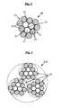
- the two layers Ci and Ce are wound in the same direction (S / S or Z / Z) and at a different pitch (preferably p 1 ⁇ p 2 ), to obtain an elementary strand of the type with cylindrical layers as represented for example in the figure 1 .
- FIG. 1 schematically, in section perpendicular to the axis of the strand (assumed to be rectilinear and at rest), an example of a preferential strand usable in the multistrand cable of the invention, having the construction 3 + 9.
- this type of construction has the consequence that the wires are arranged in two adjacent and concentric, tubular layers (Ci and Ce), giving the strand (and its two layers) an outer contour E (shown in dotted lines) which is cylindrical and non-polygonal.
- the filling rubber extends continuously around the inner layer (Ci) it covers.
- the number K of constituent elementary strands of the multistrand cable of the invention is preferably equal to 3, 4 or 5. More preferably, K is equal to 3.
- K is equal to 3 and L is equal to 1, said cable of the invention therefore having a particular construction 3x (1 + M), M being in particular equal to 5, 6 or 7.
- K is equal to 3 and L is equal to 2, said cable of the invention therefore having a particular construction 3x (2 + M), M being in particular equal to 7, 8 or 9 .
- K is equal to 3 and L is equal to 3, said cable of the invention therefore having a particular construction 3x (3 + M), M being in particular equal to 8, 9 or 10 .
- K is equal to 3 and L is equal to 4, said cable of the invention therefore having a particular construction 3 ⁇ (4 + M), M being in particular equal to 8, 9, 10 or 11.
- each of the 3 elementary strands has the same construction (3 + 9) and corresponds to the elementary strand (10) previously described in FIG. figure 1 . Its 3 constituent strands (10) could be in contact with each other; preferably they are not, which gives a greater structural elongation As to the multistrand cable of the invention.
- This multistrand cable of the invention thanks to the in situ scrubbing of its individual strands, shows a strong internal penetration by the filling rubber (14), which gives it an improved endurance vis-à-vis the fatigue corrosion ".
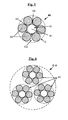
- FIG 3 schematically, in section perpendicular to the axis of the strand (assumed rectilinear and at rest), an example of another preferred strand usable in the multistrand cable of the invention, also having 3 + 9 construction.
- this type of construction has the consequence that the wires are arranged in two adjacent and concentric, tubular layers (Ci and Ce), giving the strand (and its two layers) an outer contour E (shown in dotted lines) which polygonal and non-cylindrical.
- FIG. 4 schematically, in section perpendicular to the axis of the cable (also assumed rectilinear and at rest), another example of multitoron cable (denoted C-2) according to the invention, having the construction 3 x (3 + 9).
- each of the 3 elementary strands has the same construction (3 + 9) and corresponds to the elementary strand (20) previously described in FIG. figure 3 .
- Its 3 constituent strands (20) are in this example in contact with each other; according to another preferred embodiment, they may not be in contact with one another, which gives a greater structural elongation As to the multistrand cable.
- This C-2 multistrand cable thanks to the in situ scrubbing of its individual strands, shows a strong internal penetration by the filling rubber (24), which gives it an improved endurance vis-à-vis the "fatigue”corrosion".
- FIG 5 schematically another example of a strand (40) preferable usable in the multitoron cable of the invention, having 1 + 6 construction; in this case, d 1 is slightly greater than d 2 .
- the filling rubber (44) fills, at least in part, each interstice or cavity formed by the central wire (41) and the six external wires (42) which are immediately adjacent to it; in total, 6 interstices or capillaries (45) (represented by a triangle) are thus present in this example of strand 1 + 6.
- FIG. 6 schematized as for it another preferred example of a multitoron cable according to the invention (denoted C-3), having for construction 3 x (1 + 6).
- each of the 3 elementary strands has the same construction (1 + 6) corresponding to the elementary strand (40) previously described in FIG. figure 5 .
- Its 3 constituent strands (40) could be in contact with each other; preferably they are not, which gives a greater structural elongation As to the multistrand cable of the invention.
- This multi-tonal cable C-3 thanks to the in situ scrubbing of its individual strands, has a strong internal penetration by the filling rubber (44).
- the multistrand cables of the invention are preferably of the "elastic” type (also often referred to as "HE” cables for high elongation), that is to say that they verify by definition, in the present application, at least the two characteristics: ace > 1 , 0 % ; Has > 3 , 5 % .
- At is greater than 4%.
- the present invention of course relates to multitoron cables previously described both in the green state (their filling rubber then being uncured) and in the cooked state (their filling rubber then being vulcanized).
- the multistrand cable of the invention with a filling gum in the green state until it is subsequently incorporated into the semi-finished product or finished product such as the tire for which it is intended, so as to favor the connection during the final vulcanization between the filling rubber and the surrounding rubber matrix (for example the calendering rubber).
- wire or wire is meant by definition in the present application a cable or strand formed of son constituted mainly (that is to say for more than 50% by number of these son) or integrally (for 100% son ) of a metallic material.
- the wires are preferably made of steel, more preferably of carbon steel. But it is of course possible to use other steels, for example a stainless steel, or other alloys.
- carbon steel When carbon steel is used, its carbon content (% by weight of steel) is preferably between 0.4% and 1.2%, especially between 0.5% and 1.1%; these levels represent a good compromise between the mechanical properties required for the tire and the feasibility of the wires. It should be noted that a carbon content of between 0.5% and 0.6% makes such steels ultimately less expensive because easier to draw.
- Another advantageous embodiment of the invention may also consist, depending on the applications concerned, of using steels with a low carbon content, for example between 0.2% and 0.5%, in particular because of a cost lower and easier to draw.
- the metal or steel used may itself be coated with a metal layer improving for example the properties of implementation of the wire rope and / or its constituent elements, or the properties of use of the cable and / or the tire themselves, such as adhesion properties, corrosion resistance or resistance to aging.
- the steel used is covered with a layer of brass (Zn-Cu alloy) or zinc; it is recalled that during the wire manufacturing process, the coating of brass or zinc facilitates the drawing of the wire, as well as the bonding of the wire with the rubber.
- the son could be covered with a thin metal layer other than brass or zinc, for example having the function of improving the resistance to corrosion of these son and / or their adhesion to rubber, for example a thin layer of Co, Ni, Al, an alloy of two or more compounds Cu, Zn, Al, Ni, Co, Sn.
- a thin metal layer other than brass or zinc for example having the function of improving the resistance to corrosion of these son and / or their adhesion to rubber, for example a thin layer of Co, Ni, Al, an alloy of two or more compounds Cu, Zn, Al, Ni, Co, Sn.
- the strands used in the multistrand cable of the invention are preferably made of carbon steel and have a tensile strength (Rm) preferably greater than 2500 MPa, more preferably greater than 3000 MPa.
- Rm tensile strength
- the total elongation at break (denoted At) of each constituent strand of the cable of the invention, the sum of its structural, elastic and plastic elongations, is preferably greater than 2.0%, more preferably at least 2, 5%.
- the elastomer (or indistinctly "rubber”, both of which are considered synonymous) of the filling rubber is preferably a diene elastomer, chosen more preferentially from the group consisting of polybutadienes (BR), natural rubber (NR), synthetic polyisoprenes (IR), various butadiene copolymers, different isoprene copolymers, and mixtures of these elastomers.
- BR polybutadienes
- NR natural rubber
- IR synthetic polyisoprenes
- various butadiene copolymers different isoprene copolymers, and mixtures of these elastomers.
- Such copolymers are more preferably chosen from the group consisting of butadiene-styrene copolymers (SBR), the latter being prepared by emulsion polymerization (ESBR) as in solution (SSBR), the isoprene-butadiene copolymers (BIR ), isoprene-styrene copolymers (SIR) and isoprene-butadiene-styrene copolymers (SBIR).
- SBR butadiene-styrene copolymers
- ESBR emulsion polymerization
- SBIR isoprene-butadiene copolymers
- SIR isoprene-styrene copolymers
- SBIR isoprene-butadiene-styrene copolymers
- a preferred embodiment consists in using an "isoprene" elastomer, that is to say a homopolymer or a copolymer of isoprene, in other words a diene elastomer chosen from the group consisting of natural rubber (NR). , the synthetic polyisoprenes (IR), the various isoprene copolymers and the mixtures of these elastomers.
- the isoprene elastomer is preferably natural rubber or synthetic polyisoprene of the cis-1,4 type.
- polyisoprenes having a content (mol%) of cis-1,4 bonds greater than 90%, more preferably still greater than 98%, are preferably used.
- the diene elastomer may consist, in whole or in part, of another diene elastomer such as, for example, an SBR elastomer used in or with another elastomer, for example type BR.
- the filling rubber may contain one or more elastomer (s), in particular diene (s), which may be used in combination with any type of synthetic elastomer other than diene, or even with polymers other than elastomers.
- elastomer in particular diene (s)
- diene diene
- the filling rubber is preferably of the crosslinkable type, that is to say that it comprises by definition a crosslinking system adapted to allow the crosslinking of the composition during its cooking (ie, its hardening and not its melting); thus, in such a case, this rubber composition can be described as infusible, since it can not be melted by heating at any temperature.
- the system for crosslinking the rubber sheath is a so-called vulcanization system, that is to say based on sulfur (or a sulfur-donor agent). ) and at least one vulcanization accelerator.
- vulcanization system that is to say based on sulfur (or a sulfur-donor agent).
- at least one vulcanization accelerator may be added various known vulcanization activators.
- Sulfur is used at a preferential rate of between 0.5 and 10 phr, more preferably between 1 and 8 phr
- the vulcanization accelerator for example a sulphenamide
- pce is used at a preferential rate of between 0.5 and 10.
- the invention also applies to cases where the filling gum is free of sulfur and even of any other crosslinking system, it being understood that could be sufficient, for its own crosslinking, the crosslinking or vulcanization system which is present in the rubber matrix that the cable of the invention is intended to reinforce, and capable of migrating by contact of said surrounding matrix to the filling rubber.
- the filling rubber may also comprise, in addition to said crosslinking system, all or part of the additives normally used in rubber matrices intended for the manufacture of tires, such as, for example, reinforcing fillers such as carbon black or inorganic fillers such as silica, coupling agents, anti-aging agents, antioxidants, plasticizing agents or extension oils, whether the latter are of aromatic or non-aromatic nature, especially very low or non-aromatic oils, for example of naphthenic or paraffinic type, high or preferably low viscosity, MES or TDAE oils, plasticizing resins with high Tg greater than 30 ° C, agents facilitating the implementation (processability) of compositions in the raw state , tackifying resins, anti-eversion agents, methylene acceptors and donors such as, for example, HMT (hexamethylenethane) alumina) or H3M (hexamethoxymethylmelamine), reinforcing resins (such as resorcinol or bismaleimide), known adh
- the level of reinforcing filler is preferably greater than 50 phr, for example between 60 and 140 phr. It is more preferably greater than 70 phr, for example between 70 and 120 phr.
- carbon blacks for example, all carbon blacks are suitable, in particular blacks of the HAF, ISAF, SAF type conventionally used in tires (so-called pneumatic grade blacks). Among the latter, mention will be made more particularly of carbon blacks of (ASTM) grade 300, 600 or 700 (for example N326, N330, N347, N375, N683, N772).
- Suitable reinforcing inorganic fillers are in particular silica (SiO 2 ) type inorganic fillers, in particular precipitated or fumed silica having a BET surface area of less than 450 m 2 / g, preferably from 30 to 400 m 2 / g.
- the formulation of the filling rubber can be chosen to be identical to the formulation of the rubber matrix that the cable of the invention is intended to reinforce; thus, there is no problem of compatibility between the respective materials of the filling rubber and said rubber matrix.
- the formulation of the filling gum may be chosen different from the formulation of the rubber matrix that the cable of the invention is intended to reinforce.
- the formulation of the filling gum may be adjusted by using a relatively high quantity of adhesion promoter, typically for example from 5 to 15 phr of a metal salt such as a cobalt salt, a nickel salt or a neodymium salt, and advantageously reducing the amount of said promoter (or even removing it completely) in the surrounding rubber matrix.
- the filling rubber has, in the crosslinked state, a secant modulus in extension E10 (at 10% elongation) which is between 5 and 25 MPa, more preferably between 5 and 20 MPa, in particular included in a range of 7 to 15 MPa.
- a secant modulus in extension E10 at 10% elongation
- the strands used in the multitoron cable of the invention described above could be optionally gummed in situ with a filling rubber based on elastomers other than diene, especially thermoplastic elastomers (TPE) such as for example polyurethane elastomers (TPU) not requiring a known manner of crosslinking or vulcanization but which have, at the operating temperature, properties similar to those of a vulcanized diene elastomer.
- TPE thermoplastic elastomers
- TPU polyurethane elastomers
- the present invention is implemented with a filling rubber based on diene elastomers such as previously described, thanks in particular to a specific manufacturing process which is particularly suitable for such elastomers; this manufacturing process is described in detail below.
- An essential feature of the above method is to use, both for the assembly of the inner layer Ci (when L is different from 1) than for that of the outer layer Ce, a twisting step.
- L is equal to 1, it is the single core wire which undergoes the step of sheathing the filling rubber in the green state, before assembly by twisting the M outer layer (Ce) son around core wire and sheathed.
- the L core wires are thus twisted together (direction S or Z) to form the inner layer Ci, in a manner known per se; the son are delivered by feeding means such as coils, a distribution grid, coupled or not to a connecting grain, intended to converge the core son in a common point of torsion (or point of assembly).
- the inner layer (Ci) thus formed is then sheathed with filling gum in the green state, provided by an extrusion screw at an appropriate temperature.
- the filling rubber can thus be delivered at a fixed point, unique and compact, by means of a single extrusion head, without using an individual sheathing son upstream of the assembly operations, before formation of the inner layer, as described in the prior art.
- This method has the significant advantage of not slowing down the conventional assembly process. It makes the complete initial twisting, scrubbing and final twisting operation possible in one single step, irrespective of the type of strand produced (compact strand as cylindrical strand strand), all at high speed.
- the above method can be implemented at a speed (speed of travel of the strand on the line of twisting-scrubbing) greater than 70 m / min, preferably greater than 100 m / min.
- the tension exerted on the L or yarn (s), substantially identical from one thread to another is preferably between 10 and 25% of the breaking force of the son.
- the extrusion head may comprise one or more dies, for example an upstream guide die and a downstream die calibration. It is possible to add continuous measurement and control means of the diameter of the strand connected to the extruder.
- the extrusion temperature of the filling rubber is between 60 ° C and 120 ° C, more preferably between 70 ° C and 110 ° C.
- the extrusion head thus defines a cladding zone having the shape of a cylinder of revolution whose diameter is for example between 0.4 mm and 1.2 mm, and whose length is for example between 4 and 10. mm.
- the amount of filling gum delivered by the extrusion head can be adjusted easily so that, in the final L + M strand, this amount is between 5 and 40 mg, preferably between 5 and 35 mg, especially in a range of 10 to 30 mg per g of strand.
- the inner layer Ci at any point of its periphery, is covered with a minimum thickness of filling gum which is preferably greater than 5 ⁇ m, more preferably greater than 10 ⁇ m, by example between 10 and 50 microns.
- the final assembly is performed, always by twisting (direction S or Z), M outer layer (Ce) son around the inner layer (Ci) and sheathed.
- M son come to rely on the eraser, to become embedded in the latter.
- the filling rubber, moving under the pressure exerted by these external son, then naturally tends to fill, at least in part, each of the interstices or cavities left empty by the son, between the inner layer (Ci) and the layer external (Ce).
- the L + M strand is not yet finished: its central channel in particular, delimited by the 3 or 4 core wires when L is different from 1 or 2, is not yet filled with gum. filling, in any case insufficiently to obtain an impermeability to air that is acceptable.
- the next important step is to pass the strand, thus provided with its filling rubber in the green state, through torsion balancing means to obtain a cable said to be balanced in torsion (ie that is, virtually without residual torsion);
- Torsional balancing here means, in a manner well known to those skilled in the art, the cancellation of the residual torsion torques (or of the springback of untwisting) exerted on each strand wire, in the inner layer as in the outer layer.
- Torsion balancing tools are known to those skilled in the art of twisting; they may consist for example of "trainers” and / or “twisters” and / or “twister-trainers” consisting of either pulleys for twisters or small diameter rollers for trainers, pulleys or rollers through which circulates the strand in a single plane or preferably in at least two different planes.
- the process described above exploits the rotation of the corewires, at the final stage of manufacture of the strand, in order to distribute, naturally, the filling rubber inside and around the inner layer (Ci), while perfectly controlling the amount of filling compound provided.
- Those skilled in the art will in particular be able to adjust the arrangement, the diameter of the pulleys and / or rollers of the torsion-balancing means, in order to vary the intensity of the radial pressure acting on the various wires.
- the manufacture of the elementary strand, gummed in situ by its filling rubber in the raw state, is complete.
- the elementary strands thus prepared are wound on one or more receiving coils, for storage, before the subsequent assembly operation by twisting of the K elementary strands, for the final obtaining of the multistrand cable of the invention.
- This manufacturing method naturally applies to the manufacture of elementary strands of the compact type (for recall and by definition, those whose layers Ci and Ce are wound at the same pitch and in the same direction, when L is different from 1). as strands of the type with cylindrical layers (for recall and by definition, those whose layers Ci and Ce are wound either in different steps, or in opposite directions, or again at different steps and in opposite directions, when L is different from 1).
- the method described above makes it possible to manufacture elementary strands and therefore multi-conductor cables without filling rubber at their periphery; by such an expression, it is meant that no particle of filling compound is visible, to the naked eye, at the periphery of each elementary strand or at the periphery of the multistrand cable of the invention, that is to say that is to say that the person skilled in the art makes no difference in manufacturing output, with the naked eye and at a distance of three meters or more, between a multi-conductor cable coil according to the invention and a conventional multi-conductor cable coil that is, not erased in situ.
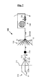
- FIG. figure 7 an example of device (100) for assembly by twisting, of the type with rotating feed and receiving, usable for the manufacture of an elementary strand of the type with cylindrical layers (not p 1 and p 2 different and / or direction of torsion different from the layers Ci and Ce), for example of construction 3 + 9 as illustrated in FIG. figure 1 .
- supply means (110) deliver L (for example three) core wires (11) through a distribution grid (111) (axisymmetrical distributor), coupled or not with a grain of assembly (112), beyond which converge L wires (11) at an assembly point or twisting point (113), for forming the inner layer (Ci).
- the inner layer Ci once formed, then passes through a cladding zone consisting for example of a single extrusion head (114) through which is intended to circulate the inner layer.
- the distance between the point of convergence (113) and the sheathing point (114) is for example between 50 cm and 1 m.
- the Ci + Ce strand thus formed is finally collected on a rotary reception (140), after passing through the torsion balancing means (130) consisting for example of a trainer or a twister-trainer.
- the manufacture of the multistrand cable of the invention one proceeds in a manner known to those skilled in the art, by twisting the elementary strands previously obtained, using twisting machines sized to assemble strands.
- the multistrand cable of the invention can be used for reinforcing articles other than tires, for example pipes, belts, conveyor belts; advantageously, it could also be used for reinforcing parts of tires other than their crown reinforcement, in particular for reinforcing the carcass reinforcement of tires for industrial vehicles.
- the cable of the invention is particularly intended for a tire crown reinforcement for heavy industrial vehicles.
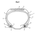
- the figure 8 very schematically represents a radial section of a metal crown reinforcement tire which may or may not be in conformity with the invention, in this general representation.
- This tire 1 has a crown 2 reinforced by a crown reinforcement or belt 6, two sidewalls 3 and two beads 4, each of these beads 4 being reinforced with a rod 5.
- the crown 2 is surmounted by a tread not shown in this schematic figure.
- a carcass reinforcement 7 is wound around the two rods 5 in each bead 4, the upturn 8 of this armature 7 being for example disposed towards the outside of the tire 1 which is shown here mounted on its rim 9.
- the carcass reinforcement 7 is in known manner constituted by at least one sheet reinforced by so-called "radial” cables, that is to say that these cables are arranged substantially parallel to each other and extend from a bead to the other so as to form an angle of between 80 ° and 90 ° with the median circumferential plane (plane perpendicular to the axis of rotation of the tire which is located halfway between the two beads 4 and passes through the middle of the crown frame 6).
- the tire according to the invention is characterized in that its belt 6 comprises at least, as reinforcement of at least one of the belt plies, a multitoron cable according to the invention.
- this belt 6 schematically in a very simple way on the figure 7
- the multistrand cables of the invention may, for example, reinforce all or part of the protective, hoop or work plies.
- this tire 1 also comprises, in a known manner, a layer of rubber or inner elastomer (commonly called "inner liner") which defines the radially inner face of the tire and which is intended to protect the carcass ply from the diffusion of air from the interior of the tire.
- the carbon steel wires are prepared in a known manner, for example starting from machine wires (diameter 5 to 6 mm) which are first cold-rolled, by rolling and / or drawing, to a neighboring intermediate diameter. of 1 mm.
- the steel used for the cable C-1 according to the invention is a high tensile type carbon steel (HT for "High Tensile ”) whose carbon content is about 0.8%.
- the intermediate diameter son undergo a degreasing treatment and / or pickling, before further processing.
- a degreasing treatment and / or pickling After deposition of a brass coating on these intermediate son, is carried on each wire a so-called “final” work hardening (ie, after the last patenting heat treatment), by cold drawing in a moist medium with a drawing lubricant which is for example in the form of an aqueous emulsion or dispersion.
- the steel wires thus drawn have the following diameter and mechanical properties: ⁇ b> Table 1 ⁇ / b> Steel ⁇ (mm) Fm (N) Rm (MPa) HT 0.23 128 3190
- wires are then assembled in the form of strands with two layers of construction 3 + 9 (referenced 10 at the Fig. 1 ) and whose mechanical properties, measured on strands extracted from a multitoron cable in accordance with the invention (3 x (3 + 9) construction with a pitch P K equal to 10 mm, as shown schematically in FIG. Fig. 2 ), are given in Table 2: ⁇ b> Table 2 ⁇ / b> Strand p 1 (mm) P 2 (mm) Fm (daN) Rm (MPa) 3 + 9 4 6 130 2710
- This strand 3 + 9 (10), as schematized at Fig. 1 , is formed of 12 wires in total, all of diameter 0.23 mm, which have been wound at different pitch and in the same direction of twist (S / S) to obtain a strand (C-1) of the type with cylindrical layers.
- the level of filling rubber, measured according to the method indicated previously in paragraph I-3, is 16 mg per g of strand.
- the filling rubber is a conventional rubber composition for tire crown reinforcement. This composition was extruded at a temperature of 90 ° C. through a calibration die of 0.530 mm.
- a flow rate of zero or less than 0.2 cm 3 / min was measured; in other words, the strands of the multistrand cables of the invention can be described as airtight along their axis; they therefore have an optimal penetration rate by rubber.
- control in situ gummed strands of the same construction as the preceding strands (10), were prepared by individually sheathing either a single wire or each of the three wires of the inner layer Ci. using extrusion dies of variable diameter (280 to 350 ⁇ m) arranged this time upstream of the assembly point (sheathing and in-line twisting) as described in the prior art (see request US 2002/160213 above); for a rigorous comparison, we adjusted on the other hand the amount of filling rubber in such a way that the rate of filling rubber in the final strands (between 4 and 30 mg / g of strand, measured according to the method of paragraph 1-3) is close to that of the strands of the cable multitorons of the invention.
- the multistrand cable of the invention is able to have improved fatigue and fatigue-corrosion endurance, while satisfying the usual wiring and scrubbing requirements in industrial conditions.
Description
La présente invention est relative aux câbles multitorons (« multistrand ropes ») utilisables notamment pour le renforcement de bandages pneumatiques pour véhicules industriels lourds tels que véhicules poids-lourd ou génie civil.The present invention relates to multistrand cables ( "multistrand ropes" ) used in particular for the reinforcement of pneumatic tires for heavy industrial vehicles such as heavy vehicles or civil engineering.
Elle est également relative aux câbles du type « gommés in situ », c'est-à-dire gommés de l'intérieur, pendant leur fabrication même, par du caoutchouc ou une composition de caoutchouc à l'état non réticulé (cru), avant incorporation de ces derniers aux articles en caoutchouc tels que pneumatiques qu'ils sont destinés à renforcer.It also relates to the cables of the type "gummed in situ", that is to say, gummed from the inside, during their manufacture, by rubber or a rubber composition in the uncrosslinked state (raw), prior to incorporation of these to rubber articles such as pneumatic that they are intended to reinforce.
Elle se rapporte également aux pneumatiques et aux armatures de renforcement du sommet encore appelées « ceintures » de ces pneumatiques, particulièrement au renforcement des ceintures de pneumatiques pour véhicules industriels.It also relates to tires and reinforcements of the crown reinforcement also called "belts" of these tires, particularly the reinforcement of tire belts for industrial vehicles.
Un pneumatique radial comporte de manière connue une bande de roulement, deux bourrelets inextensibles, deux flancs reliant les bourrelets à la bande de roulement et une ceinture disposée circonférentiellement entre l'armature de carcasse et la bande de roulement. Cette ceinture est constituée de diverses nappes (ou "couches") de caoutchouc renforcées ou non par des éléments de renforcement ("renforts") tels que des câbles ou des monofilaments, du type métalliques ou textiles.A radial tire comprises in known manner a tread, two inextensible beads, two flanks connecting the beads to the tread and a belt circumferentially disposed between the carcass reinforcement and the tread. This belt consists of various plies (or "layers") of rubber reinforced or not by reinforcing elements ("reinforcements") such as cables or monofilaments, metal or textile type.
La ceinture est généralement constituée de plusieurs nappes de ceinture superposées, dites parfois nappes "de travail" ou nappes "croisées", dont les câbles de renforcement, en général métalliques, sont disposés pratiquement parallèles les uns aux autres à l'intérieur d'une nappe, mais croisés d'une nappe à l'autre, c'est-à-dire inclinés, symétriquement ou non, par rapport au plan circonférentiel médian. Ces nappes croisées sont généralement complétées par diverses autres nappes ou couches de caoutchouc auxiliaires, de largeurs variables selon les cas, comportant ou non des renforts métalliques ; on citera en particulier les nappes dites "de protection" chargées de protéger le reste de la ceinture des agressions externes, des perforations, ou encore des nappes dites "de frettage" comportant des renforts métalliques ou non orientés sensiblement selon la direction circonférentielle (nappes dites "à zéro degré"), qu'elles soient radialement externes ou internes par rapport aux nappes croisées.The belt is generally composed of several superimposed belt plies, sometimes called "working" plies or "crossed" plies, whose reinforcing cords, generally metallic, are arranged substantially parallel to each other inside a web, but crossed from one sheet to another, that is to say, inclined, symmetrically or otherwise, with respect to the median circumferential plane. These crossed plies are generally supplemented by various other plies or layers of auxiliary rubber, of varying widths depending on the case, with or without metal reinforcements; mention will be made in particular of so-called "protection" plies responsible for protecting the rest of the belt from external aggression, perforations, or "hooping" plies comprising metal reinforcements or non-oriented substantially in the circumferential direction (so-called plies). "zero degree"), whether radially external or internal to the crossed plies.
Une telle ceinture de pneumatique doit satisfaire de manière connue à différentes exigences, souvent contradictoires, notamment :
- être la plus rigide possible à faible déformation, car elle contribue d'une manière substantielle à rigidifier le sommet du pneumatique ;
- avoir une hystérèse aussi basse que possible, pour d'une part minimiser l'échauffement en roulage de la zone interne du sommet et d'autre part réduire la résistance au roulement du pneumatique, synonyme d'économie de carburant ;
- posséder enfin une endurance élevée, vis-à-vis en particulier du phénomène de séparation, fissuration des extrémités des nappes croisées dans la zone d'épaule du pneumatique, connu sous le terme de "clivage", ce qui exige notamment des câbles métalliques qui renforcent les nappes de ceinture de présenter une résistance élevée à la fatigue en compression, le tout dans une atmosphère plus ou moins corrosive.
- be as rigid as possible with low deformation, because it contributes in a substantial way to stiffen the crown of the tire;
- to have a hysteresis as low as possible, in order firstly to minimize heating during rolling of the inner zone of the crown and secondly to reduce the rolling resistance of the tire, which is synonymous with fuel economy;
- finally possess a high endurance, vis-à-vis in particular the phenomenon of separation, cracking of the ends of the crossed plies in the shoulder area of the tire, known as "cleavage", which requires in particular metal cables which reinforce the belt plies to have a high resistance to compression fatigue, all in a more or less corrosive atmosphere.
La troisième exigence est particulièrement forte pour les pneumatiques pour véhicules industriels tels que véhicules poids-lourd ou engins de génie civil, conçus notamment pour pouvoir être rechapés une ou plusieurs fois lorsque leurs bandes de roulement atteignent un degré d'usure critique après un roulage ou usage prolongé.The third requirement is particularly strong for tires for industrial vehicles such as heavy-duty vehicles or engineering vehicles, designed in particular to be retreaded once or more when their treads reach a critical degree of wear after rolling or prolonged use.
En outre, les ceintures de pneumatiques pour véhicules industriels comportent on le sait une ou plusieurs nappes ou couches sommet dites "de protection", situées sous la bande de roulement et surmontant la ou les nappes sommet de travail, chargées de protéger le reste de la ceinture des agressions externes, déchirures ou autres perforations.In addition, tire belts for industrial vehicles are known to one or more layers or top layers called "protection", located under the tread and surmounting the working top or layers, to protect the rest of the external aggressions, tears or other perforations.
Ces nappes ou couches de protection doivent être suffisamment souples et déformables pour, d'une part, épouser au mieux la forme de l'obstacle sur lequel la ceinture appuie lors du roulage, et, d'autre part s'opposer à la pénétration de corps étrangers radialement à l'intérieur de celle-ci. La satisfaction de tels critères exige, de manière connue, l'utilisation dans ces couches de protection de renforts ou câbles présentant une haute élasticité ainsi qu'une énergie à la rupture élevée.These plies or protective layers must be sufficiently flexible and deformable to, on the one hand, conform to the shape of the obstacle on which the belt presses during rolling, and on the other hand to oppose the penetration of foreign bodies radially inside it. The satisfaction of such criteria requires, in known manner, the use in these protective layers reinforcements or cables having a high elasticity and a high energy rupture.
Pour le renforcement des nappes sommet de protection, des nappes de frettage comme des nappes sommet de travail de pneumatiques pour véhicules industriels lourds, on utilise généralement aujourd'hui des câbles à torons, notamment des câbles multitorons à une seule couche (i.e., sans âme centrale d'un ou plusieurs autres torons) de construction K x (L+M), dont les K torons élémentaires sont assemblés, enroulés simultanément en hélice en une seule couche, selon un pas d'assemblage PK ; chacun des K torons élémentaires à deux couches, de construction L+M, comporte lui-même une pluralité de fils d'acier également enroulés ensemble en hélice selon deux couches concentriques (une couche interne de L fils, une couche externe de M fils).For the reinforcement of the protective crown plies, the hooping plies as well as the working plies of tires for heavy industrial vehicles, stranded cables are usually used today, in particular multi-layer cables with a single layer (ie, without a core core of one or more other strands) of construction K x (L + M), whose K elementary strands are assembled, wound helically in a single layer, in an assembly pitch P K ; each of the K elementary strands with two layers, of construction L + M, itself comprises a plurality of steel wires also wound together in a helix according to two concentric layers (an inner layer of L son, an outer layer of M son) .
De tels câbles à torons de construction K x (L+M), notamment du type à haute élongation, sont bien connus et ont été décrits dans un grand nombre de documents brevet, en particulier pour renforcer des nappes sommet de protection de pneumatiques pour véhicules industriels tels que poids-lourd ou génie civil (voir par exemple
De manière bien connue de l'homme du métier, ces câbles à torons doivent être imprégnés autant que possible par le caoutchouc dans les ceintures de pneumatiques qu'ils renforcent, de sorte que ce caoutchouc pénètre dans la maximum d'espaces entre les fils constituant les torons. Si cette pénétration est insuffisante, il reste alors des canaux vides le long des torons, et les agents corrosifs, par exemple l'eau, susceptibles de pénétrer dans les pneumatiques par exemple à la suite de coupures ou d'autres agressions de le ceinture du pneumatique, cheminent le long de ces canaux à travers ladite ceinture. La présence de cette humidité joue un rôle important en provoquant de la corrosion et en accélérant les processus de fatigue (phénomènes dits de "fatigue-corrosion"), par rapport à une utilisation en atmosphère sèche.As is well known to those skilled in the art, these strand cables must be impregnated as much as possible by the rubber in the tire belts they reinforce, so that this rubber penetrates into the maximum of spaces between the constituent strands. the strands. If this penetration is insufficient, then empty channels remain along the strands, and corrosive agents, for example water, likely to penetrate the tires, for example as a result of cuts or other aggressions of the belt. pneumatic, run along these channels through said belt. The presence of this moisture plays an important role in causing corrosion and accelerating fatigue processes (phenomena known as "fatigue-corrosion"), compared to use in a dry atmosphere.
Tous ces phénomènes de fatigue que l'on regroupe généralement sous le terme générique de "fatigue-fretting-corrosion" sont à l'origine d'une dégénérescence progressive des propriétés mécaniques des câbles et torons et peuvent affecter, pour les conditions de roulage les plus sévères, la durée de vie de ces derniers.All these phenomena of fatigue that are generally grouped under the generic term "fatigue-fretting-corrosion" are at the origin of a progressive degeneration of the mechanical properties of the cables and strands and may affect, for the driving conditions the more severe, the lifespan of these.
Par ailleurs, il est connu qu'une bonne pénétration du câble par du caoutchouc permet, grâce à un volume d'air emprisonné dans le câble qui est moindre, de réduire les temps de cuisson des pneumatiques ("durée sous presse" réduite).Furthermore, it is known that a good penetration of the cable by rubber makes it possible, thanks to a smaller volume of air trapped in the cable, to reduce the cooking times of the tires (reduced "time in press").
Les torons élémentaires constitutifs de ces câbles multitorons, au moins pour certains, ont toutefois pour inconvénient qu'ils ne sont pas pénétrables jusqu'à coeur.The elementary strands constituting these multitoron cables, at least for some, however have the disadvantage that they are not penetrable to the core.
C'est notamment le cas des torons élémentaires de construction 3+M ou 4+M, à cause de la présence d'un canal ou capillaire au centre des trois fils d'âme, qui reste vide après imprégnation externe par du caoutchouc et donc propice, par une sorte d'effet "de mèche", à la propagation de milieux corrosifs tels que l'eau. Cet inconvénient des torons de construction 3+N est bien connu, il a été exposé par exemple dans les demandes de brevet
Pour résoudre ce problème de pénétrabilité jusqu'à coeur des câbles 3+M, la demande de brevet
Cette demande ne donne aucune information concernant la construction des torons 3+M, en particulier ni sur les pas d'assemblage ni sur les taux de gomme de remplissage à utiliser. En outre, le procédé proposé pose de nombreux problèmes.This request does not give any information concerning the construction of the 3 + M strands, in particular neither on the assembly steps nor on the levels of filling compound to be used. In addition, the proposed method poses many problems.
Tout d'abord le gainage d'un seul fil sur trois (comme illustré par exemple aux figures 11 et 12 de cette demande
En raison du très fort pouvoir collant du caoutchouc à l'état cru (c'est-à-dire non réticulé), le toron ainsi gommé devient inutilisable en raison d'un effet collant parasite sur les outils de fabrication ou entre les spires de toron lors de l'enroulage de ce dernier sur une bobine de réception, sans parler de l'impossibilité finale de calandrer correctement le câble. On rappelle ici que le calandrage consiste à transformer le câble, par incorporation entre deux couches de caoutchouc à l'état cru, en un tissu caoutchouté métallique servant de produit semi-fini pour toute fabrication ultérieure, par exemple pour la confection d'un pneumatique.Due to the very strong tackiness of the rubber in the uncured state (that is to say uncrosslinked), the strand thus gummed becomes unusable due to a parasitic sticking effect on the manufacturing tools or between the coils of strand during the winding of the latter on a receiving coil, not to mention the final impossibility of properly calender the cable. It will be recalled here that calendering consists in transforming the cable, by incorporation between two layers of rubber in the green state, into a rubberized metal fabric used as a semi-finished product for any subsequent manufacture, for example for making a tire. .
Un autre problème posé par le gainage isolé de chacun des trois fils est l'encombrement important imposé par l'emploi de trois têtes d'extrusion. En raison d'un tel encombrement, la fabrication de câbles à couches cylindriques (c'est-à-dire à pas p1 et p2 différents d'une couche à l'autre, ou à pas p1 et p2 identiques mais avec des sens de torsion différents d'une couche à l'autre) doit être nécessairement réalisée en deux opérations discontinues : (i) gainage individuel des fils puis câblage et enroulage de la couche interne dans un premier temps, (ii) câblage de la couche externe autour de la couche interne dans un deuxième temps. Toujours en raison du fort pouvoir collant du caoutchouc à l'état cru, l'enroulement et le stockage intermédiaire de la couche interne exigent l'emploi d'intercalaires ainsi que des pas de trancannage importants lors de l'enroulement sur bobine intermédiaire, pour éviter un collage parasite entre les couches bobinées ou entre les spires d'une même couche.Another problem posed by the insulated cladding of each of the three son is the large size imposed by the use of three extrusion heads. Due to such a bulk, the production of cables with cylindrical layers (that is to say not p 1 and p 2 different from one layer to another, or step p 1 and p 2 identical but with different twist directions from one layer to another) must necessarily be carried out in two discontinuous operations: (i) individual wrapping of the wires then wiring and winding of the inner layer at first, (ii) wiring of the outer layer around the inner layer in a second time. Also due to the high stickiness of the rubber in the green state, the winding and intermediate storage of the inner layer require the use of spacers and significant steps when winding on the intermediate reel, for avoid parasitic bonding between the wound layers or between the turns of the same layer.
Toutes les contraintes ci-dessus sont fortement pénalisantes du point de vue industriel et antinomiques de la recherche de cadences de fabrication élevées.All the above constraints are highly penalizing from the industrial point of view and antithetical to the search for high production rates.
Poursuivant leurs recherches, les Demanderesses ont découvert un nouveau câble multitorons de construction K x (L+M) dont les K torons élémentaires, grâce à une structure spécifique obtenue selon un procédé de fabrication particulier, permettent de pallier les inconvénients précités.Pursuing their research, the Applicants have discovered a new multi-structure cable K x (L + M) whose K elementary strands, thanks to a specific structure obtained by a particular manufacturing process, overcomes the aforementioned drawbacks.
En conséquence, un premier objet de l'invention est un câble métallique multitorons à une seule couche et de construction K x (L+M), utilisable notamment pour le renforcement de ceintures de pneumatiques pour véhicules industriels, constitué de K torons élémentaires assemblés en hélice selon un pas d'hélice PK, chaque toron élémentaire :
- o consistant en un câble à deux couches (Ci, Ce) de construction L+M, gommé in situ, comportant une couche interne (Ci) constituée de L fils de diamètre d1, L variant de 1 à 4, et une couche externe (Ce) de M fils, M étant égal ou supérieur à 5, de diamètre d2 assemblés en hélice selon un pas p2 autour de la couche interne (Ci) ;
- o et présentant les caractéristiques suivantes (d1, d2 et p2 étant exprimés en mm) :
- 0,10 < d1 < 0,50 ;
- 0,10 < d2 < 0,50 ;
- 3 < p2 <10 ;
- sa couche interne (Ci) est gainée par une composition de caoutchouc dite "gomme de remplissage" ;
- sur toute longueur de toron élémentaire égale à K fois PK, la gomme de remplissage est présente dans chacun des capillaires délimités par les L fils de la couche interne (Ci) et les M fils de la couche externe (Ce), ainsi que, lorsque L est égal à 3 ou 4, dans le canal central délimité par les L fils de la couche interne (Ci) ;
- le taux de gomme de remplissage dans ledit toron élémentaire est compris entre 5 et 40 mg par g de toron élémentaire ;
- chaque toron élémentaire est dépourvu de gomme de remplissage à sa périphérie.
- o consisting of a cable with two layers (Ci, Ce) of L + M construction, gummed in situ, comprising an inner layer (Ci) consisting of L son of diameter d 1 , L varying from 1 to 4, and an outer layer (Ce) of M son, M being equal to or greater than 5, of diameter d 2 helically assembled in a pitch p 2 around the inner layer (Ci);
- o and having the following characteristics (d 1 , d 2 and p 2 being expressed in mm):
- 0.10 <d 1 <0.50;
- 0.10 <d 2 <0.50;
- 3 <p 2 <10;
- its inner layer (Ci) is sheathed by a rubber composition called "filling rubber";
- on any elementary strand length equal to K times P K , the filling rubber is present in each of the capillaries delimited by the L wires of the inner layer (Ci) and the M wires of the outer layer (Ce), and when L is equal to 3 or 4, in the central channel delimited by the L wires of the inner layer (Ci);
- the level of filling rubber in said elementary strand is between 5 and 40 mg per g of elementary strand;
- each elementary strand is free of filling rubber at its periphery.
L'invention concerne également l'utilisation d'un tel câble multitorons pour le renforcement d'articles ou de produits semi-finis en caoutchouc, par exemple des nappes, des tuyaux, des courroies, des bandes transporteuses, des pneumatiques.The invention also relates to the use of such a multistrand cable for reinforcing articles or semi-finished products of rubber, for example webs, pipes, belts, conveyor belts, tires.
Le câble multitorons de l'invention est tout particulièrement destiné à être utilisé comme élément de renforcement d'une ceinture de pneumatique destiné à des véhicules industriels tels que véhicules "poids lourd" - i.e., métro, bus, engins de transport routier (camions, tracteurs, remorques), véhicules hors-la-route -, engins agricoles ou de génie civil, autres véhicules de transport ou de manutention.The multistrand cable of the invention is particularly intended to be used as reinforcing element of a tire belt intended for industrial vehicles such as "heavy goods vehicles" - ie, subway, bus, road transport units (trucks, tractors, trailers), off-the-road vehicles -, agricultural or engineering machinery, other transport or handling vehicles.
L'invention concerne en outre ces articles ou produits semi-finis en caoutchouc eux-mêmes lorsqu'ils sont renforcés par un câble multitorons conforme à l'invention, en particulier les pneumatiques notamment destinés aux véhicules industriels.The invention further relates to these articles or semi-finished rubber products themselves when reinforced by a multitoron cable according to the invention, in particular tires especially for industrial vehicles.
L'invention ainsi que ses avantages seront aisément compris à la lumière de la description et des exemples de réalisation qui suivent, ainsi que des
- en coupe transversale, un toron de
construction 3+9, du type à couches cylindriques, utilisable dans un câble multitorons conforme à invention (Fig. 1 ) ; - en coupe transversale, un exemple de câble multitorons conforme à l'invention, de construction 3x(3+9), incorporant le toron de la
figure 1 (Fig. 2 ) ; - en coupe transversale, un toron de
construction 3+9, du type compact, utilisable dans un câble multitorons conforme à l'invention (Fig. 3 ) ; - en coupe transversale, un exemple de câble multitorons conforme à l'invention, de construction 3x(3+9), incorporant le toron de la
figure 3 (Fig. 4 ) ; - en coupe transversale, un autre exemple de toron, de
construction 1+6, utilisable dans un câble multitorons conforme à l'invention (Fig. 5 ) ; - en coupe transversale, un autre exemple de câble multitorons conforme à l'invention, de construction 3x(1+6), incorporant le toron de la
figure 3 (Fig. 6 ) ; - un exemple d'installation de retordage et gommage in situ utilisable pour la fabrication de torons élémentaires destinés à la fabrication du câble multitorons de l'invention (
Fig. 7 ) ; - en coupe radiale, une enveloppe de pneumatique pour véhicule industriel à armature de carcasse radiale, conforme ou non à l'invention dans cette représentation générale (
Fig. 8 ).
- in transverse section, a strand of
construction 3 + 9, of the type with cylindrical layers, usable in a multitoron cable according to the invention (Fig. 1 ); - in cross-section, an example of a multitoron cable according to the invention, of construction 3x (3 + 9), incorporating the strand of the
Figure 1 (Fig. 2 ); - in cross-section, a 3 + 9 construction strand, of the compact type, that can be used in a multistrand cable according to the invention (
Fig. 3 ); - in cross-section, an example of a multitoron cable according to the invention, of construction 3x (3 + 9), incorporating the strand of the
Figure 3 (Fig. 4 ); - in cross-section, another example of strand, of
construction 1 + 6, usable in a multitoron cable according to the invention (Fig. 5 ); - in cross section, another example of a multistrand cable according to the invention, of construction 3x (1 + 6), incorporating the strand of the
figure 3 (Fig. 6 ); - an example of a twisting and in situ scrubbing installation that can be used for the production of elementary strands intended for the manufacture of the multistrand cable of the invention (
Fig. 7 ); - in radial section, a tire casing for an industrial vehicle having a radial carcass reinforcement, which may or may not conform to the invention in this general representation (
Fig. 8 ).
Pour ce qui concerne les fils et câbles métalliques, les mesures de force à la rupture notée Fm (charge maximale en N), de résistance à la rupture notée Rm (en MPa) et d'allongement à la rupture noté At (allongement total en %) sont effectuées en traction selon la norme ISO 6892 de 1984.For metal wire and cable, the breaking force measurements denoted Fm (maximum load in N), tensile strength Rm (in MPa) and elongation at break denoted At (total elongation in %) are made in tension according to ISO 6892 of 1984.
Concernant les compositions de caoutchouc diénique, les mesures de module sont effectuées en traction, sauf indication différente selon la norme ASTM D 412 de 1998 (éprouvette "C") : on mesure en seconde élongation (c'est-à-dire après un cycle d'accommodation) le module sécant "vrai" (c'est-à-dire ramené à la section réelle de l'éprouvette) à 10% d'allongement, noté E10 et exprimé en MPa (conditions normales de température et d'hygrométrie selon la norme ASTM D 1349 de 1999).With regard to the diene rubber compositions, the modulus measurements are carried out in tension, unless otherwise indicated according to the ASTM D 412 standard of 1998 (test piece "C"): one measures in second elongation (that is to say after a cycle of accommodation) the secant modulus "true" (that is to say, brought back to the real section of the specimen) at 10% elongation, denoted E10 and expressed in MPa (normal conditions of temperature and hygrometry according to ASTM D 1349 of 1999).
Ce test permet de déterminer la perméabilité longitudinale à l'air des torons élémentaires testés, par mesure du volume d'air traversant une éprouvette sous pression constante pendant un temps donné. Le principe d'un tel test, bien connu de l'homme du métier, est de démontrer l'efficacité du traitement d'un câble pour le rendre imperméable à l'air ; il a été décrit par exemple dans la norme ASTM D2692-98.This test makes it possible to determine the longitudinal air permeability of the elementary strands tested, by measuring the volume of air passing through a specimen under constant pressure for a given time. The principle of such a test, well known to those skilled in the art, is to demonstrate the effectiveness of the treatment of a cable to make it impermeable to air; it has been described for example in ASTM D2692-98.
Le test est ici réalisé sur des torons extraits des câbles multitorons bruts de fabrication, ayant subi un enrobage et une cuisson ultérieurs, ou encore extraits des pneumatiques ou des nappes de caoutchouc que renforcent ces câbles multitorons, donc déjà enrobés de caoutchouc à l'état cuit.The test is here carried out on strands extracted from the raw manufacturing multitasks cables, having undergone a subsequent coating and firing, or extracted from the tires or rubber sheets reinforced by these multistrand cables, thus already coated with rubber in the state cooked.
Dans le premier cas (câbles multitorons bruts de fabrication), les torons extraits doivent être, préalablement au test, enrobés de l'extérieur par une gomme dite d'enrobage. Pour cela, une série de 10 torons disposés parallèlement (distance inter-torons : 20 mm) est placée entre deux skims (deux rectangles de 80 x 200 mm) d'une composition de caoutchouc à l'état cru, chaque skim ayant une épaisseur de 3,5 mm ; le tout est alors bloqué dans un moule, chacun des torons étant maintenu sous une tension suffisante (par exemple 2 daN) pour garantir sa rectitude lors de la mise en place dans le moule, à l'aide de modules de serrage ; puis on procède à la vulcanisation (cuisson) pendant 40 min à une température de 140°C et sous une pression de 15 bar (piston rectangulaire de 80 x 200 mm). Après quoi, on démoule l'ensemble et on découpe 10 éprouvettes de torons ainsi enrobés, sous forme de parallélépipèdes de dimensions 7 mm x 7 mm x Lt, pour caractérisation.In the first case (raw multistrand cables), the extracted strands must be, before the test, coated from the outside by a so-called coating gum. For this, a series of 10 strands arranged in parallel (inter-strand distance: 20 mm) is placed between two skims (two rectangles of 80 x 200 mm) of a rubber composition in the raw state, each skim having a thickness 3.5 mm; the whole is then locked in a mold, each of the strands being maintained under a sufficient tension (for example 2 daN) to ensure its straightness during the establishment in the mold, using clamping modules; then the vulcanization (baking) is carried out for 40 min at a temperature of 140 ° C and a pressure of 15 bar (rectangular piston 80 x 200 mm). Thereafter, the assembly is demoulded and cut
On utilise comme gomme d'enrobage une composition de caoutchouc conventionnelle pour pneumatique, à base de caoutchouc naturel (peptisé) et de noir de carbone N330 (65 pce), comportant en outre les additifs usuels suivants: soufre (7 pce), accélérateur sulfénamide (1 pce), ZnO (8 pce), acide stéarique (0,7 pce), antioxydant (1,5 pce), naphténate de cobalt (1,5 pce) ; le module E10 de la gomme d'enrobage est de 10 MPa environ.A conventional rubber composition for tires based on natural rubber (peptized) and carbon black N330 (65 phr), comprising the following usual additives: sulfur (7 phr), sulfenamide accelerator, is used as a coating rubber. (1 phr), ZnO (8 phr), stearic acid (0.7 phr), antioxidant (1.5 phr), cobalt naphthenate (1.5 phr); the E10 module of the coating gum is approximately 10 MPa.
Le test est réalisé sur une longueur prédéterminée de toron Lt (par exemple égale à K fois PK , à 3 cm voire à 2 cm), enrobé donc par sa composition de caoutchouc (ou gomme d'enrobage) environnante, de la manière suivante : on envoie de l'air à l'entrée du toron, sous une pression de 1 bar, et on mesure le volume d'air à la sortie, à l'aide d'un débitmètre (calibré par exemple de 0 à 500 cm3/min). Pendant la mesure, l'échantillon de toron est bloqué dans un joint étanche comprimé (par exemple un joint en mousse dense ou en caoutchouc) de telle manière que seule la quantité d'air traversant le toron d'une extrémité à l'autre, selon son axe longitudinal, est prise en compte par la mesure ; l'étanchéité du joint étanche est contrôlée préalablement à l'aide d'une éprouvette de caoutchouc pleine, c'est-à-dire sans torons.The test is performed on a predetermined length of strand L t (for example equal to K times P K , 3 cm or even 2 cm), thus coated by its surrounding rubber composition (or coating gum), in the manner following: air is sent to the input of the strand under a pressure of 1 bar, and the volume of air at the outlet is measured using a flow meter (calibrated for example from 0 to 500 cm 3 / min). During the measurement, the strand sample is blocked in a compressed seal (eg a dense foam or rubber seal) such that only the amount of air passing through the strand from one end to the other, along its longitudinal axis, is taken into account by the measure; the tightness of the seal is checked beforehand with the aid of a solid rubber specimen, that is to say without strands.
Le débit d'air moyen mesuré (moyenne sur les 10 éprouvettes) est d'autant plus faible que l'imperméabilité longitudinale du toron est élevée. La mesure étant faite avec une précision de ± 0,2 cm3/min, les valeurs mesurées inférieures ou égales à 0,2 cm3/min sont considérées comme nulles ; elles correspondent à un toron qui peut être qualifié d'étanche (totalement étanche) à l'air selon son axe (i.e., dans sa direction longitudinale).The average air flow measured (average of the 10 specimens) is even lower than the longitudinal imperviousness of the strand is high. As the measurement is made with an accuracy of ± 0.2 cm 3 / min, the measured values less than or equal to 0.2 cm 3 / min are considered as zero; they correspond to a strand that can be described as airtight (totally airtight) along its axis (ie, in its longitudinal direction).
La quantité de gomme de remplissage est mesurée par différence entre le poids du toron initial (donc gommé in situ) et le poids du toron (donc celui de ses fils) dont la gomme de remplissage a été éliminée par un traitement électrolytique approprié.The amount of filling gum is measured by the difference between the weight of the initial strand (thus erased in situ) and the weight of the strand (and therefore that of its strands), the filling gum of which has been eliminated by a suitable electrolytic treatment.
Un échantillon de toron (longueur 1 m), bobiné sur lui-même pour réduire son encombrement, constitue la cathode d'un électrolyseur (reliée à la borne négative d'un générateur), tandis que l'anode (reliée à la borne positive) est constituée d'un fil de platine. L'électrolyte consiste en une solution aqueuse (eau déminéralisée) comportant 1 mole par litre de carbonate de sodium.A sample of strand (length 1 m), coiled on itself to reduce its bulk, constitutes the cathode of an electrolyzer (connected to the negative terminal of a generator), while the anode (connected to the positive terminal ) consists of a platinum wire. The electrolyte consists of an aqueous solution (demineralized water) comprising 1 mole per liter of sodium carbonate.
L'échantillon, plongé complètement dans l'électrolyte, est mis sous tension pendant 15 min sous un courant de 300 mA. Le toron est ensuite retiré du bain, rincé abondamment avec de l'eau. Ce traitement permet à la gomme de se détacher facilement du toron (si ce n'est pas le cas, on continue l'électrolyse pendant quelques minutes). On élimine soigneusement la gomme, par exemple par simple essuyage à l'aide d'un tissu absorbant, tout en détordant un à un les fils du toron. Les fils sont de nouveau rincés à l'eau puis plongés dans un bécher contenant un mélange d'eau déminéralisée (50%) et d'éthanol (50%) ; le bécher est plongé dans une cuve à ultrasons pendant 10 min. Les fils ainsi dépourvus de toute trace de gomme sont retirés du bécher, séchés sous un courant d'azote ou d'air, et enfin pesés.The sample, immersed completely in the electrolyte, is energized for 15 min under a current of 300 mA. The strand is then removed from the bath, rinsed thoroughly with water. This treatment allows the rubber to be easily detached from the strand (if it is not the case, we continue the electrolysis for a few minutes). We carefully eliminate the eraser, for example by simply wiping with an absorbent fabric, while detaching one by one the son of the strand. The threads are rinsed with water again and then immersed in a beaker containing a mixture of demineralized water (50%) and ethanol (50%); the beaker is immersed in an ultrasonic tank for 10 minutes. The yarns thus devoid of any trace of gum are removed from the beaker, dried under a stream of nitrogen or air, and finally weighed.
On en déduit par le calcul le taux de gomme de remplissage dans le toron, exprimé en mg (milligramme) de gomme de remplissage par g (gramme) de toron initial, et moyenné sur 10 mesures (c'est-à-dire sur 10 mètres de toron au total).From the calculation, the fill rate in the strand, expressed in mg (milligram) of filling gum per g (gram) of initial strand, is calculated and averaged over 10 measurements (i.e. meters of strand in total).
Dans la présente description, sauf indication expresse différente, tous les pourcentages (%) indiqués sont des % massiques.In the present description, unless expressly indicated otherwise, all the percentages (%) indicated are% by weight.
D'autre part, tout intervalle de valeurs désigné par l'expression "entre a et b" représente le domaine de valeurs allant de plus de a à moins de b (c'est-à-dire bornes a et b exclues) tandis que tout intervalle de valeurs désigné par l'expression "de a à b" signifie le domaine de valeurs allant de a jusqu'à b (c'est-à-dire incluant les bornes strictes a et b).On the other hand, any range of values designated by the expression "between a and b" represents the range of values from more than a to less than b (i.e. terminals a and b excluded) while any range of values designated by the term "from a to b" means the range from a to b (i.e., including the strict limits a and b).
Le câble métallique multitorons de l'invention est à un seule couche et a donc pour construction K x (L+M) c'est-à-dire qu'il est constitué d'un nombre K de torons élémentaires assemblés, enroulés ensemble en hélice (en une seule couche) selon un pas d'hélice PK.The multistrand metal cable of the invention is a single layer and therefore has a construction K x (L + M), that is to say that it consists of a number K of assembled elementary strands, wound together in helix (in a single layer) in a helical pitch P K.
Chacun des K torons élémentaires consiste lui-même en un câble à deux couches (Ci, Ce) de construction L+M, gommé in situ, comportant une couche interne (Ci) constituée de L fils de diamètre d1, L variant de 1 à 4, et une couche externe (Ce) de M fils, M étant égal ou supérieur à 5, de diamètre d2 enroulés ensemble en hélice selon un pas p2 autour de la couche interne (Ci).Each of the K elementary strands itself consists of a two-layer cable (Ci, Ce) of construction L + M, gummed in situ, having an inner layer (Ci) consisting of L son of diameter d 1 , L varying from 1 to 4, and an outer layer (Ce) of M son, M being equal to or greater than 5, of diameter d 2 wound helically in a pitch p 2 around the inner layer (Ci).
Chacun de ces K torons élémentaires présente en outre les caractéristiques suivantes (d1, d2 et p2 étant exprimés en mm) :
- 0,10 < d1 < 0,50 ;
- 0,10 < d2 < 0,50;
- 3 < p2 < 10 ;
- sa couche interne (Ci) est gainée par une composition de caoutchouc dite "gomme de remplissage" ;
- sur toute longueur de toron élémentaire égale à K fois PK, la gomme de remplissage est présente dans chacun des capillaires délimités par les L fils de la couche interne (Ci) et les M fils de la couche externe (Ce), ainsi que, lorsque L est égal à 3
ou 4, dans le canal central délimité par les L fils de la couche interne (Ci) ; - le taux de gomme de remplissage dans ledit toron élémentaire est compris entre 5 et 40 mg par g de toron élémentaire ;
- chaque toron élémentaire est dépourvu de gomme de remplissage à sa périphérie.
- 0.10 <d 1 <0.50;
- 0.10 <d 2 <0.50;
- 3 <p 2 <10;
- its inner layer (Ci) is sheathed by a rubber composition called "filling rubber";
- on any elementary strand length equal to K times P K , the filling rubber is present in each of the capillaries delimited by the L wires of the inner layer (Ci) and the M wires of the outer layer (Ce), and when L is equal to 3 or 4, in the central channel delimited by the L wires of the inner layer (Ci);
- the level of filling rubber in said elementary strand is between 5 and 40 mg per g of elementary strand;
- each elementary strand is free of filling rubber at its periphery.
Chaque toron élémentaire peut ainsi être qualifié de câble gommé in situ, c'est-à-dire qu'il est gommé de l'intérieur, pendant sa fabrication même (donc à l'état brut de fabrication), par la gomme de remplissage ; en d'autres termes, chacun des capillaires ou interstices (les deux termes interchangeables désignant les vides, espaces libres en l'absence de gomme de remplissage) situés entre, délimités par les L fils de la couche interne (Ci) et les M fils de la couche externe (Ce), est rempli au moins en partie, de manière continue ou non selon l'axe du toron, par la gomme de remplissage. En outre, le canal ou capillaire central formé par les 3 ou 4 fils de la couche interne Ci, lorsque L est égal à 3 ou 4, est lui aussi pénétré par de la gomme de remplissage.Each elementary strand can thus be described as a cable gummed in situ, that is to say that it is erased from the inside, during its manufacture itself (thus in the raw state of manufacture), by the filling rubber ; in other words, each of the capillaries or interstices (the two interchangeable terms designating the voids, free spaces in the absence of filling rubber) situated between, delimited by the L wires of the inner layer (Ci) and the M wires the outer layer (Ce), is filled at least in part, continuously or not along the axis of the strand, by the filling rubber. In addition, the central channel or capillary formed by the 3 or 4 wires of the inner layer Ci, when L is equal to 3 or 4, is also penetrated by the filling rubber.
Selon un mode de réalisation préférentiel, sur toute portion de toron élémentaire égale à K fois PK (plus préférentiellement égale à 3 cm, plus préférentiellement encore égale à 2 cm), le canal central (lorsque L est égal à 3 ou 4) et chaque capillaire ou interstice décrits ci-dessus comportent au moins un bouchon de gomme ; en d'autres termes et préférentiellement, il existe au moins un bouchon de gomme tous les K fois PK (plus préférentiellement tous les 3 cm, plus préférentiellement encore tous les 2 cm) de toron élémentaire, qui obstrue le canal central et chaque capillaire ou interstice du toron externe de telle manière que, au test de perméabilité à l'air (selon paragraphe I-2), chaque toron externe du câble multitorons de l'invention présente un débit d'air moyen inférieur à 2 cm3/min, plus préférentiellement inférieur à ou au plus égal à 0,2 cm3/min.According to a preferred embodiment, on any portion of elementary strand equal to K times P K (more preferably equal to 3 cm, more preferably still equal to 2 cm), the central channel (when L is equal to 3 or 4) and each capillary or interstice described above comprises at least one rubber stopper; in other words and preferably, there is at least one gum plug every K times P K (more preferably every 3 cm, more preferably every 2 cm) of elementary strand, which obstructs the central channel and each capillary or interstice of the outer strand so that, in the air permeability test (according to paragraph I-2), each outer strand of the multistrand cable of the invention has an average air flow rate of less than 2 cm 3 / min more preferably less than or equal to 0.2 cm 3 / min.
Chaque toron élémentaire a pour autre caractéristique essentielle que son taux de gomme de remplissage est compris entre 5 et 40 mg de gomme par g de toron.Each elementary strand has another essential feature that its filling gum content is between 5 and 40 mg of gum per g of strand.
En dessous du minimum indiqué, il n'est pas possible de garantir que, pour toute longueur de toron élémentaire égale à K fois PK (plus préférentiellement égale à 3 cm, encore plus préférentiellement égale à 2 cm), la gomme de remplissage soit bien présente, au moins en partie, dans chacun des interstices ou capillaire du toron élémentaire, tandis qu'au-delà du maximum indiqué, on s'expose aux différents problèmes précédemment décrits dus au débordement de la gomme de remplissage à la périphérie du toron. Pour toutes ces raisons, on préfère que le taux de gomme de remplissage soit compris entre 5 et 35 mg, plus préférentiellement encore compris dans un domaine de 10 à 30 mg par g de toron.Below the minimum indicated, it is not possible to guarantee that, for any elementary strand length equal to K times P K (more preferably equal to 3 cm, even more preferably equal to 2 cm), the filling rubber is well present, at least in part, in each of the interstices or capillary of the elementary strand, while beyond maximum indicated, it is exposed to the various problems described above due to the overflow of the filling rubber at the periphery of the strand. For all these reasons, it is preferred that the level of filling gum be between 5 and 35 mg, more preferably still within a range of 10 to 30 mg per g of strand.
Un tel taux de gomme de remplissage et son contrôle dans les limites indiquées ci-dessus n'est rendu possible que grâce à la mise en oeuvre d'un procédé de retordage-gommage spécifique, adapté à la géométrie de chaque toron élémentaire de construction L+M, procédé qui sera exposé en détail ultérieurement.Such a rate of filling rubber and its control within the limits indicated above is only possible thanks to the implementation of a specific twisting-scrubbing method, adapted to the geometry of each elementary strand of construction L + M, a process that will be discussed in detail later.
La mise en oeuvre de ce procédé spécifique, tout en permettant l'obtention d'un toron dont la quantité de gomme de remplissage est maîtrisée, garantit la présence de cloisons internes (continues ou discontinues dans l'axe du toron) ou bouchons de gomme dans chaque toron élémentaire, notamment dans son canal central lorsque L est égal à 3 ou 4, en nombre suffisant ; ainsi, chaque toron élémentaire devient étanche à la propagation, le long du toron, de tout fluide corrosif tel que l'eau ou l'oxygène de l'air, supprimant ainsi l'effet de mèche décrit en introduction du présent mémoire.The implementation of this specific process, while allowing to obtain a strand whose amount of filling rubber is controlled, ensures the presence of internal partitions (continuous or discontinuous in the axis of the strand) or rubber stoppers in each elementary strand, in particular in its central channel when L is equal to 3 or 4, in sufficient number; thus, each elementary strand becomes impervious to the propagation, along the strand, of any corrosive fluid such as water or oxygen in the air, thereby eliminating the wicking effect described in the introduction of this memo.
Selon un mode de réalisation particulièrement préférentiel de l'invention, la caractéristique suivante est vérifiée : sur toute longueur de toron élémentaire égale à K fois PK (plus préférentiellement égale à 3 cm, plus préférentiellement encore égale à 2 cm), chaque toron élémentaire est étanche ou quasiment étanche à l'air dans la direction longitudinale.According to a particularly preferred embodiment of the invention, the following characteristic is verified: on any elementary strand length equal to K times P K (more preferably equal to 3 cm, more preferably still equal to 2 cm), each elementary strand is watertight or nearly airtight in the longitudinal direction.
Au test de perméabilité à l'air décrit au paragraphe I-2, un toron élémentaire L+M dit "étanche à l'air" est caractérisé par un débit d'air moyen inférieur ou au plus égal à 0,2 cm3/min tandis qu'un toron élémentaire L+M dit "quasiment étanche à l'air" est caractérisé par un débit d'air moyen inférieur à 2 cm3/min, de préférence inférieur à 1 cm3/min.In the air permeability test described in paragraph I-2, an L + M elementary strand, referred to as "airtight", is characterized by an average air flow rate of not more than 0.2 cm 3 / min while an elementary strand L + M said "almost airtight" is characterized by an average air flow less than 2 cm 3 / min, preferably less than 1 cm 3 / min.
Pour un compromis optimisé entre résistance, faisabilité, rigidité et endurance en compression du toron, on préfère que les diamètres des fils des couches Ci et Ce, identiques ou non d'une couche à l'autre, soient compris entre 0,15 et 0,35 mm.For an optimized compromise between strength, feasibility, rigidity and compressive endurance of the strand, it is preferred that the diameters of the strands of the layers Ci and Ce, which are identical or different from one layer to another, are between 0.15 and 0. , 35 mm.
Les fils des couches Ci et Ce peuvent avoir un diamètre identique ou différent d'une couche à l'autre. On peut utiliser des fils de même diamètre d'une couche à l'autre (soit d1 = d2), ce qui simplifie notamment leur fabrication et réduit leur coût.The wires of the layers Ci and Ce may have an identical diameter or different from one layer to another. Wire of the same diameter can be used from one layer to another (ie d 1 = d 2 ), which simplifies their manufacture and reduces their cost.
Selon un mode de réalisation préférentiel, dans chaque toron élémentaire, p2 est compris dans un domaine de 12 à 25 mm.According to a preferred embodiment, in each elementary strand, p 2 is in a range of 12 to 25 mm.
Selon un autre mode de réalisation préférentiel, PK est compris entre 3 et 15 mm, plus préférentiellement compris dans un domaine de 4 à 12 mm.According to another preferred embodiment, P K is between 3 and 15 mm, more preferably in a range of 4 to 12 mm.
On rappelle ici que de manière connue le pas « p » représente la longueur, mesurée parallèlement à l'axe du toron élémentaire ou du câble multitorons, au bout de laquelle un fil ou un toron élémentaire, respectivement, ayant ce pas effectue un tour complet autour dudit axe.It will be recalled here that, in a known manner, the pitch "p" represents the length, measured parallel to the axis of the elementary strand or of the multistrand cable, at the end of which a wire or an elementary strand, respectively, having this step performs a complete revolution. around said axis.
Selon un mode de réalisation préférentiel, dans chaque toron élémentaire, L est égal à 1 c'est-à-dire qu'un fil unique constitue la couche interne (Ci) de chaque toron élémentaire.According to a preferred embodiment, in each elementary strand, L is equal to 1, that is to say that a single wire constitutes the inner layer (Ci) of each elementary strand.
Selon un autre mode de réalisation possible, dans chaque toron élémentaire, L est différent de 1 et, dans un tel cas, les L fils de diamètre d1 sont enroulés en hélice selon un pas p1 qui vérifie préférentiellement la relation : ![]()
![]()
Plus préférentiellement, dans un tel cas, dans chaque toron élémentaire, p1 est compris entre 3 et 10 mm. Selon un autre mode de réalisation plus préférentiel, dans chaque toron élémentaire, p1 est égal à p2.More preferably, in such a case, in each elementary strand, p 1 is between 3 and 10 mm. According to another more preferential embodiment, in each elementary strand, p 1 is equal to p 2 .
Selon un autre mode de réalisation préférentiel, chaque toron élémentaire vérifie la relation suivante : ![]()
plus préférentiellement encore la relation suivante : ![]()
![]()
more preferably still the following relation: ![]()
Selon un autre mode de réalisation préférentiel de l'invention, dans chaque toron élémentaire, les M fils de la couche externe (Ce) sont enroulés en hélice soit à un pas différent, soit dans un sens de torsion différent, soit à un pas et un sens de torsion tous deux différents, comparativement aux L fils de la couche interne (Ci) lorsque L est différent de 1.According to another preferred embodiment of the invention, in each elementary strand, the M son of the outer layer (Ce) are helically wound either at a different pitch, in a different direction of twist, or at a step and a twist direction both different, compared to the L wires of the inner layer (Ci) when L is different from 1.
C'est notamment le cas pour des torons à couches cylindriques tels que décrits par exemple à la
Toutefois, selon un autre mode de réalisation possible de l'invention, dans chaque toron élémentaire, les M fils de la couche externe (Ce) peuvent être enroulés en hélice au même pas et dans le même sens de torsion que les L fils de la couche interne (Ci), lorsque L est différent de 1, pour l'obtention d'une toron élémentaire du type compact (c'est-à-dire à contour polygonal) tel que représenté par exemple à la
La couche externe Ce de chacun des K torons élémentaires est préférentiellement une couche saturée c'est-à-dire que, par définition, il n'existe pas suffisamment de place dans cette couche pour y ajouter au moins un (Mmax+1)ème fil de diamètre d2, Mmax représentant le nombre maximal de fils enroulables en une couche autour de la couche interne Ci. Cette construction a pour avantage de limiter le risque de débordement de gomme de remplissage à sa périphérie et d'offrir, pour un diamètre donné de toron élémentaire, une résistance plus élevée.The outer layer Ce of each of the K elementary strands is preferably a saturated layer that is to say that, by definition, there is not enough room in this layer to add at least one (M max +1) th wire d 2 diameter, M max representing the maximum number of windable son in a layer around the inner layer Ci. This construction has the advantage of limiting the risk of overflow of filling rubber at its periphery and to offer, for a given diameter of elementary strand, a higher resistance.
Ainsi, le nombre M de fils peut varier dans une très large mesure selon le mode de réalisation particulier de l'invention, par exemple de 5 à 14 fils, étant entendu que L peut varier de 1 à 4 et que le nombre maximal Mmax de fils sera augmenté si leur diamètre d2 est réduit comparativement au diamètre d1 des L fils d'âme, afin de conserver préférentiellement la couche externe dans un état saturé.Thus, the number M of wires can vary to a very large extent according to the particular embodiment of the invention, for example from 5 to 14 wires, it being understood that L can vary from 1 to 4 and that the maximum number M max son will be increased if their diameter d 2 is reduced compared to the diameter d 1 L core son, to preferentially keep the outer layer in a saturated state.
Ainsi, selon un mode de réalisation préférentiel possible, dans chacun des K torons élémentaires, L est égal à 1 et M est plus préférentiellement égal à 5, 6 ou 7 ; en d'autres termes, chaque toron élémentaire est choisi dans le groupe des câbles de constructions 1+5, 1+6 ou 1+7. Plus préférentiellement, dans ce cas, M est égal à 6.Thus, according to a possible preferential embodiment, in each of the K elementary strands, L is equal to 1 and M is more preferably equal to 5, 6 or 7; in other words, each elementary strand is chosen from the group of
Selon un autre mode de réalisation préférentiel de l'invention, dans chacun des K torons élémentaires, L est égal à 2 et M est plus préférentiellement égal à 7, 8 ou 9 ; en d'autres termes, chaque toron élémentaire est choisi dans le groupe des câbles de constructions 2+7, 2+8 ou 2+9. Plus préférentiellement, dans ce cas, M est égal à 8.According to another preferred embodiment of the invention, in each of the K elementary strands, L is equal to 2 and M is more preferably equal to 7, 8 or 9; in other words, each elementary strand is chosen from the group of
Selon un autre mode de réalisation préférentiel de l'invention, dans chacun des K torons élémentaires, L est égal à 3 et M est plus préférentiellement égal à 8, 9 ou 10 ; en d'autres termes, chaque toron élémentaire est choisi dans le groupe des câbles de constructions 3+8, 3+9 ou 3+10. Plus préférentiellement, dans ce cas, M est égal à 9.According to another preferred embodiment of the invention, in each of the K elementary strands, L is equal to 3 and M is more preferably equal to 8, 9 or 10; in other words, each elementary strand is chosen from the group of
Selon un autre mode de réalisation préférentiel de l'invention, dans chacun des K torons élémentaires, L est égal à 4 et M est plus préférentiellement égal à 8, 9, 10 ou 11 ; en d'autres termes, chaque toron élémentaire est choisi dans le groupe des câbles de constructions 4+8, 4+9, 4+10 ou 4+11. Plus préférentiellement, dans ce cas, M est égal à 9 ou à 10.According to another preferred embodiment of the invention, in each of the K elementary strands, L is equal to 4 and M is more preferably equal to 8, 9, 10 or 11; in in other words, each elementary strand is chosen from the group of
Parmi tous les torons élémentaires préférentiels ci-dessus, les fils des deux couches (Ci, Ce) peuvent avoir le même diamètre (soit d1 = d2) ou des diamètres différents (soit d1 ≠ d2) d'une couche (Ci) à l'autre (Ce).Of all the preferential elementary strands above, the wires of the two layers (Ci, Ce) may have the same diameter (ie d 1 = d 2 ) or different diameters (or d 1 ≠ d 2 ) of a layer ( Ci) to the other (Ce).
Selon un autre mode de réalisation particulièrement préférentiel, les K torons élémentaires constitutifs du câble multitorons de l'invention sont enroulés en hélice dans le même sens de torsion que les M fils de la couche externe (Ce) de chaque toron élémentaire, ceci afin de favoriser l'élasticité du câble de l'invention.According to another particularly preferred embodiment, the constituent K constituent strands of the multi-conductor cable of the invention are helically wound in the same direction of torsion as the M wires of the outer layer (Ce) of each elementary strand, in order to promote the elasticity of the cable of the invention.
Comme déjà dit précédemment, les torons élémentaires du câble multitorons de l'invention, comme tous les câbles à couches, peuvent être de deux types, à savoir du type compact ou du type à couches cylindriques.As already mentioned above, the elementary strands of the multistrand cable of the invention, like all layered cables, can be of two types, namely of the compact type or of the type with cylindrical layers.
Préférentiellement, lorsque L est différent de 1, tous les fils des couches Ci et Ce sont enroulés dans le même sens de torsion, c'est-à-dire soit dans la direction S (disposition "S/S"), soit dans la direction Z (disposition "Z/Z"). L'enroulement dans le même sens des couches Ci et Ce permet avantageusement de minimiser les frottements entre ces deux couches et donc l'usure des fils qui les constituent. Plus préférentiellement encore, les deux couches Ci et Ce sont enroulées dans le même sens (S/S ou Z/Z) et à un pas différent (de préférence p1 < p2), pour l'obtention d'un toron élémentaire du type à couches cylindriques tel que représenté par exemple à la
La
Ce toron (10) est du type à couches cylindriques, c'est-à-dire que les fils (11, 12) de ses couches interne et externe (Ci, Ce) sont soit enroulés au même pas (p1 = p2) mais dans un sens différent (S/Z ou Z/S), soit enroulés à un pas différent (p1 # p2) quelles que soient les directions de torsion (S/S ou Z/Z ou S/Z ou Z/S). De manière connue, ce type de construction a pour conséquence que les fils sont disposés selon deux couches (Ci et Ce) adjacentes et concentriques, tubulaires, donnant au toron (et à ses deux couches) un contour externe E (représenté en pointillés) qui est cylindrique et non polygonal.This strand (10) is of the type with cylindrical layers, that is to say that the son (11, 12) of its inner and outer layers (Ci, Ce) are either wound at the same pitch (p 1 = p 2 ) but in a different direction (S / Z or Z / S), or wound in a different pitch (p 1 # p 2 ) regardless of the torsion directions (S / S or Z / Z or S / Z or Z / S). In a known manner, this type of construction has the consequence that the wires are arranged in two adjacent and concentric, tubular layers (Ci and Ce), giving the strand (and its two layers) an outer contour E (shown in dotted lines) which is cylindrical and non-polygonal.
On voit sur cette
Selon un mode de réalisation préférentiel, dans chaque toron élémentaire de construction L+M, la gomme de remplissage s'étend d'une manière continue autour de la couche interne (Ci) qu'elle recouvre.According to a preferred embodiment, in each elementary strand of L + M construction, the filling rubber extends continuously around the inner layer (Ci) it covers.
Le nombre K de torons élémentaires constitutifs du câble multitorons de l'invention est préférentiellement égal à 3, 4 ou 5. Plus préférentiellement, K est égal à 3.The number K of constituent elementary strands of the multistrand cable of the invention is preferably equal to 3, 4 or 5. More preferably, K is equal to 3.
Selon un mode de réalisation particulier et préférentiel, K est égal à 3 et L est égal à 1, ledit câble de l'invention ayant donc pour construction particulière 3x(1+M), M étant notamment égal à 5, 6 ou 7.According to a particular and preferred embodiment, K is equal to 3 and L is equal to 1, said cable of the invention therefore having a particular construction 3x (1 + M), M being in particular equal to 5, 6 or 7.
Selon un autre mode de réalisation particulier et préférentiel, K est égal à 3 et L est égal à 2, ledit câble de l'invention ayant donc pour construction particulière 3x(2+M), M étant notamment égal à 7, 8 ou 9.According to another particular and preferred embodiment, K is equal to 3 and L is equal to 2, said cable of the invention therefore having a particular construction 3x (2 + M), M being in particular equal to 7, 8 or 9 .
Selon un autre mode de réalisation particulier et préférentiel, K est égal à 3 et L est égal à 3, ledit câble de l'invention ayant donc pour construction particulière 3x(3+M), M étant notamment égal à 8, 9 ou 10.According to another particular and preferred embodiment, K is equal to 3 and L is equal to 3, said cable of the invention therefore having a particular construction 3x (3 + M), M being in particular equal to 8, 9 or 10 .
Selon un autre mode de réalisation particulier et préférentiel, K est égal à 3 et L est égal à 4, ledit câble de l'invention ayant donc pour construction particulière 3x(4+M), M étant notamment égal à 8, 9, 10 ou 11.According to another particular and preferred embodiment, K is equal to 3 and L is equal to 4, said cable of the invention therefore having a
La
Ce câble multitorons de l'invention, grâce au gommage in situ de ses torons individuels, présente on le voit une forte pénétration interne par la gomme de remplissage (14), ce qui lui confère une endurance améliorée vis-à-vis de la "fatigue corrosion".This multistrand cable of the invention, thanks to the in situ scrubbing of its individual strands, shows a strong internal penetration by the filling rubber (14), which gives it an improved endurance vis-à-vis the fatigue corrosion ".
La
Ce toron (20) est du type à couches cylindriques, c'est-à-dire que les fils (21, 22) de ses couches interne et externe (Ci, Ce) sont soit enroulés au même pas (p1 = p2) mais dans un sens différent (S/Z ou Z/S), soit enroulés à un pas différent (p1 # p2) quelles que soient les directions de torsion (S/S ou Z/Z ou S/Z ou Z/S). De manière connue, ce type de construction a pour conséquence que les fils sont disposés selon deux couches (Ci et Ce) adjacentes et concentriques, tubulaires, donnant au toron (et à ses deux couches) un contour externe E (représenté en pointillés) qui polygonal et non cylindrique.This strand (20) is of the type with cylindrical layers, that is to say that the son (21, 22) of its inner and outer layers (Ci, Ce) are either wound at the same pitch (p 1 = p 2 ) but in a different direction (S / Z or Z / S), or wound in a different pitch (p 1 # p 2 ) regardless of the torsion directions (S / S or Z / Z or S / Z or Z / S). In a known manner, this type of construction has the consequence that the wires are arranged in two adjacent and concentric, tubular layers (Ci and Ce), giving the strand (and its two layers) an outer contour E (shown in dotted lines) which polygonal and non-cylindrical.
On voit sur cette
La
La
La
Les câbles multitorons de l'invention sont préférentiellement du type "élastiques" (qualifiés aussi souvent de câbles "HE" pour haute élongation), c'est-à-dire qu'ils vérifient par définition, dans la présente demande, au moins les deux caractéristiques suivantes : 
Plus préférentiellement, At est supérieur à 4%.More preferably, At is greater than 4%.
On rappelle que de manière bien connue de l'homme du métier l'allongement total à la rupture (At) d'un câble métallique élastique est la somme de trois allongements distincts (At = As + Ae + Ap) :
- un allongement structural As, résultant de la construction, aération même du câble multitorons et/ou de ses torons élémentaires ainsi que de leur élasticité propre, le cas échéant d'une préformation imposée à un ou plusieurs de ces torons et/ou fils constitutifs ;
- un allongement élastique Ae, résultant de l'élasticité même du métal des fils métalliques, pris individuellement (loi de Hooke) ;
- un allongement plastique Ap, résultant de la plasticité (déformation irréversible au-delà de la limite d'élasticité) du métal de ces fils métalliques pris individuellement.
- a structural elongation As, resulting from the construction, even aeration of the multitoron cable and / or its elementary strands and their own elasticity, where appropriate of a preformation imposed on one or more of these strands and / or constituent son;
- an elastic elongation Ae, resulting from the elasticity of the metal of the metal wires, taken individually (Hooke's law);
- a plastic elongation Ap, resulting from the plasticity (irreversible deformation beyond the limit of elasticity) of the metal of these metal wires taken individually.
Les procédés de fabrication des câbles du type HE sont bien connus de l'homme du métier, ils ont été décrits par exemple dans la demande
La présente invention concerne bien entendu les câbles multitorons précédemment décrits tant à l'état cru (leur gomme de remplissage étant alors non vulcanisée) qu'à l'état cuit (leur gomme de remplissage étant alors vulcanisée). On préfère toutefois utiliser le câble multitorons de l'invention avec une gomme de remplissage à l'état cru jusqu'à son incorporation ultérieure dans le produit semi-fini ou produit fini tel que pneumatique auquel il est destiné, de manière à favoriser la liaison au cours de la vulcanisation finale entre la gomme de remplissage et la matrice de caoutchouc environnante (par exemple la gomme de calandrage).The present invention of course relates to multitoron cables previously described both in the green state (their filling rubber then being uncured) and in the cooked state (their filling rubber then being vulcanized). However, it is preferred to use the multistrand cable of the invention with a filling gum in the green state until it is subsequently incorporated into the semi-finished product or finished product such as the tire for which it is intended, so as to favor the connection during the final vulcanization between the filling rubber and the surrounding rubber matrix (for example the calendering rubber).
Par câble ou toron métallique, on entend par définition dans la présente demande un câble ou toron formé de fils constitués majoritairement (c'est-à-dire pour plus de 50% en nombre de ces fils) ou intégralement (pour 100% des fils) d'un matériau métallique. Les fils sont préférentiellement en acier, plus préférentiellement en acier au carbone. Mais il est bien entendu possible d'utiliser d'autres aciers, par exemple un acier inoxydable, ou d'autres alliages.By wire or wire, is meant by definition in the present application a cable or strand formed of son constituted mainly (that is to say for more than 50% by number of these son) or integrally (for 100% son ) of a metallic material. The wires are preferably made of steel, more preferably of carbon steel. But it is of course possible to use other steels, for example a stainless steel, or other alloys.
Lorsqu'un acier au carbone est utilisé, sa teneur en carbone (% en poids d'acier) est de préférence comprise entre 0,4% et 1,2%, notamment entre 0,5% et 1,1% ; ces teneurs représentent un bon compromis entre les propriétés mécaniques requises pour le pneumatique et la faisabilité des fils. Il est à noter qu'une teneur en carbone comprise entre 0,5% et 0,6% rend de tels aciers finalement moins coûteux car plus faciles à tréfiler. Un autre mode avantageux de réalisation de l'invention peut consister aussi, selon les applications visées, à utiliser des aciers à faible teneur en carbone, comprise par exemple entre 0,2% et 0,5%, en raison notamment d'un coût plus bas et d'une plus grande facilité de tréfilage.When carbon steel is used, its carbon content (% by weight of steel) is preferably between 0.4% and 1.2%, especially between 0.5% and 1.1%; these levels represent a good compromise between the mechanical properties required for the tire and the feasibility of the wires. It should be noted that a carbon content of between 0.5% and 0.6% makes such steels ultimately less expensive because easier to draw. Another advantageous embodiment of the invention may also consist, depending on the applications concerned, of using steels with a low carbon content, for example between 0.2% and 0.5%, in particular because of a cost lower and easier to draw.
Le métal ou l'acier utilisé, qu'il s'agisse en particulier d'un acier au carbone ou d'un acier inoxydable, peut être lui-même revêtu d'une couche métallique améliorant par exemple les propriétés de mise en oeuvre du câble métallique et/ou de ses éléments constitutifs, ou les propriétés d'usage du câble et/ou du pneumatique eux-mêmes, telles que les propriétés d'adhésion, de résistance à la corrosion ou encore de résistance au vieillissement. Selon un mode de réalisation préférentiel, l'acier utilisé est recouvert d'une couche de laiton (alliage Zn-Cu) ou de zinc ; on rappelle que lors du procédé de fabrication des fils, le revêtement de laiton ou de zinc facilite le tréfilage du fil, ainsi que le collage du fil avec le caoutchouc. Mais les fils pourraient être recouverts d'une fine couche métallique autre que du laiton ou du zinc, ayant par exemple pour fonction d'améliorer la résistance à la corrosion de ces fils et/ou leur adhésion au caoutchouc, par exemple une fine couche de Co, Ni, Al, d'un alliage de deux ou plus des composés Cu, Zn, Al, Ni, Co, Sn.The metal or steel used, whether it is in particular a carbon steel or a stainless steel, may itself be coated with a metal layer improving for example the properties of implementation of the wire rope and / or its constituent elements, or the properties of use of the cable and / or the tire themselves, such as adhesion properties, corrosion resistance or resistance to aging. According to a preferred embodiment, the steel used is covered with a layer of brass (Zn-Cu alloy) or zinc; it is recalled that during the wire manufacturing process, the coating of brass or zinc facilitates the drawing of the wire, as well as the bonding of the wire with the rubber. But the son could be covered with a thin metal layer other than brass or zinc, for example having the function of improving the resistance to corrosion of these son and / or their adhesion to rubber, for example a thin layer of Co, Ni, Al, an alloy of two or more compounds Cu, Zn, Al, Ni, Co, Sn.
Les torons utilisés dans le câble multitorons de l'invention sont préférentiellement en acier au carbone et possèdent une résistance en traction (Rm) de préférence supérieure à 2500 MPa, plus préférentiellement supérieure à 3000 MPa. L'allongement total à la rupture (noté At) de chaque toron constitutif du câble de l'invention, somme de ses allongements structural, élastique et plastique, est de préférence supérieur à 2,0%, plus préférentiellement au moins égal à 2,5%.The strands used in the multistrand cable of the invention are preferably made of carbon steel and have a tensile strength (Rm) preferably greater than 2500 MPa, more preferably greater than 3000 MPa. The total elongation at break (denoted At) of each constituent strand of the cable of the invention, the sum of its structural, elastic and plastic elongations, is preferably greater than 2.0%, more preferably at least 2, 5%.
L'élastomère (ou indistinctement "caoutchouc", les deux étant considérés comme synonymes) de la gomme de remplissage est préférentiellement un élastomère diénique, choisi plus préférentiellement dans le groupe constitué par les polybutadiènes (BR), le caoutchouc naturel (NR), les polyisoprènes de synthèse (IR), les différents copolymères de butadiène, les différents copolymères d'isoprène, et les mélanges de ces élastomères. De tels copolymères sont plus préférentiellement choisis dans le groupe constitué par les copolymères de butadiène-styrène (SBR), que ces derniers soient préparés par polymérisation en émulsion (ESBR) comme en solution (SSBR), les copolymères d'isoprène-butadiène (BIR), les copolymères d'isoprène-styrène (SIR) et les copolymères d'isoprène-butadiène-styrène (SBIR).The elastomer (or indistinctly "rubber", both of which are considered synonymous) of the filling rubber is preferably a diene elastomer, chosen more preferentially from the group consisting of polybutadienes (BR), natural rubber (NR), synthetic polyisoprenes (IR), various butadiene copolymers, different isoprene copolymers, and mixtures of these elastomers. Such copolymers are more preferably chosen from the group consisting of butadiene-styrene copolymers (SBR), the latter being prepared by emulsion polymerization (ESBR) as in solution (SSBR), the isoprene-butadiene copolymers (BIR ), isoprene-styrene copolymers (SIR) and isoprene-butadiene-styrene copolymers (SBIR).
Un mode de réalisation préférentiel consiste à utiliser un élastomère "isoprénique", c'est-à-dire un homopolymère ou un copolymère d'isoprène, en d'autres termes un élastomère diénique choisi dans le groupe constitué par le caoutchouc naturel (NR), les polyisoprènes de synthèse (IR), les différents copolymères d'isoprène et les mélanges de ces élastomères. L'élastomère isoprénique est de préférence du caoutchouc naturel ou un polyisoprène de synthèse du type cis-1,4. Parmi ces polyisoprènes de synthèse, sont utilisés de préférence des polyisoprènes ayant un taux (% molaire) de liaisons cis-1,4 supérieur à 90%, plus préférentiellement encore supérieur à 98%. Selon d'autres modes de réalisation préférentiels, l'élastomère diénique peut être constitué, en tout ou partie, d'un autre élastomère diénique tel que, par exemple, un élastomère SBR utilisé en coupage ou non avec un autre élastomère, par exemple du type BR.A preferred embodiment consists in using an "isoprene" elastomer, that is to say a homopolymer or a copolymer of isoprene, in other words a diene elastomer chosen from the group consisting of natural rubber (NR). , the synthetic polyisoprenes (IR), the various isoprene copolymers and the mixtures of these elastomers. The isoprene elastomer is preferably natural rubber or synthetic polyisoprene of the cis-1,4 type. Among these synthetic polyisoprenes, polyisoprenes having a content (mol%) of cis-1,4 bonds greater than 90%, more preferably still greater than 98%, are preferably used. According to other preferred embodiments, the diene elastomer may consist, in whole or in part, of another diene elastomer such as, for example, an SBR elastomer used in or with another elastomer, for example type BR.
La gomme de remplissage peut contenir un seul ou plusieurs élastomère(s) notamment diénique(s), ce dernier ou ces derniers pouvant être utilisé(s) en association avec tout type d'élastomère synthétique autre que diénique, voire avec des polymères autres que des élastomères.The filling rubber may contain one or more elastomer (s), in particular diene (s), which may be used in combination with any type of synthetic elastomer other than diene, or even with polymers other than elastomers.
La gomme de remplissage est préférentiellement du type réticulable, c'est-à-dire qu'elle comprend par définition un système de réticulation adapté pour permettre la réticulation de la composition lors de sa cuisson (i.e., son durcissement et non sa fusion) ; ainsi, dans un tel cas, cette composition de caoutchouc peut être qualifiée d'infusible, du fait qu'elle ne peut pas être fondue par chauffage à quelque température que ce soit. De préférence, dans le cas d'une composition de caoutchouc diénique, le système de réticulation de la gaine de caoutchouc est un système dit de vulcanisation, c'est-à-dire à base de soufre (ou d'un agent donneur de soufre) et d'au moins un accélérateur de vulcanisation. A ce système de vulcanisation de base peuvent s'ajouter divers activateurs de vulcanisation connus. Le soufre est utilisé à un taux préférentiel compris entre 0,5 et 10 pce, plus préférentiellement compris entre 1 et 8 pce, l'accélérateur de vulcanisation, par exemple un sulfénamide, est utilisé à un taux préférentiel compris entre 0,5 et 10 pce, plus préférentiellement compris entre 0,5 et 5,0 pce.The filling rubber is preferably of the crosslinkable type, that is to say that it comprises by definition a crosslinking system adapted to allow the crosslinking of the composition during its cooking (ie, its hardening and not its melting); thus, in such a case, this rubber composition can be described as infusible, since it can not be melted by heating at any temperature. Preferably, in the case of a diene rubber composition, the system for crosslinking the rubber sheath is a so-called vulcanization system, that is to say based on sulfur (or a sulfur-donor agent). ) and at least one vulcanization accelerator. To this basic vulcanization system may be added various known vulcanization activators. Sulfur is used at a preferential rate of between 0.5 and 10 phr, more preferably between 1 and 8 phr, the vulcanization accelerator, for example a sulphenamide, is used at a preferential rate of between 0.5 and 10. pce, more preferably between 0.5 and 5.0 phr.
Mais l'invention s'applique également aux cas où la gomme de remplissage est dépourvue de soufre et même de tout autre système de réticulation, étant entendu que pourrait suffire, pour sa propre réticulation, le système de réticulation ou vulcanisation qui est présent dans la matrice de caoutchouc que le câble de l'invention est destiné à renforcer, et susceptible de migrer par contact de ladite matrice environnante vers la gomme de remplissage.But the invention also applies to cases where the filling gum is free of sulfur and even of any other crosslinking system, it being understood that could be sufficient, for its own crosslinking, the crosslinking or vulcanization system which is present in the rubber matrix that the cable of the invention is intended to reinforce, and capable of migrating by contact of said surrounding matrix to the filling rubber.
La gomme de remplissage peut comporter également, outre ledit système de réticulation, tout ou partie des additifs habituellement utilisés dans les matrices de caoutchouc destinées à la fabrication de pneumatiques, tels que par exemple des charges renforçantes comme le noir de carbone ou des charges inorganiques comme la silice, des agents de couplage, des agents anti-vieillissement, des antioxydants, des agents plastifiants ou des huiles d'extension, que ces derniers soient de nature aromatique ou non-aromatique, notamment des huiles très faiblement ou non aromatiques, par exemple du type naphténiques ou paraffiniques, à haute ou de préférence à basse viscosité, des huiles MES ou TDAE, des résines plastifiantes à haute Tg supérieure à 30°C, des agents facilitant la mise en oeuvre (processabilité) des compositions à l'état cru, des résines tackifiantes, des agents antiréversion, des accepteurs et donneurs de méthylène tels que par exemple HMT (hexaméthylènetétramine) ou H3M (hexaméthoxyméthylmélamine), des résines renforçantes (tels que résorcinol ou bismaléimide), des systèmes promoteurs d'adhésion connus du type sels métalliques par exemple, notamment sels de cobalt, de nickel ou de lanthanide tels que décrits notamment dans la demande
Le taux de charge renforçante, par exemple du noir de carbone ou une charge inorganique renforçante telle que silice, est de préférence supérieur à 50 pce, par exemple compris entre 60 et 140 pce. Il est plus préférentiellement supérieur à 70 pce, par exemple compris entre 70 et 120 pce. Comme noirs de carbone, par exemple, conviennent tous les noirs de carbone, notamment les noirs du type HAF, ISAF, SAF conventionnellement utilisés dans les pneumatiques (noirs dits de grade pneumatique). Parmi ces derniers, on citera plus particulièrement les noirs de carbone de grade (ASTM) 300, 600 ou 700 (par exemple N326, N330, N347, N375, N683, N772). Comme charges inorganiques renforçantes conviennent notamment des charges minérales du type silice (SiO2), notamment les silice précipitées ou pyrogénées présentant une surface BET inférieure à 450 m2/g, de préférence de 30 à 400 m2/g.The level of reinforcing filler, for example carbon black or a reinforcing inorganic filler such as silica, is preferably greater than 50 phr, for example between 60 and 140 phr. It is more preferably greater than 70 phr, for example between 70 and 120 phr. As carbon blacks, for example, all carbon blacks are suitable, in particular blacks of the HAF, ISAF, SAF type conventionally used in tires (so-called pneumatic grade blacks). Among the latter, mention will be made more particularly of carbon blacks of (ASTM) grade 300, 600 or 700 (for example N326, N330, N347, N375, N683, N772). Suitable reinforcing inorganic fillers are in particular silica (SiO 2 ) type inorganic fillers, in particular precipitated or fumed silica having a BET surface area of less than 450 m 2 / g, preferably from 30 to 400 m 2 / g.
L'homme de l'art saura, à la lumière de la présente description, ajuster la formulation de la gomme de remplissage afin d'atteindre les niveaux de propriétés (notamment module d'élasticité) souhaités, et adapter la formulation à l'application spécifique envisagée.Those skilled in the art will know, in the light of the present description, adjust the formulation of the filling rubber in order to achieve the desired levels of properties (including modulus of elasticity), and adapt the formulation to the application specific consideration.
Selon un premier mode de réalisation de l'invention, la formulation de la gomme de remplissage peut être choisie identique à la formulation de la matrice de caoutchouc que le câble de l'invention est destiné à renforcer ; ainsi, il n'y a aucun problème de compatibilité entre les matériaux respectifs de la gomme de remplissage et de ladite matrice de caoutchouc.According to a first embodiment of the invention, the formulation of the filling rubber can be chosen to be identical to the formulation of the rubber matrix that the cable of the invention is intended to reinforce; thus, there is no problem of compatibility between the respective materials of the filling rubber and said rubber matrix.
Selon un second mode de réalisation de l'invention, la formulation de la gomme de remplissage peut être choisie différente de la formulation de la matrice de caoutchouc que le câble de l'invention est destiné à renforcer. On pourra notamment ajuster la formulation de la gomme de remplissage en utilisant une quantité relativement élevée de promoteur d'adhésion, typiquement par exemple de 5 à 15 pce d'un sel métallique tel qu'un sel de cobalt, un sel de nickel ou un sel de néodyme, et en réduisant avantageusement la quantité dudit promoteur (voire en le supprimant totalement) dans la matrice de caoutchouc environnante.According to a second embodiment of the invention, the formulation of the filling gum may be chosen different from the formulation of the rubber matrix that the cable of the invention is intended to reinforce. In particular, the formulation of the filling gum may be adjusted by using a relatively high quantity of adhesion promoter, typically for example from 5 to 15 phr of a metal salt such as a cobalt salt, a nickel salt or a neodymium salt, and advantageously reducing the amount of said promoter (or even removing it completely) in the surrounding rubber matrix.
De préférence, la gomme de remplissage présente, à l'état réticulé, un module sécant en extension E10 (à 10% d'allongement) qui est compris entre 5 et 25 MPa, plus préférentiellement entre 5 et 20 MPa, en particulier compris dans un domaine de 7 à 15 MPa.Preferably, the filling rubber has, in the crosslinked state, a secant modulus in extension E10 (at 10% elongation) which is between 5 and 25 MPa, more preferably between 5 and 20 MPa, in particular included in a range of 7 to 15 MPa.
L'homme du métier comprendra que les torons utilisés dans le câble multitorons de l'invention précédemment décrit pourraient être éventuellement gommés in situ avec une gomme de remplissage à base d'élastomères autres que diéniques, notamment d'élastomères thermoplastiques (TPE) tels que par exemple des élastomères polyuréthanne (TPU) ne nécessitant pas de manière connue de réticulation ou vulcanisation mais qui présentent, à la température de service, des propriétés similaires à celles d'un élastomère diénique vulcanisé.Those skilled in the art will understand that the strands used in the multitoron cable of the invention described above could be optionally gummed in situ with a filling rubber based on elastomers other than diene, especially thermoplastic elastomers (TPE) such as for example polyurethane elastomers (TPU) not requiring a known manner of crosslinking or vulcanization but which have, at the operating temperature, properties similar to those of a vulcanized diene elastomer.
Toutefois, et de manière particulièrement préférentielle, la présente invention est mise en oeuvre avec une gomme de remplissage à base d'élastomères diéniques tels que précédemment décrits, grâce notamment à un procédé de fabrication spécifique qui est particulièrement adapté à de tels élastomères ; ce procédé de fabrication est décrit en détail ci-après.However, and particularly preferably, the present invention is implemented with a filling rubber based on diene elastomers such as previously described, thanks in particular to a specific manufacturing process which is particularly suitable for such elastomers; this manufacturing process is described in detail below.
Les torons élémentaires de construction L+M précédemment décrits, gommés in situ préférentiellement par un élastomère diénique, sont susceptibles d'être fabriqués selon un procédé spécifique comportant les étapes suivantes, opérées préférentiellement en ligne et en continu :
- tout d'abord, lorsque L est différent de 1, une étape d'assemblage par retordage des L fils d'âme, pour formation de la couche interne (Ci) en un point d'assemblage ;
- puis, en aval dudit point d'assemblage des L fils d'âme (lorsque L est différent de 1), une étape de gainage de la couche interne (Ci) par la gomme de remplissage à l'état cru (c'est-à-dire non réticulée) ;
- suivie d'une étape d'assemblage par retordage des M fils de la couche externe (Ce) autour de la couche interne (Ci) ainsi gainée ;
- puis d'une étape finale d'équilibrage des torsions.
- firstly, when L is different from 1, a step of assembly by twisting L core son, for forming the inner layer (Ci) at an assembly point;
- then, downstream from said assembly point of the L core wires (when L is different from 1), a step of sheathing the inner layer (Ci) by the filling gum in the raw state (that is, that is, uncrosslinked);
- followed by a step of assembly by twisting the M son of the outer layer (Ce) around the inner layer (Ci) and sheathed;
- then a final step of balancing the twists.
On rappelle ici qu'il existe deux techniques possibles d'assemblage de fils métalliques :
- soit par câblage : dans un tel cas, les fils ne subissent pas de torsion autour de leur propre axe, en raison d'une rotation synchrone avant et après le point d'assemblage ;
- soit par retordage : dans un tel cas, les fils subissent à la fois une torsion collective et une torsion individuelle autour de leur propre axe, ce qui génère un couple de détorsion sur chacun des fils et sur le câble lui-même.
- or by wiring: in such a case, the wires are not twisted around their own axis, due to a synchronous rotation before and after the assembly point;
- or by twisting: in such a case, the son undergo both a collective twist and an individual twist around their own axis, which generates a torque of detorsion on each of the son and on the cable itself.
Une caractéristique essentielle du procédé ci-dessus est d'utiliser, tant pour l'assemblage de la couche interne Ci (lorsque L est différent de 1) que pour celui de la couche externe Ce, une étape de retordage.An essential feature of the above method is to use, both for the assembly of the inner layer Ci (when L is different from 1) than for that of the outer layer Ce, a twisting step.
Dans le cas où L est égal à 1, c'est le fil noyau unique qui subit l'étape de gainage de la gomme de remplissage à l'état cru, avant assemblage par retordage des M fils de la couche externe (Ce) autour du fil d'âme ainsi gainé.In the case where L is equal to 1, it is the single core wire which undergoes the step of sheathing the filling rubber in the green state, before assembly by twisting the M outer layer (Ce) son around core wire and sheathed.
Au cours de la première étape, les L fils d'âme sont donc retordus ensemble (direction S ou Z) pour formation de la couche interne Ci, de manière connue en soi ; les fils sont délivrés par des moyens d'alimentation tels que des bobines, une grille de répartition, couplée ou non à un grain d'assemblage, destinés à faire converger les fils d'âme en un point de torsion commun (ou point d'assemblage).During the first step, the L core wires are thus twisted together (direction S or Z) to form the inner layer Ci, in a manner known per se; the son are delivered by feeding means such as coils, a distribution grid, coupled or not to a connecting grain, intended to converge the core son in a common point of torsion (or point of assembly).
La couche interne (Ci) ainsi formée est ensuite gainée de gomme de remplissage à l'état cru, apportée par une vis d'extrusion à une température appropriée. La gomme de remplissage peut être ainsi délivrée en un point fixe, unique et de faible encombrement, au moyen d'une tête d'extrusion unique, sans faire appel à un gainage individuel des fils en amont des opérations d'assemblage, avant formation de la couche interne, comme décrit dans l'art antérieur.The inner layer (Ci) thus formed is then sheathed with filling gum in the green state, provided by an extrusion screw at an appropriate temperature. The filling rubber can thus be delivered at a fixed point, unique and compact, by means of a single extrusion head, without using an individual sheathing son upstream of the assembly operations, before formation of the inner layer, as described in the prior art.
Ce procédé a l'avantage notable de ne pas ralentir le procédé d'assemblage conventionnel. Il rend possible l'opération complète de retordage initial, gommage et retordage final en ligne et en une seule étape, quel que soit le type de toron produit (toron compact comme toron à couches cylindriques), tout ceci à haute vitesse. Le procédé ci-dessus peut être mis en oeuvre à une vitesse (vitesse de défilement du toron sur la ligne de retordage-gommage) supérieure à 70 m/min, préférentiellement supérieure à 100 m/min.This method has the significant advantage of not slowing down the conventional assembly process. It makes the complete initial twisting, scrubbing and final twisting operation possible in one single step, irrespective of the type of strand produced (compact strand as cylindrical strand strand), all at high speed. The above method can be implemented at a speed (speed of travel of the strand on the line of twisting-scrubbing) greater than 70 m / min, preferably greater than 100 m / min.
En amont de la tête d'extrusion, la tension exercée sur le ou les L fil(s), sensiblement identique d'un fil à l'autre, est préférentiellement comprise entre 10 et 25% de la force rupture des fils.Upstream of the extrusion head, the tension exerted on the L or yarn (s), substantially identical from one thread to another, is preferably between 10 and 25% of the breaking force of the son.
La tête d'extrusion peut comporter une ou plusieurs filières, par exemple une filière amont de guidage et une filière aval de calibrage. On peut ajouter des moyens de mesure et de contrôle en continu du diamètre du toron, reliés à l'extrudeuse. De préférence, la température d'extrusion de la gomme de remplissage est comprise entre 60°C et 120°C, plus préférentiellement comprise entre 70°C et 110°C. La tête d'extrusion définit ainsi une zone de gainage ayant la forme d'un cylindre de révolution dont le diamètre est compris par exemple entre 0,4 mm et 1,2 mm, et dont la longueur est par exemple comprise entre 4 et 10 mm.The extrusion head may comprise one or more dies, for example an upstream guide die and a downstream die calibration. It is possible to add continuous measurement and control means of the diameter of the strand connected to the extruder. Preferably, the extrusion temperature of the filling rubber is between 60 ° C and 120 ° C, more preferably between 70 ° C and 110 ° C. The extrusion head thus defines a cladding zone having the shape of a cylinder of revolution whose diameter is for example between 0.4 mm and 1.2 mm, and whose length is for example between 4 and 10. mm.
La quantité de gomme de remplissage délivrée par la tête d'extrusion peut être ajustée aisément de telle manière que, dans le toron L+M final, cette quantité soit comprise entre 5 et 40 mg, de préférence entre 5 et 35 mg, notamment dans un domaine de 10 à 30 mg par g de toron.The amount of filling gum delivered by the extrusion head can be adjusted easily so that, in the final L + M strand, this amount is between 5 and 40 mg, preferably between 5 and 35 mg, especially in a range of 10 to 30 mg per g of strand.
Préférentiellement, en sortie de la tête d'extrusion, la couche interne Ci, en tout point de sa périphérie, est recouverte d'une épaisseur minimale de gomme de remplissage qui est préférentiellement supérieure à 5 µm, plus préférentiellement supérieure à 10 µm, par exemple comprise entre 10 et 50 µm.Preferably, at the outlet of the extrusion head, the inner layer Ci, at any point of its periphery, is covered with a minimum thickness of filling gum which is preferably greater than 5 μm, more preferably greater than 10 μm, by example between 10 and 50 microns.
En sortie de l'étape de gainage qui précède, au cours d'une nouvelle étape, on procède à l'assemblage final, toujours par retordage (direction S ou Z), des M fils de la couche externe (Ce) autour de la couche interne (Ci) ainsi gainée. Au cours du retordage, les M fils viennent s'appuyer sur la gomme de remplissage, s'incruster dans cette dernière. La gomme de remplissage, en se déplaçant sous la pression exercée par ces fils externes, a alors naturellement tendance à remplir, au moins en partie, chacun des interstices ou cavités laissés vides par les fils, entre la couche interne (Ci) et la couche externe (Ce).At the exit of the preceding cladding step, during a new step, the final assembly is performed, always by twisting (direction S or Z), M outer layer (Ce) son around the inner layer (Ci) and sheathed. During the twisting, the M son come to rely on the eraser, to become embedded in the latter. The filling rubber, moving under the pressure exerted by these external son, then naturally tends to fill, at least in part, each of the interstices or cavities left empty by the son, between the inner layer (Ci) and the layer external (Ce).
A ce stade, le toron L+M n'est toutefois pas encore terminé : son canal central notamment, délimité par les 3 ou 4 fils d'âme lorsque L est différent de 1 ou 2, n'est pas encore rempli de gomme de remplissage, en tout cas de manière insuffisante pour l'obtention d'une imperméabilité à l'air qui soit acceptable.At this stage, however, the L + M strand is not yet finished: its central channel in particular, delimited by the 3 or 4 core wires when L is different from 1 or 2, is not yet filled with gum. filling, in any case insufficiently to obtain an impermeability to air that is acceptable.
L'étape importante qui suit consiste à faire passer le toron, ainsi pourvu de sa gomme de remplissage à l'état cru, à travers des moyens d'équilibrage de torsion pour obtention d'un câble dit équilibré en torsion (c'est-à-dire pratiquement sans torsion résiduelle) ; par "équilibrage de torsion", on entend ici de manière bien connue de l'homme du métier l'annulation des couples de torsion résiduels (ou du retour élastique de détorsion) s'exerçant sur chaque fil du toron, dans la couche interne comme dans la couche externe.The next important step is to pass the strand, thus provided with its filling rubber in the green state, through torsion balancing means to obtain a cable said to be balanced in torsion (ie that is, virtually without residual torsion); "Torsional balancing" here means, in a manner well known to those skilled in the art, the cancellation of the residual torsion torques (or of the springback of untwisting) exerted on each strand wire, in the inner layer as in the outer layer.
Les outils d'équilibrage de la torsion sont connus de l'homme du métier du retordage ; ils peuvent consister par exemple en des "dresseurs" et/ou des "retordeurs" et/ou des "retordeurs-dresseurs" constitués soit de poulies pour les retordeurs, soit de galets de petit diamètre pour les dresseurs, poulies ou galets à travers lesquels circule le toron, dans un seul plan ou de préférence dans au moins deux plans différents.Torsion balancing tools are known to those skilled in the art of twisting; they may consist for example of "trainers" and / or "twisters" and / or "twister-trainers" consisting of either pulleys for twisters or small diameter rollers for trainers, pulleys or rollers through which circulates the strand in a single plane or preferably in at least two different planes.
On suppose a posteriori que, lors du passage à travers cet outil d'équilibrage, la détorsion s'exerçant sur les L fils d'âme, entraînant une rotation inverse, au moins partielle, de ces derniers autour de leur axe, est suffisante pour forcer, pour entraîner la gomme de remplissage à l'état cru (i.e., non réticulée, non cuite) encore chaude et relativement fluide de l'extérieur vers le coeur du toron, à l'intérieur même du canal central formé par les L fils, offrant finalement aux torons constitutifs du câble multitorons de l'invention l'excellente propriété d'imperméabilité à l'air qui les caractérise. La fonction de dressage en plus, apporté par l'utilisation d'un outil dresseur, aurait pour avantage que le contact des galets du dresseur avec les fils de la couche externe va exercer une pression supplémentaire sur la gomme de remplissage favorisant encore sa pénétration dans le capillaire central formé par les L fils d'âme.It is assumed a posteriori that, during the passage through this balancing tool, the detorsion exerted on the L core wires, causing a reverse rotation, at least partial, of the latter around their axis, is sufficient to force, to drive the filling gum in the uncured state (ie, uncrosslinked, uncured) still hot and relatively fluid from the outside to the core of the strand, even within the central channel formed by the L wires finally providing the constituent strands of the multistrand cable of the invention with the excellent air impermeability characteristic which characterizes them. The additional training function, provided by the use of a trainer tool, would have the advantage that the contact of the roller of the trainer with the son of the outer layer will exert additional pressure on the filling rubber further promoting its penetration into the central capillary formed by the L son of soul.
En d'autres termes, le procédé décrit ci-dessus exploite la rotation des L fils d'âme, au stade final de fabrication du toron, pour répartir naturellement, de manière homogène, la gomme de remplissage à l'intérieur et autour de la couche interne (Ci), tout en contrôlant parfaitement la quantité de gomme de remplissage fournie. L'homme du métier saura notamment ajuster l'agencement, le diamètre des poulies et/ou des galets des moyens d'équilibrage de torsion, pour jouer sur l'intensité de la pression radiale s'exerçant sur les différents fils.In other words, the process described above exploits the rotation of the corewires, at the final stage of manufacture of the strand, in order to distribute, naturally, the filling rubber inside and around the inner layer (Ci), while perfectly controlling the amount of filling compound provided. Those skilled in the art will in particular be able to adjust the arrangement, the diameter of the pulleys and / or rollers of the torsion-balancing means, in order to vary the intensity of the radial pressure acting on the various wires.
Ainsi, de manière inattendue, il s'est avéré possible de faire pénétrer la gomme de remplissage au coeur même de chaque toron élémentaire du câble multitorons de l'invention, en déposant la gomme en aval du point d'assemblage des L fils et non en amont comme décrit dans l'art antérieur, tout en contrôlant et en optimisant la quantité de gomme de remplissage délivrée grâce à l'emploi d'une tête d'extrusion unique.Thus, unexpectedly, it has been found possible to make the filling rubber penetrate the very core of each elementary strand of the multistrand cable of the invention, by depositing the rubber downstream of the assembly point of the L wires and not upstream as described in the prior art, while controlling and optimizing the amount of filling gum delivered through the use of a single extrusion head.
Après cette étape ultime d'équilibrage de la torsion, la fabrication du toron élémentaire, gommé in situ par sa gomme de remplissage à l'état cru, est terminée. Les torons élémentaires ainsi préparés sont enroulés sur ou plusieurs bobines de réception, pour stockage, avant l'opération ultérieure d'assemblage par retordage des K torons élémentaires, pour l'obtention finale du câble multitorons de l'invention.After this final step of balancing the torsion, the manufacture of the elementary strand, gummed in situ by its filling rubber in the raw state, is complete. The elementary strands thus prepared are wound on one or more receiving coils, for storage, before the subsequent assembly operation by twisting of the K elementary strands, for the final obtaining of the multistrand cable of the invention.
Ce procédé de fabrication s'applique bien entendu à la fabrication de torons élémentaires du type compacts (pour rappel et par définition, ceux dont les couches Ci et Ce sont enroulées au même pas et dans le même sens, lorsque L est différent de 1) comme de torons du type à couches cylindriques (pour rappel et par définition, ceux dont les couches Ci et Ce sont enroulées soit à des pas différents, soit dans des sens opposés, soit encore à des pas différents et dans des sens opposés, lorsque L est différent de 1).This manufacturing method naturally applies to the manufacture of elementary strands of the compact type (for recall and by definition, those whose layers Ci and Ce are wound at the same pitch and in the same direction, when L is different from 1). as strands of the type with cylindrical layers (for recall and by definition, those whose layers Ci and Ce are wound either in different steps, or in opposite directions, or again at different steps and in opposite directions, when L is different from 1).
Le procédé précédemment décrit rend possible, la fabrication de torons élémentaires et donc de câble multitorons dépourvus de gomme de remplissage à leur périphérie ; par une telle expression, on entend qu'aucune particule de gomme de remplissage n'est visible, à l'oeil nu, à la périphérie de chaque toron élémentaire ni à la périphérie du câble multitorons de l'invention, c'est-à-dire que l'homme du métier ne fait pas de différence en sortie de fabrication, à l'oeil nu et à une distance de trois mètres ou plus, entre une bobine de câble multitorons selon l'invention et une bobine de câble multitorons conventionnel c'est-à-dire non gommé in situ.The method described above makes it possible to manufacture elementary strands and therefore multi-conductor cables without filling rubber at their periphery; by such an expression, it is meant that no particle of filling compound is visible, to the naked eye, at the periphery of each elementary strand or at the periphery of the multistrand cable of the invention, that is to say that is to say that the person skilled in the art makes no difference in manufacturing output, with the naked eye and at a distance of three meters or more, between a multi-conductor cable coil according to the invention and a conventional multi-conductor cable coil that is, not erased in situ.
Un dispositif d'assemblage et gommage utilisable pour la mise en oeuvre du procédé précédemment décrit est un dispositif comportant d'amont en aval, selon la direction d'avancement d'un toron élémentaire en cours de formation :
- des moyens d'alimentation du ou des L fil(s) d'âme ;
- des moyens d'assemblage par retordage des L fils d'âme, lorsque L est différent de 1, pour formation de la couche interne (Ci) ;
- des moyens de gainage de la couche interne (Ci) ;
- en sortie de moyens de gainage, des moyens d'assemblage par retordage des M fils externes autour de la couche interne ainsi gainée, pour formation de la couche externe (Ce) ;
- enfin, des moyens d'équilibrage de torsion.
- means for feeding the core wire (s);
- means for assembly by twisting the L core wires, when L is different from 1, for forming the inner layer (Ci);
- means for sheathing the inner layer (Ci);
- at the outlet of the cladding means, means for assembling by twisting the M outer threads around the inner layer thus sheathed, for forming the outer layer (Ce);
- finally, torsion balancing means.
On voit sur la
La couche interne Ci, une fois formée, traverse ensuite une zone de gainage consistant par exemple en une tête d'extrusion unique (114) à travers laquelle est destinée à circuler la couche interne. La distance entre le point de convergence (113) et le point de gainage (114) est par exemple comprise entre 50 cm et 1 m. Autour de la couche interne Ci ainsi gommée, progressant dans le sens de la flèche, sont ensuite assemblés par retordage les M fils (12) de la couche externe (Ce), par exemple au nombre de neuf, délivrés par des moyens d'alimentation (120). Le toron Ci+Ce ainsi formé est finalement collecté sur une réception tournante (140), après traversée des moyens d'équilibrage de torsion (130) consistant par exemple en un dresseur ou un retordeur-dresseur.The inner layer Ci, once formed, then passes through a cladding zone consisting for example of a single extrusion head (114) through which is intended to circulate the inner layer. The distance between the point of convergence (113) and the sheathing point (114) is for example between 50 cm and 1 m. Around the inner layer Ci thus gummed, progressing in the direction of the arrow, are then assembled by twisting the M son (12) of the outer layer (Ce), for example nine in number, delivered by feeding means (120). The Ci + Ce strand thus formed is finally collected on a rotary reception (140), after passing through the torsion balancing means (130) consisting for example of a trainer or a twister-trainer.
On rappelle ici que, de manière bien connue de l'homme du métier, pour la fabrication d'un toron 3+9 du type compact (pas p1 et p2 identiques et sens de torsion identiques des couches C1 et C2) tel qu'illustré par exemple à la
Pour la fabrication du câble multitorons de l'invention, on procède de manière connue de l'homme du métier, par retordage des torons élémentaires précédemment obtenus, à l'aide de machines de retordage dimensionnées pour assembler des torons.For the manufacture of the multistrand cable of the invention, one proceeds in a manner known to those skilled in the art, by twisting the elementary strands previously obtained, using twisting machines sized to assemble strands.
Selon un mode de réalisation préférentiel, le procédé de retordage utilisé comporte les étapes connues suivantes (voir par exemple demande précitée
- enrouler ensemble en hélice les K torons élémentaires en une seule couche, selon un pas transitoire de retordage donné ;
- réaliser un surtordage destiné à réduire ce pas transitoire, c'est-à-dire destiné à augmenter l'angle d'hélice de ladite couche et, par conséquent, la courbure d'hélice de cette dernière, et
- stabiliser par détorsion le câble obtenu pour l'obtention d'un couple résiduel nul.
- winding the K elementary strands together in a single layer in a helix, according to a given transient step of twisting;
- performing an oversize to reduce this transient step, that is to say intended to increase the helix angle of said layer and, therefore, the helix curvature of the latter, and
- to stabilize by untwisting the cable obtained to obtain a zero residual torque.
Le câble multitorons de l'invention peut être utilisé pour le renforcement d'articles autres que des pneumatiques, par exemple des tuyaux, des courroies, des bandes transporteuses ; avantageusement, il pourrait être utilisé aussi pour le renforcement de parties des pneumatiques autres que leur armature de sommet, notamment pour le renforcement de l'armature de carcasse de pneumatiques pour véhicules industriels.The multistrand cable of the invention can be used for reinforcing articles other than tires, for example pipes, belts, conveyor belts; advantageously, it could also be used for reinforcing parts of tires other than their crown reinforcement, in particular for reinforcing the carcass reinforcement of tires for industrial vehicles.
Toutefois, comme expliqué en introduction du présent mémoire, le câble de l'invention est particulièrement destiné à une armature de sommet de pneumatique pour véhicules industriels lourds.However, as explained in the introduction to this memo, the cable of the invention is particularly intended for a tire crown reinforcement for heavy industrial vehicles.
A titre d'exemple, la
Ce pneumatique 1 comporte un sommet 2 renforcé par une armature de sommet ou ceinture 6, deux flancs 3 et deux bourrelets 4, chacun de ces bourrelets 4 étant renforcé avec une tringle 5. Le sommet 2 est surmonté d'une bande de roulement non représentée sur cette figure schématique. Une armature de carcasse 7 est enroulée autour des deux tringles 5 dans chaque bourrelet 4, le retournement 8 de cette armature 7 étant par exemple disposé vers l'extérieur du pneumatique 1 qui est ici représenté monté sur sa jante 9. L'armature de carcasse 7 est de manière connue en soi constituée d'au moins une nappe renforcée par des câbles dits "radiaux", c'est-à-dire que ces câbles sont disposés pratiquement parallèles les uns aux autres et s'étendent d'un bourrelet à l'autre de manière à former un angle compris entre 80° et 90° avec le plan circonférentiel médian (plan perpendiculaire à l'axe de rotation du pneumatique qui est situé à mi-distance des deux bourrelets 4 et passe par le milieu de l'armature de sommet 6).This
Le pneumatique conforme à l'invention est caractérisé en ce que sa ceinture 6 comporte au moins, à titre de renforcement d'au moins une des nappes de ceinture, un câble multitorons conforme à l'invention. Dans cette ceinture 6 schématisée de manière très simple sur la
Les essais qui suivent démontrent la capacité de l'invention à fournir des câbles multitorons dont l'endurance, en particulier en ceinture de pneumatique, peut être notablement augmentée grâce à une excellente propriété d'imperméabilité à l'air des torons constitutifs de ces câbles.The following tests demonstrate the ability of the invention to provide multi-core cables whose endurance, in particular tire belt, can be significantly increased thanks to an excellent property of air impermeability of the strands constituting these cables. .
A titre de torons élémentaires, on utilise dans les essais qui suivent des torons à deux couches de constructions 3+9 tels que schématisés à la
Les fils en acier au carbone sont préparés de manière connue, en partant par exemple de fils machine (diamètre 5 à 6 mm) que l'on écrouit tout d'abord, par laminage et/ou tréfilage, jusqu'à un diamètre intermédiaire voisin de 1 mm. L'acier utilisé pour le câble C-1 conforme à l'invention est un acier au carbone du type à haute résistance (dit HT pour " High Tensile ") dont la teneur en carbone est de 0,8 % environ.The carbon steel wires are prepared in a known manner, for example starting from machine wires (
Les fils de diamètre intermédiaire subissent un traitement de dégraissage et/ou décapage, avant leur transformation ultérieure. Après dépôt d'un revêtement de laiton sur ces fils intermédiaires, on effectue sur chaque fil un écrouissage dit "final" (i.e., après le dernier traitement thermique de patentage), par tréfilage à froid en milieu humide avec un lubrifiant de tréfilage qui se présente par exemple sous forme d'une émulsion ou d'une dispersion aqueuses.The intermediate diameter son undergo a degreasing treatment and / or pickling, before further processing. After deposition of a brass coating on these intermediate son, is carried on each wire a so-called "final" work hardening (ie, after the last patenting heat treatment), by cold drawing in a moist medium with a drawing lubricant which is for example in the form of an aqueous emulsion or dispersion.
Les fils en acier ainsi tréfilés ont le diamètre et les propriétés mécaniques suivantes :
Ces fils sont ensuite assemblés sous forme de torons à deux couches de construction 3+9 (référencés 10 à la
Ce toron 3+9 (10), tel que schématisé à la
Pour la fabrication de ce toron, on a utilisé un dispositif tel que décrit précédemment et schématisé à la
Les torons (3+9) précédemment fabriqués ont été par ailleurs soumis au test de perméabilité à l'air décrit au paragraphe I-2, sur des longueurs de torons de 3 cm (soit égales à 3 fois PK), en mesurant le volume d'air (en cm3) traversant les torons en 1 minute (moyenne de 10 mesures pour chaque toron testé).Previously fabricated strands (3 + 9) were furthermore subjected to the air permeability test described in paragraph I-2, on strand lengths of 3 cm (equal to 3 times P K ), measuring the volume of air (in cm 3 ) passing through the strands in 1 minute (average of 10 measurements for each strand tested).
Pour chaque toron (10) testé et pour 100% des mesures (soit dix éprouvettes sur dix), on a mesuré un débit nul ou inférieur à 0,2 cm3/min ; en d'autres termes, les torons des câbles multitorons de l'invention peuvent être qualifiés d'étanches à l'air selon leur axe ; ils présentent donc un taux de pénétration optimal par le caoutchouc.For each strand (10) tested and for 100% of the measurements (ie ten test pieces out of ten), a flow rate of zero or less than 0.2 cm 3 / min was measured; in other words, the strands of the multistrand cables of the invention can be described as airtight along their axis; they therefore have an optimal penetration rate by rubber.
Par ailleurs, des torons gommés in situ témoins, de même construction que les torons (10) précédents, ont été préparés en gainant individuellement soit un seul fil, soit chacun des trois fils de la couche interne Ci. Ce gainage a été réalisé à l'aide de filières d'extrusion de diamètre variable (280 à 350 µm) disposées cette fois en amont du point d'assemblage (gainage et retordage en ligne) comme décrit dans l'art antérieur (voir demande
Dans le cas du gainage d'un seul fil, quel que soit le toron testé, on a observé que 100% des mesures (i.e., 10 éprouvettes sur 10) indiquaient un débit d'air supérieur à 2 cm3/min ; le débit moyen mesuré variait de 4 à 15 cm3/min selon les conditions opératoires utilisées, notamment le diamètre de filière d'extrusion testé. En d'autres termes, aucun des torons témoins ci-dessus testés ne peut être qualifié de toron étanche à l'air selon son axe longitudinal, au sens du test du paragraphe I-2.In the case of jacketing a single wire, regardless of the strand tested, it was observed that 100% of the measurements (ie, 10 test pieces out of 10) indicated an air flow rate greater than 2 cm 3 / min; the average flow rate measured varied from 4 to 15 cm 3 / min depending on the operating conditions used, in particular the diameter of the extrusion die tested. In other words, none of the above control strands tested can be qualified as airtight strand along its longitudinal axis, in the sense of the test of paragraph I-2.
Dans le cas du gainage individuel de chacun des trois fils, si le débit moyen mesuré s'est révélé dans de nombreux cas inférieur à 2 cm3/min, on a observé toutefois que les torons obtenus présentaient une quantité relativement importante de gomme de remplissage à leur périphérie, les rendant inaptes à une opération de calandrage en conditions industrielles.In the case of the individual cladding of each of the three yarns, although the measured average flow rate was in many cases less than 2 cm 3 / min, it was observed however that the strands obtained had a relatively large amount of filling rubber. at their periphery, making them unsuitable for a calendering operation in industrial conditions.
En conclusion, grâce à la construction spécifique de ses torons externes constitutifs et l'excellente imperméabilité à l'air qui les caractérise, le câble multitorons de l'invention est apte à présenter une endurance améliorée en fatigue et fatigue-corrosion, tout en satisfaisant aux exigences habituelles de câblage et gommage en conditions industrielles.In conclusion, thanks to the specific construction of its constituent outer strands and the excellent impermeability to air which characterizes them, the multistrand cable of the invention is able to have improved fatigue and fatigue-corrosion endurance, while satisfying the usual wiring and scrubbing requirements in industrial conditions.
Claims (15)
- Multistrand metal cord consisting of K elementary strands assembled in a helix, each elementary strand:o consisting of a cord having two layers (Ci, Ce) of L+M construction, rubberized in situ, comprising an inner layer (Ci) consisting of L wires of diameter d1, L varying from 1 to 4, and an outer layer (Ce) of M wires, M being equal to or greater than 5, of diameter d2, which are assembled in a helix with a pitch p2 around the inner layer (Ci); its inner layer (Ci) is sheathed with a rubber composition called a "filling rubber"; each elementary strand having the following characteristics (d1, d2 being expressed in mm):- 0.10 <d1 < 0.50;- 0.10 < d2 < 0.50;characterized in that each elementary strand has the following characteristics (p2 being expressed in mm):- 3 < p2 < 10;- said K elementary strand being assembled in a helix with a helix pitch PK, over any length of the elementary strand equal to K times PK, the filling rubber is present in each of the capillaries delimited by the L wires of the inner layer (Ci) and the M wires of the outer layer (Ce), and also, when L is equal to 3 or 4, in the central channel delimited by the L wires of the inner layer (Ci); and- the amount of filling rubber in said elementary strand is between 5 and 40 mg per g of elementary strand;- each elementary strand has no filling rubber on its periphery ;
and in that the cord is a one layer cord and of the Kx(L+M) construction. - Cord according to Claim 1, in which, in each elementary strand, the following characteristics are satisfied:- 0.15 < d1 < 0.35;- 0.15 < d2 < 0.35.
- Cord according to Claim 1 or 2, in which, in each elementary strand, p2 is in the range from 4 to 8 mm.
- Cord according to any one of Claims 1 to 3, in which PK is between 3 and 15 mm, preferably in the range from 4 to 12 mm.
- Cord according to any one of Claims 1 to 4, in which, in each elementary strand, L is equal to 1 and M is equal to 5, 6 or 7.
- Cord according to any one of Claims 1 to 4, in which, in each elementary strand, L is different from 1 and the L wires of diameter d1 are helically wound with a pitch p1 satisfying the relationship:

- Cord according to Claim 6, in which, in each elementary strand, p1 is between 3 and 10 mm.
- Cord according to Claim 6 or 7, in which, in each elementary strand, p1 is equal to P2.
- Cord according to any one of Claims 1 to 8, in which, in each outer strand, the elementary layer is a saturated layer.
- Cord according to any one of Claims 1 to 9, in which the K elementary strands are wound in a helix in the same twist direction as the M wires of the outer layer (Ce) of each elementary strand.
- Cord according to any one of Claims 1 to 10, in which, in each elementary strand, the rubber of the filling rubber is a diene rubber, preferably is chosen from the group formed by polybutadienes, natural rubber, synthetic polyisoprenes, butadiene copolymers, isoprene copolymers and the blends of these elastomers.
- Cord according to any one of Claims 1 to 11, in which, in each elementary strand, the amount of filling rubber is between 5 and 35 mg per g of elementary strand.
- Cord according to any one of Claims 1 to 12, characterized in that, in the air permeability test (paragraph I-2), each elementary strand has an average air flow rate of less than 2 cm3/min, preferably less than or at most equal to 0.2 cm3/min.
- Cord according to any one of Claims 1 to 13, in which K is equal to 3, 4 or 5, preferably equal to 3.
- Tyre comprising a cord according to any one of Claims 1 to 14, said multistrand cord being present in the belt of the tyre.
Applications Claiming Priority (2)
| Application Number | Priority Date | Filing Date | Title |
|---|---|---|---|
| FR0954595A FR2947575B1 (en) | 2009-07-03 | 2009-07-03 | CABLE MULTITORONS WHOSE ELEMENTARY TORONES ARE CABLES WITH TWO LAYERS GOMMES IN SITU. |
| PCT/EP2010/059525 WO2011000964A2 (en) | 2009-07-03 | 2010-07-05 | Multi-strand cord in which the basic strands are dual layer cords, rubberised in situ |
Publications (2)
| Publication Number | Publication Date |
|---|---|
| EP2449170A2 EP2449170A2 (en) | 2012-05-09 |
| EP2449170B1 true EP2449170B1 (en) | 2015-11-11 |
Family
ID=41668456
Family Applications (1)
| Application Number | Title | Priority Date | Filing Date |
|---|---|---|---|
| EP10728671.8A Active EP2449170B1 (en) | 2009-07-03 | 2010-07-05 | Multi strand cable, wherein each strand is rubberized in-situ |
Country Status (9)
| Country | Link |
|---|---|
| US (1) | US8857146B2 (en) |
| EP (1) | EP2449170B1 (en) |
| JP (1) | JP5734966B2 (en) |
| KR (1) | KR101670113B1 (en) |
| CN (1) | CN102472001B (en) |
| BR (1) | BR112012000119A2 (en) |
| EA (1) | EA201270126A1 (en) |
| FR (1) | FR2947575B1 (en) |
| WO (1) | WO2011000964A2 (en) |
Families Citing this family (27)
| Publication number | Priority date | Publication date | Assignee | Title |
|---|---|---|---|---|
| FR2947575B1 (en) * | 2009-07-03 | 2011-08-19 | Michelin Soc Tech | CABLE MULTITORONS WHOSE ELEMENTARY TORONES ARE CABLES WITH TWO LAYERS GOMMES IN SITU. |
| FR2947574B1 (en) * | 2009-07-03 | 2012-11-09 | Michelin Soc Tech | CABLE MULTITORONS WHOSE ELEMENTARY TORONES ARE CABLES WITH TWO LAYERS GOMMES IN SITU. |
| FR2959517B1 (en) | 2010-04-28 | 2012-09-21 | Michelin Soc Tech | ELASTIC MULTITOROUS METAL CABLE WITH HIGH PERMEABILITY. |
| FR2962454B1 (en) * | 2010-05-20 | 2012-09-21 | Michelin Soc Tech | PROCESS FOR MANUFACTURING A THREE-LAYER METAL CABLE OF THE TYPE IN SITU GUM |
| FR2962456B1 (en) * | 2010-05-20 | 2012-09-21 | Michelin Soc Tech | PROCESS FOR MANUFACTURING A MULTILAYER METALLIC CABLE IN SITU GUM BY AN UNSATURATED THERMOPLASTIC ELASTOMER |
| US9506188B2 (en) * | 2013-03-14 | 2016-11-29 | Wireco Worldgroup, Inc. | Torque balanced hybrid rope |
| ES2861527T3 (en) * | 2013-08-01 | 2021-10-06 | Bekaert Sa Nv | High elongation and pneumatic steel cord comprising said cord |
| FR3022264A1 (en) | 2014-06-12 | 2015-12-18 | Michelin & Cie | SEMI-FINISHED PRODUCT COMPRISING A CABLE IN SITU GUM NOYE IN A CALENDER RUBBER COMPOSITION |
| FR3022261B1 (en) | 2014-06-12 | 2016-06-03 | Michelin & Cie | IN SITU GUM CABLE COMPRISING A SCRUB COMPOSITION COMPRISING A CORROSION INHIBITOR |
| FR3022265B1 (en) * | 2014-06-12 | 2017-12-08 | Michelin & Cie | SEMI-FINISHED PRODUCT COMPRISING A CABLE IN SITU GUM NOYE IN A CALENDER RUBBER COMPOSITION |
| FR3022262B1 (en) | 2014-06-12 | 2016-06-03 | Michelin & Cie | IN SITU GUM CABLE COMPRISING A SCRUB COMPOSITION COMPRISING A CORROSION INHIBITOR |
| FR3032978B1 (en) | 2015-02-19 | 2017-10-27 | Michelin & Cie | MULTITORON 1XN STRUCTURE CABLE FOR PNEUMATIC PROTECTION FRAME |
| FR3044967B1 (en) * | 2015-12-15 | 2017-12-22 | Michelin & Cie | PNEUMATIC TOP FOR A HEAVY VEHICLE OF GENIE CIVIL TYPE |
| FR3051398A1 (en) * | 2016-05-20 | 2017-11-24 | Michelin & Cie | PNEUMATIC HAVING PROTECTIVE LAYER WITH IMPROVED ENDURANCE PROPERTIES |
| JP2019525859A (en) * | 2016-07-01 | 2019-09-12 | コルドサ・テクニク・テクスティル・アノニム・シルケティKordsa Teknik Tekstil Anonim Sirketi | New bi-elastic polyester tire cord as cap ply |
| FR3065910A1 (en) * | 2017-05-05 | 2018-11-09 | Compagnie Generale Des Etablissements Michelin | PNEUMATIC WORKING LAYER COMPRISING MONOFILAMENTS |
| BR112020004931A2 (en) * | 2017-09-22 | 2020-09-15 | Compagnie Generale Des Etablissements Michelin | heavy duty tire top strap for construction |
| CN107953728B (en) * | 2017-11-27 | 2020-02-11 | 江苏兴达钢帘线股份有限公司 | Cable type tire bead and tire |
| CN111902577B (en) * | 2017-12-19 | 2022-02-01 | 米其林集团总公司 | Double-layer multi-strand cord with very low, low and medium modulus |
| AU2019291193A1 (en) * | 2018-06-20 | 2021-01-21 | Compagnie Generale Des Etablissements Michelin | Double-layer multi-strand cable with improved penetrability |
| AU2019291195A1 (en) * | 2018-06-20 | 2021-01-21 | Compagnie Generale Des Etablissements Michelin | Double-layer multi-strand cord with improved penetrability |
| EP3875678A4 (en) | 2018-10-30 | 2022-08-31 | Bridgestone Corporation | Elastomer reinforcement cord |
| CN109295583A (en) * | 2018-12-03 | 2019-02-01 | 江苏兴达钢帘线股份有限公司 | A kind of high elongation rate all-steel cord of engineering tire belt |
| FR3089874A3 (en) * | 2018-12-17 | 2020-06-19 | Michelin & Cie | CARCASS FRAME OF A TIRE FOR HEAVY VEHICLE OF CIVIL ENGINEERING TYPE |
| CN113165439B (en) * | 2018-12-20 | 2023-06-27 | 倍耐力轮胎股份公司 | Tyre for vehicle wheels |
| FR3092343A1 (en) * | 2019-02-05 | 2020-08-07 | Compagnie Generale Des Etablissements Michelin | High energy breaking multi-strand 1xN cable |
| FR3103500A1 (en) * | 2019-11-22 | 2021-05-28 | Compagnie Generale Des Etablissements Michelin | Two-layer multi-strand cable with improved surface fracture energy |
Citations (1)
| Publication number | Priority date | Publication date | Assignee | Title |
|---|---|---|---|---|
| US5139874A (en) * | 1991-09-05 | 1992-08-18 | The Goodyear Tire & Rubber Company | Cable for reinforcing rubber articles |
Family Cites Families (48)
| Publication number | Priority date | Publication date | Assignee | Title |
|---|---|---|---|---|
| DE19535597A1 (en) * | 1995-09-25 | 1997-03-27 | Drahtcord Saar Gmbh & Co Kg | Wire rope for reinforcement of rubber articles |
| CA2297657A1 (en) | 1997-07-22 | 1999-02-04 | Thomas Boussie | Compositions and metal complexes having ancillary ligands |
| WO1999006628A1 (en) | 1997-07-29 | 1999-02-11 | N.V. Bekaert S.A. | Steel cord for protection plies of pneumatic tyres |
| GB2332454B (en) * | 1997-12-19 | 2000-02-16 | Bridon Plc | Rope for conveying systems |
| JPH11200264A (en) * | 1998-01-20 | 1999-07-27 | Bridgestone Metalpha Kk | Steel cord for reinforcing rubber article and pneumatic tire |
| JP4582672B2 (en) * | 1998-10-20 | 2010-11-17 | 株式会社ブリヂストン | Pneumatic tire |
| FR2795751A1 (en) | 1999-06-29 | 2001-01-05 | Michelin Soc Tech | MULTILAYER STEEL CABLE FOR PNEUMATIC CARCASS |
| CN1238581C (en) | 1999-12-30 | 2006-01-25 | 米其林技术公司 | Multilay steel cable for tire carcass |
| ES2239669T3 (en) * | 2000-05-08 | 2005-10-01 | N.V. Bekaert S.A. | GALVANIZED STEEL CORD WITH IMPROVED FATIGUE RESISTANCE. |
| CN2432237Y (en) * | 2000-08-04 | 2001-05-30 | 江苏兴达钢帘线股份有限公司 | Steel cable |
| US20020053386A1 (en) * | 2000-09-11 | 2002-05-09 | The Yokohama Rubber Co., Ltd. | Steel cord for tire and radial tire |
| US7152391B2 (en) * | 2000-12-01 | 2006-12-26 | Nv Bekaert Sa | Steel cord for reinforcing off-the-road tires and conveyor belts |
| JP4355111B2 (en) * | 2001-03-30 | 2009-10-28 | 横浜ゴム株式会社 | Manufacturing method of elastomer composite steel cord |
| DE10213289A1 (en) * | 2001-03-30 | 2002-11-14 | Yokohama Rubber Co Ltd | Elastomer and steel cord composite and process for making the same |
| FR2841573A1 (en) | 2002-06-26 | 2004-01-02 | Michelin Soc Tech | LAYERED HYBRID CABLES FOR REINFORCING TIRES |
| US7594380B2 (en) | 2002-06-26 | 2009-09-29 | Michelin Recherche Et Technique S.A. | Hybrid cables with layers which can be used to reinforce tyres |
| BR0306571B1 (en) | 2002-10-11 | 2012-12-25 | cord, composite and pneumatic fabric for industrial vehicles. | |
| FR2864556B1 (en) | 2003-12-24 | 2006-02-24 | Michelin Soc Tech | LAYERED CABLE FOR PNEUMATIC CARCASS REINFORCEMENT |
| CN100589998C (en) * | 2003-12-30 | 2010-02-17 | 倍耐力轮胎公司 | Tire for vehicles |
| FR2869618B1 (en) | 2004-04-30 | 2008-10-10 | Michelin Soc Tech | IMPROVED ADHESIVE RUBBER COMPOSITION WITH A METAL REINFORCEMENT. |
| FR2870264B1 (en) * | 2004-05-12 | 2006-07-14 | Michelin Soc Tech | METAL CABLE FOR TIRES |
| FR2873721A1 (en) * | 2004-08-02 | 2006-02-03 | Michelin Soc Tech | LAYERED CABLE FOR PNEUMATIC TOP REINFORCEMENT |
| CN2736403Y (en) * | 2004-08-09 | 2005-10-26 | 刘锦兰 | Twenty-one-strand steel cord |
| JP2006218934A (en) * | 2005-02-09 | 2006-08-24 | Yokohama Rubber Co Ltd:The | Pneumatic radial tire and steel cord for carcass |
| JP5009510B2 (en) * | 2005-05-25 | 2012-08-22 | 住友ゴム工業株式会社 | Rubber composition for coating carcass cord and carcass cord coated thereby |
| US7458200B2 (en) * | 2005-12-08 | 2008-12-02 | The Goodyear Tire & Rubber Co. | High elongation cable |
| FR2897076B1 (en) * | 2006-02-09 | 2008-04-18 | Michelin Soc Tech | ELASTIC COMPOSITE CABLE FOR TIRES. |
| JP4963389B2 (en) * | 2006-09-14 | 2012-06-27 | 株式会社ブリヂストン | Steel cords, rubber-steel cord composites and tires |
| JP2009024268A (en) * | 2007-07-17 | 2009-02-05 | Bridgestone Corp | Cord for reinforcing rubber article and pneumatic tire |
| EP2184401A4 (en) * | 2007-07-17 | 2013-09-18 | Bridgestone Corp | Cord, process for producing the same, and composite of cord with rubber |
| CN201037216Y (en) * | 2007-09-06 | 2008-03-19 | 江苏兴达钢帘线股份有限公司 | High tensibility steel cord |
| DE602008006601D1 (en) * | 2007-12-21 | 2011-06-09 | Bekaert Sa Nv | STEEL ROPE WITH HEAT-CURABLE HEAT-CURING MATERIAL OF ONE COMPONENT |
| FR2925923B1 (en) * | 2007-12-28 | 2009-12-18 | Michelin Soc Tech | METHOD AND DEVICE FOR MANUFACTURING A TWO-LAYER CABLE OF THE TYPE IN SITU GUM |
| FR2925922B1 (en) * | 2007-12-28 | 2009-12-18 | Soc Tech Michelin | LAYERED CABLE FOR PNEUMATIC BELT |
| FR2934614B1 (en) * | 2008-08-01 | 2010-09-10 | Michelin Soc Tech | IN SITU GAS BED CABLE FOR PNEUMATIC CARCASE REINFORCEMENT. |
| JP5847990B2 (en) * | 2008-11-14 | 2016-01-27 | 株式会社ブリヂストン | Steel cords for reinforcing rubber articles and pneumatic tires |
| FR2940183B1 (en) * | 2008-12-22 | 2011-03-04 | Michelin Soc Tech | PNEUMATIC COMPRISING CARCASS FRAME CABLES HAVING LOW PERMEABILITY, AND TEXTILE YARNS ASSOCIATED WITH CARCASE REINFORCEMENT |
| FR2940184B1 (en) * | 2008-12-22 | 2011-03-04 | Michelin Soc Tech | PNEUMATIC COMPRISING CARCASS FRAME CABLES HAVING LOW PERMEABILITY, AND TEXTILE YARNS ASSOCIATED WITH CARCASE REINFORCEMENT |
| JP5513002B2 (en) * | 2009-04-20 | 2014-06-04 | 株式会社ブリヂストン | Rubber-steel cord composite and pneumatic radial tire |
| FR2947575B1 (en) * | 2009-07-03 | 2011-08-19 | Michelin Soc Tech | CABLE MULTITORONS WHOSE ELEMENTARY TORONES ARE CABLES WITH TWO LAYERS GOMMES IN SITU. |
| FR2947574B1 (en) * | 2009-07-03 | 2012-11-09 | Michelin Soc Tech | CABLE MULTITORONS WHOSE ELEMENTARY TORONES ARE CABLES WITH TWO LAYERS GOMMES IN SITU. |
| FR2954219A1 (en) * | 2009-11-17 | 2011-06-24 | Michelin Soc Tech | PNEUMATIC COMPRISING CARCASS FRAME CABLES WITH DIFFERENT PERMEABILITIES |
| FR2953450B1 (en) * | 2009-12-04 | 2011-11-18 | Michelin Soc Tech | PNEUMATIC COMPRISING CARCASS FRAME CABLES WITH DIFFERENT PERMEABILITIES |
| FR2953452B1 (en) * | 2009-12-04 | 2011-12-09 | Michelin Soc Tech | PNEUMATIC COMPRISING CARCASS FREQUENCY REINFORCING CABLES |
| FR2959517B1 (en) * | 2010-04-28 | 2012-09-21 | Michelin Soc Tech | ELASTIC MULTITOROUS METAL CABLE WITH HIGH PERMEABILITY. |
| FR2969035B1 (en) * | 2010-12-21 | 2014-08-29 | Michelin Soc Tech | TIRE WITH CARCASE FRAME REINFORCED BY A LAYER OF REINFORCING ELEMENTS IN THE BOURRELET AREA |
| FR2969036B1 (en) * | 2010-12-21 | 2012-12-28 | Michelin Soc Tech | TIRE WITH CARCASE FRAME REINFORCED BY A LAYER OF REINFORCING ELEMENTS IN THE BOURRELET AREA |
| FR2969038B1 (en) * | 2010-12-21 | 2012-12-28 | Michelin Soc Tech | TIRE WITH CARCASE FRAME REINFORCED BY A LAYER OF REINFORCING ELEMENTS IN THE BOURRELET AREA |
-
2009
- 2009-07-03 FR FR0954595A patent/FR2947575B1/en not_active Expired - Fee Related
-
2010
- 2010-07-05 JP JP2012518934A patent/JP5734966B2/en active Active
- 2010-07-05 EP EP10728671.8A patent/EP2449170B1/en active Active
- 2010-07-05 EA EA201270126A patent/EA201270126A1/en unknown
- 2010-07-05 CN CN201080029674.4A patent/CN102472001B/en active Active
- 2010-07-05 KR KR1020127002902A patent/KR101670113B1/en active IP Right Grant
- 2010-07-05 US US13/382,141 patent/US8857146B2/en active Active
- 2010-07-05 BR BR112012000119A patent/BR112012000119A2/en not_active IP Right Cessation
- 2010-07-05 WO PCT/EP2010/059525 patent/WO2011000964A2/en active Application Filing
Patent Citations (1)
| Publication number | Priority date | Publication date | Assignee | Title |
|---|---|---|---|---|
| US5139874A (en) * | 1991-09-05 | 1992-08-18 | The Goodyear Tire & Rubber Company | Cable for reinforcing rubber articles |
Non-Patent Citations (1)
| Title |
|---|
| ANONYMOUS: "Steel Cord", 29 April 2014 (2014-04-29), XP055115675, Retrieved from the Internet <URL:http://www.bekaert.com/~/media/Files/Download Files/Automotive/Steelcord nomenclature system.pdf> [retrieved on 20140429] * |
Also Published As
| Publication number | Publication date |
|---|---|
| BR112012000119A2 (en) | 2016-03-15 |
| CN102472001B (en) | 2015-07-15 |
| FR2947575B1 (en) | 2011-08-19 |
| US20120159919A1 (en) | 2012-06-28 |
| US8857146B2 (en) | 2014-10-14 |
| EA201270126A1 (en) | 2012-07-30 |
| CN102472001A (en) | 2012-05-23 |
| EP2449170A2 (en) | 2012-05-09 |
| KR20120046218A (en) | 2012-05-09 |
| WO2011000964A2 (en) | 2011-01-06 |
| FR2947575A1 (en) | 2011-01-07 |
| WO2011000964A3 (en) | 2011-03-03 |
| JP2012531541A (en) | 2012-12-10 |
| JP5734966B2 (en) | 2015-06-17 |
| KR101670113B1 (en) | 2016-10-27 |
Similar Documents
| Publication | Publication Date | Title |
|---|---|---|
| EP2449170B1 (en) | Multi strand cable, wherein each strand is rubberized in-situ | |
| EP2449171B1 (en) | Multi-strand cable comprising two-layer strands gummed in situ | |
| EP2238289B1 (en) | Layered cable gummed in situ suitable for a tyre belt | |
| EP2366046B1 (en) | Multiple layer wire strand filled with a filler during production for a tire reinforcement | |
| EP2326765B1 (en) | In-situ rubberized layered cable for carcass reinforcement for tyre | |
| EP2366048B1 (en) | Method and device for manufacturing a multiple wire strand for tire reinforcement filled with a filler during stranding | |
| EP2414583B1 (en) | Method and device for the manufacture of a steel strand having a three-layer structure | |
| EP2238288B1 (en) | Method and device for manufacturing a cable comprising two layers of the in situ compound type | |
| EP2414582B1 (en) | Method and device for the manufacture of a steel strand having a three-layer structure | |
| FR2946366A1 (en) | THREE-LAYER CABLE, IN SITU GUM, FOR PNEUMATIC CARCASS REINFORCEMENT. | |
| WO2011000950A2 (en) | Three-layer steel cord that is rubberized in situ and has a 2+m+n structure | |
| EP2727744B1 (en) | Multi-strand steel cord for pneumatic tire | |
| EP2449169A2 (en) | Three-layer steel cord that is rubberized in situ and has a 3+m+n structure |
Legal Events
| Date | Code | Title | Description |
|---|---|---|---|
| PUAI | Public reference made under article 153(3) epc to a published international application that has entered the european phase |
Free format text: ORIGINAL CODE: 0009012 |
|
| 17P | Request for examination filed |
Effective date: 20120203 |
|
| AK | Designated contracting states |
Kind code of ref document: A2 Designated state(s): AL AT BE BG CH CY CZ DE DK EE ES FI FR GB GR HR HU IE IS IT LI LT LU LV MC MK MT NL NO PL PT RO SE SI SK SM TR |
|
| RAP1 | Party data changed (applicant data changed or rights of an application transferred) |
Owner name: COMPAGNIE GENERALE DES ETABLISSEMENTS MICHELIN Owner name: MICHELIN RECHERCHE ET TECHNIQUE S.A. |
|
| DAX | Request for extension of the european patent (deleted) | ||
| 17Q | First examination report despatched |
Effective date: 20121217 |
|
| GRAP | Despatch of communication of intention to grant a patent |
Free format text: ORIGINAL CODE: EPIDOSNIGR1 |
|
| INTG | Intention to grant announced |
Effective date: 20150618 |
|
| GRAS | Grant fee paid |
Free format text: ORIGINAL CODE: EPIDOSNIGR3 |
|
| GRAA | (expected) grant |
Free format text: ORIGINAL CODE: 0009210 |
|
| AK | Designated contracting states |
Kind code of ref document: B1 Designated state(s): AL AT BE BG CH CY CZ DE DK EE ES FI FR GB GR HR HU IE IS IT LI LT LU LV MC MK MT NL NO PL PT RO SE SI SK SM TR |
|
| REG | Reference to a national code |
Ref country code: GB Ref legal event code: FG4D Free format text: NOT ENGLISH |
|
| REG | Reference to a national code |
Ref country code: CH Ref legal event code: EP |
|
| REG | Reference to a national code |
Ref country code: IE Ref legal event code: FG4D Free format text: LANGUAGE OF EP DOCUMENT: FRENCH |
|
| REG | Reference to a national code |
Ref country code: AT Ref legal event code: REF Ref document number: 760526 Country of ref document: AT Kind code of ref document: T Effective date: 20151215 |
|
| REG | Reference to a national code |
Ref country code: DE Ref legal event code: R096 Ref document number: 602010028982 Country of ref document: DE |
|
| REG | Reference to a national code |
Ref country code: LT Ref legal event code: MG4D |
|
| REG | Reference to a national code |
Ref country code: NL Ref legal event code: FP |
|
| REG | Reference to a national code |
Ref country code: AT Ref legal event code: MK05 Ref document number: 760526 Country of ref document: AT Kind code of ref document: T Effective date: 20151111 |
|
| PG25 | Lapsed in a contracting state [announced via postgrant information from national office to epo] |
Ref country code: IS Free format text: LAPSE BECAUSE OF FAILURE TO SUBMIT A TRANSLATION OF THE DESCRIPTION OR TO PAY THE FEE WITHIN THE PRESCRIBED TIME-LIMIT Effective date: 20160311 Ref country code: ES Free format text: LAPSE BECAUSE OF FAILURE TO SUBMIT A TRANSLATION OF THE DESCRIPTION OR TO PAY THE FEE WITHIN THE PRESCRIBED TIME-LIMIT Effective date: 20151111 Ref country code: HR Free format text: LAPSE BECAUSE OF FAILURE TO SUBMIT A TRANSLATION OF THE DESCRIPTION OR TO PAY THE FEE WITHIN THE PRESCRIBED TIME-LIMIT Effective date: 20151111 Ref country code: IT Free format text: LAPSE BECAUSE OF FAILURE TO SUBMIT A TRANSLATION OF THE DESCRIPTION OR TO PAY THE FEE WITHIN THE PRESCRIBED TIME-LIMIT Effective date: 20151111 Ref country code: NO Free format text: LAPSE BECAUSE OF FAILURE TO SUBMIT A TRANSLATION OF THE DESCRIPTION OR TO PAY THE FEE WITHIN THE PRESCRIBED TIME-LIMIT Effective date: 20160211 Ref country code: LT Free format text: LAPSE BECAUSE OF FAILURE TO SUBMIT A TRANSLATION OF THE DESCRIPTION OR TO PAY THE FEE WITHIN THE PRESCRIBED TIME-LIMIT Effective date: 20151111 |
|
| PG25 | Lapsed in a contracting state [announced via postgrant information from national office to epo] |
Ref country code: PL Free format text: LAPSE BECAUSE OF FAILURE TO SUBMIT A TRANSLATION OF THE DESCRIPTION OR TO PAY THE FEE WITHIN THE PRESCRIBED TIME-LIMIT Effective date: 20151111 Ref country code: GR Free format text: LAPSE BECAUSE OF FAILURE TO SUBMIT A TRANSLATION OF THE DESCRIPTION OR TO PAY THE FEE WITHIN THE PRESCRIBED TIME-LIMIT Effective date: 20160212 Ref country code: LV Free format text: LAPSE BECAUSE OF FAILURE TO SUBMIT A TRANSLATION OF THE DESCRIPTION OR TO PAY THE FEE WITHIN THE PRESCRIBED TIME-LIMIT Effective date: 20151111 Ref country code: SE Free format text: LAPSE BECAUSE OF FAILURE TO SUBMIT A TRANSLATION OF THE DESCRIPTION OR TO PAY THE FEE WITHIN THE PRESCRIBED TIME-LIMIT Effective date: 20151111 Ref country code: AT Free format text: LAPSE BECAUSE OF FAILURE TO SUBMIT A TRANSLATION OF THE DESCRIPTION OR TO PAY THE FEE WITHIN THE PRESCRIBED TIME-LIMIT Effective date: 20151111 Ref country code: PT Free format text: LAPSE BECAUSE OF FAILURE TO SUBMIT A TRANSLATION OF THE DESCRIPTION OR TO PAY THE FEE WITHIN THE PRESCRIBED TIME-LIMIT Effective date: 20160311 Ref country code: FI Free format text: LAPSE BECAUSE OF FAILURE TO SUBMIT A TRANSLATION OF THE DESCRIPTION OR TO PAY THE FEE WITHIN THE PRESCRIBED TIME-LIMIT Effective date: 20151111 |
|
| REG | Reference to a national code |
Ref country code: FR Ref legal event code: PLFP Year of fee payment: 7 |
|
| PG25 | Lapsed in a contracting state [announced via postgrant information from national office to epo] |
Ref country code: CZ Free format text: LAPSE BECAUSE OF FAILURE TO SUBMIT A TRANSLATION OF THE DESCRIPTION OR TO PAY THE FEE WITHIN THE PRESCRIBED TIME-LIMIT Effective date: 20151111 |
|
| REG | Reference to a national code |
Ref country code: DE Ref legal event code: R097 Ref document number: 602010028982 Country of ref document: DE |
|
| PG25 | Lapsed in a contracting state [announced via postgrant information from national office to epo] |
Ref country code: SK Free format text: LAPSE BECAUSE OF FAILURE TO SUBMIT A TRANSLATION OF THE DESCRIPTION OR TO PAY THE FEE WITHIN THE PRESCRIBED TIME-LIMIT Effective date: 20151111 Ref country code: EE Free format text: LAPSE BECAUSE OF FAILURE TO SUBMIT A TRANSLATION OF THE DESCRIPTION OR TO PAY THE FEE WITHIN THE PRESCRIBED TIME-LIMIT Effective date: 20151111 Ref country code: RO Free format text: LAPSE BECAUSE OF FAILURE TO SUBMIT A TRANSLATION OF THE DESCRIPTION OR TO PAY THE FEE WITHIN THE PRESCRIBED TIME-LIMIT Effective date: 20151111 Ref country code: SM Free format text: LAPSE BECAUSE OF FAILURE TO SUBMIT A TRANSLATION OF THE DESCRIPTION OR TO PAY THE FEE WITHIN THE PRESCRIBED TIME-LIMIT Effective date: 20151111 Ref country code: DK Free format text: LAPSE BECAUSE OF FAILURE TO SUBMIT A TRANSLATION OF THE DESCRIPTION OR TO PAY THE FEE WITHIN THE PRESCRIBED TIME-LIMIT Effective date: 20151111 |
|
| PLBE | No opposition filed within time limit |
Free format text: ORIGINAL CODE: 0009261 |
|
| STAA | Information on the status of an ep patent application or granted ep patent |
Free format text: STATUS: NO OPPOSITION FILED WITHIN TIME LIMIT |
|
| PGFP | Annual fee paid to national office [announced via postgrant information from national office to epo] |
Ref country code: NL Payment date: 20160720 Year of fee payment: 7 |
|
| 26N | No opposition filed |
Effective date: 20160812 |
|
| PG25 | Lapsed in a contracting state [announced via postgrant information from national office to epo] |
Ref country code: SI Free format text: LAPSE BECAUSE OF FAILURE TO SUBMIT A TRANSLATION OF THE DESCRIPTION OR TO PAY THE FEE WITHIN THE PRESCRIBED TIME-LIMIT Effective date: 20151111 |
|
| PG25 | Lapsed in a contracting state [announced via postgrant information from national office to epo] |
Ref country code: BE Free format text: LAPSE BECAUSE OF NON-PAYMENT OF DUE FEES Effective date: 20160731 |
|
| REG | Reference to a national code |
Ref country code: CH Ref legal event code: PL |
|
| GBPC | Gb: european patent ceased through non-payment of renewal fee |
Effective date: 20160705 |
|
| PG25 | Lapsed in a contracting state [announced via postgrant information from national office to epo] |
Ref country code: MC Free format text: LAPSE BECAUSE OF FAILURE TO SUBMIT A TRANSLATION OF THE DESCRIPTION OR TO PAY THE FEE WITHIN THE PRESCRIBED TIME-LIMIT Effective date: 20151111 |
|
| PG25 | Lapsed in a contracting state [announced via postgrant information from national office to epo] |
Ref country code: CH Free format text: LAPSE BECAUSE OF NON-PAYMENT OF DUE FEES Effective date: 20160731 Ref country code: LI Free format text: LAPSE BECAUSE OF NON-PAYMENT OF DUE FEES Effective date: 20160731 |
|
| REG | Reference to a national code |
Ref country code: IE Ref legal event code: MM4A |
|
| PG25 | Lapsed in a contracting state [announced via postgrant information from national office to epo] |
Ref country code: GB Free format text: LAPSE BECAUSE OF NON-PAYMENT OF DUE FEES Effective date: 20160705 |
|
| REG | Reference to a national code |
Ref country code: FR Ref legal event code: PLFP Year of fee payment: 8 |
|
| PG25 | Lapsed in a contracting state [announced via postgrant information from national office to epo] |
Ref country code: IE Free format text: LAPSE BECAUSE OF NON-PAYMENT OF DUE FEES Effective date: 20160705 |
|
| PG25 | Lapsed in a contracting state [announced via postgrant information from national office to epo] |
Ref country code: LU Free format text: LAPSE BECAUSE OF NON-PAYMENT OF DUE FEES Effective date: 20160705 |
|
| REG | Reference to a national code |
Ref country code: NL Ref legal event code: MM Effective date: 20170801 |
|
| PG25 | Lapsed in a contracting state [announced via postgrant information from national office to epo] |
Ref country code: NL Free format text: LAPSE BECAUSE OF NON-PAYMENT OF DUE FEES Effective date: 20170801 |
|
| PG25 | Lapsed in a contracting state [announced via postgrant information from national office to epo] |
Ref country code: CY Free format text: LAPSE BECAUSE OF FAILURE TO SUBMIT A TRANSLATION OF THE DESCRIPTION OR TO PAY THE FEE WITHIN THE PRESCRIBED TIME-LIMIT Effective date: 20151111 Ref country code: HU Free format text: LAPSE BECAUSE OF FAILURE TO SUBMIT A TRANSLATION OF THE DESCRIPTION OR TO PAY THE FEE WITHIN THE PRESCRIBED TIME-LIMIT; INVALID AB INITIO Effective date: 20100705 |
|
| PG25 | Lapsed in a contracting state [announced via postgrant information from national office to epo] |
Ref country code: MK Free format text: LAPSE BECAUSE OF FAILURE TO SUBMIT A TRANSLATION OF THE DESCRIPTION OR TO PAY THE FEE WITHIN THE PRESCRIBED TIME-LIMIT Effective date: 20151111 Ref country code: TR Free format text: LAPSE BECAUSE OF FAILURE TO SUBMIT A TRANSLATION OF THE DESCRIPTION OR TO PAY THE FEE WITHIN THE PRESCRIBED TIME-LIMIT Effective date: 20151111 Ref country code: MT Free format text: LAPSE BECAUSE OF FAILURE TO SUBMIT A TRANSLATION OF THE DESCRIPTION OR TO PAY THE FEE WITHIN THE PRESCRIBED TIME-LIMIT Effective date: 20151111 |
|
| REG | Reference to a national code |
Ref country code: FR Ref legal event code: PLFP Year of fee payment: 9 |
|
| PG25 | Lapsed in a contracting state [announced via postgrant information from national office to epo] |
Ref country code: BG Free format text: LAPSE BECAUSE OF FAILURE TO SUBMIT A TRANSLATION OF THE DESCRIPTION OR TO PAY THE FEE WITHIN THE PRESCRIBED TIME-LIMIT Effective date: 20151111 |
|
| PG25 | Lapsed in a contracting state [announced via postgrant information from national office to epo] |
Ref country code: AL Free format text: LAPSE BECAUSE OF FAILURE TO SUBMIT A TRANSLATION OF THE DESCRIPTION OR TO PAY THE FEE WITHIN THE PRESCRIBED TIME-LIMIT Effective date: 20151111 |
|
| PGFP | Annual fee paid to national office [announced via postgrant information from national office to epo] |
Ref country code: FR Payment date: 20230725 Year of fee payment: 14 Ref country code: DE Payment date: 20230719 Year of fee payment: 14 |
|
| REG | Reference to a national code |
Ref country code: DE Ref legal event code: R081 Ref document number: 602010028982 Country of ref document: DE Owner name: COMPAGNIE GENERALE DES ETABLISSEMENTS MICHELIN, FR Free format text: FORMER OWNERS: COMPAGNIE GENERALE DES ETABLISSEMENTS MICHELIN, CLERMONT-FERRAND, FR; MICHELIN RECHERCHE ET TECHNIQUE S.A., GRANGES-PACCOT, CH |