EP2448784B1 - Method and system for controlling a vehicle cruise control - Google Patents
Method and system for controlling a vehicle cruise control Download PDFInfo
- Publication number
- EP2448784B1 EP2448784B1 EP09846913.3A EP09846913A EP2448784B1 EP 2448784 B1 EP2448784 B1 EP 2448784B1 EP 09846913 A EP09846913 A EP 09846913A EP 2448784 B1 EP2448784 B1 EP 2448784B1
- Authority
- EP
- European Patent Office
- Prior art keywords
- vehicle
- speed
- vehicle speed
- distance
- crest
- Prior art date
- Legal status (The legal status is an assumption and is not a legal conclusion. Google has not performed a legal analysis and makes no representation as to the accuracy of the status listed.)
- Active
Links
- 238000000034 method Methods 0.000 title claims description 25
- 239000000446 fuel Substances 0.000 claims description 16
- 230000001133 acceleration Effects 0.000 claims description 14
- 238000012876 topography Methods 0.000 claims description 12
- 230000003247 decreasing effect Effects 0.000 claims description 8
- 238000004590 computer program Methods 0.000 claims description 6
- 238000013500 data storage Methods 0.000 claims description 2
- 238000012545 processing Methods 0.000 description 10
- 230000005540 biological transmission Effects 0.000 description 9
- 238000004891 communication Methods 0.000 description 4
- 238000013459 approach Methods 0.000 description 2
- 238000010586 diagram Methods 0.000 description 2
- 230000006870 function Effects 0.000 description 2
- 238000004364 calculation method Methods 0.000 description 1
- 230000009194 climbing Effects 0.000 description 1
- 230000001419 dependent effect Effects 0.000 description 1
- 238000011161 development Methods 0.000 description 1
- 238000012986 modification Methods 0.000 description 1
- 230000004048 modification Effects 0.000 description 1
- 238000012544 monitoring process Methods 0.000 description 1
- 239000004065 semiconductor Substances 0.000 description 1
Images


Classifications
-
- B—PERFORMING OPERATIONS; TRANSPORTING
- B60—VEHICLES IN GENERAL
- B60W—CONJOINT CONTROL OF VEHICLE SUB-UNITS OF DIFFERENT TYPE OR DIFFERENT FUNCTION; CONTROL SYSTEMS SPECIALLY ADAPTED FOR HYBRID VEHICLES; ROAD VEHICLE DRIVE CONTROL SYSTEMS FOR PURPOSES NOT RELATED TO THE CONTROL OF A PARTICULAR SUB-UNIT
- B60W30/00—Purposes of road vehicle drive control systems not related to the control of a particular sub-unit, e.g. of systems using conjoint control of vehicle sub-units, or advanced driver assistance systems for ensuring comfort, stability and safety or drive control systems for propelling or retarding the vehicle
- B60W30/14—Adaptive cruise control
- B60W30/143—Speed control
-
- B—PERFORMING OPERATIONS; TRANSPORTING
- B60—VEHICLES IN GENERAL
- B60W—CONJOINT CONTROL OF VEHICLE SUB-UNITS OF DIFFERENT TYPE OR DIFFERENT FUNCTION; CONTROL SYSTEMS SPECIALLY ADAPTED FOR HYBRID VEHICLES; ROAD VEHICLE DRIVE CONTROL SYSTEMS FOR PURPOSES NOT RELATED TO THE CONTROL OF A PARTICULAR SUB-UNIT
- B60W10/00—Conjoint control of vehicle sub-units of different type or different function
- B60W10/04—Conjoint control of vehicle sub-units of different type or different function including control of propulsion units
- B60W10/06—Conjoint control of vehicle sub-units of different type or different function including control of propulsion units including control of combustion engines
-
- B—PERFORMING OPERATIONS; TRANSPORTING
- B60—VEHICLES IN GENERAL
- B60W—CONJOINT CONTROL OF VEHICLE SUB-UNITS OF DIFFERENT TYPE OR DIFFERENT FUNCTION; CONTROL SYSTEMS SPECIALLY ADAPTED FOR HYBRID VEHICLES; ROAD VEHICLE DRIVE CONTROL SYSTEMS FOR PURPOSES NOT RELATED TO THE CONTROL OF A PARTICULAR SUB-UNIT
- B60W10/00—Conjoint control of vehicle sub-units of different type or different function
- B60W10/10—Conjoint control of vehicle sub-units of different type or different function including control of change-speed gearings
- B60W10/11—Stepped gearings
-
- B—PERFORMING OPERATIONS; TRANSPORTING
- B60—VEHICLES IN GENERAL
- B60W—CONJOINT CONTROL OF VEHICLE SUB-UNITS OF DIFFERENT TYPE OR DIFFERENT FUNCTION; CONTROL SYSTEMS SPECIALLY ADAPTED FOR HYBRID VEHICLES; ROAD VEHICLE DRIVE CONTROL SYSTEMS FOR PURPOSES NOT RELATED TO THE CONTROL OF A PARTICULAR SUB-UNIT
- B60W2552/00—Input parameters relating to infrastructure
- B60W2552/20—Road profile
-
- B—PERFORMING OPERATIONS; TRANSPORTING
- B60—VEHICLES IN GENERAL
- B60W—CONJOINT CONTROL OF VEHICLE SUB-UNITS OF DIFFERENT TYPE OR DIFFERENT FUNCTION; CONTROL SYSTEMS SPECIALLY ADAPTED FOR HYBRID VEHICLES; ROAD VEHICLE DRIVE CONTROL SYSTEMS FOR PURPOSES NOT RELATED TO THE CONTROL OF A PARTICULAR SUB-UNIT
- B60W2556/00—Input parameters relating to data
- B60W2556/45—External transmission of data to or from the vehicle
- B60W2556/50—External transmission of data to or from the vehicle for navigation systems
-
- B—PERFORMING OPERATIONS; TRANSPORTING
- B60—VEHICLES IN GENERAL
- B60W—CONJOINT CONTROL OF VEHICLE SUB-UNITS OF DIFFERENT TYPE OR DIFFERENT FUNCTION; CONTROL SYSTEMS SPECIALLY ADAPTED FOR HYBRID VEHICLES; ROAD VEHICLE DRIVE CONTROL SYSTEMS FOR PURPOSES NOT RELATED TO THE CONTROL OF A PARTICULAR SUB-UNIT
- B60W2720/00—Output or target parameters relating to overall vehicle dynamics
- B60W2720/10—Longitudinal speed
- B60W2720/103—Speed profile
-
- B—PERFORMING OPERATIONS; TRANSPORTING
- B60—VEHICLES IN GENERAL
- B60W—CONJOINT CONTROL OF VEHICLE SUB-UNITS OF DIFFERENT TYPE OR DIFFERENT FUNCTION; CONTROL SYSTEMS SPECIALLY ADAPTED FOR HYBRID VEHICLES; ROAD VEHICLE DRIVE CONTROL SYSTEMS FOR PURPOSES NOT RELATED TO THE CONTROL OF A PARTICULAR SUB-UNIT
- B60W50/00—Details of control systems for road vehicle drive control not related to the control of a particular sub-unit, e.g. process diagnostic or vehicle driver interfaces
- B60W50/0097—Predicting future conditions
Definitions
- the present invention relates to a method for controlling a cruise control in a vehicle, in accordance with the preamble of the accompanying claim 1.
- the invention also relates to a vehicle cruise control system intended for such method for controlling said cruise control, in accordance with the preamble of the accompanying claim 11.
- the present invention also relates to a computer program, computer program product and a storage medium for a computer all to be used with a computer for executing said method.
- Motor vehicles such as cars, lorries, towing vehicles and buses, are often provided with a so-called cruise control system, also denominated speed control system, for automatically controlling the vehicle speed.
- a cruise control system comprises means, such as a speed sensor, for monitoring the actual vehicle speed.
- the cruise control system compares the actual vehicle speed with a set target speed.
- the target speed may for instance be entered into the cruise control system as the prevailing actual vehicle speed when a set switch is actuated by the driver.
- the cruise control system generates an error signal by comparing the actual vehicle speed with the target speed.
- the error signal is then for instance used to control an actuator coupled to the fuel pump or to the vehicle throttle in order to change the engine speed until the error signal is substantially zero, i.e. until the actual vehicle speed is equal to the target speed.
- EP1439976 and US6990401 disclose two examples of prior art where the cruise control system has been further developed.
- the cruise control system is a predictive cruise control system utilizing information about current vehicle position and upcoming road topography, that is for example gradients or elevation values for the coming road, in order to control throttle opening in such a way as to increase fuel efficiency.
- EP1885576 A1 also discloses a similar cruise control system.
- the object of the present invention is to further develop such a cruise control system where information about current vehicle position and upcoming road topography is used by the cruise control for controlling vehicle speed.
- the primary object of the present invention is to present an improved method for cruise control which can avoid unnecessary accelerations in situations where earth gravitation can be used in order to within a reasonable future vehicle travelling accelerate the vehicle and regain vehicle speed.
- This is achieved by a method as discussed in the introduction, the characteristics of which are defined by claim 1.
- the object is also achieved by a system as discussed in the introduction, the characteristics of which are defined by claim 11.
- the method according to the invention is a method for controlling a cruise control during driving of a vehicle. Said method comprising the steps of:
- said second vehicle position is one of;
- said method is characterized in further comprising the step of calculating a needed vehicle acceleration or retardation during said second distance in order to reach said minimum vehicle speed at said crest with a minimized fuel consumption during said second distance.
- said method is characterized in further comprising the steps of:
- a maximum vehicle over speed is set for said vehicle cruise control, and where said maximum vehicle over speed is at least equal to or higher than said vehicle set target speed, and where said desired vehicle speed equals said maximum vehicle over speed.
- a minimum vehicle under speed is set, having a predetermined relation to said vehicle set target speed.
- said predetermined relation is one of:
- said crest, said second position and said minimum vehicle speed are predicted with information about present vehicle position and coming road topography of said hill.
- said minimum vehicle speed is set to be equal to said first vehicle speed.
- the invention also relates to a vehicle cruise control system that comprises (includes, but is not necessarily limited to) a control unit, driver input interface, vehicle position identifying device, road topography identifying device.
- Said system is characterized in that said control unit is arranged to perform the above mentioned method steps and use information from said vehicle position identifying device and said road topography identifying device in order to calculate said minimum vehicle speed.
- a cruise control system for automatically controlling the vehicle speed can be arranged in a vehicle according to known art.
- Said cruise control system comprises a control unit for continually processing input signals and deliver output signals to, for example a propulsion unit control for controlling a propulsion unit and/or a brake control unit for controlling braking devices in said vehicle in order to maintain a set vehicle speed.
- Said vehicle cruise control system further comprises at least a driver input interface, vehicle position identifying device and road topography identifying device according to known art.
- Said control unit is arranged to perform steps of below described inventive functions with the use of information from said vehicle position identifying device and said road topography identifying device. Examples of road topography identifying device are route identifying devices and electronic map devices.
- Figure 1 discloses a vehicle 1, which travels over a hill 2.
- a cruise control in said vehicle is set to maintain v cc set target speed .
- said control unit in said cruise control system is arranged to maintain said v cc set target speed .
- a maximum vehicle over speed v bcc overspeed is also set in order for the control unit to initiate braking of said vehicle if vehicle speed approaches said v bcc overspeed .
- This functionality is known as such and is also called brake cruise control.
- Said maximum vehicle over speed v bcc overspeed for said vehicle cruise control can be set to be at least equal to or higher than said vehicle set target speed. In the shown example v bcc overspeed is higher than v cc set target speed .
- control unit In order to be able to control the vehicle speed according to curve 6 said control unit has to have access to information about coming traveling route, such as in the mentioned prior art examples EP1439976 and US6990401 .
- the present invention relates to a further development of such a predictive cruise control system.
- the control unit will accelerate the vehicle during said second distance x only enough so that gravitational force during said first distance y 1 in the downhill slope 5 can accelerate the vehicle up to said desired vehicle speed. In this way braking of the vehicle during said downhill 5 and vehicle acceleration during said second distance x can be minimized.
- said first vehicle speed v min is calculated to be equal to said minimum vehicle speed v min1 , thus the acceleration will be zero during said second distance x.
- the vehicle speed is maintained below said vehicle set target speed during said second distance x.
- Figure 2 discloses another hill 22, which is identical to the hill 2 in figure 1 the first two thirds of the hill, that is up to a position z in the downhill slope 25.
- Said downhill slope 25 levels out faster than said downhill slope 5.
- said downhill slope 5 with its said first position C 1 has also been drawn in figure 2 for easier comparison.
- said control unit will register a first vehicle position A that is the same as for said hill 2.
- the same value for a first vehicle speed v min is registered.
- Said control unit further registers a desired vehicle speed (also here v bcc overspeed ) for a second position C 2 downhill of said crest at a first distance y 2 after said crest B.
- said control unit would have calculated a minimum vehicle speed for said crest B that is lower than said first vehicle speed v min at position A. Thus, the vehicle would have to be retarded during said second distance x.
- a minimum vehicle under speed can be set manually or automatically by the control unit.
- Said control unit can be programmed to set said vehicle under speed with a predetermined relation to said vehicle set target speed v cc set target speed .
- Said predetermined relation can be one of for example:
- said second vehicle position C 1 or C 2 can be one of;
- Figure 3 discloses the same hill 2 as in figure 1 , thus positions A, B, C 1 , x and y 1 are the same in figure 2 and 3 .
- the same v cc set target speed and v bcc overspeed are used in both examples.
- a vehicle can comprise a propulsion unit drivingly connected to driven wheels of said vehicle via a transmission.
- a step geared transmission can comprise an input shaft, an intermediate shaft, which has at least one toothed gear meshing with a toothed gear on the input shaft, and main shaft with toothed gears, which mesh with toothed gears on the intermediate shaft.
- the main shaft is then further connected to an output shaft coupled to the driving wheels by way of a propeller shaft, for example.
- Each pair of toothed gears has a different gear ratio from another pair of gears in the gearbox. Different transmission ratios are obtained in that different pairs of gears transmit the torque from the propulsion unit to the driven wheels. Between two interacting and rotating toothed gears in such a transmission friction losses occur between the teeth of each of the toothed gears which are in engagement.
- the highest gear is a so-called direct gear.
- the input shaft and the main shaft (or the output shaft) in the gearbox are directly connected to one another when the direct gear is engaged, which means that the torque is transmitted straight through the transmission without any gearing. It may alternatively be said that the transmission ratio is 1:1. Consequently no losses occur between meshing gears.
- the direct gear is, all in all, a more fuel-saving gear than the other indirect gears, the transmission ratios of which are obtained through the pairs of toothed gears.
- EP1494887 discloses an example of prior art with at transmission comprising a direct gear.
- control unit is besides the above mentioned steps further programmed to perform the following steps:
- Said predetermined vehicle condition can comprise for example at least one of:
- control unit can be programmed to calculate an estimation of how much fuel that will be consumed if a direct gear is engaged compared to continuing driving with an indirect gear with said v min1 up to said crest B. The outcome of said estimation decides if said direct gear will be engaged or not.
- control unit uses information about both present vehicle position and coming vehicle positions (or road topography of said hill) in order to be able to predict said crest, said second position and said minimum vehicle speed.
- Zero propulsion power includes for example both a propulsion unit drivingly connected to the driven wheels of the vehicle (for example engine braking) or not drivingly connected, that is for example freewheeling.
- a propulsion unit drivingly connected to the driven wheels of the vehicle (for example engine braking) or not drivingly connected, that is for example freewheeling.
- control unit is programmed to equalize said minimum vehicle speed to said first vehicle speed v min if said second distance x is shorter than a predetermined value.
- the vehicle does not have to be equipped with the possibility to set a maximum vehicle over speed v bcc overspeed in order to initiate braking of said vehicle if vehicle speed approaches said v bcc overspeed .
- said desired vehicle speed can be equal to said vehicle set target speed v cc set target speed .
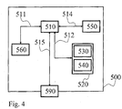
- Figure 4 shows an apparatus 500 according to one embodiment of the invention, comprising a nonvolatile memory 520, a processor 510 and a read and write memory 560.
- the memory 520 has a first memory part 530, in which a computer program for controlling the apparatus 500 is stored.
- the computer program in the memory part 530 for controlling the apparatus 500 can be an operating system.
- the apparatus 500 can be enclosed in, for example, a control unit, such as said control unit mentioned above.
- the data-processing unit 510 can comprise, for example, a microcomputer.
- the memory 520 also has a second memory part 540, in which a program for said cruise control system according to the invention is stored.
- the program is stored in a separate nonvolatile data storage medium 550, such as, for example, a CD or an exchangeable semiconductor memory.
- the program can be stored in an executable form or in a compressed state.
- the data-processing unit 510 runs a specific function, it should be clear that the data-processing unit 510 is running a specific part of the program stored in the memory 540 or a specific part of the program stored in the nonvolatile recording medium 550.
- the data-processing unit 510 is tailored for communication with the memory 550 through a data bus 514.
- the data-processing unit 510 is also tailored for communication with the memory 520 through a data bus 512.
- the data-processing unit 510 is tailored for communication with the memory 560 through a data bus 511.
- the data-processing unit 510 is also tailored for communication with a data port 590 by the use of a data bus 515.
Description
- The present invention relates to a method for controlling a cruise control in a vehicle, in accordance with the preamble of the accompanying
claim 1. The invention also relates to a vehicle cruise control system intended for such method for controlling said cruise control, in accordance with the preamble of the accompanying claim 11. - The present invention also relates to a computer program, computer program product and a storage medium for a computer all to be used with a computer for executing said method.
- Motor vehicles, such as cars, lorries, towing vehicles and buses, are often provided with a so-called cruise control system, also denominated speed control system, for automatically controlling the vehicle speed. Such a cruise control system comprises means, such as a speed sensor, for monitoring the actual vehicle speed. The cruise control system compares the actual vehicle speed with a set target speed. The target speed may for instance be entered into the cruise control system as the prevailing actual vehicle speed when a set switch is actuated by the driver. The cruise control system generates an error signal by comparing the actual vehicle speed with the target speed. The error signal is then for instance used to control an actuator coupled to the fuel pump or to the vehicle throttle in order to change the engine speed until the error signal is substantially zero, i.e. until the actual vehicle speed is equal to the target speed.
-
EP1439976 andUS6990401 disclose two examples of prior art where the cruise control system has been further developed. Here the cruise control system is a predictive cruise control system utilizing information about current vehicle position and upcoming road topography, that is for example gradients or elevation values for the coming road, in order to control throttle opening in such a way as to increase fuel efficiency.EP1885576 A1 also discloses a similar cruise control system. - The object of the present invention is to further develop such a cruise control system where information about current vehicle position and upcoming road topography is used by the cruise control for controlling vehicle speed.
- Thus, the primary object of the present invention is to present an improved method for cruise control which can avoid unnecessary accelerations in situations where earth gravitation can be used in order to within a reasonable future vehicle travelling accelerate the vehicle and regain vehicle speed. This is achieved by a method as discussed in the introduction, the characteristics of which are defined by
claim 1. The object is also achieved by a system as discussed in the introduction, the characteristics of which are defined by claim 11. - The method according to the invention is a method for controlling a cruise control during driving of a vehicle. Said method comprising the steps of:
- driving said vehicle with said cruise control active and set to maintain a vehicle set target speed;
- registering a first vehicle position when driving in an uphill slope of a hill where vehicle retardation has decreased vehicle speed to a first vehicle speed below said vehicle set target speed and where said retardation has decreased to zero or the vehicle has just started to accelerate in order to increase vehicle speed to said vehicle set target speed;
- registering a desired vehicle speed in a second position downhill of said crest at a first distance after said crest;
- based on said desired vehicle speed calculating a minimum vehicle speed at said crest with which said vehicle has to pass said crest in order to be able to reach said desired vehicle speed with a minimized or zero fuel consumption during said first distance;
- controlling vehicle speed during a second distance between said first vehicle position and said crest so that said vehicle reaches said minimum vehicle speed when passing said crest, and where a vehicle speed is maintained below said vehicle set target speed during said second distance.
- According to a first alternative embodiment of said invention said second vehicle position is one of;
- a predetermined vehicle traveling time from said crest,
- a predetermined distance from said crest,
- at the end of said downhill,
- at a distance from said crest where a vehicle traveling resistance is estimated to change from negative to positive.
- According to a further embodiment of said invention said method is characterized in further comprising the step of calculating a needed vehicle acceleration or retardation during said second distance in order to reach said minimum vehicle speed at said crest with a minimized fuel consumption during said second distance. According to another embodiment of said invention said method is characterized in further comprising the steps of:
- registering said first vehicle speed being just below a direct gear engagement vehicle speed;
- when having registered a predetermined vehicle condition setting said minimum vehicle speed to equal said direct gear engagement vehicle speed and accelerating the vehicle up to said minimum vehicle speed and engaging a direct gear;
- driving said vehicle with said direct gear engaged during remaining of said second distance.
- According to a further embodiment of the invention said predetermined vehicle condition comprises at least one of:
- said just below a direct gear engagement vehicle speed meaning a speed difference below 5km/h between said direct gear engagement vehicle speed and said first vehicle speed;
- said second distance is greater than a predetermined value;
- an estimated time interval for driving said vehicle with said direct gear engaged during said second distance is greater than a predetermined value.
- In another embodiment of the invention a maximum vehicle over speed is set for said vehicle cruise control, and where said maximum vehicle over speed is at least equal to or higher than said vehicle set target speed, and where said desired vehicle speed equals said maximum vehicle over speed.
- According to another embodiment of the invention a minimum vehicle under speed is set, having a predetermined relation to said vehicle set target speed. According to a further embodiment said predetermined relation is one of:
- said minimum vehicle under speed is a predetermined percentage of said vehicle set target speed;
- said minimum vehicle under speed is a predetermined amount below said vehicle set target speed.
- In a further embodiment of the invention said crest, said second position and said minimum vehicle speed are predicted with information about present vehicle position and coming road topography of said hill.
- According to a further embodiment of the invention if said second distance is shorter than a predetermined value, then said minimum vehicle speed is set to be equal to said first vehicle speed.
- The invention also relates to a vehicle cruise control system that comprises (includes, but is not necessarily limited to) a control unit, driver input interface, vehicle position identifying device, road topography identifying device. Said system is characterized in that said control unit is arranged to perform the above mentioned method steps and use information from said vehicle position identifying device and said road topography identifying device in order to calculate said minimum vehicle speed.
- Further advantageous embodiments of the invention emerge from the dependent patent claims following
patent claim 1. - The present invention will be described in greater detail below with reference to the accompanying drawings which, for the purpose of exemplification, shows further preferred embodiments of the invention and also the technical background, and in which:
-
Figure 1 to 3 diagrammatically show vehicle speed diagrams and corresponding driving conditions, and where said speed diagrams discloses cruise control according to different embodiments of the invention. -
Figure 4 discloses the invention applied in a computer arrangement. - A cruise control system for automatically controlling the vehicle speed can be arranged in a vehicle according to known art. Said cruise control system comprises a control unit for continually processing input signals and deliver output signals to, for example a propulsion unit control for controlling a propulsion unit and/or a brake control unit for controlling braking devices in said vehicle in order to maintain a set vehicle speed. Said vehicle cruise control system further comprises at least a driver input interface, vehicle position identifying device and road topography identifying device according to known art. Said control unit is arranged to perform steps of below described inventive functions with the use of information from said vehicle position identifying device and said road topography identifying device. Examples of road topography identifying device are route identifying devices and electronic map devices.
-
Figure 1 discloses avehicle 1, which travels over ahill 2. A cruise control in said vehicle is set to maintain vcc set target speed. Thus, said control unit in said cruise control system is arranged to maintain said vcc set target speed. A maximum vehicle over speed vbcc overspeed is also set in order for the control unit to initiate braking of said vehicle if vehicle speed approaches said vbcc overspeed. This functionality is known as such and is also called brake cruise control. Said maximum vehicle over speed vbcc overspeed for said vehicle cruise control can be set to be at least equal to or higher than said vehicle set target speed. In the shown example vbcc overspeed is higher than vcc set target speed. When the vehicle starts climbing said hill the vehicle speed eventually starts to decrease from said vcc set target speed due to incline of the uphillslope 3 and/or heavy loaded vehicle and/or lack of propulsion power, even though the propulsion unit of the vehicle delivers full power during uphill traveling. Eventually the incline of theuphill slope 3 starts to decrease and at a certain position A the vehicle retardation has decreased to zero. From position A and onwards the full power delivered by the propulsion unit is enough to start to accelerate the vehicle. Thus, vehicle speed starts to increase at position A. Position A also indicates where a minimum vehicle speed vmin occurred during the traveling over saidhill 2. According to known art and without knowledge of a coming crest at position B or the followingdownhill slope 5 said control unit will simply control said propulsion unit in order to regain vcc set target speed as soon as possible.Speed curve 4 discloses an example of this.Said curve 4 indicates that vcc set target speed is reached somewhere just after said position B. Since, after the position B, the vehicle is traveling downwards the inclination of thedownhill slope 5 further accelerates the vehicle passed said vcc set target speed and up to said vbcc overspeed. Thus, said control unit will initiate braking in order not to over speed said vbcc overspeed. A more fuel efficient way of controlling the vehicle speed when traveling over saidhill 2 would be according tocurve 6. In order to be able to control the vehicle speed according tocurve 6 said control unit has to have access to information about coming traveling route, such as in the mentioned prior art examplesEP1439976 andUS6990401 . The present invention relates to a further development of such a predictive cruise control system. - Referring to
figure 1 and according to an embodiment of the invention said control unit in said cruise control system is programmed to drive said vehicle with said cruise control active and set to maintain a vehicle set target speed vcc set target speed, and to perform the following steps: - registering a first vehicle position A when driving in said
uphill slope 3 of saidhill 2 where vehicle retardation has decreased vehicle speed to a first vehicle speed vmin below said vehicle set target speed and where said retardation has decreased to zero or the vehicle has just started to accelerate in order to increase vehicle speed to said vehicle set target speed; - registering a desired vehicle speed (in the shown example vbcc overspeed) in a second position C1 downhill of said crest at a first distance y1 after said crest B;
- based on said desired vehicle speed calculating a minimum vehicle speed vmin1 at said crest with which said vehicle has to pass said crest B in order to be able to reach said desired vehicle speed with a minimized or zero fuel consumption during said first distance y1;
- controlling vehicle speed during a second distance x between said first vehicle position A and said crest B so that said vehicle reaches said minimum vehicle speed vmin1 when passing said crest.
- Thus, the control unit will accelerate the vehicle during said second distance x only enough so that gravitational force during said first distance y1 in the
downhill slope 5 can accelerate the vehicle up to said desired vehicle speed. In this way braking of the vehicle during said downhill 5 and vehicle acceleration during said second distance x can be minimized. Note that in the example shown infigure 1 said first vehicle speed vmin is calculated to be equal to said minimum vehicle speed vmin1, thus the acceleration will be zero during said second distance x. As can be noted the vehicle speed is maintained below said vehicle set target speed during said second distance x. -
Figure 2 discloses anotherhill 22, which is identical to thehill 2 infigure 1 the first two thirds of the hill, that is up to a position z in thedownhill slope 25. Said downhillslope 25 levels out faster than said downhillslope 5. As can be seen said downhillslope 5 with its said first position C1 has also been drawn infigure 2 for easier comparison. When said invention is applied on thehill 22 shown infigure 2 said control unit will register a first vehicle position A that is the same as for saidhill 2. The same value for a first vehicle speed vmin is registered. Said control unit further registers a desired vehicle speed (also here vbcc overspeed) for a second position C2 downhill of said crest at a first distance y2 after said crest B. Thus, since this downhill slope levels out earlier this first distance y2 is shorter compared to y1 and consequently said C2 is positioned higher up compared to C1. This means that said desired vehicle speed has to be reached earlier compared to the example shown infigure 1 . Said control unit calculates a minimum vehicle speed vmin2 at said crest based on said desired vehicle speed at position C2, which speed has to be slightly higher compared to vmin1 in order to be able to reach said desired vehicle speed at C2. Said control unit will then control vehicle speed during a second distance x (which is equal to distance x infigure 1 ) between said first vehicle position A and said crest B so that said vehicle reaches said minimum vehicle speed vmin2 when passing said crest. In the example infigure 2 this means that the vehicle will be accelerated from vmin to vmin2. The control of the vehicle speed according to the invention is infigure 2 illustrated bycurve 26. - The benefit is that acceleration between position A and B is minimized and adapted to a coming downhill slope. Thus, coming downhill slopes are more effectively used for regaining vehicle speed up to desired vehicle speed. This leads to an decreased fuel consumption.
- If the downhill slope had been steeper than said downhill
slope 5 said control unit would have calculated a minimum vehicle speed for said crest B that is lower than said first vehicle speed vmin at position A. Thus, the vehicle would have to be retarded during said second distance x. In a further embodiment of the invention it is possible to set a minimum vehicle under speed. Said minimum vehicle under speed can be set manually or automatically by the control unit. Said control unit can be programmed to set said vehicle under speed with a predetermined relation to said vehicle set target speed vcc set target speed. Said predetermined relation can be one of for example: - said minimum vehicle under speed is a predetermined percentage of said vehicle set target speed;
- said minimum vehicle under speed is a predetermined amount of km/h below said vehicle set target speed.
- According to a further embodiment of the invention said second vehicle position C1 or C2 can be one of;
- a predetermined vehicle traveling time from said crest B,
- a predetermined distance from said crest,
- at the end of said downhill,
- at a distance from said crest where a vehicle traveling resistance is estimated to change from negative to positive. The last mentioned is the same position as where the vehicle speed increase falls to zero. In the
figures 1 to 3 , C1 or C2 is aiming at illustrating such positions. - In a further embodiment of the invention said control unit can be programmed to further perform the step of calculating a needed vehicle acceleration or retardation during said second distance x in order to reach said minimum vehicle speed at said crest with a minimized fuel consumption during said second distance. For example as illustrated in
figure 2 the acceleration up to vmin2 during distance x occurs mainly during the first half of said distance x. During second half of said distance x vehicle speed vmin2 is maintain. According to this embodiment of the invention a milder acceleration can be calculated and applied during said distance x, for example said control unit can accelerate the vehicle during whole distance x, that is with a lower acceleration and still reaching vmin2 at the crest B. -
Figure 3 discloses thesame hill 2 as infigure 1 , thus positions A, B, C1, x and y1 are the same infigure 2 and3 . The same vcc set target speed and vbcc overspeed are used in both examples. - A vehicle can comprise a propulsion unit drivingly connected to driven wheels of said vehicle via a transmission. A step geared transmission can comprise an input shaft, an intermediate shaft, which has at least one toothed gear meshing with a toothed gear on the input shaft, and main shaft with toothed gears, which mesh with toothed gears on the intermediate shaft. The main shaft is then further connected to an output shaft coupled to the driving wheels by way of a propeller shaft, for example. Each pair of toothed gears has a different gear ratio from another pair of gears in the gearbox. Different transmission ratios are obtained in that different pairs of gears transmit the torque from the propulsion unit to the driven wheels. Between two interacting and rotating toothed gears in such a transmission friction losses occur between the teeth of each of the toothed gears which are in engagement.
- In some step geared transmissions the highest gear (lowest gear ratio) is a so-called direct gear. This implies that the input shaft and the main shaft (or the output shaft) in the gearbox are directly connected to one another when the direct gear is engaged, which means that the torque is transmitted straight through the transmission without any gearing. It may alternatively be said that the transmission ratio is 1:1. Consequently no losses occur between meshing gears. In other words the direct gear is, all in all, a more fuel-saving gear than the other indirect gears, the transmission ratios of which are obtained through the pairs of toothed gears.
EP1494887 discloses an example of prior art with at transmission comprising a direct gear. - In another embodiment of the invention and with reference to
figure 3 said control unit is besides the above mentioned steps further programmed to perform the following steps: - registering said first vehicle speed vmin being just below a direct gear engagement vehicle speed at said first vehicle position A;
- when having registered a predetermined vehicle condition setting said minimum vehicle speed to equal said direct gear engagement vehicle speed and accelerating the vehicle up to said minimum vehicle speed vmin3 and engaging a direct gear;
- driving said vehicle with said direct gear engaged during remaining part of said second distance x.
- The benefit is that further fuel can be saved by driving said vehicle with a direct gear engaged instead of an indirect gear. There is a fuel cost related to the vehicle acceleration during said distance x. Thus, in order to initiate said acceleration and eventually engagement of said direct gear the right vehicle condition has to prevail, that is the amount of fuel saved by driving part of said distance x with a direct gear engaged must be estimated to be greater than the amount of extra fuel consumed due to said acceleration during distance x. Said predetermined vehicle condition can comprise for example at least one of:
- said just below a direct gear engagement vehicle speed vmin3 meaning a speed difference below 5km/h between said direct gear engagement vehicle speed and said first vehicle speed vmin;
- said second distance x is greater than a predetermined value;
- an estimated time interval for driving said vehicle with said direct gear engaged during said second distance x is greater than a predetermined value.
- The values of the four mentioned conditions are predetermined by the manufacturer of the vehicle. In a more advanced embodiment said control unit can be programmed to calculate an estimation of how much fuel that will be consumed if a direct gear is engaged compared to continuing driving with an indirect gear with said vmin1 up to said crest B. The outcome of said estimation decides if said direct gear will be engaged or not.
- Note that in the embodiments mentioned said control unit uses information about both present vehicle position and coming vehicle positions (or road topography of said hill) in order to be able to predict said crest, said second position and said minimum vehicle speed.
- Note also that in the mentioned embodiments during traveling said distances y1 or y2 fuel consumption is minimized by said control unit ordering zero propulsion power from the propulsion unit. Zero propulsion power includes for example both a propulsion unit drivingly connected to the driven wheels of the vehicle (for example engine braking) or not drivingly connected, that is for example freewheeling. Thus, only gravitational force accelerates the vehicle during traveling of said distances y1 or y2. Said calculation of minimum vehicle speed at said crest must consider if said propulsion unit will be drivingly connected or not drivingly connected to the driven wheels of the vehicle, since there is a significant difference in vehicle travel resistance between said two cases.
- In a further embodiment of the invention said control unit is programmed to equalize said minimum vehicle speed to said first vehicle speed vmin if said second distance x is shorter than a predetermined value. The main benefit of this is that further unnecessary accelerations can be avoided.
- In a further embodiment the vehicle does not have to be equipped with the possibility to set a maximum vehicle over speed vbcc overspeed in order to initiate braking of said vehicle if vehicle speed approaches said vbcc overspeed. Instead in such a vehicle not equipped with a brake cruise control said desired vehicle speed can be equal to said vehicle set target speed vcc set target speed.
-
Figure 4 shows anapparatus 500 according to one embodiment of the invention, comprising anonvolatile memory 520, aprocessor 510 and a read and writememory 560. Thememory 520 has afirst memory part 530, in which a computer program for controlling theapparatus 500 is stored. The computer program in thememory part 530 for controlling theapparatus 500 can be an operating system. - The
apparatus 500 can be enclosed in, for example, a control unit, such as said control unit mentioned above. The data-processing unit 510 can comprise, for example, a microcomputer. - The
memory 520 also has asecond memory part 540, in which a program for said cruise control system according to the invention is stored. In an alternative embodiment, the program is stored in a separate nonvolatiledata storage medium 550, such as, for example, a CD or an exchangeable semiconductor memory. The program can be stored in an executable form or in a compressed state. - When it is stated below that the data-
processing unit 510 runs a specific function, it should be clear that the data-processing unit 510 is running a specific part of the program stored in thememory 540 or a specific part of the program stored in thenonvolatile recording medium 550. - The data-
processing unit 510 is tailored for communication with thememory 550 through adata bus 514. The data-processing unit 510 is also tailored for communication with thememory 520 through adata bus 512. In addition, the data-processing unit 510 is tailored for communication with thememory 560 through adata bus 511. The data-processing unit 510 is also tailored for communication with adata port 590 by the use of adata bus 515. - The method according to the present invention can be executed by the data-
processing unit 510, by the data-processing unit 510 running the program stored in thememory 540 or the program stored in thenonvolatile recording medium 550. - The invention should not be deemed to be limited to the embodiments described above, but rather a number of further variants and modifications are conceivable within the scope of the following patent claims.
Claims (14)
- Method for controlling a vehicle cruise control comprising the steps of:- driving said vehicle with said cruise control active and set to maintain a vehicle set target speed (vcc set target speed);- registering a first vehicle position (A) when driving in an uphill slope of a hill where vehicle retardation has decreased vehicle speed to a first vehicle speed (vmin) below said vehicle set target speed and where said retardation has decreased to zero or the vehicle has just started to accelerate in order to increase vehicle speed to said vehicle set target speed;- registering a desired vehicle speed (vbcc overspeed) in a second position (C1, C2) downhill of a crest of said hill at a first distance (y1, y2) after said crest;- based on said desired vehicle speed calculating a minimum vehicle speed (vmin1, vmin2, vmin3) at said crest with which said vehicle has to pass said crest in order to be able to reach said desired vehicle speed with a minimized or zero fuel consumption during said first distance (y1, y2);characterised by the step of- controlling vehicle speed during a second distance (x) between said first vehicle position (A) and said crest (B) so that said vehicle reaches said minimum vehicle speed (vmin1, vmin2, vmin3) when passing said crest, and maintaining a vehicle speed below said vehicle set target speed during said second distance.
- The method as claimed in the claim 1,
characterized in that said second vehicle position (C1, C2) is one of;- a predetermined vehicle traveling time from said crest (B),- a predetermined distance from said crest,- at the end of said downhill,- at a distance from said crest where a vehicle traveling resistance is estimated to change from negative to positive. - The method as claimed in the claim 1,
characterized in further comprising the step of calculating a needed vehicle acceleration or retardation during said second distance (x) in order to reach said minimum vehicle speed at said crest with a minimized fuel consumption during said second distance. - The method as claimed in the claim 1,
characterized in further comprising the step of:- registering said first vehicle speed (vmin) being just below a direct gear engagement vehicle speed at said first vehicle position (A) ;- when having registered a predetermined vehicle condition setting said minimum vehicle speed to equal said direct gear engagement vehicle speed and accelerating the vehicle up to said minimum vehicle speed (vmin3) and engaging a direct gear;- driving said vehicle with said direct gear engaged during remaining part of said second distance (x). - The method as claimed in the preceding claim,
characterized in that said predetermined vehicle condition comprising at least one of:- said just below a direct gear engagement vehicle speed (vmin3) meaning a speed difference below 5km/h between said direct gear engagement vehicle speed and said first vehicle speed (vmin);- said second distance (x) is greater than a predetermined value;- an estimated time interval for driving said vehicle with said direct gear engaged during said second distance (x) is greater than a predetermined value. - The method as claimed in one of the preceding
claims, characterized in setting a maximum vehicle over speed (vbcc overspeed) for said vehicle cruise control, and where said maximum vehicle over speed is at least equal to or higher than said vehicle set target speed, and where said desired vehicle speed equals said maximum vehicle over speed. - The method as claimed in one of the preceding
claims, characterized in setting a minimum vehicle under speed, having a predetermined relation to said vehicle set target speed (vcc set target speed). - The method as claimed in the preceding claim,
characterized in that said predetermined relation is one of:- said minimum vehicle under speed is a predetermined percentage of said vehicle set target speed;- said minimum vehicle under speed is a predetermined amount below said vehicle set target speed. - The method as claimed in one of the preceding claims, characterized in that with information about present vehicle position and coming road topography of said hill predicting said crest, said second position and said minimum vehicle speed.
- The method as claimed in one of the preceding claims, characterized in that if said second distance (x) is shorter than a predetermined value, then said minimum vehicle speed is set to be equal to said first vehicle speed (vmin).
- A vehicle cruise control system comprising a control unit, driver input interface, vehicle position identifying device, road topography identifying device, characterized in that said control unit is arranged to perform method steps of claims 1 to 10 and use information from said vehicle position identifying device and said road topography identifying device in order to calculate said minimum vehicle speed (vmin1, vmin2, vmin3).
- A computer program comprising program code means for performing all the steps of any one of the claims 1 to 10 when said program is run on a computer.
- A computer program product comprising program code means stored on a computer readable medium for performing all steps of anyone of the claims 1 to 10 when said program product is run on a computer.
- A storage medium, such as a computer memory (520) or a nonvolatile data storage medium (550), for use in a computing environment, the memory comprising a computer readable program code to perform the method of the claims 1 to 10.
Applications Claiming Priority (1)
| Application Number | Priority Date | Filing Date | Title |
|---|---|---|---|
| PCT/SE2009/050862 WO2011002367A1 (en) | 2009-07-02 | 2009-07-02 | Method and system for controlling a vehicle cruise control |
Publications (3)
| Publication Number | Publication Date |
|---|---|
| EP2448784A1 EP2448784A1 (en) | 2012-05-09 |
| EP2448784A4 EP2448784A4 (en) | 2018-04-25 |
| EP2448784B1 true EP2448784B1 (en) | 2019-03-13 |
Family
ID=43411260
Family Applications (1)
| Application Number | Title | Priority Date | Filing Date |
|---|---|---|---|
| EP09846913.3A Active EP2448784B1 (en) | 2009-07-02 | 2009-07-02 | Method and system for controlling a vehicle cruise control |
Country Status (7)
| Country | Link |
|---|---|
| US (1) | US9096229B2 (en) |
| EP (1) | EP2448784B1 (en) |
| JP (1) | JP5686382B2 (en) |
| CN (1) | CN102470867B (en) |
| BR (1) | BRPI0925298B1 (en) |
| RU (1) | RU2521931C2 (en) |
| WO (1) | WO2011002367A1 (en) |
Families Citing this family (34)
| Publication number | Priority date | Publication date | Assignee | Title |
|---|---|---|---|---|
| DE102009046340A1 (en) * | 2009-11-03 | 2011-05-05 | Zf Friedrichshafen Ag | Method for controlling a rolling or sailing function of a vehicle |
| SE535599C2 (en) * | 2011-02-23 | 2012-10-09 | Scania Cv Ab | Procedure and system for controlling cruise control |
| SE536150C2 (en) * | 2011-05-16 | 2013-06-04 | Scania Cv Ab | Driver interaction in economic cruising |
| US9108639B2 (en) * | 2011-12-22 | 2015-08-18 | Scania Cv Ab | Method and module for controlling a vehicle's speed based on rules and/or costs |
| GB2508461B (en) * | 2012-08-16 | 2014-12-17 | Jaguar Land Rover Ltd | Vehicle speed control system and method employing torque balancing |
| GB2505028B (en) * | 2012-08-16 | 2014-12-10 | Jaguar Land Rover Ltd | Vehicle speed control system and method |
| FR2996817B1 (en) * | 2012-10-17 | 2014-10-31 | Peugeot Citroen Automobiles Sa | METHOD FOR CONTROLLING A PILOTED AUTOMATIC OR MANUAL SPEED BOX |
| WO2014083631A1 (en) * | 2012-11-28 | 2014-06-05 | トヨタ自動車株式会社 | Vehicle travel control device |
| US20150066327A1 (en) * | 2013-08-30 | 2015-03-05 | Ford Global Technologies, Llc | Eco-mode cruise control |
| GB2519533B (en) * | 2013-10-23 | 2018-04-04 | Jaguar Land Rover Ltd | Vehicle speed control system |
| DE102013223829A1 (en) | 2013-11-21 | 2015-05-21 | Robert Bosch Gmbh | Method for predictively influencing a vehicle speed |
| DE102013223844A1 (en) | 2013-11-21 | 2015-05-21 | Robert Bosch Gmbh | Method for predictively influencing a vehicle speed |
| DE102015001818A1 (en) | 2014-02-19 | 2015-09-03 | Cummins Inc. | Travel resistance management for land vehicles and / or related operator notification |
| US9272621B2 (en) * | 2014-04-24 | 2016-03-01 | Cummins Inc. | Systems and methods for vehicle speed management |
| US9835248B2 (en) | 2014-05-28 | 2017-12-05 | Cummins Inc. | Systems and methods for dynamic gear state and vehicle speed management |
| US9393963B2 (en) | 2014-09-19 | 2016-07-19 | Paccar Inc | Predictive cruise control system with advanced operator control and feedback |
| US9994220B2 (en) * | 2015-01-05 | 2018-06-12 | Nissan Motor Co., Ltd. | Target vehicle speed generating device and driving control device |
| US9849880B2 (en) | 2015-04-13 | 2017-12-26 | Ford Global Technologies, Llc | Method and system for vehicle cruise control |
| US10124784B2 (en) | 2015-04-13 | 2018-11-13 | Ford Global Technologies, Llc | Method and system for controlling shifting of a vehicle in cruise control |
| EP3341256B1 (en) * | 2015-08-28 | 2019-03-20 | Volvo Truck Corporation | A method and a system for controlling vehicle speed |
| US20170291605A1 (en) * | 2016-04-12 | 2017-10-12 | GM Global Technology Operations LLC | Optimized fuel economy during cruise control using topography data |
| GB2552021B (en) * | 2016-07-08 | 2019-08-28 | Jaguar Land Rover Ltd | Improvements in vehicle speed control |
| DE102016220247A1 (en) | 2016-10-17 | 2018-04-19 | Zf Friedrichshafen Ag | Method and control device for operating a vehicle |
| CN110225854B (en) * | 2017-01-25 | 2022-09-20 | 卡明斯公司 | System and method for predictive gear shift and integrated predictive cruise control |
| KR102272761B1 (en) * | 2017-02-08 | 2021-07-05 | 현대자동차주식회사 | Vehicle and control method thereof |
| CN109478069A (en) * | 2017-04-13 | 2019-03-15 | 松下电器产业株式会社 | The control method and electric vehicle of electric vehicle |
| JP7062884B2 (en) | 2017-05-12 | 2022-05-09 | いすゞ自動車株式会社 | Vehicle control unit |
| US10336311B2 (en) * | 2017-06-13 | 2019-07-02 | Cnh Industrial America Llc | System and method for controlling the speed of a work vehicle during downhill operation |
| CN109895769A (en) * | 2017-12-11 | 2019-06-18 | 郑州宇通客车股份有限公司 | Hybrid vehicle and constant-speed-cruise control method and control system |
| KR102347651B1 (en) * | 2017-12-11 | 2022-01-06 | 현대자동차주식회사 | Method for Chassis Integration Control Based on Mountain Road and Vehicle thereof |
| GB2569974B (en) * | 2018-01-05 | 2020-04-15 | Jaguar Land Rover Ltd | Controller and method |
| US20200269689A1 (en) * | 2019-02-22 | 2020-08-27 | GM Global Technology Operations LLC | Eco-cruise: fuel-economy optimized cruise control |
| US11052896B2 (en) * | 2019-06-18 | 2021-07-06 | GM Global Technology Operations LLC | Predictive grade optimization in cruise control |
| CN113879301B (en) * | 2021-10-19 | 2023-06-23 | 中寰卫星导航通信有限公司 | Vehicle control method, device, equipment and storage medium |
Family Cites Families (34)
| Publication number | Priority date | Publication date | Assignee | Title |
|---|---|---|---|---|
| JPS61278427A (en) * | 1985-06-03 | 1986-12-09 | Mazda Motor Corp | Running control device for vehicle |
| RU2006385C1 (en) * | 1991-10-14 | 1994-01-30 | Научно-исследовательский институт радиоприборостроения | Device for automatic control of car movement in emergency situations |
| RU2029794C1 (en) * | 1992-07-25 | 1995-02-27 | Татьяна Казимировна Ляхович | Storage medium for longitudinal magnetic recording medium |
| JP3203976B2 (en) * | 1994-09-05 | 2001-09-04 | 日産自動車株式会社 | Vehicle driving force control device |
| US5839534A (en) * | 1995-03-01 | 1998-11-24 | Eaton Vorad Technologies, Llc | System and method for intelligent cruise control using standard engine control modes |
| SE504467C2 (en) * | 1995-06-07 | 1997-02-17 | Volvo Ab | Cruise control device for motor vehicles |
| US5868214A (en) * | 1995-08-29 | 1999-02-09 | Cummins Engine Company, Inc. | Cruise control governor using optimal droop selection logic |
| JPH11291789A (en) * | 1998-04-07 | 1999-10-26 | Nissan Motor Co Ltd | Running control device for vehicle |
| US5944766A (en) * | 1998-04-09 | 1999-08-31 | White; Lee S | Cruise control economizer |
| US6374173B1 (en) * | 1999-05-28 | 2002-04-16 | Freightliner Llc | Terrain adaptive cruise control |
| KR100325203B1 (en) * | 1999-07-08 | 2002-02-25 | 이계안 | Method for controlling automatic cruise of vehicle |
| US6370472B1 (en) * | 2000-09-15 | 2002-04-09 | Mirenco, Inc. | Method and apparatus for reducing unwanted vehicle emissions using satellite navigation |
| SE520400C2 (en) * | 2001-10-31 | 2003-07-08 | Volvo Lastvagnar Ab | Cruise control in motor vehicles |
| SE521788C2 (en) * | 2002-04-04 | 2003-12-09 | Volvo Lastvagnar Ab | Power units for motor vehicles |
| US20030221886A1 (en) * | 2002-05-30 | 2003-12-04 | Petrie Alfred E. | Veritable perimeter cruise control |
| US6990401B2 (en) * | 2002-10-04 | 2006-01-24 | Daimlerchrysler Ag | Predictive speed control for a motor vehicle |
| JP4554393B2 (en) * | 2005-02-17 | 2010-09-29 | 日野自動車株式会社 | Auto cruise control device |
| SE529578C2 (en) * | 2005-04-04 | 2007-09-25 | Scania Cv Abp | A method and system for controlling the operation of a vehicle |
| JP4792801B2 (en) * | 2005-04-21 | 2011-10-12 | 株式会社アドヴィックス | Vehicle speed control device |
| US20060293822A1 (en) * | 2005-06-27 | 2006-12-28 | Freightliner Llc | Predictive control method and apparatus for vehicle automatic transmission |
| JP4707106B2 (en) * | 2005-12-02 | 2011-06-22 | Udトラックス株式会社 | Fuel-saving driving system |
| DE102006001818B4 (en) | 2006-01-13 | 2017-02-02 | Man Truck & Bus Ag | Method and device for driver assistance during the driving operation of a commercial vehicle |
| JP4713408B2 (en) * | 2006-06-07 | 2011-06-29 | トヨタ自動車株式会社 | Vehicle control device |
| EP2148800B1 (en) * | 2007-04-20 | 2016-11-23 | Volvo Lastvagnar AB | Method for increasing active duration time of an automatic freewheeling function in a vehicle |
| JP4457136B2 (en) * | 2007-09-27 | 2010-04-28 | 日立オートモティブシステムズ株式会社 | Travel control system |
| US8214122B2 (en) * | 2008-04-10 | 2012-07-03 | GM Global Technology Operations LLC | Energy economy mode using preview information |
| US8788173B2 (en) * | 2008-07-07 | 2014-07-22 | Robert Horton Transou, JR. | Fuel saver speed control |
| DE102008038078A1 (en) * | 2008-07-26 | 2009-05-14 | Daimler Ag | Method for operating vehicle, involves displaying operational conditions of temperature function on displaying device such that operational conditions are assigned to past, current and future sections of distance profile |
| US8700256B2 (en) * | 2008-08-22 | 2014-04-15 | Daimler Trucks North America Llc | Vehicle disturbance estimator and method |
| JP5109915B2 (en) * | 2008-10-09 | 2012-12-26 | トヨタ自動車株式会社 | Driving support device |
| JP4806704B2 (en) * | 2008-12-04 | 2011-11-02 | 本田技研工業株式会社 | Vehicle travel control device |
| WO2010071498A1 (en) * | 2008-12-19 | 2010-06-24 | Volvo Lastvagnar Ab | Method and device for controlling a vehicle cruise control |
| EP2507104B1 (en) * | 2009-11-30 | 2015-04-08 | Volvo Lastvagnar AB | Method and system for controlling a vehicle cruise control |
| WO2011076226A1 (en) * | 2009-12-21 | 2011-06-30 | Volvo Lastvagnar Ab | Method and system for controlling a vehicle cruise control |
-
2009
- 2009-07-02 WO PCT/SE2009/050862 patent/WO2011002367A1/en active Application Filing
- 2009-07-02 EP EP09846913.3A patent/EP2448784B1/en active Active
- 2009-07-02 JP JP2012518510A patent/JP5686382B2/en active Active
- 2009-07-02 CN CN200980160278.2A patent/CN102470867B/en active Active
- 2009-07-02 US US13/381,957 patent/US9096229B2/en active Active
- 2009-07-02 RU RU2012103384/11A patent/RU2521931C2/en active
- 2009-07-02 BR BRPI0925298-3A patent/BRPI0925298B1/en active IP Right Grant
Non-Patent Citations (1)
| Title |
|---|
| None * |
Also Published As
| Publication number | Publication date |
|---|---|
| RU2012103384A (en) | 2013-08-10 |
| US20130030668A1 (en) | 2013-01-31 |
| JP2012532057A (en) | 2012-12-13 |
| BRPI0925298A2 (en) | 2020-08-11 |
| BRPI0925298B1 (en) | 2021-03-30 |
| JP5686382B2 (en) | 2015-03-18 |
| WO2011002367A1 (en) | 2011-01-06 |
| RU2521931C2 (en) | 2014-07-10 |
| CN102470867B (en) | 2015-04-08 |
| US9096229B2 (en) | 2015-08-04 |
| EP2448784A1 (en) | 2012-05-09 |
| CN102470867A (en) | 2012-05-23 |
| EP2448784A4 (en) | 2018-04-25 |
Similar Documents
| Publication | Publication Date | Title |
|---|---|---|
| EP2448784B1 (en) | Method and system for controlling a vehicle cruise control | |
| EP2507104B1 (en) | Method and system for controlling a vehicle cruise control | |
| EP2516194B1 (en) | Method and system for controlling a vehicle cruise control | |
| US6299563B1 (en) | Control system for hybrid vehicle | |
| EP3575130A1 (en) | Vehicle control system and method of controlling the same, and braking device | |
| CN102421652B (en) | Method and device for controlling an automatic freewheeling function in a vehicle | |
| JP2006298369A5 (en) | ||
| EP2212148B1 (en) | A method for a more efficient use of a combustion engine in a vehicle provided with an automatic step gear transmission | |
| CN111194286B (en) | Vehicle control method and control device | |
| CN110462263B (en) | Method and device for controlling gear shift in vehicle with transmission | |
| CN107110340B (en) | Coast stop control device | |
| KR101993434B1 (en) | Control of preparatory measures in a vehicle | |
| EP3383715B1 (en) | A method and system for gear shifting in a hybrid powertrain | |
| CN113700847B (en) | AMT (automated mechanical transmission) -matched commercial vehicle low-speed control method, device and equipment | |
| CN110446643B (en) | Travel control device, vehicle, and travel control method | |
| CN116113556A (en) | Control method of series hybrid vehicle and series hybrid vehicle | |
| JP6994007B2 (en) | Vehicle control device |
Legal Events
| Date | Code | Title | Description |
|---|---|---|---|
| PUAI | Public reference made under article 153(3) epc to a published international application that has entered the european phase |
Free format text: ORIGINAL CODE: 0009012 |
|
| 17P | Request for examination filed |
Effective date: 20120202 |
|
| AK | Designated contracting states |
Kind code of ref document: A1 Designated state(s): AT BE BG CH CY CZ DE DK EE ES FI FR GB GR HR HU IE IS IT LI LT LU LV MC MK MT NL NO PL PT RO SE SI SK SM TR |
|
| RIN1 | Information on inventor provided before grant (corrected) |
Inventor name: BJERNETUN, JOHAN Inventor name: ERIKSSON, ANDERS |
|
| DAX | Request for extension of the european patent (deleted) | ||
| RA4 | Supplementary search report drawn up and despatched (corrected) |
Effective date: 20180327 |
|
| RIC1 | Information provided on ipc code assigned before grant |
Ipc: B60K 31/00 20060101AFI20180321BHEP Ipc: B60W 50/00 20060101ALN20180321BHEP Ipc: B60W 30/14 20060101ALI20180321BHEP Ipc: B60W 10/11 20120101ALI20180321BHEP Ipc: F16H 59/36 20060101ALI20180321BHEP Ipc: B60W 10/06 20060101ALI20180321BHEP Ipc: B60W 10/10 20120101ALI20180321BHEP |
|
| RIC1 | Information provided on ipc code assigned before grant |
Ipc: B60W 10/11 20120101ALI20180925BHEP Ipc: B60W 10/10 20120101ALI20180925BHEP Ipc: B60W 50/00 20060101ALN20180925BHEP Ipc: B60W 10/06 20060101ALI20180925BHEP Ipc: B60W 30/14 20060101ALI20180925BHEP Ipc: B60K 31/00 20060101AFI20180925BHEP Ipc: F16H 59/36 20060101ALI20180925BHEP |
|
| GRAP | Despatch of communication of intention to grant a patent |
Free format text: ORIGINAL CODE: EPIDOSNIGR1 |
|
| STAA | Information on the status of an ep patent application or granted ep patent |
Free format text: STATUS: GRANT OF PATENT IS INTENDED |
|
| RIC1 | Information provided on ipc code assigned before grant |
Ipc: B60W 10/11 20120101ALI20181018BHEP Ipc: F16H 59/36 20060101ALI20181018BHEP Ipc: B60W 50/00 20060101ALN20181018BHEP Ipc: B60W 10/06 20060101ALI20181018BHEP Ipc: B60K 31/00 20060101AFI20181018BHEP Ipc: B60W 10/10 20120101ALI20181018BHEP Ipc: B60W 30/14 20060101ALI20181018BHEP |
|
| INTG | Intention to grant announced |
Effective date: 20181106 |
|
| GRAS | Grant fee paid |
Free format text: ORIGINAL CODE: EPIDOSNIGR3 |
|
| GRAA | (expected) grant |
Free format text: ORIGINAL CODE: 0009210 |
|
| STAA | Information on the status of an ep patent application or granted ep patent |
Free format text: STATUS: THE PATENT HAS BEEN GRANTED |
|
| RIN1 | Information on inventor provided before grant (corrected) |
Inventor name: BJERNETUN, JOHAN Inventor name: ERIKSSON, ANDERS |
|
| AK | Designated contracting states |
Kind code of ref document: B1 Designated state(s): AT BE BG CH CY CZ DE DK EE ES FI FR GB GR HR HU IE IS IT LI LT LU LV MC MK MT NL NO PL PT RO SE SI SK SM TR |
|
| REG | Reference to a national code |
Ref country code: GB Ref legal event code: FG4D |
|
| REG | Reference to a national code |
Ref country code: CH Ref legal event code: EP Ref country code: AT Ref legal event code: REF Ref document number: 1107231 Country of ref document: AT Kind code of ref document: T Effective date: 20190315 |
|
| REG | Reference to a national code |
Ref country code: IE Ref legal event code: FG4D |
|
| REG | Reference to a national code |
Ref country code: DE Ref legal event code: R096 Ref document number: 602009057480 Country of ref document: DE |
|
| REG | Reference to a national code |
Ref country code: SE Ref legal event code: TRGR |
|
| REG | Reference to a national code |
Ref country code: NL Ref legal event code: FP |
|
| REG | Reference to a national code |
Ref country code: LT Ref legal event code: MG4D |
|
| PG25 | Lapsed in a contracting state [announced via postgrant information from national office to epo] |
Ref country code: FI Free format text: LAPSE BECAUSE OF FAILURE TO SUBMIT A TRANSLATION OF THE DESCRIPTION OR TO PAY THE FEE WITHIN THE PRESCRIBED TIME-LIMIT Effective date: 20190313 Ref country code: NO Free format text: LAPSE BECAUSE OF FAILURE TO SUBMIT A TRANSLATION OF THE DESCRIPTION OR TO PAY THE FEE WITHIN THE PRESCRIBED TIME-LIMIT Effective date: 20190613 Ref country code: LT Free format text: LAPSE BECAUSE OF FAILURE TO SUBMIT A TRANSLATION OF THE DESCRIPTION OR TO PAY THE FEE WITHIN THE PRESCRIBED TIME-LIMIT Effective date: 20190313 |
|
| PG25 | Lapsed in a contracting state [announced via postgrant information from national office to epo] |
Ref country code: BG Free format text: LAPSE BECAUSE OF FAILURE TO SUBMIT A TRANSLATION OF THE DESCRIPTION OR TO PAY THE FEE WITHIN THE PRESCRIBED TIME-LIMIT Effective date: 20190613 Ref country code: GR Free format text: LAPSE BECAUSE OF FAILURE TO SUBMIT A TRANSLATION OF THE DESCRIPTION OR TO PAY THE FEE WITHIN THE PRESCRIBED TIME-LIMIT Effective date: 20190614 Ref country code: HR Free format text: LAPSE BECAUSE OF FAILURE TO SUBMIT A TRANSLATION OF THE DESCRIPTION OR TO PAY THE FEE WITHIN THE PRESCRIBED TIME-LIMIT Effective date: 20190313 Ref country code: LV Free format text: LAPSE BECAUSE OF FAILURE TO SUBMIT A TRANSLATION OF THE DESCRIPTION OR TO PAY THE FEE WITHIN THE PRESCRIBED TIME-LIMIT Effective date: 20190313 |
|
| REG | Reference to a national code |
Ref country code: AT Ref legal event code: MK05 Ref document number: 1107231 Country of ref document: AT Kind code of ref document: T Effective date: 20190313 |
|
| PG25 | Lapsed in a contracting state [announced via postgrant information from national office to epo] |
Ref country code: RO Free format text: LAPSE BECAUSE OF FAILURE TO SUBMIT A TRANSLATION OF THE DESCRIPTION OR TO PAY THE FEE WITHIN THE PRESCRIBED TIME-LIMIT Effective date: 20190313 Ref country code: IT Free format text: LAPSE BECAUSE OF FAILURE TO SUBMIT A TRANSLATION OF THE DESCRIPTION OR TO PAY THE FEE WITHIN THE PRESCRIBED TIME-LIMIT Effective date: 20190313 Ref country code: SK Free format text: LAPSE BECAUSE OF FAILURE TO SUBMIT A TRANSLATION OF THE DESCRIPTION OR TO PAY THE FEE WITHIN THE PRESCRIBED TIME-LIMIT Effective date: 20190313 Ref country code: CZ Free format text: LAPSE BECAUSE OF FAILURE TO SUBMIT A TRANSLATION OF THE DESCRIPTION OR TO PAY THE FEE WITHIN THE PRESCRIBED TIME-LIMIT Effective date: 20190313 Ref country code: EE Free format text: LAPSE BECAUSE OF FAILURE TO SUBMIT A TRANSLATION OF THE DESCRIPTION OR TO PAY THE FEE WITHIN THE PRESCRIBED TIME-LIMIT Effective date: 20190313 Ref country code: PT Free format text: LAPSE BECAUSE OF FAILURE TO SUBMIT A TRANSLATION OF THE DESCRIPTION OR TO PAY THE FEE WITHIN THE PRESCRIBED TIME-LIMIT Effective date: 20190713 Ref country code: ES Free format text: LAPSE BECAUSE OF FAILURE TO SUBMIT A TRANSLATION OF THE DESCRIPTION OR TO PAY THE FEE WITHIN THE PRESCRIBED TIME-LIMIT Effective date: 20190313 |
|
| PG25 | Lapsed in a contracting state [announced via postgrant information from national office to epo] |
Ref country code: SM Free format text: LAPSE BECAUSE OF FAILURE TO SUBMIT A TRANSLATION OF THE DESCRIPTION OR TO PAY THE FEE WITHIN THE PRESCRIBED TIME-LIMIT Effective date: 20190313 Ref country code: PL Free format text: LAPSE BECAUSE OF FAILURE TO SUBMIT A TRANSLATION OF THE DESCRIPTION OR TO PAY THE FEE WITHIN THE PRESCRIBED TIME-LIMIT Effective date: 20190313 |
|
| REG | Reference to a national code |
Ref country code: DE Ref legal event code: R097 Ref document number: 602009057480 Country of ref document: DE |
|
| PG25 | Lapsed in a contracting state [announced via postgrant information from national office to epo] |
Ref country code: AT Free format text: LAPSE BECAUSE OF FAILURE TO SUBMIT A TRANSLATION OF THE DESCRIPTION OR TO PAY THE FEE WITHIN THE PRESCRIBED TIME-LIMIT Effective date: 20190313 Ref country code: IS Free format text: LAPSE BECAUSE OF FAILURE TO SUBMIT A TRANSLATION OF THE DESCRIPTION OR TO PAY THE FEE WITHIN THE PRESCRIBED TIME-LIMIT Effective date: 20190713 |
|
| PLBE | No opposition filed within time limit |
Free format text: ORIGINAL CODE: 0009261 |
|
| STAA | Information on the status of an ep patent application or granted ep patent |
Free format text: STATUS: NO OPPOSITION FILED WITHIN TIME LIMIT |
|
| PG25 | Lapsed in a contracting state [announced via postgrant information from national office to epo] |
Ref country code: DK Free format text: LAPSE BECAUSE OF FAILURE TO SUBMIT A TRANSLATION OF THE DESCRIPTION OR TO PAY THE FEE WITHIN THE PRESCRIBED TIME-LIMIT Effective date: 20190313 |
|
| 26N | No opposition filed |
Effective date: 20191216 |
|
| PG25 | Lapsed in a contracting state [announced via postgrant information from national office to epo] |
Ref country code: SI Free format text: LAPSE BECAUSE OF FAILURE TO SUBMIT A TRANSLATION OF THE DESCRIPTION OR TO PAY THE FEE WITHIN THE PRESCRIBED TIME-LIMIT Effective date: 20190313 Ref country code: MC Free format text: LAPSE BECAUSE OF FAILURE TO SUBMIT A TRANSLATION OF THE DESCRIPTION OR TO PAY THE FEE WITHIN THE PRESCRIBED TIME-LIMIT Effective date: 20190313 |
|
| REG | Reference to a national code |
Ref country code: CH Ref legal event code: PL |
|
| GBPC | Gb: european patent ceased through non-payment of renewal fee |
Effective date: 20190702 |
|
| PG25 | Lapsed in a contracting state [announced via postgrant information from national office to epo] |
Ref country code: TR Free format text: LAPSE BECAUSE OF FAILURE TO SUBMIT A TRANSLATION OF THE DESCRIPTION OR TO PAY THE FEE WITHIN THE PRESCRIBED TIME-LIMIT Effective date: 20190313 |
|
| REG | Reference to a national code |
Ref country code: BE Ref legal event code: MM Effective date: 20190731 |
|
| PG25 | Lapsed in a contracting state [announced via postgrant information from national office to epo] |
Ref country code: GB Free format text: LAPSE BECAUSE OF NON-PAYMENT OF DUE FEES Effective date: 20190702 |
|
| PG25 | Lapsed in a contracting state [announced via postgrant information from national office to epo] |
Ref country code: CH Free format text: LAPSE BECAUSE OF NON-PAYMENT OF DUE FEES Effective date: 20190731 Ref country code: LI Free format text: LAPSE BECAUSE OF NON-PAYMENT OF DUE FEES Effective date: 20190731 Ref country code: BE Free format text: LAPSE BECAUSE OF NON-PAYMENT OF DUE FEES Effective date: 20190731 Ref country code: LU Free format text: LAPSE BECAUSE OF NON-PAYMENT OF DUE FEES Effective date: 20190702 |
|
| PG25 | Lapsed in a contracting state [announced via postgrant information from national office to epo] |
Ref country code: IE Free format text: LAPSE BECAUSE OF NON-PAYMENT OF DUE FEES Effective date: 20190702 |
|
| PG25 | Lapsed in a contracting state [announced via postgrant information from national office to epo] |
Ref country code: CY Free format text: LAPSE BECAUSE OF FAILURE TO SUBMIT A TRANSLATION OF THE DESCRIPTION OR TO PAY THE FEE WITHIN THE PRESCRIBED TIME-LIMIT Effective date: 20190313 |
|
| PG25 | Lapsed in a contracting state [announced via postgrant information from national office to epo] |
Ref country code: MT Free format text: LAPSE BECAUSE OF FAILURE TO SUBMIT A TRANSLATION OF THE DESCRIPTION OR TO PAY THE FEE WITHIN THE PRESCRIBED TIME-LIMIT Effective date: 20190313 Ref country code: HU Free format text: LAPSE BECAUSE OF FAILURE TO SUBMIT A TRANSLATION OF THE DESCRIPTION OR TO PAY THE FEE WITHIN THE PRESCRIBED TIME-LIMIT; INVALID AB INITIO Effective date: 20090702 |
|
| PG25 | Lapsed in a contracting state [announced via postgrant information from national office to epo] |
Ref country code: MK Free format text: LAPSE BECAUSE OF FAILURE TO SUBMIT A TRANSLATION OF THE DESCRIPTION OR TO PAY THE FEE WITHIN THE PRESCRIBED TIME-LIMIT Effective date: 20190313 |
|
| PGFP | Annual fee paid to national office [announced via postgrant information from national office to epo] |
Ref country code: NL Payment date: 20230726 Year of fee payment: 15 |
|
| PGFP | Annual fee paid to national office [announced via postgrant information from national office to epo] |
Ref country code: SE Payment date: 20230726 Year of fee payment: 15 Ref country code: FR Payment date: 20230725 Year of fee payment: 15 Ref country code: DE Payment date: 20230726 Year of fee payment: 15 |