EP2448075A1 - Apparatus for protecting direct current branch circuit - Google Patents
Apparatus for protecting direct current branch circuit Download PDFInfo
- Publication number
- EP2448075A1 EP2448075A1 EP10792024A EP10792024A EP2448075A1 EP 2448075 A1 EP2448075 A1 EP 2448075A1 EP 10792024 A EP10792024 A EP 10792024A EP 10792024 A EP10792024 A EP 10792024A EP 2448075 A1 EP2448075 A1 EP 2448075A1
- Authority
- EP
- European Patent Office
- Prior art keywords
- circuit
- current
- circuit breaker
- load
- branch
- Prior art date
- Legal status (The legal status is an assumption and is not a legal conclusion. Google has not performed a legal analysis and makes no representation as to the accuracy of the status listed.)
- Granted
Links
Images


Classifications
-
- H—ELECTRICITY
- H02—GENERATION; CONVERSION OR DISTRIBUTION OF ELECTRIC POWER
- H02J—ELECTRIC POWER NETWORKS; CIRCUIT ARRANGEMENTS OR SYSTEMS FOR SUPPLYING OR DISTRIBUTING ELECTRIC POWER; SYSTEMS FOR STORING ELECTRIC ENERGY
- H02J1/00—Circuit arrangements for DC mains or DC distribution networks
- H02J1/06—Two-wire DC power distribution systems
-
- H—ELECTRICITY
- H02—GENERATION; CONVERSION OR DISTRIBUTION OF ELECTRIC POWER
- H02H—EMERGENCY PROTECTIVE CIRCUIT ARRANGEMENTS
- H02H3/00—Emergency protective circuit arrangements for automatic disconnection directly responsive to an undesired change from normal electric working condition with or without subsequent reconnection ; integrated protection
- H02H3/08—Emergency protective circuit arrangements for automatic disconnection directly responsive to an undesired change from normal electric working condition with or without subsequent reconnection ; integrated protection responsive to excess current
- H02H3/087—Emergency protective circuit arrangements for automatic disconnection directly responsive to an undesired change from normal electric working condition with or without subsequent reconnection ; integrated protection responsive to excess current for DC applications
-
- H—ELECTRICITY
- H01—ELECTRIC ELEMENTS
- H01H—ELECTRIC SWITCHES; RELAYS; SELECTORS; EMERGENCY PROTECTIVE DEVICES
- H01H71/00—Details of the protective switches or relays covered by groups H01H73/00 - H01H83/00
- H01H71/10—Operating or release mechanisms
- H01H71/12—Automatic release mechanisms with or without manual release
- H01H71/123—Automatic release mechanisms with or without manual release using a solid-state trip unit
-
- H—ELECTRICITY
- H02—GENERATION; CONVERSION OR DISTRIBUTION OF ELECTRIC POWER
- H02H—EMERGENCY PROTECTIVE CIRCUIT ARRANGEMENTS
- H02H3/00—Emergency protective circuit arrangements for automatic disconnection directly responsive to an undesired change from normal electric working condition with or without subsequent reconnection ; integrated protection
- H02H3/08—Emergency protective circuit arrangements for automatic disconnection directly responsive to an undesired change from normal electric working condition with or without subsequent reconnection ; integrated protection responsive to excess current
- H02H3/10—Emergency protective circuit arrangements for automatic disconnection directly responsive to an undesired change from normal electric working condition with or without subsequent reconnection ; integrated protection responsive to excess current additionally responsive to some other abnormal electrical conditions
-
- H—ELECTRICITY
- H02—GENERATION; CONVERSION OR DISTRIBUTION OF ELECTRIC POWER
- H02H—EMERGENCY PROTECTIVE CIRCUIT ARRANGEMENTS
- H02H7/00—Emergency protective circuit arrangements specially adapted for specific types of electric machines or apparatus or for sectionalised protection of cable or line systems, and effecting automatic switching in the event of an undesired change from normal working conditions
- H02H7/26—Sectionalised protection of cable or line systems, e.g. for disconnecting a section on which a short-circuit, earth fault, or arc discharge has occured
Definitions
- the invention relates to a DC branch circuit protecting device.
- a power supply device 100 as a conventional power supply device equipped with a protective function for protecting a load from an overcurrent, provided with a fuse F along an output end of a constant-voltage source E with which loads L1-L4 are connected in parallel through switches S1-S4, respectively.
- a conventional power supply device 101 is provided with a multipoint connector 102 connected with a plurality of load circuits as shown in FIG. 5B (e.g., Patent Documents 1-4).
- a direct-current power from a constant-voltage source E is supplied to loads L1-L3 connected to the multipoint connector 102 via built-in circuit protectors CP1-CP3.
- the power supply device 101 shuts off, through a break operation by a corresponding one of the circuit protectors CP1-CP3, only power feeding to the branch circuit through which the overcurrent flows. Accordingly, power feeding to the remaining load circuits can be continued.
- the present invention is provided in view of the aforementioned problems, and an object is to provide a DC branch circuit protecting device, which has high expandability or elasticity and is capable of easily increasing and decreasing the number of circuits.
- a DC branch circuit protecting device of the present invention comprises a circuit breaker which is, as an internal device, put in a distribution board for distributing direct-current power supply to branch lines and is provided along each of branch lines branched from main wires of the direct-current power supply.
- the circuit breaker comprises power connecting terminals connected to the main wires in the distribution board, load connecting terminals connected with wires from a load, and a semiconductor switch device provided along an electrical circuit between the power connecting terminals and the load connecting terminals.
- the circuit breaker also comprises a current sensing means for detecting an electric current through the electrical circuit, and a current setting means to which a set current according to a load connected to the load connecting terminals is set.
- the circuit breaker further comprises a switch controlling means for coercively turning the semiconductor switch device off when a detection value of the current sensing means exceeds the set current which is set to the current setting means, and an on/off switch that is provided along the electrical circuit and is turned on or off in accordance with a switching operation through a manual operation portion.
- the power connecting terminals comprise plug-in terminals which conductive bars forming the main wires in the distribution board are inserted into and connected with; and the load connecting terminals comprise terminals having quick connection construction, which cores of the wires of which jackets are removed are inserted into and connected with.
- a controller for controlling a switching of the circuit breaker is, as an internal device, put in the distribution board along with the circuit breaker, and the switch controlling means is configured to turn the semiconductor switch device on or off in accordance with an on/off control signal from the controller.
- the circuit breaker comprises a plurality of circuit breakers
- the controller is provided with a storing means and a control signal outputting means.
- a sequence for turning the circuit breakers on or off in turn is stored in the storing means.
- the control signal outputting means supplies each of the circuit breakers with an on/off control signal so that the circuit breakers are turned on or off in turn in accordance with the sequence stored in the storing means.
- said circuit breaker is provided with a supervisory signal outputting means configured to supply the controller with a detection value of the current sensing means as a supervisory signal.
- the circuit breaker is, as an internal device, put in the distribution board, the necessary number of circuit breakers are provided and thereby the number of branch circuits can be easily increased or decreased.
- a semiconductor switch device is coercively turned off when the an electric current exceeding a set current according to a load flows, loads can be protected per branch circuit.
- a maintenance work can be performed safely by handling the manual operation portion to coercively turn the on/off switch off when the maintenance work is performed at the branch circuit side or the like, because the on/off switch is opened or closed in accordance with a switching operation through the manual operation portion,
- the present applicant suggests providing housing with an AC/DC hybrid wiring system provided with a direct-current wiring system for supplying direct-current power supply in addition to a conventional alternate-current wiring system for supplying commercial alternating-current power supply.
- FIG. 4 shows a system configuration of an AC/DC hybrid wiring system.
- the system shown in the figure is provided with two direct-current wiring systems in addition to an alternate-current wiring system.
- Direct-current wiring system type of DC distribution boards 1A, 1B and an alternate-current wiring system type of alternating-current distribution board 30 are installed in housing.
- the two direct-current wiring systems comprises a low-voltage DC wiring system and a high-voltage DC wiring system.
- SELV safety extra-low voltage
- a direct-current voltage higher than the SELV power supply e.g., DC+/- 150V, and DC300V across both ends
- DC150V line DC150V line
- DC -150V line DC -150V line
- GND line ground-to-distance power supply
- Load terminals of the main breaker 2 are connected with, through the earth leakage circuit breaker 3, three conductive bars 12 placed in the main body.
- a 150V branch circuit breaker(s) 4 is connected between a conductive bar 12 of DC150V or DC(-150V) and the conductive bar of GND.
- a 300V branch circuit breaker(s) 4 is connected between the conductive bar 12 of DC150V and the conductive bar 12 of DC(-150V).
- High-voltage direct-current power is supplied to the indoor high-voltage DC wiring 13 which is wired through the branch circuit breakers 4.
- the high-voltage DC wiring 13 is wired from the DC distribution board 1A to each room in housing, and DC outlets 80 are located in place.
- a direct-current appliance such as an air-conditioning equipment 81, a refrigerator 82 or an electromagnetic cooker 83 connected to a DC outlet 80, a direct-current voltage from the DC outlet 80 is inverted into a high frequency alternating-current voltage through a built-in inverter circuit, thereby activating the load.
- the direct-current power line 11 is connected with an AC/DC converter 21 and a DC/DC converter 22.
- the converter 21 converts an alternating-current power from the alternating-current distribution board 30 into direct-current
- the converter 22 converts a voltage value of a direct-current voltage from a dispersed power supply 40 such as a photovoltaic facility 41.
- the direct-current power line 11 is also connected with a discharge and charge control device 23 for controlling discharge and charge of a power storage facility 42 with, for example, a lithium-ion battery or an electric double layer capacitor.
- the power storage facility 42 is used for: storing an electric power obtained by converting and charging alternating-current into direct-current at midnight during low electric power charge of a commercial alternating-current power supply, and then consuming the power at daytime during high electric power charge; or charging a surplus of an electric power generated by the photovoltaic facility 41, and then consuming the power as needed by load leveling or the like.
- 24 and 25 are switches for disconnecting the dispersed power supply 40 and the power storage facility 42 from a direct-current power system
- 26 is a protector for system protection.
- DC distribution board 1B In the low-voltage DC wiring system type of DC distribution board 1B, internal devices such as circuit breakers 5 (branch circuit breakers) are put in the board. A direct-current power line 15 from a DC/DC converter 16 is pulled in the DC distribution board 1B, and circuit breakers 5 are connected to conductive bars 17 placed in the main body. The DC/DC converter 16 converts a high direct-current voltage from the DC distribution board 1A into SELV, and SELV is supplied to the conductive bars 17 in the DC distribution board 1B through the direct-current power line 15.
- An indoor low-voltage DC wiring 18 is wired via a circuit breaker 5, and is connected with an LED fixture 85 such as a downlight through, for example, a wall switch 84 to be activated by SELV
- the low-voltage DC wiring 18 is connected with a direct-current appliance activated by SELV, such as a telephone, a personal computer, a flat-screen TV, an HDD recorder, a ventilating fan in a 24-hour ventilation system or a foot lamp.
- An internal device put in the DC distribution board 1B may be a device using SELV of, for example, an information device such as an information circuit breaker 7 or a switching HUB 8, or a DC outlet 9 for supplying SELV power supply.
- the information circuit breaker 7 is a device equipped with a function for preventing fraudulent access from an external network to an indoor LAN to which indoor equipment items are connected.
- a main breaker31 is connected with a single-phase three-wire commercial AC power supply type of power line 33 pulled in the main body 30a.
- Load terminals of the main breaker 31 are connected with conductive bars 34 corresponding to L1 phase, L2 phase and N phase, respectively.
- a 100V branch circuit breaker(s) 32 is connected between the conductive bar of N phase and the conductive bar of L1 phase or between the conductive bar of N phase and the conductive bar of L2 phase.
- a 200V branch circuit breaker(s) is connected between the conductive bar of L1 phase and the conductive bar of L2 phase.
- Indoor alternate-current branch wirings 35 include 100V wiring from which AC100V alternating-current power supply is supplied via a 100V branch circuit breaker 32, and 200V wiring from which AC200V alternating-current power supply is supplied via a 200V branch circuit breaker 32-
- the 100V wiring is connected with alternating-current appliances activated by 100V, such as a light fixture, a cleaner and a wash machine.
- the 200V wiring is connected with alternating-current appliances activated by 200V, such as an air-conditioning equipment, a refrigerator and an electromagnetic cooker 83.
- a DC branch circuit protecting device in accordance with the present invention is comprised of a circuit breaker(s) 5 and a controller 6 as internal devices put in the low-voltage DC distribution board 1B.
- an enclosure 50 of a circuit breaker 5 has the same dimensions as one-pole distribution board device.
- Plug-in grooves 50a are provided at one end side in a longitudinal direction of the enclosure 50 and connected with conductive bars 17 inserted therein.
- a power connecting terminal (not shown) formed of a blade spring retainer is located in each plug-in groove 50a.
- Wire insertion openings 50b into which wires from a load side are inserted are provided at the other end side in the longitudinal direction of the enclosure 50, and load connecting terminals (not shown) each having quick connection terminal construction are put therein so that they face the wire insertion openings 50b.
- a manual operation handle 51 for turning on and off an built-in on/off switch 52 to be described by manual operation and indicators 59 such as, e.g., LEDs for representing an operating condition by lighting condition are also placed at the front face of the enclosure 50.
- a conventional well-known terminal as disclosed in, for example, Patent Application Publication No. 2004-234921 is employed as each terminal having quick connection construction, which is not described in detail herein.
- the circuit breaker 5 includes power connecting terminals t1, t2 connected with the conductive bars 17 inserted therein and load connecting terminals t3, t4 connected with wires from a load.
- a double pole single throw type of on/off switch 52 is connected along an electrically-conducting path between the terminals t1-t3 and an electrically-conducting path between the terminals t2-t4. This on/off switch 52 is switched on or off in accordance with a switching operation through the manual operation handle 51.
- a semiconductor switch device 53 such as MOSFET, a current sensing resistor 54, a thermal fuse 55, a current sensing resistor 56 and a semiconductor switch device 57 such as MOSFET are connected in series between the load connecting terminal t3 at a positive side and the on/off switch 52.
- the circuit breaker 5 includes an I/F circuit 62 for inputting and outputting a signal with respect to the controller 6.
- the arithmetic circuit 60 as a switching controlling means turns the semiconductor switch device 57 on or off in accordance with control information of the switch control signal.
- the arithmetic circuit 60 also represents an operation condition by changing the lighting condition (lighting, extinction or blinking) of the indicators 59 such as LEDs.
- a power supply circuit 61 for generating operating power supply of the arithmetic circuit 60 obtains power supply from the upstream of the on/off switch 52, and can activate the arithmetic circuit 60 even when the on/off switch 52 is turned off.
- the semiconductor switch device 53 is adapted to be turned off when voltage depression across the current sensing resistor 54 exceeds a predetermined reference value, thereby limiting an electric current flowing through the electrical circuit to a predetermined reference value (e.g., 15A).
- a predetermined reference value e.g. 15A
- the arithmetic circuit 60 When detecting an abnormal current flow such as an overload current or a short-circuit current based on voltage depression across the current sensing resistor 56 as a current sensing means, the arithmetic circuit 60 turns the semiconductor switch device 57 off in accordance with a predetermined breaking characteristic.
- the breaking characteristic of the arithmetic circuit 60 can be set to a characteristic of instantaneous detection, standard detection, longtime detection, Mag-Only or the like.
- FIG. 3A shows an instantaneous detection type of breaking characteristic.
- the arithmetic circuit 60 turns the semiconductor switch device 57 off.
- FIG. 3B shows a standard detection type of breaking characteristic- In this case, the arithmetic circuit 60 turns the semiconductor switch device 57 off when an electric current of x(A) or more and less than 10A flows continuously for 100ms, or when an electric current of 10A or more and less than 13A flows continuously for 60ms, or when an electric current of 13A or more flows continuously for 20ms.
- FIG. 3C shows a longtime detection type of breaking characteristic.
- the arithmetic circuit 60 turns the semiconductor switch device 57 off when an electric current of x(A) or more and less than 10A flows continuously for 1000ms, or when an electric current of 10A or more and less than 13A flows continuously for 800ms, or when an electric current of 13A or more flows continuously for 20ms.
- the breaking characteristics when an electric current of 15A or more flows, the electrical circuit is cut off by the semiconductor switch device 53.
- FIGS. 3A-3C show examples of the breaking characteristics, but in the arithmetic circuit 60, a current limit value (a setting current) and a breaking time with respect to the setting current may be set and changed appropriately based on load characteristics.
- the arithmetic circuit 60 also includes a function for preventing an abnormal voltage from being supplied to a load circuit by turning the semiconductor switch device 57 off when a voltage detecting circuit 58 detects an abnormal input voltage (an excess voltage or an undervoltage).
- the controller 6 has a function for controlling a switching condition of a plurality of circuit breakers 5, and includes a control circuit 63, a storage device 64 (a storing means), a display 65 and an I/F circuit 66.
- the storage device 64 comprises a nonvolatile memory, and stores sequences for turning the circuit breakers 5 on or off in turn.
- the display 65 is, for example, a liquid crystal display (LCD).
- the I/F circuit 66 is configured to input and output a signal with respect to the circuit breakers 5.
- the controller 6 also includes different functions such as a branch output stopping function, a sequential turn-on function, a sequential turn-off function, an outage detecting function, a total voltage depression detecting function and a total current detecting function.
- the control circuit 63 supplies an off control signal to a desired circuit breaker 5 via the I/F circuit 66, thereby turning the circuit breaker 5 off.
- the control circuit 63 as a control signal outputting means supplies an on control signal to the circuit breakers 5 in turn via the I/F circuit 66 in accordance with a sequence read from the storage device 64, thereby turning the circuit breakers 5 on in predetermined order.
- the control circuit 63 as the control signal outputting means supplies an off control signal to the circuit breakers 5 in turn via the I/F circuit 66 in accordance with a sequence read from the storage device 64, thereby turning the circuit breakers 5 off in predetermined order.
- the control circuit 63 detects the existence or nonexistence of outage based on a detection result of a voltage detecting means (not shown) for detecting a line voltage of a direct-current power line 15, and also announces outage occurrence through the display 65 when outage is detected. Power supply of the controller 6 is backed up by a secondary battery (not shown) so that it can continue the operation till the end of a protection time from outage occurrence.
- the control circuit 63 calculates a sum of electric currents flowing through the circuit breakers 5 based on each current value from the circuit breakers 5 via the I/F circuit 66. When the sum of electric currents exceeds a preset value, the control circuit 63 supplies an off control signal to each circuit breaker 5 via the I/F circuit 66 to turn each circuit breaker 5 off.
- the DC branch circuit protecting device in the embodiment is, as an internal device, put in the DC distribution board 1B for distributing direct-current power supply to branch lines, and includes circuit breakers 5 each provided along branch lines branched from main wires of a direct-current power supply.
- the circuit breaker 5 includes power connecting terminals t1, t2 connected to the main wires in the DC distribution board 1B, and load connecting terminals t3, t4 connected to wires of a load side.
- the circuit breaker 5 also includes a semiconductor switch device 53 provided along an electrical circuit between the power connecting terminal t1 and the load connecting terminal t3, and a current sensing resistor 56 for detecting an electric current through the electrical circuit.
- the circuit breaker 5 also includes the arithmetic circuit 60 (a current setting means, a switch controlling means) which a set current according to a load connected to the load connecting terminals t3, t4 is set to, and which is configured to coercively turn the semiconductor switch device 53 off when a detection value of the current sensing means exceeds the set current.
- the circuit breaker 5 further includes the on/off switch 52 which is provided along the electrical circuit and opens or closes in accordance with an switching operation through a manual operation portion (the manual operation portion).
- the circuit breaker 5 is, as an internal device, put in the DC distribution board 1B, the necessary number of circuit breakers 5 are provided and thereby branch circuits can be easily increased or decreased. Moreover, in the circuits breaker 5, since a semiconductor switch device 53 is coercively turned off when the an electric current exceeding a set current according to a load flows, loads can be protected per branch circuit. In addition, since an on/off switch 52 is opened or closed in accordance with a switching operation through the manual operation portion, a maintenance work can be performed safely by handling the manual operation handle 51 to coercively turn the on/off switch 52 off when the maintenance work is performed at the branch circuit side or the like.
- a load can be also protected by coercively turning the semiconductor switch device 57 off when an electric current exceeding the set current flows.
- the controller 6 for controlling switching of the circuit breakers 5 sequentially turns the circuit breakers 5 on or off in accordance with a sequence stored in the storage device 64.
- branch circuits connected to the circuit breakers are sequentially turned on or off in accordance with a sequence stored in the storing means, and thereby allowing power supply to loads connected to the branch circuits to start in predetermined order or allowing the power supply to stop.
- Each circuit breaker 5 also includes: plug-in terminals such as blade spring retainers which conductive bars 17 as power connecting terminals are inserted into and connected to; and terminals each having quick connection construction as load connecting terminals to be connected with inserted cores of wires of which jackets are removed.
- plug-in terminals such as blade spring retainers which conductive bars 17 as power connecting terminals are inserted into and connected to
- terminals each having quick connection construction as load connecting terminals to be connected with inserted cores of wires of which jackets are removed.
- an arithmetic circuit 60 as a supervisory signal outputting means calculates a current value from a voltage depression across the current sensing resistor 56 to supply the current value as a supervisory signal to the controller 6 through the I/F circuit 62.
- the controller can obtain each current value though the branch circuits.
- an on/off switch 52 is turned on or off in accordance with a switching operation through the manual operation handle 51. It is therefore possible to perform a maintenance work safely by handling the manual operation handle 51 to coercively turn the on/off switch 52 off when the maintenance work is performed at the branch circuit side or the like.
- the circuit breaker 5 supplies the branch circuit with a direct-current voltage obtained through the conductive bars 17 without change, but the circuit breaker 5 may include a built-in DC/DC converter (not shown) and be configured to supply a direct-current voltage of which voltage value is changed through the DC/DC converter.
- a circuit breaker is, as an internal device, put in a distribution board, and it is accordingly possible to easily increase or decrease the number of branch circuits by installing the necessary number of circuit breakers.
- loads can be protected per branch circuit because each semiconductor switch device is coercively turned off when an electric current exceeding a set current according to a load flows.
- an on/off switch is opened or closed in accordance with a switching operation through the manual operation portion, and accordingly a maintenance work can be performed safely by handling the manual operation portion to coercively turn the on/off switch off when the maintenance work is performed at the branch circuit side.
Landscapes
- Engineering & Computer Science (AREA)
- Power Engineering (AREA)
- Distribution Board (AREA)
- Emergency Protection Circuit Devices (AREA)
- Direct Current Feeding And Distribution (AREA)
Abstract
Description
- The invention relates to a DC branch circuit protecting device.
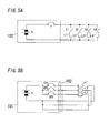
- As shown in
FIG. 5A , there is apower supply device 100, as a conventional power supply device equipped with a protective function for protecting a load from an overcurrent, provided with a fuse F along an output end of a constant-voltage source E with which loads L1-L4 are connected in parallel through switches S1-S4, respectively. - In this
power supply device 100, there is an issue that power feeding to all the loads L1-L4 is shut off when the fuse F is melted by an overcurrent, because the loads L1-L4 are protected from an overcurrent with the fuse F connected along the output end of the constant-voltage source E. - Therefore, in order to protect each load of branch circuits from an overcurrent, a conventional
power supply device 101 is provided with amultipoint connector 102 connected with a plurality of load circuits as shown inFIG. 5B (e.g., Patent Documents 1-4). In thispower supply device 101, a direct-current power from a constant-voltage source E is supplied to loads L1-L3 connected to themultipoint connector 102 via built-in circuit protectors CP1-CP3. When an overcurrent flows by occurrence of short-circuit or the like at any of the loads L1-L3, thepower supply device 101 shuts off, through a break operation by a corresponding one of the circuit protectors CP1-CP3, only power feeding to the branch circuit through which the overcurrent flows. Accordingly, power feeding to the remaining load circuits can be continued. -
- Patent Document 1: Patent Application Publication No.
2002-252923 - Patent Document 2: Patent Application Publication No-
2005-295791 - Patent Document 3: Patent Application Publication No.
2007-252081 - Patent Document 4: Patent Application Publication No.
2008-259254 - In the aforementioned
power supply device 101, there is a problem of low expandability or elasticity because the predetermined number of circuit protectors CP1-CP3 are previously built in, and therefore the number of the branch circuits is fixed and the number of circuits can not be easily changed. - The present invention is provided in view of the aforementioned problems, and an object is to provide a DC branch circuit protecting device, which has high expandability or elasticity and is capable of easily increasing and decreasing the number of circuits.
- In order to achieve the above object, a DC branch circuit protecting device of the present invention comprises a circuit breaker which is, as an internal device, put in a distribution board for distributing direct-current power supply to branch lines and is provided along each of branch lines branched from main wires of the direct-current power supply. The circuit breaker comprises power connecting terminals connected to the main wires in the distribution board, load connecting terminals connected with wires from a load, and a semiconductor switch device provided along an electrical circuit between the power connecting terminals and the load connecting terminals. The circuit breaker also comprises a current sensing means for detecting an electric current through the electrical circuit, and a current setting means to which a set current according to a load connected to the load connecting terminals is set. The circuit breaker further comprises a switch controlling means for coercively turning the semiconductor switch device off when a detection value of the current sensing means exceeds the set current which is set to the current setting means, and an on/off switch that is provided along the electrical circuit and is turned on or off in accordance with a switching operation through a manual operation portion.
- In the DC branch circuit protecting device, it is preferred that: the power connecting terminals comprise plug-in terminals which conductive bars forming the main wires in the distribution board are inserted into and connected with; and the load connecting terminals comprise terminals having quick connection construction, which cores of the wires of which jackets are removed are inserted into and connected with.
- In the DC branch circuit protecting device, it is preferred that a controller for controlling a switching of the circuit breaker is, as an internal device, put in the distribution board along with the circuit breaker, and the switch controlling means is configured to turn the semiconductor switch device on or off in accordance with an on/off control signal from the controller.
- In the DC branch circuit protecting device, it is preferred that the circuit breaker comprises a plurality of circuit breakers, and the controller is provided with a storing means and a control signal outputting means. A sequence for turning the circuit breakers on or off in turn is stored in the storing means. The control signal outputting means supplies each of the circuit breakers with an on/off control signal so that the circuit breakers are turned on or off in turn in accordance with the sequence stored in the storing means.
- In the DC branch circuit protecting device, it is preferred that said circuit breaker is provided with a supervisory signal outputting means configured to supply the controller with a detection value of the current sensing means as a supervisory signal.
- According to the present invention, since the circuit breaker is, as an internal device, put in the distribution board, the necessary number of circuit breakers are provided and thereby the number of branch circuits can be easily increased or decreased. Moreover, in the circuits breaker, since a semiconductor switch device is coercively turned off when the an electric current exceeding a set current according to a load flows, loads can be protected per branch circuit. In addition, a maintenance work can be performed safely by handling the manual operation portion to coercively turn the on/off switch off when the maintenance work is performed at the branch circuit side or the like, because the on/off switch is opened or closed in accordance with a switching operation through the manual operation portion,
-
-
FIG. 1 is a block diagram of a DC branch circuit protecting device in an embodiment, -
FIG. 2 is a perspective view of ditto appearance, -
FIGS. 3A, 3B and 3C are explanatory diagrams showing abnormal-current breaking characteristics, -
FIG. 4 is a system configuration diagram of an AC/DC hybrid wiring system with ditto, and -
FIGS. 5A and 5B are circuit diagrams of prior art power supply devices. - Embodiments of the present invention are now explained with reference with the figures.
- In recent years, diminishing emission of greenhouse gases is required as a global warming countermeasure. Also in civilian sectors, reducing power consumption is promoted in order to reduce carbon-dioxide emissions of energetic origins.
- In ordinary houses, various home electric appliances are used, and many home electric appliances are driven by an alternating-current power supply at present. Accordingly, home electric appliances in each ordinary house are operated by supplying each house with an alternating-current power from an electric power company. On the other hand, there are increasing devices in home electric appliances, which are, for example, air conditioners, refrigerators, washing machines and the like, and each employ inverter control systems. In inverter control type of electric appliances, alternating-current power from an indoor outlet is converted into direct-current power through a built-in AC/DC converter, and then inverted into alternating-current through an inverter circuit, thereby activating a load. Thus, since two conversions from alternating-current to direct-current and from direct-current to alternating-current are performed, power loss is increased by the power conversions.
- Therefore, the present applicant suggests providing housing with an AC/DC hybrid wiring system provided with a direct-current wiring system for supplying direct-current power supply in addition to a conventional alternate-current wiring system for supplying commercial alternating-current power supply.
-
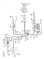
FIG. 4 shows a system configuration of an AC/DC hybrid wiring system. The system shown in the figure is provided with two direct-current wiring systems in addition to an alternate-current wiring system. Direct-current wiring system type ofDC distribution boards current distribution board 30 are installed in housing. The two direct-current wiring systems comprises a low-voltage DC wiring system and a high-voltage DC wiring system. In the low-voltage DC wiring system, a safety extra-low voltage (SELV) such as, for example, DC12V, DC24, DC 48V is supplied. In the high-voltage DC wiring system, a direct-current voltage higher than the SELV power supply (e.g., DC+/- 150V, and DC300V across both ends) is supplied to a direct-current load(s). - In the high-voltage DC wiring system type of
DC distribution board 1A, internal devices such as amain breaker 2, an earthleakage circuit breaker 3 andbranch circuit breakers 4 are put in a main body. Themain breaker 2 is connected with three direct-current power lines 11 (DC150V line, DC -150V line and GND line) pulled in the main body from a direct-current power supply. Load terminals of themain breaker 2 are connected with, through the earthleakage circuit breaker 3, threeconductive bars 12 placed in the main body. A 150V branch circuit breaker(s) 4 is connected between aconductive bar 12 of DC150V or DC(-150V) and the conductive bar of GND. A 300V branch circuit breaker(s) 4 is connected between theconductive bar 12 of DC150V and theconductive bar 12 of DC(-150V). High-voltage direct-current power is supplied to the indoor high-voltage DC wiring 13 which is wired through thebranch circuit breakers 4. The high-voltage DC wiring 13 is wired from theDC distribution board 1A to each room in housing, andDC outlets 80 are located in place. In a direct-current appliance such as an air-conditioning equipment 81, arefrigerator 82 or anelectromagnetic cooker 83 connected to aDC outlet 80, a direct-current voltage from theDC outlet 80 is inverted into a high frequency alternating-current voltage through a built-in inverter circuit, thereby activating the load. - The direct-current power line 11 is connected with an AC/
DC converter 21 and a DC/DC converter 22. Theconverter 21 converts an alternating-current power from the alternating-current distribution board 30 into direct-current, and theconverter 22 converts a voltage value of a direct-current voltage from a dispersedpower supply 40 such as aphotovoltaic facility 41. The direct-current power line 11 is also connected with a discharge andcharge control device 23 for controlling discharge and charge of apower storage facility 42 with, for example, a lithium-ion battery or an electric double layer capacitor. Thepower storage facility 42 is used for: storing an electric power obtained by converting and charging alternating-current into direct-current at midnight during low electric power charge of a commercial alternating-current power supply, and then consuming the power at daytime during high electric power charge; or charging a surplus of an electric power generated by thephotovoltaic facility 41, and then consuming the power as needed by load leveling or the like. In the figure, 24 and 25 are switches for disconnecting the dispersedpower supply 40 and thepower storage facility 42 from a direct-current power system, and 26 is a protector for system protection. - In the low-voltage DC wiring system type of
DC distribution board 1B, internal devices such as circuit breakers 5 (branch circuit breakers) are put in the board. A direct-current power line 15 from a DC/DC converter 16 is pulled in theDC distribution board 1B, andcircuit breakers 5 are connected toconductive bars 17 placed in the main body. The DC/DC converter 16 converts a high direct-current voltage from theDC distribution board 1A into SELV, and SELV is supplied to theconductive bars 17 in theDC distribution board 1B through the direct-current power line 15. An indoor low-voltage DC wiring 18 is wired via acircuit breaker 5, and is connected with anLED fixture 85 such as a downlight through, for example, awall switch 84 to be activated by SELV The low-voltage DC wiring 18 is connected with a direct-current appliance activated by SELV, such as a telephone, a personal computer, a flat-screen TV, an HDD recorder, a ventilating fan in a 24-hour ventilation system or a foot lamp. An internal device put in theDC distribution board 1B may be a device using SELV of, for example, an information device such as an information circuit breaker 7 or aswitching HUB 8, or aDC outlet 9 for supplying SELV power supply. The information circuit breaker 7 is a device equipped with a function for preventing fraudulent access from an external network to an indoor LAN to which indoor equipment items are connected. - In the alternating-
current distribution board 30, a main breaker31 is connected with a single-phase three-wire commercial AC power supply type ofpower line 33 pulled in the main body 30a. Load terminals of themain breaker 31 are connected withconductive bars 34 corresponding to L1 phase, L2 phase and N phase, respectively. A 100V branch circuit breaker(s) 32 is connected between the conductive bar of N phase and the conductive bar of L1 phase or between the conductive bar of N phase and the conductive bar of L2 phase. A 200V branch circuit breaker(s) is connected between the conductive bar of L1 phase and the conductive bar of L2 phase. Indoor alternate-current branch wirings 35 include 100V wiring from which AC100V alternating-current power supply is supplied via a 100Vbranch circuit breaker 32, and 200V wiring from which AC200V alternating-current power supply is supplied via a 200V branch circuit breaker 32- The 100V wiring is connected with alternating-current appliances activated by 100V, such as a light fixture, a cleaner and a wash machine. The 200V wiring is connected with alternating-current appliances activated by 200V, such as an air-conditioning equipment, a refrigerator and anelectromagnetic cooker 83. - A DC branch circuit protecting device in accordance with the present invention is comprised of a circuit breaker(s) 5 and a
controller 6 as internal devices put in the low-voltageDC distribution board 1B. - As shown in
FIG. 2 , anenclosure 50 of acircuit breaker 5 has the same dimensions as one-pole distribution board device. Plug-ingrooves 50a are provided at one end side in a longitudinal direction of theenclosure 50 and connected withconductive bars 17 inserted therein. A power connecting terminal (not shown) formed of a blade spring retainer is located in each plug-ingroove 50a.Wire insertion openings 50b into which wires from a load side are inserted are provided at the other end side in the longitudinal direction of theenclosure 50, and load connecting terminals (not shown) each having quick connection terminal construction are put therein so that they face thewire insertion openings 50b. Therefore, when the core of a wire of which jacket is removed is inserted into awire insertion opening 50b, the wire is connected to the load connecting terminal located therein to be prevented extraction of the wire. A manual operation handle 51 for turning on and off an built-in on/offswitch 52 to be described by manual operation andindicators 59 such as, e.g., LEDs for representing an operating condition by lighting condition are also placed at the front face of theenclosure 50. A conventional well-known terminal as disclosed in, for example, Patent Application Publication No.2004-234921 is employed as each terminal having quick connection construction, which is not described in detail herein. - A circuit configuration of the
circuit breaker 5 is now explained with reference toFIG. 1 . Thecircuit breaker 5 includes power connecting terminals t1, t2 connected with theconductive bars 17 inserted therein and load connecting terminals t3, t4 connected with wires from a load. A double pole single throw type of on/offswitch 52 is connected along an electrically-conducting path between the terminals t1-t3 and an electrically-conducting path between the terminals t2-t4. This on/offswitch 52 is switched on or off in accordance with a switching operation through the manual operation handle 51. Asemiconductor switch device 53 such as MOSFET, acurrent sensing resistor 54, athermal fuse 55, acurrent sensing resistor 56 and asemiconductor switch device 57 such as MOSFET are connected in series between the load connecting terminal t3 at a positive side and the on/offswitch 52. Thecircuit breaker 5 includes an I/F circuit 62 for inputting and outputting a signal with respect to thecontroller 6. When a switch control signal from thecontroller 6 is input to anarithmetic circuit 60 via the I/F circuit 62, thearithmetic circuit 60 as a switching controlling means turns thesemiconductor switch device 57 on or off in accordance with control information of the switch control signal. Thearithmetic circuit 60 also represents an operation condition by changing the lighting condition (lighting, extinction or blinking) of theindicators 59 such as LEDs. Apower supply circuit 61 for generating operating power supply of thearithmetic circuit 60 obtains power supply from the upstream of the on/offswitch 52, and can activate thearithmetic circuit 60 even when the on/offswitch 52 is turned off. - The
semiconductor switch device 53 is adapted to be turned off when voltage depression across thecurrent sensing resistor 54 exceeds a predetermined reference value, thereby limiting an electric current flowing through the electrical circuit to a predetermined reference value (e.g., 15A). - When detecting an abnormal current flow such as an overload current or a short-circuit current based on voltage depression across the
current sensing resistor 56 as a current sensing means, thearithmetic circuit 60 turns thesemiconductor switch device 57 off in accordance with a predetermined breaking characteristic. The breaking characteristic of thearithmetic circuit 60 can be set to a characteristic of instantaneous detection, standard detection, longtime detection, Mag-Only or the like. -
FIG. 3A shows an instantaneous detection type of breaking characteristic. When an electric current of x(A) or more flows continuously for 20ms, thearithmetic circuit 60 turns thesemiconductor switch device 57 off.FIG. 3B shows a standard detection type of breaking characteristic- In this case, thearithmetic circuit 60 turns thesemiconductor switch device 57 off when an electric current of x(A) or more and less than 10A flows continuously for 100ms, or when an electric current of 10A or more and less than 13A flows continuously for 60ms, or when an electric current of 13A or more flows continuously for 20ms.FIG. 3C shows a longtime detection type of breaking characteristic. In this case, thearithmetic circuit 60 turns thesemiconductor switch device 57 off when an electric current of x(A) or more and less than 10A flows continuously for 1000ms, or when an electric current of 10A or more and less than 13A flows continuously for 800ms, or when an electric current of 13A or more flows continuously for 20ms. In any of the breaking characteristics, when an electric current of 15A or more flows, the electrical circuit is cut off by thesemiconductor switch device 53.FIGS. 3A-3C show examples of the breaking characteristics, but in thearithmetic circuit 60, a current limit value (a setting current) and a breaking time with respect to the setting current may be set and changed appropriately based on load characteristics. - The
arithmetic circuit 60 also includes a function for preventing an abnormal voltage from being supplied to a load circuit by turning thesemiconductor switch device 57 off when avoltage detecting circuit 58 detects an abnormal input voltage (an excess voltage or an undervoltage). - The
controller 6 has a function for controlling a switching condition of a plurality ofcircuit breakers 5, and includes acontrol circuit 63, a storage device 64 (a storing means), adisplay 65 and an I/F circuit 66. Thestorage device 64 comprises a nonvolatile memory, and stores sequences for turning thecircuit breakers 5 on or off in turn. Thedisplay 65 is, for example, a liquid crystal display (LCD). The I/F circuit 66 is configured to input and output a signal with respect to thecircuit breakers 5. - The
controller 6 also includes different functions such as a branch output stopping function, a sequential turn-on function, a sequential turn-off function, an outage detecting function, a total voltage depression detecting function and a total current detecting function. During execution of the branch output stopping function, thecontrol circuit 63 supplies an off control signal to a desiredcircuit breaker 5 via the I/F circuit 66, thereby turning thecircuit breaker 5 off. During execution of the sequential turn-on function, thecontrol circuit 63 as a control signal outputting means supplies an on control signal to thecircuit breakers 5 in turn via the I/F circuit 66 in accordance with a sequence read from thestorage device 64, thereby turning thecircuit breakers 5 on in predetermined order. During execution of the sequential turn-off function, thecontrol circuit 63 as the control signal outputting means supplies an off control signal to thecircuit breakers 5 in turn via the I/F circuit 66 in accordance with a sequence read from thestorage device 64, thereby turning thecircuit breakers 5 off in predetermined order. During execution of the outage detecting function, thecontrol circuit 63 detects the existence or nonexistence of outage based on a detection result of a voltage detecting means (not shown) for detecting a line voltage of a direct-current power line 15, and also announces outage occurrence through thedisplay 65 when outage is detected. Power supply of thecontroller 6 is backed up by a secondary battery (not shown) so that it can continue the operation till the end of a protection time from outage occurrence. In the total current detecting function, thecontrol circuit 63 calculates a sum of electric currents flowing through thecircuit breakers 5 based on each current value from thecircuit breakers 5 via the I/F circuit 66. When the sum of electric currents exceeds a preset value, thecontrol circuit 63 supplies an off control signal to eachcircuit breaker 5 via the I/F circuit 66 to turn eachcircuit breaker 5 off. - As presented above, the DC branch circuit protecting device in the embodiment is, as an internal device, put in the
DC distribution board 1B for distributing direct-current power supply to branch lines, and includescircuit breakers 5 each provided along branch lines branched from main wires of a direct-current power supply. Thecircuit breaker 5 includes power connecting terminals t1, t2 connected to the main wires in theDC distribution board 1B, and load connecting terminals t3, t4 connected to wires of a load side. Thecircuit breaker 5 also includes asemiconductor switch device 53 provided along an electrical circuit between the power connecting terminal t1 and the load connecting terminal t3, and acurrent sensing resistor 56 for detecting an electric current through the electrical circuit. Thecircuit breaker 5 also includes the arithmetic circuit 60 (a current setting means, a switch controlling means) which a set current according to a load connected to the load connecting terminals t3, t4 is set to, and which is configured to coercively turn thesemiconductor switch device 53 off when a detection value of the current sensing means exceeds the set current. Thecircuit breaker 5 further includes the on/offswitch 52 which is provided along the electrical circuit and opens or closes in accordance with an switching operation through a manual operation portion (the manual operation portion). - Thus, since the
circuit breaker 5 is, as an internal device, put in theDC distribution board 1B, the necessary number ofcircuit breakers 5 are provided and thereby branch circuits can be easily increased or decreased. Moreover, in thecircuits breaker 5, since asemiconductor switch device 53 is coercively turned off when the an electric current exceeding a set current according to a load flows, loads can be protected per branch circuit. In addition, since an on/offswitch 52 is opened or closed in accordance with a switching operation through the manual operation portion, a maintenance work can be performed safely by handling the manual operation handle 51 to coercively turn the on/offswitch 52 off when the maintenance work is performed at the branch circuit side or the like. - Moreover, in the
circuit breaker 5, since thesemiconductor switch device 57 is turned on or off in accordance with an on/off control signal from thecontroller 6, power feeding to the branch circuit can turned on/off through thecontroller 6. - A load can be also protected by coercively turning the
semiconductor switch device 57 off when an electric current exceeding the set current flows. - The
controller 6 for controlling switching of thecircuit breakers 5 sequentially turns thecircuit breakers 5 on or off in accordance with a sequence stored in thestorage device 64. - Thus, branch circuits connected to the circuit breakers are sequentially turned on or off in accordance with a sequence stored in the storing means, and thereby allowing power supply to loads connected to the branch circuits to start in predetermined order or allowing the power supply to stop.
- Each
circuit breaker 5 also includes: plug-in terminals such as blade spring retainers whichconductive bars 17 as power connecting terminals are inserted into and connected to; and terminals each having quick connection construction as load connecting terminals to be connected with inserted cores of wires of which jackets are removed. - Thereby, it is easy to perform a work for connecting the power connecting terminals of a
circuit breaker 5 toconductive bars 17. Since a work for screw tightening is unnecessary, it is easy to perform a work for connecting load connecting terminals and wires from a load, and to perform an electrically connecting work of acircuit breaker 5. - In each
circuit breaker 5, anarithmetic circuit 60 as a supervisory signal outputting means calculates a current value from a voltage depression across thecurrent sensing resistor 56 to supply the current value as a supervisory signal to thecontroller 6 through the I/F circuit 62. - Thereby, the controller can obtain each current value though the branch circuits.
- In each
circuit breaker 5, an on/offswitch 52 is turned on or off in accordance with a switching operation through the manual operation handle 51. It is therefore possible to perform a maintenance work safely by handling the manual operation handle 51 to coercively turn the on/offswitch 52 off when the maintenance work is performed at the branch circuit side or the like. - In the embodiment, the
circuit breaker 5 supplies the branch circuit with a direct-current voltage obtained through theconductive bars 17 without change, but thecircuit breaker 5 may include a built-in DC/DC converter (not shown) and be configured to supply a direct-current voltage of which voltage value is changed through the DC/DC converter. - As presented above, according to the DC branch circuit protecting device of the present invention, a circuit breaker is, as an internal device, put in a distribution board, and it is accordingly possible to easily increase or decrease the number of branch circuits by installing the necessary number of circuit breakers. Moreover, loads can be protected per branch circuit because each semiconductor switch device is coercively turned off when an electric current exceeding a set current according to a load flows. In addition, an on/off switch is opened or closed in accordance with a switching operation through the manual operation portion, and accordingly a maintenance work can be performed safely by handling the manual operation portion to coercively turn the on/off switch off when the maintenance work is performed at the branch circuit side.
-
- 1B DC distribution board
- 5 circuit breaker
- 6 controller
- 15 direct-current power line (main wires)
- 16 DC/DC converter (direct-current power supply)
- 17 conductive bar (main wire)
- 56 current sensing resistor (current sensing means)
- 57 semiconductor switch device
- 60 arithmetic circuit (switch controlling means)
- t1, t2 power connecting terminal
- t3, t4 load connecting terminal
Claims (5)
- A DC branch circuit protecting device, comprising a circuit breaker which is, as an internal device, put in a distribution board for distributing a direct-current power supply to branch lines and is provided along each of branch lines branched from main wires of the direct-current power supply,
wherein the circuit breaker comprises:power connecting terminals connected to the main wires in the distribution board;load connecting terminals connected with wires from a load;a semiconductor switch device provided along an electrical circuit between the power connecting terminals and the load connecting terminals;a current sensing means for detecting an electric current through the electrical circuit;a current setting means which a set current according to a load connected to the load connecting terminals is set to;a switch controlling means for coercively turning the semiconductor switch device off when a detection value of the current sensing means exceeds the set current set to the current setting means; andan on/off switch that is provided along the electrical circuit and is turned on or off in accordance with a switching operation through a manual operation portion. - The DC branch circuit protecting device of claim 1,
wherein the power connecting terminals comprise plug-in terminals which conductive bars forming the main wires in the distribution board are inserted into and connected with, and
wherein the load connecting terminals comprise terminals each having quick connection construction, which cores of the wires of which jackets are removed are inserted into and connected with. - The DC branch circuit protecting device of claim 1 or 2,
wherein a controller for controlling a switching of the circuit breaker is, as an internal device, put in the distribution board along with the circuit breaker, and
wherein the switch controlling means is configured to turn the semiconductor switch device on or off in accordance with an on/off control signal from the controller. - The DC branch circuit protecting device of claim 3,
wherein the circuit breaker comprises a plurality of circuit breakers, and
wherein the controller is provided with: a storing means for storing a sequence for turning the circuit breakers on or off in turn; and a control signal outputting means configured to supply each of the circuit breakers with an on/off control signal so that the circuit breakers are turned on or off in turn in accordance with the sequence stored in the storing means. - The DC branch circuit protecting device of claim 3 or 4, wherein said circuit breaker is provided with a supervisory signal outputting means configured to supply the controller with a detection value of the current sensing means as a supervisory signal.
Applications Claiming Priority (2)
| Application Number | Priority Date | Filing Date | Title |
|---|---|---|---|
| JP2009148962A JP2011010393A (en) | 2009-06-23 | 2009-06-23 | Apparatus for protecting direct current branch circuit |
| PCT/JP2010/060362 WO2010150706A1 (en) | 2009-06-23 | 2010-06-18 | Apparatus for protecting direct current branch circuit |
Publications (3)
| Publication Number | Publication Date |
|---|---|
| EP2448075A1 true EP2448075A1 (en) | 2012-05-02 |
| EP2448075A4 EP2448075A4 (en) | 2014-04-23 |
| EP2448075B1 EP2448075B1 (en) | 2015-12-02 |
Family
ID=43386475
Family Applications (1)
| Application Number | Title | Priority Date | Filing Date |
|---|---|---|---|
| EP10792024.1A Not-in-force EP2448075B1 (en) | 2009-06-23 | 2010-06-18 | Apparatus for protecting direct current branch circuit |
Country Status (5)
| Country | Link |
|---|---|
| US (1) | US8929046B2 (en) |
| EP (1) | EP2448075B1 (en) |
| JP (1) | JP2011010393A (en) |
| CN (1) | CN102804528B (en) |
| WO (1) | WO2010150706A1 (en) |
Cited By (4)
| Publication number | Priority date | Publication date | Assignee | Title |
|---|---|---|---|---|
| EP2783441A4 (en) * | 2011-11-25 | 2015-08-12 | Shenzhen Byd Auto R & D Co Ltd | POWER BATTERY ASSEMBLY AND ELECTRIC VEHICLE COMPRISING THE SAME |
| EP3166192A4 (en) * | 2014-07-02 | 2017-07-12 | Panasonic Intellectual Property Management Co., Ltd. | Leakage protection device and leakage protection system |
| WO2023052042A1 (en) * | 2021-09-28 | 2023-04-06 | Siemens Aktiengesellschaft | Circuit breaker |
| WO2023052146A1 (en) * | 2021-09-28 | 2023-04-06 | Siemens Aktiengesellschaft | Circuit breaker and method |
Families Citing this family (29)
| Publication number | Priority date | Publication date | Assignee | Title |
|---|---|---|---|---|
| EP2684204B1 (en) * | 2011-03-11 | 2015-04-01 | Siemens Aktiengesellschaft | Circuit breaker system for guidesystem for the electrical supply of a vehicle |
| CN102270841B (en) * | 2011-07-19 | 2014-10-22 | 中电普瑞科技有限公司 | Positioning system for direct current magnetic bias suppression device |
| JP5858236B2 (en) * | 2012-06-01 | 2016-02-10 | 東芝ライテック株式会社 | Battery system |
| JP5778706B2 (en) * | 2013-02-20 | 2015-09-16 | 不二電機工業株式会社 | Semiconductor switch |
| JP2015165729A (en) * | 2014-02-28 | 2015-09-17 | 株式会社Nttファシリティーズ | Power supply system, power supply control device, power supply control method and program in power supply system |
| US20150349514A1 (en) * | 2014-05-27 | 2015-12-03 | Zonesking Technology Co., Ltd. | Multifunctional electrical power output protection device |
| DE102014108657A1 (en) * | 2014-06-20 | 2015-12-24 | Eaton Industries Austria Gmbh | Protection device |
| KR102442187B1 (en) * | 2015-04-10 | 2022-09-07 | 삼성에스디아이 주식회사 | battery protection circuit |
| US10598703B2 (en) | 2015-07-20 | 2020-03-24 | Eaton Intelligent Power Limited | Electric fuse current sensing systems and monitoring methods |
| CN105356431A (en) * | 2015-12-04 | 2016-02-24 | 浪潮电子信息产业股份有限公司 | A device for preventing the power failure of the whole cabinet caused by the failure of the secondary power board parts |
| JP2017114373A (en) * | 2015-12-25 | 2017-06-29 | 矢崎総業株式会社 | Junction box |
| JP2017130285A (en) * | 2016-01-18 | 2017-07-27 | 株式会社オートネットワーク技術研究所 | Circuit board and power supply control device |
| JP6284683B1 (en) * | 2016-04-06 | 2018-03-07 | 新電元工業株式会社 | Power module |
| CN106328457A (en) * | 2016-08-29 | 2017-01-11 | 苏州未来电器股份有限公司 | Overload protection device for circuit breaker and control method thereof |
| DE102016123860A1 (en) * | 2016-12-08 | 2018-06-14 | Phoenix Contact Gmbh & Co. Kg | Protection arrangement of electrical loads and their connection lines against overcurrent |
| LU93345B1 (en) | 2016-12-08 | 2018-06-08 | Phoenix Contact Gmbh & Co Kg Intellectual Property Licenses & Standards | Protection arrangement of electrical loads and their connection lines against overcurrent |
| DE102017202208A1 (en) * | 2017-02-13 | 2018-08-16 | Siemens Aktiengesellschaft | Supply device for an electrical module with securing element |
| WO2018236710A1 (en) * | 2017-06-21 | 2018-12-27 | Nextek Power Systems, Inc. | SAFETY PROTECTION FOR CLASS 2 ELECTRIC CIRCUITS |
| US10629391B2 (en) | 2017-12-21 | 2020-04-21 | Eaton Intelligent Power Limited | Fusible safety disconnect in solid state circuit breakers and combination motor starters |
| KR102185036B1 (en) | 2018-04-30 | 2020-12-01 | 엘에스일렉트릭(주) | Circuit breaker control module |
| US11143718B2 (en) | 2018-05-31 | 2021-10-12 | Eaton Intelligent Power Limited | Monitoring systems and methods for estimating thermal-mechanical fatigue in an electrical fuse |
| US11289298B2 (en) | 2018-05-31 | 2022-03-29 | Eaton Intelligent Power Limited | Monitoring systems and methods for estimating thermal-mechanical fatigue in an electrical fuse |
| US10965132B2 (en) * | 2018-09-14 | 2021-03-30 | General Electric Company | Grounding circuit for a backup power source |
| CN112771745B (en) * | 2018-10-01 | 2023-08-25 | 三菱电机株式会社 | DC power distribution system |
| CN110661236B (en) * | 2019-01-07 | 2022-01-25 | 台达电子企业管理(上海)有限公司 | Circuit breaker apparatus and system |
| US11127552B2 (en) * | 2019-04-05 | 2021-09-21 | Eaton Intelligent Power Limited | Hybrid switch assembly and circuit interrupter including the same |
| US12015266B2 (en) | 2019-07-11 | 2024-06-18 | Mitsubishi Electric Corporation | DC distribution panel |
| CN114162744B (en) * | 2021-11-05 | 2024-08-13 | 恒宏智能装备有限公司 | An electric jack with a current limiting protector |
| WO2025203618A1 (en) * | 2024-03-29 | 2025-10-02 | 三菱電機株式会社 | Semiconductor circuit breaker and board using semiconductor circuit breaker |
Family Cites Families (24)
| Publication number | Priority date | Publication date | Assignee | Title |
|---|---|---|---|---|
| JPS6276117A (en) | 1985-09-27 | 1987-04-08 | 富士電機株式会社 | Tripping device for circuit breaker |
| FR2651915B1 (en) | 1989-09-13 | 1991-11-08 | Merlin Gerin | ULTRA-FAST STATIC CIRCUIT BREAKER WITH GALVANIC ISOLATION. |
| US5463252A (en) * | 1993-10-01 | 1995-10-31 | Westinghouse Electric Corp. | Modular solid state relay |
| JP3804176B2 (en) | 1997-04-28 | 2006-08-02 | 松下電工株式会社 | Hybrid type DC switch |
| JP2000215780A (en) | 1999-01-26 | 2000-08-04 | Matsushita Electric Works Ltd | Terminal device for circuit breaker |
| JP2000236621A (en) * | 1999-02-14 | 2000-08-29 | Yazaki Corp | Power supply control circuit |
| US20020080544A1 (en) * | 2000-12-22 | 2002-06-27 | John Pellegrino | Apparatus and methods for limiting electrical current in circuit breaker applications |
| JP3899827B2 (en) | 2001-02-26 | 2007-03-28 | オムロン株式会社 | Output branch device and shut-off unit |
| US6870720B2 (en) | 2002-01-25 | 2005-03-22 | Pacific Engineering Corp. | Device and method for determining intermittent short circuit |
| US6952335B2 (en) | 2002-03-22 | 2005-10-04 | Virginia Tech Intellectual Properties, Inc. | Solid-state DC circuit breaker |
| ES2308005T3 (en) * | 2002-10-24 | 2008-12-01 | HI-TECH ELECTRONIC PRODUCTS & MFG., INC. | APPARATUS AND METHOD TO SIMULTANEOUSLY DETECT THE STATE OF ENERGY OF A PLURALITY OF SWITCHING SWITCHES. |
| JP3809649B2 (en) | 2002-12-04 | 2006-08-16 | デンセイ・ラムダ株式会社 | Distribution board system |
| JP2004234921A (en) | 2003-01-28 | 2004-08-19 | Matsushita Electric Works Ltd | Circuit breaker |
| JP4453955B2 (en) * | 2003-03-12 | 2010-04-21 | 日東工業株式会社 | Distribution board |
| US20050116814A1 (en) * | 2003-10-24 | 2005-06-02 | Rodgers Barry N. | Intelligent power management control system |
| JP2005295791A (en) | 2004-03-08 | 2005-10-20 | Omron Corp | Terminal block unit and control method thereof |
| CN2796199Y (en) * | 2004-12-15 | 2006-07-12 | 辽宁省电力有限公司辽阳供电公司 | Unattended online monitoring comprehensive automatic control cabinet |
| JP4720559B2 (en) | 2006-03-15 | 2011-07-13 | オムロン株式会社 | Circuit protection device and short-circuit current interruption method thereof |
| JP5199555B2 (en) | 2006-08-02 | 2013-05-15 | パナソニック株式会社 | Power distribution system |
| JP5049040B2 (en) | 2007-03-30 | 2012-10-17 | パナソニック株式会社 | DC power distribution system |
| JP2009178027A (en) | 2007-12-25 | 2009-08-06 | Panasonic Electric Works Co Ltd | DC power distribution system |
| JP5108670B2 (en) | 2008-07-31 | 2012-12-26 | パナソニック株式会社 | DC switch |
| US8068322B2 (en) * | 2008-07-31 | 2011-11-29 | Honeywell International Inc. | Electronic circuit breaker apparatus and systems |
| WO2010013783A1 (en) * | 2008-08-01 | 2010-02-04 | パナソニック電工株式会社 | Power distribution system |
-
2009
- 2009-06-23 JP JP2009148962A patent/JP2011010393A/en not_active Withdrawn
-
2010
- 2010-06-18 US US13/380,183 patent/US8929046B2/en not_active Expired - Fee Related
- 2010-06-18 WO PCT/JP2010/060362 patent/WO2010150706A1/en not_active Ceased
- 2010-06-18 EP EP10792024.1A patent/EP2448075B1/en not_active Not-in-force
- 2010-06-18 CN CN201080027729.8A patent/CN102804528B/en not_active Expired - Fee Related
Cited By (7)
| Publication number | Priority date | Publication date | Assignee | Title |
|---|---|---|---|---|
| EP2783441A4 (en) * | 2011-11-25 | 2015-08-12 | Shenzhen Byd Auto R & D Co Ltd | POWER BATTERY ASSEMBLY AND ELECTRIC VEHICLE COMPRISING THE SAME |
| US9293910B2 (en) | 2011-11-25 | 2016-03-22 | Shenzhen Byd Auto R&D Company Limited | Power battery assembly and electric vehicle comprising the same |
| EP3166192A4 (en) * | 2014-07-02 | 2017-07-12 | Panasonic Intellectual Property Management Co., Ltd. | Leakage protection device and leakage protection system |
| AU2015285887B2 (en) * | 2014-07-02 | 2018-07-05 | Panasonic Intellectual Property Management Co., Ltd. | Residual current protection device and residual current protection system |
| WO2023052042A1 (en) * | 2021-09-28 | 2023-04-06 | Siemens Aktiengesellschaft | Circuit breaker |
| WO2023052146A1 (en) * | 2021-09-28 | 2023-04-06 | Siemens Aktiengesellschaft | Circuit breaker and method |
| US12562322B2 (en) | 2021-09-28 | 2026-02-24 | Siemens Aktiengesellschaft | Circuit breaker |
Also Published As
| Publication number | Publication date |
|---|---|
| WO2010150706A1 (en) | 2010-12-29 |
| JP2011010393A (en) | 2011-01-13 |
| EP2448075B1 (en) | 2015-12-02 |
| CN102804528B (en) | 2016-02-17 |
| EP2448075A4 (en) | 2014-04-23 |
| CN102804528A (en) | 2012-11-28 |
| US8929046B2 (en) | 2015-01-06 |
| US20120099236A1 (en) | 2012-04-26 |
Similar Documents
| Publication | Publication Date | Title |
|---|---|---|
| US8929046B2 (en) | DC branch circuit protecting device | |
| US8279574B2 (en) | Emergency lighting system | |
| WO2011068322A3 (en) | Fire-preventing and power-saving intelligent multi-outlet | |
| EP2980952A1 (en) | Power supply control device | |
| CA2629871A1 (en) | Overload alarm device and method thereof | |
| JP2010041759A (en) | Power distribution system | |
| JP5565932B2 (en) | Power distribution system | |
| KR100709005B1 (en) | Emergency power automatic switching device | |
| CN214125542U (en) | Low-voltage heater control circuit | |
| JP7505924B2 (en) | Building power supply switching system | |
| KR20050055183A (en) | Automatic power switching device | |
| CN203826804U (en) | Illumination power distribution box | |
| JP2001298814A (en) | Power supply | |
| GB2477327A (en) | Domestic voltage reduction device | |
| TWM621576U (en) | Electricity usage detection and distribution device | |
| US10491005B2 (en) | Intelligent current limiting to enable chaining of AC appliances | |
| CN220732355U (en) | Distribution box for internet data center machine room | |
| CN113140941B (en) | Alternating current power supply switching control circuit and alternating current power supply switching cabinet with same | |
| CN212543146U (en) | Digital transformer substation power distribution device | |
| CN104393500A (en) | Time division power supply system of LED display screen | |
| CN1949614A (en) | Power controller | |
| GB2509856A (en) | Voltage control apparatus having selectively reduced voltage | |
| JP2003333750A (en) | Power-saving controller for power distribution facility | |
| EP3056830A1 (en) | Reduced power consumption in air conditioners | |
| KR101374739B1 (en) | Automatic apparatus for controlling line voltage for maximum electric power |
Legal Events
| Date | Code | Title | Description |
|---|---|---|---|
| PUAI | Public reference made under article 153(3) epc to a published international application that has entered the european phase |
Free format text: ORIGINAL CODE: 0009012 |
|
| 17P | Request for examination filed |
Effective date: 20111215 |
|
| AK | Designated contracting states |
Kind code of ref document: A1 Designated state(s): AL AT BE BG CH CY CZ DE DK EE ES FI FR GB GR HR HU IE IS IT LI LT LU LV MC MK MT NL NO PL PT RO SE SI SK SM TR |
|
| RAP1 | Party data changed (applicant data changed or rights of an application transferred) |
Owner name: PANASONIC CORPORATION |
|
| DAX | Request for extension of the european patent (deleted) | ||
| A4 | Supplementary search report drawn up and despatched |
Effective date: 20140321 |
|
| RIC1 | Information provided on ipc code assigned before grant |
Ipc: H02H 7/26 20060101ALN20140317BHEP Ipc: H02J 1/06 20060101ALI20140317BHEP Ipc: H01H 71/12 20060101ALN20140317BHEP Ipc: H02H 3/10 20060101ALN20140317BHEP Ipc: H02B 1/00 20060101ALI20140317BHEP Ipc: H02B 1/40 20060101AFI20140317BHEP Ipc: H02H 3/087 20060101ALI20140317BHEP Ipc: H01H 73/02 20060101ALI20140317BHEP |
|
| 17Q | First examination report despatched |
Effective date: 20141204 |
|
| RAP1 | Party data changed (applicant data changed or rights of an application transferred) |
Owner name: PANASONIC INTELLECTUAL PROPERTY MANAGEMENT CO., LT |
|
| GRAP | Despatch of communication of intention to grant a patent |
Free format text: ORIGINAL CODE: EPIDOSNIGR1 |
|
| RIC1 | Information provided on ipc code assigned before grant |
Ipc: H01H 71/12 20060101ALN20150526BHEP Ipc: H02H 7/26 20060101ALN20150526BHEP Ipc: H01H 73/02 20060101ALI20150526BHEP Ipc: H02B 1/00 20060101ALI20150526BHEP Ipc: H02B 1/40 20060101AFI20150526BHEP Ipc: H02H 3/087 20060101ALI20150526BHEP Ipc: H02H 3/10 20060101ALN20150526BHEP Ipc: H02J 1/06 20060101ALI20150526BHEP |
|
| RIC1 | Information provided on ipc code assigned before grant |
Ipc: H02H 7/26 20060101ALN20150608BHEP Ipc: H01H 73/02 20060101ALI20150608BHEP Ipc: H02B 1/40 20060101AFI20150608BHEP Ipc: H02J 1/06 20060101ALI20150608BHEP Ipc: H02B 1/00 20060101ALI20150608BHEP Ipc: H01H 71/12 20060101ALN20150608BHEP Ipc: H02H 3/087 20060101ALI20150608BHEP Ipc: H02H 3/10 20060101ALN20150608BHEP |
|
| INTG | Intention to grant announced |
Effective date: 20150625 |
|
| GRAS | Grant fee paid |
Free format text: ORIGINAL CODE: EPIDOSNIGR3 |
|
| GRAA | (expected) grant |
Free format text: ORIGINAL CODE: 0009210 |
|
| RIN1 | Information on inventor provided before grant (corrected) |
Inventor name: KOSHIN, HIROAKI Inventor name: CYUZAWA, TAKAAKI |
|
| AK | Designated contracting states |
Kind code of ref document: B1 Designated state(s): AL AT BE BG CH CY CZ DE DK EE ES FI FR GB GR HR HU IE IS IT LI LT LU LV MC MK MT NL NO PL PT RO SE SI SK SM TR |
|
| REG | Reference to a national code |
Ref country code: GB Ref legal event code: FG4D |
|
| REG | Reference to a national code |
Ref country code: AT Ref legal event code: REF Ref document number: 764001 Country of ref document: AT Kind code of ref document: T Effective date: 20151215 Ref country code: CH Ref legal event code: EP |
|
| REG | Reference to a national code |
Ref country code: IE Ref legal event code: FG4D |
|
| REG | Reference to a national code |
Ref country code: DE Ref legal event code: R096 Ref document number: 602010029389 Country of ref document: DE |
|
| REG | Reference to a national code |
Ref country code: NL Ref legal event code: MP Effective date: 20160302 |
|
| REG | Reference to a national code |
Ref country code: LT Ref legal event code: MG4D |
|
| REG | Reference to a national code |
Ref country code: AT Ref legal event code: MK05 Ref document number: 764001 Country of ref document: AT Kind code of ref document: T Effective date: 20151202 |
|
| PG25 | Lapsed in a contracting state [announced via postgrant information from national office to epo] |
Ref country code: NO Free format text: LAPSE BECAUSE OF FAILURE TO SUBMIT A TRANSLATION OF THE DESCRIPTION OR TO PAY THE FEE WITHIN THE PRESCRIBED TIME-LIMIT Effective date: 20160302 Ref country code: ES Free format text: LAPSE BECAUSE OF FAILURE TO SUBMIT A TRANSLATION OF THE DESCRIPTION OR TO PAY THE FEE WITHIN THE PRESCRIBED TIME-LIMIT Effective date: 20151202 Ref country code: LT Free format text: LAPSE BECAUSE OF FAILURE TO SUBMIT A TRANSLATION OF THE DESCRIPTION OR TO PAY THE FEE WITHIN THE PRESCRIBED TIME-LIMIT Effective date: 20151202 |
|
| PG25 | Lapsed in a contracting state [announced via postgrant information from national office to epo] |
Ref country code: LV Free format text: LAPSE BECAUSE OF FAILURE TO SUBMIT A TRANSLATION OF THE DESCRIPTION OR TO PAY THE FEE WITHIN THE PRESCRIBED TIME-LIMIT Effective date: 20151202 Ref country code: FI Free format text: LAPSE BECAUSE OF FAILURE TO SUBMIT A TRANSLATION OF THE DESCRIPTION OR TO PAY THE FEE WITHIN THE PRESCRIBED TIME-LIMIT Effective date: 20151202 Ref country code: SE Free format text: LAPSE BECAUSE OF FAILURE TO SUBMIT A TRANSLATION OF THE DESCRIPTION OR TO PAY THE FEE WITHIN THE PRESCRIBED TIME-LIMIT Effective date: 20151202 Ref country code: AT Free format text: LAPSE BECAUSE OF FAILURE TO SUBMIT A TRANSLATION OF THE DESCRIPTION OR TO PAY THE FEE WITHIN THE PRESCRIBED TIME-LIMIT Effective date: 20151202 Ref country code: NL Free format text: LAPSE BECAUSE OF FAILURE TO SUBMIT A TRANSLATION OF THE DESCRIPTION OR TO PAY THE FEE WITHIN THE PRESCRIBED TIME-LIMIT Effective date: 20151202 Ref country code: GR Free format text: LAPSE BECAUSE OF FAILURE TO SUBMIT A TRANSLATION OF THE DESCRIPTION OR TO PAY THE FEE WITHIN THE PRESCRIBED TIME-LIMIT Effective date: 20160303 Ref country code: PL Free format text: LAPSE BECAUSE OF FAILURE TO SUBMIT A TRANSLATION OF THE DESCRIPTION OR TO PAY THE FEE WITHIN THE PRESCRIBED TIME-LIMIT Effective date: 20151202 |
|
| PG25 | Lapsed in a contracting state [announced via postgrant information from national office to epo] |
Ref country code: IS Free format text: LAPSE BECAUSE OF FAILURE TO SUBMIT A TRANSLATION OF THE DESCRIPTION OR TO PAY THE FEE WITHIN THE PRESCRIBED TIME-LIMIT Effective date: 20151202 |
|
| PG25 | Lapsed in a contracting state [announced via postgrant information from national office to epo] |
Ref country code: CZ Free format text: LAPSE BECAUSE OF FAILURE TO SUBMIT A TRANSLATION OF THE DESCRIPTION OR TO PAY THE FEE WITHIN THE PRESCRIBED TIME-LIMIT Effective date: 20151202 Ref country code: IT Free format text: LAPSE BECAUSE OF FAILURE TO SUBMIT A TRANSLATION OF THE DESCRIPTION OR TO PAY THE FEE WITHIN THE PRESCRIBED TIME-LIMIT Effective date: 20151202 |
|
| PGFP | Annual fee paid to national office [announced via postgrant information from national office to epo] |
Ref country code: DE Payment date: 20160621 Year of fee payment: 7 |
|
| PG25 | Lapsed in a contracting state [announced via postgrant information from national office to epo] |
Ref country code: EE Free format text: LAPSE BECAUSE OF FAILURE TO SUBMIT A TRANSLATION OF THE DESCRIPTION OR TO PAY THE FEE WITHIN THE PRESCRIBED TIME-LIMIT Effective date: 20151202 Ref country code: RO Free format text: LAPSE BECAUSE OF FAILURE TO SUBMIT A TRANSLATION OF THE DESCRIPTION OR TO PAY THE FEE WITHIN THE PRESCRIBED TIME-LIMIT Effective date: 20151202 Ref country code: SM Free format text: LAPSE BECAUSE OF FAILURE TO SUBMIT A TRANSLATION OF THE DESCRIPTION OR TO PAY THE FEE WITHIN THE PRESCRIBED TIME-LIMIT Effective date: 20151202 Ref country code: SK Free format text: LAPSE BECAUSE OF FAILURE TO SUBMIT A TRANSLATION OF THE DESCRIPTION OR TO PAY THE FEE WITHIN THE PRESCRIBED TIME-LIMIT Effective date: 20151202 Ref country code: PT Free format text: LAPSE BECAUSE OF FAILURE TO SUBMIT A TRANSLATION OF THE DESCRIPTION OR TO PAY THE FEE WITHIN THE PRESCRIBED TIME-LIMIT Effective date: 20160404 Ref country code: IS Free format text: LAPSE BECAUSE OF FAILURE TO SUBMIT A TRANSLATION OF THE DESCRIPTION OR TO PAY THE FEE WITHIN THE PRESCRIBED TIME-LIMIT Effective date: 20160402 |
|
| REG | Reference to a national code |
Ref country code: DE Ref legal event code: R097 Ref document number: 602010029389 Country of ref document: DE |
|
| PLBE | No opposition filed within time limit |
Free format text: ORIGINAL CODE: 0009261 |
|
| STAA | Information on the status of an ep patent application or granted ep patent |
Free format text: STATUS: NO OPPOSITION FILED WITHIN TIME LIMIT |
|
| PG25 | Lapsed in a contracting state [announced via postgrant information from national office to epo] |
Ref country code: DK Free format text: LAPSE BECAUSE OF FAILURE TO SUBMIT A TRANSLATION OF THE DESCRIPTION OR TO PAY THE FEE WITHIN THE PRESCRIBED TIME-LIMIT Effective date: 20151202 |
|
| 26N | No opposition filed |
Effective date: 20160905 |
|
| PG25 | Lapsed in a contracting state [announced via postgrant information from national office to epo] |
Ref country code: SI Free format text: LAPSE BECAUSE OF FAILURE TO SUBMIT A TRANSLATION OF THE DESCRIPTION OR TO PAY THE FEE WITHIN THE PRESCRIBED TIME-LIMIT Effective date: 20151202 |
|
| PG25 | Lapsed in a contracting state [announced via postgrant information from national office to epo] |
Ref country code: BE Free format text: LAPSE BECAUSE OF FAILURE TO SUBMIT A TRANSLATION OF THE DESCRIPTION OR TO PAY THE FEE WITHIN THE PRESCRIBED TIME-LIMIT Effective date: 20151202 |
|
| PG25 | Lapsed in a contracting state [announced via postgrant information from national office to epo] |
Ref country code: MC Free format text: LAPSE BECAUSE OF FAILURE TO SUBMIT A TRANSLATION OF THE DESCRIPTION OR TO PAY THE FEE WITHIN THE PRESCRIBED TIME-LIMIT Effective date: 20151202 |
|
| REG | Reference to a national code |
Ref country code: CH Ref legal event code: PL |
|
| GBPC | Gb: european patent ceased through non-payment of renewal fee |
Effective date: 20160618 |
|
| REG | Reference to a national code |
Ref country code: IE Ref legal event code: MM4A |
|
| REG | Reference to a national code |
Ref country code: FR Ref legal event code: ST Effective date: 20170228 |
|
| PG25 | Lapsed in a contracting state [announced via postgrant information from national office to epo] |
Ref country code: LI Free format text: LAPSE BECAUSE OF NON-PAYMENT OF DUE FEES Effective date: 20160630 Ref country code: FR Free format text: LAPSE BECAUSE OF NON-PAYMENT OF DUE FEES Effective date: 20160630 Ref country code: CH Free format text: LAPSE BECAUSE OF NON-PAYMENT OF DUE FEES Effective date: 20160630 |
|
| PG25 | Lapsed in a contracting state [announced via postgrant information from national office to epo] |
Ref country code: IE Free format text: LAPSE BECAUSE OF NON-PAYMENT OF DUE FEES Effective date: 20160618 Ref country code: GB Free format text: LAPSE BECAUSE OF NON-PAYMENT OF DUE FEES Effective date: 20160618 |
|
| REG | Reference to a national code |
Ref country code: DE Ref legal event code: R119 Ref document number: 602010029389 Country of ref document: DE |
|
| PG25 | Lapsed in a contracting state [announced via postgrant information from national office to epo] |
Ref country code: DE Free format text: LAPSE BECAUSE OF NON-PAYMENT OF DUE FEES Effective date: 20180103 |
|
| PG25 | Lapsed in a contracting state [announced via postgrant information from national office to epo] |
Ref country code: CY Free format text: LAPSE BECAUSE OF FAILURE TO SUBMIT A TRANSLATION OF THE DESCRIPTION OR TO PAY THE FEE WITHIN THE PRESCRIBED TIME-LIMIT Effective date: 20151202 Ref country code: HU Free format text: LAPSE BECAUSE OF FAILURE TO SUBMIT A TRANSLATION OF THE DESCRIPTION OR TO PAY THE FEE WITHIN THE PRESCRIBED TIME-LIMIT; INVALID AB INITIO Effective date: 20100618 |
|
| PG25 | Lapsed in a contracting state [announced via postgrant information from national office to epo] |
Ref country code: LU Free format text: LAPSE BECAUSE OF NON-PAYMENT OF DUE FEES Effective date: 20160618 Ref country code: MK Free format text: LAPSE BECAUSE OF FAILURE TO SUBMIT A TRANSLATION OF THE DESCRIPTION OR TO PAY THE FEE WITHIN THE PRESCRIBED TIME-LIMIT Effective date: 20151202 Ref country code: MT Free format text: LAPSE BECAUSE OF NON-PAYMENT OF DUE FEES Effective date: 20160630 Ref country code: TR Free format text: LAPSE BECAUSE OF FAILURE TO SUBMIT A TRANSLATION OF THE DESCRIPTION OR TO PAY THE FEE WITHIN THE PRESCRIBED TIME-LIMIT Effective date: 20151202 Ref country code: HR Free format text: LAPSE BECAUSE OF FAILURE TO SUBMIT A TRANSLATION OF THE DESCRIPTION OR TO PAY THE FEE WITHIN THE PRESCRIBED TIME-LIMIT Effective date: 20151202 |
|
| PG25 | Lapsed in a contracting state [announced via postgrant information from national office to epo] |
Ref country code: BG Free format text: LAPSE BECAUSE OF FAILURE TO SUBMIT A TRANSLATION OF THE DESCRIPTION OR TO PAY THE FEE WITHIN THE PRESCRIBED TIME-LIMIT Effective date: 20151202 |
|
| PG25 | Lapsed in a contracting state [announced via postgrant information from national office to epo] |
Ref country code: AL Free format text: LAPSE BECAUSE OF FAILURE TO SUBMIT A TRANSLATION OF THE DESCRIPTION OR TO PAY THE FEE WITHIN THE PRESCRIBED TIME-LIMIT Effective date: 20151202 |