EP2448010A2 - Method for producing an edge sealing for photovoltaic modules and use of an extrusion body for same and corresponding photovoltaic module - Google Patents
Method for producing an edge sealing for photovoltaic modules and use of an extrusion body for same and corresponding photovoltaic module Download PDFInfo
- Publication number
- EP2448010A2 EP2448010A2 EP11003759A EP11003759A EP2448010A2 EP 2448010 A2 EP2448010 A2 EP 2448010A2 EP 11003759 A EP11003759 A EP 11003759A EP 11003759 A EP11003759 A EP 11003759A EP 2448010 A2 EP2448010 A2 EP 2448010A2
- Authority
- EP
- European Patent Office
- Prior art keywords
- heat
- layer
- activatable adhesive
- photovoltaic module
- adhesive layer
- Prior art date
- Legal status (The legal status is an assumption and is not a legal conclusion. Google has not performed a legal analysis and makes no representation as to the accuracy of the status listed.)
- Withdrawn
Links
- 238000007789 sealing Methods 0.000 title claims abstract description 6
- 238000004519 manufacturing process Methods 0.000 title claims description 9
- 238000001125 extrusion Methods 0.000 title 1
- 239000010410 layer Substances 0.000 claims abstract description 60
- 239000012790 adhesive layer Substances 0.000 claims abstract description 56
- 239000000463 material Substances 0.000 claims abstract description 48
- 230000001070 adhesive effect Effects 0.000 claims abstract description 31
- 239000000853 adhesive Substances 0.000 claims abstract description 30
- 238000000034 method Methods 0.000 claims abstract description 28
- 239000000758 substrate Substances 0.000 claims description 47
- 238000010030 laminating Methods 0.000 claims description 16
- 239000002131 composite material Substances 0.000 claims description 12
- 239000006059 cover glass Substances 0.000 claims description 10
- 238000005253 cladding Methods 0.000 claims description 5
- 230000009471 action Effects 0.000 claims description 3
- 230000002093 peripheral effect Effects 0.000 claims 4
- 230000003213 activating effect Effects 0.000 claims 1
- 229920001971 elastomer Polymers 0.000 claims 1
- 239000000806 elastomer Substances 0.000 claims 1
- 229920001169 thermoplastic Polymers 0.000 claims 1
- 239000004416 thermosoftening plastic Substances 0.000 claims 1
- 238000003475 lamination Methods 0.000 abstract description 10
- 230000008569 process Effects 0.000 abstract description 8
- 239000011521 glass Substances 0.000 abstract description 7
- 239000003822 epoxy resin Substances 0.000 abstract description 2
- 229920000647 polyepoxide Polymers 0.000 abstract description 2
- 230000004888 barrier function Effects 0.000 description 7
- 230000000694 effects Effects 0.000 description 6
- 239000010408 film Substances 0.000 description 5
- 239000005038 ethylene vinyl acetate Substances 0.000 description 4
- DQXBYHZEEUGOBF-UHFFFAOYSA-N but-3-enoic acid;ethene Chemical compound C=C.OC(=O)CC=C DQXBYHZEEUGOBF-UHFFFAOYSA-N 0.000 description 3
- 238000011109 contamination Methods 0.000 description 3
- 239000004033 plastic Substances 0.000 description 3
- 229920003023 plastic Polymers 0.000 description 3
- 229920001200 poly(ethylene-vinyl acetate) Polymers 0.000 description 3
- 230000004913 activation Effects 0.000 description 2
- 239000002313 adhesive film Substances 0.000 description 2
- 230000008901 benefit Effects 0.000 description 2
- 238000004132 cross linking Methods 0.000 description 2
- 238000011161 development Methods 0.000 description 2
- 230000018109 developmental process Effects 0.000 description 2
- 229920000554 ionomer Polymers 0.000 description 2
- 239000012528 membrane Substances 0.000 description 2
- 239000000126 substance Substances 0.000 description 2
- 229920002725 thermoplastic elastomer Polymers 0.000 description 2
- RYGMFSIKBFXOCR-UHFFFAOYSA-N Copper Chemical compound [Cu] RYGMFSIKBFXOCR-UHFFFAOYSA-N 0.000 description 1
- 239000004831 Hot glue Substances 0.000 description 1
- 229920002367 Polyisobutene Polymers 0.000 description 1
- 239000004823 Reactive adhesive Substances 0.000 description 1
- ATJFFYVFTNAWJD-UHFFFAOYSA-N Tin Chemical compound [Sn] ATJFFYVFTNAWJD-UHFFFAOYSA-N 0.000 description 1
- 238000009825 accumulation Methods 0.000 description 1
- 230000002411 adverse Effects 0.000 description 1
- 229910052782 aluminium Inorganic materials 0.000 description 1
- XAGFODPZIPBFFR-UHFFFAOYSA-N aluminium Chemical compound [Al] XAGFODPZIPBFFR-UHFFFAOYSA-N 0.000 description 1
- QVGXLLKOCUKJST-UHFFFAOYSA-N atomic oxygen Chemical compound [O] QVGXLLKOCUKJST-UHFFFAOYSA-N 0.000 description 1
- 229910052802 copper Inorganic materials 0.000 description 1
- 239000010949 copper Substances 0.000 description 1
- 238000005516 engineering process Methods 0.000 description 1
- 238000000605 extraction Methods 0.000 description 1
- 239000012530 fluid Substances 0.000 description 1
- -1 for example Substances 0.000 description 1
- 239000007789 gas Substances 0.000 description 1
- 238000010438 heat treatment Methods 0.000 description 1
- 239000012943 hotmelt Substances 0.000 description 1
- 125000000959 isobutyl group Chemical group [H]C([H])([H])C([H])(C([H])([H])[H])C([H])([H])* 0.000 description 1
- 239000007788 liquid Substances 0.000 description 1
- 230000007774 longterm Effects 0.000 description 1
- 229910052751 metal Inorganic materials 0.000 description 1
- 239000002184 metal Substances 0.000 description 1
- 239000001301 oxygen Substances 0.000 description 1
- 229910052760 oxygen Inorganic materials 0.000 description 1
- 230000002085 persistent effect Effects 0.000 description 1
- 229920002037 poly(vinyl butyral) polymer Polymers 0.000 description 1
- 238000005476 soldering Methods 0.000 description 1
- 239000012815 thermoplastic material Substances 0.000 description 1
- 229920002397 thermoplastic olefin Polymers 0.000 description 1
- 229920002803 thermoplastic polyurethane Polymers 0.000 description 1
- 239000010409 thin film Substances 0.000 description 1
- 229910052718 tin Inorganic materials 0.000 description 1
- 229920006352 transparent thermoplastic Polymers 0.000 description 1
Images
Classifications
-
- B—PERFORMING OPERATIONS; TRANSPORTING
- B32—LAYERED PRODUCTS
- B32B—LAYERED PRODUCTS, i.e. PRODUCTS BUILT-UP OF STRATA OF FLAT OR NON-FLAT, e.g. CELLULAR OR HONEYCOMB, FORM
- B32B17/00—Layered products essentially comprising sheet glass, or glass, slag, or like fibres
- B32B17/06—Layered products essentially comprising sheet glass, or glass, slag, or like fibres comprising glass as the main or only constituent of a layer, next to another layer of a specific material
- B32B17/10—Layered products essentially comprising sheet glass, or glass, slag, or like fibres comprising glass as the main or only constituent of a layer, next to another layer of a specific material of synthetic resin
- B32B17/10005—Layered products essentially comprising sheet glass, or glass, slag, or like fibres comprising glass as the main or only constituent of a layer, next to another layer of a specific material of synthetic resin laminated safety glass or glazing
- B32B17/10807—Making laminated safety glass or glazing; Apparatus therefor
- B32B17/10816—Making laminated safety glass or glazing; Apparatus therefor by pressing
- B32B17/10871—Making laminated safety glass or glazing; Apparatus therefor by pressing in combination with particular heat treatment
-
- B—PERFORMING OPERATIONS; TRANSPORTING
- B32—LAYERED PRODUCTS
- B32B—LAYERED PRODUCTS, i.e. PRODUCTS BUILT-UP OF STRATA OF FLAT OR NON-FLAT, e.g. CELLULAR OR HONEYCOMB, FORM
- B32B17/00—Layered products essentially comprising sheet glass, or glass, slag, or like fibres
- B32B17/06—Layered products essentially comprising sheet glass, or glass, slag, or like fibres comprising glass as the main or only constituent of a layer, next to another layer of a specific material
- B32B17/10—Layered products essentially comprising sheet glass, or glass, slag, or like fibres comprising glass as the main or only constituent of a layer, next to another layer of a specific material of synthetic resin
- B32B17/10005—Layered products essentially comprising sheet glass, or glass, slag, or like fibres comprising glass as the main or only constituent of a layer, next to another layer of a specific material of synthetic resin laminated safety glass or glazing
- B32B17/10009—Layered products essentially comprising sheet glass, or glass, slag, or like fibres comprising glass as the main or only constituent of a layer, next to another layer of a specific material of synthetic resin laminated safety glass or glazing characterized by the number, the constitution or treatment of glass sheets
- B32B17/10018—Layered products essentially comprising sheet glass, or glass, slag, or like fibres comprising glass as the main or only constituent of a layer, next to another layer of a specific material of synthetic resin laminated safety glass or glazing characterized by the number, the constitution or treatment of glass sheets comprising only one glass sheet
-
- B—PERFORMING OPERATIONS; TRANSPORTING
- B32—LAYERED PRODUCTS
- B32B—LAYERED PRODUCTS, i.e. PRODUCTS BUILT-UP OF STRATA OF FLAT OR NON-FLAT, e.g. CELLULAR OR HONEYCOMB, FORM
- B32B17/00—Layered products essentially comprising sheet glass, or glass, slag, or like fibres
- B32B17/06—Layered products essentially comprising sheet glass, or glass, slag, or like fibres comprising glass as the main or only constituent of a layer, next to another layer of a specific material
- B32B17/10—Layered products essentially comprising sheet glass, or glass, slag, or like fibres comprising glass as the main or only constituent of a layer, next to another layer of a specific material of synthetic resin
- B32B17/10005—Layered products essentially comprising sheet glass, or glass, slag, or like fibres comprising glass as the main or only constituent of a layer, next to another layer of a specific material of synthetic resin laminated safety glass or glazing
- B32B17/10165—Functional features of the laminated safety glass or glazing
- B32B17/10293—Edge features, e.g. inserts or holes
- B32B17/10302—Edge sealing
-
- B—PERFORMING OPERATIONS; TRANSPORTING
- B32—LAYERED PRODUCTS
- B32B—LAYERED PRODUCTS, i.e. PRODUCTS BUILT-UP OF STRATA OF FLAT OR NON-FLAT, e.g. CELLULAR OR HONEYCOMB, FORM
- B32B17/00—Layered products essentially comprising sheet glass, or glass, slag, or like fibres
- B32B17/06—Layered products essentially comprising sheet glass, or glass, slag, or like fibres comprising glass as the main or only constituent of a layer, next to another layer of a specific material
- B32B17/10—Layered products essentially comprising sheet glass, or glass, slag, or like fibres comprising glass as the main or only constituent of a layer, next to another layer of a specific material of synthetic resin
- B32B17/10005—Layered products essentially comprising sheet glass, or glass, slag, or like fibres comprising glass as the main or only constituent of a layer, next to another layer of a specific material of synthetic resin laminated safety glass or glazing
- B32B17/1055—Layered products essentially comprising sheet glass, or glass, slag, or like fibres comprising glass as the main or only constituent of a layer, next to another layer of a specific material of synthetic resin laminated safety glass or glazing characterized by the resin layer, i.e. interlayer
- B32B17/10788—Layered products essentially comprising sheet glass, or glass, slag, or like fibres comprising glass as the main or only constituent of a layer, next to another layer of a specific material of synthetic resin laminated safety glass or glazing characterized by the resin layer, i.e. interlayer containing ethylene vinylacetate
-
- H—ELECTRICITY
- H01—ELECTRIC ELEMENTS
- H01L—SEMICONDUCTOR DEVICES NOT COVERED BY CLASS H10
- H01L31/00—Semiconductor devices sensitive to infrared radiation, light, electromagnetic radiation of shorter wavelength or corpuscular radiation and specially adapted either for the conversion of the energy of such radiation into electrical energy or for the control of electrical energy by such radiation; Processes or apparatus specially adapted for the manufacture or treatment thereof or of parts thereof; Details thereof
- H01L31/04—Semiconductor devices sensitive to infrared radiation, light, electromagnetic radiation of shorter wavelength or corpuscular radiation and specially adapted either for the conversion of the energy of such radiation into electrical energy or for the control of electrical energy by such radiation; Processes or apparatus specially adapted for the manufacture or treatment thereof or of parts thereof; Details thereof adapted as photovoltaic [PV] conversion devices
- H01L31/042—PV modules or arrays of single PV cells
- H01L31/048—Encapsulation of modules
- H01L31/0481—Encapsulation of modules characterised by the composition of the encapsulation material
-
- H—ELECTRICITY
- H01—ELECTRIC ELEMENTS
- H01L—SEMICONDUCTOR DEVICES NOT COVERED BY CLASS H10
- H01L31/00—Semiconductor devices sensitive to infrared radiation, light, electromagnetic radiation of shorter wavelength or corpuscular radiation and specially adapted either for the conversion of the energy of such radiation into electrical energy or for the control of electrical energy by such radiation; Processes or apparatus specially adapted for the manufacture or treatment thereof or of parts thereof; Details thereof
- H01L31/04—Semiconductor devices sensitive to infrared radiation, light, electromagnetic radiation of shorter wavelength or corpuscular radiation and specially adapted either for the conversion of the energy of such radiation into electrical energy or for the control of electrical energy by such radiation; Processes or apparatus specially adapted for the manufacture or treatment thereof or of parts thereof; Details thereof adapted as photovoltaic [PV] conversion devices
- H01L31/042—PV modules or arrays of single PV cells
- H01L31/048—Encapsulation of modules
- H01L31/0488—Double glass encapsulation, e.g. photovoltaic cells arranged between front and rear glass sheets
-
- Y—GENERAL TAGGING OF NEW TECHNOLOGICAL DEVELOPMENTS; GENERAL TAGGING OF CROSS-SECTIONAL TECHNOLOGIES SPANNING OVER SEVERAL SECTIONS OF THE IPC; TECHNICAL SUBJECTS COVERED BY FORMER USPC CROSS-REFERENCE ART COLLECTIONS [XRACs] AND DIGESTS
- Y02—TECHNOLOGIES OR APPLICATIONS FOR MITIGATION OR ADAPTATION AGAINST CLIMATE CHANGE
- Y02E—REDUCTION OF GREENHOUSE GAS [GHG] EMISSIONS, RELATED TO ENERGY GENERATION, TRANSMISSION OR DISTRIBUTION
- Y02E10/00—Energy generation through renewable energy sources
- Y02E10/50—Photovoltaic [PV] energy
Definitions
- the invention relates to a method for producing a photovoltaic module according to the preamble of claims 1 and 2 and a photovoltaic module according to the preamble of claims 9 and 10.
- a photovoltaic module of the present type is substantially composed of a transparent front substrate, a backside substrate, a solar cell layer interposed therebetween and a heat-activatable and softening adhesive layer to form a laminated layer composite composed.
- the solar cell layer located between the front substrate, in particular a cover glass and the rear side substrate, for example a backsheet or a backside glass may be a thin-film solar cell layer or a layer of a plurality of multi, poly or monocrystalline solar cells arranged side by side and interconnected.
- the heat-activatable adhesive layer which is also provided between the front substrate and the rear-side substrate, is introduced, for example, in the form of two adhesive films arranged above and below the solar cell layer, between the front substrate and the rear-side substrate.
- These adhesive films are usually made of a transparent thermo-reactive adhesive such as ethylene vinyl acetate (EVA) or a transparent thermoplastic material.
- a laminated layer composite which is essentially the finished photovoltaic module, arises due to the activation of the adhesive layer.
- the solar cell layer is after lamination in a clear, three-dimensionally networked or hardened, no longer meltable plastic layer embedded.
- this plastic layer moreover, the front substrate and the back substrate are fixedly connected to each other, and the solar cells are fixed together with their casing therebetween.
- This laminated laminate ensures that during the normal year-round use of photovoltaic modules in the open air, there is no reason to fear in the long term that the solar cell layer will come into contact with ambient humidity and atmospheric oxygen and be damaged as a result.
- Photovoltaic modules with a front substrate, a solar cell layer and a back substrate are usually laminated in a laminating press, where they are placed in a closed airtight chamber chamber where heated by means of heating plates and the like and acted upon by a chamber horizontally dividing the flexible membrane with the necessary pressure for laminating become.
- the chamber is usually evacuated to avoid trapped air in the adhesive layer softening during lamination and to extract any resulting process gases and lean air from the interior of the layer stack before the adhesive layer crosslinks or cures.
- An example of such a method can be found in the DE 10 2007 025 380 A1 ,
- the actual lamination process takes a certain time until the crosslinking or curing of the adhesive layer is completed and as a result heat input into the adhesive layer and, as a rule, also a surcharge on the layer composite is no longer necessary. This period of time depends on the materials used and therefore can not be shortened in terms of process technology.
- the lamination process is the process step in the manufacture of photovoltaic modules, which limits the speed of the entire system.
- the laminating press in which the photovoltaic modules are laminated, multi-layered, so that in each case a plurality of photovoltaic modules can be laminated in several press planes at the same time.
- the photovoltaic modules which are merely prelaminated up to this point, are then transferred to a second laminating press (without vacuum) in order to continue to introduce heat into the layered composite under load until the crosslinking of the adhesive layer or its hardening has been completed.
- a second laminating press without vacuum
- the lamination process is thus divided into two sub-processes or work cycles, so that the throughput of the lamination and thus the entire system for the production of photovoltaic modules is doubled.
- the adhesive materials used to laminate photovoltaic modules typically have high adhesive properties as soon as they are activated. This applies in particular in the softened, but not yet crosslinked or cured state. Since the laminating takes place not only by heat input into the layer composite, but also by the action of a load on the layer composite, there is always the risk that material of the softened adhesive layer emerges on the edge side between the front substrate, for example a cover glass and the back side substrate, in particular a back side film, ie more or less squeezed out laterally between these layers. However, this material is, as mentioned, highly adhesive, resulting in persistent contamination of the laminating and there especially the flexible membrane or a conveyor belt used. Such contamination not only limit the life of the soiled parts, but may possibly lead to the production of rejects in the subsequently processed photovoltaic modules.
- the present invention is therefore based on the object to provide a method for producing a photovoltaic module of the type mentioned and a manufacturable with this method photovoltaic module, wherein the risk is at least significantly reduced that in the lamination unintentionally material of the heat-activatable adhesive layer edge between the front substrate and exits the back substrate.
- the photovoltaic module is thus provided with an edge seal, which is formed by a peripherally encircling, surrounding the solar cell layer extruded body between the front substrate and the back substrate.
- this extruded body forms an edge seal and thus a barrier against leakage on the edge of the softened and optionally even liquefied adhesive layer during lamination.
- the extruded body also consists at least in part of a heat-activatable adhesive material, so that it laminates both on the one hand with the front substrate on the other hand connects to the back substrate and so reliably prevents material from the heat-activatable adhesive layer from the interior of the laminate can pass outward.
- the heat-activatable adhesive material of the extruded body does not soften or slows down more slowly and / or only at higher temperatures than the heat-activatable adhesive layer, or else that the heat-activatable adhesive material of the extruded body has a higher viscosity compared to the heat-activatable adhesive layer at the same temperature.
- the barrier effect of the surrounding extrudate is ensured due to its lower softening or due to its higher viscosity.
- the extruded body may be composed of a core and a shell layer of heat-activatable adhesive material enveloping the same.
- the core is then responsible for the stability and the associated barrier effect, while the cladding layer can be provided with a particularly high and early onset of adhesion.
- the cladding layer may consist of a polyisobutyl material or an epoxy resin.
- the core may for example consist of an extrudable, low-yielding material, such as a temperature-stable plastic or a metal, in particular copper, aluminum or tin.
- Another preferred embodiment of the present invention is that is used as the heat-activatable adhesive material for the extruded body that material from which the heat-activatable adhesive layer of the Layer composite exists.
- this adhesive material can be provided with admixtures which influence the activability, the adhesion and / or the viscosity of the material. This is particularly well implemented in thermoplastic elastomers whose viscosity can be selectively changed by admixtures.
- other materials for the adhesive layer such as, for example, EVA, TPO, TPU, PVB and ionomer, can additionally be used as extrudates for the purposes of the present invention.
- this also has the advantage that the extruded body for edge sealing is just as transparent as the actual adhesive layer, so on the one hand in the finished photovoltaic module is invisible, and on the other hand, the light into the Photovoltaic module does not bother.
- the material of the heat-activated adhesive layer to use a higher layer thickness.
- this higher layer thickness should correspond to 1.1 times to 3 times, preferably 1.2 times to 1.5 times, the layer thickness of the inner adhesive layer. Due to the accumulation of material at the edge, the desired barrier effect results for suitable adhesive materials, since the thickened material softens more slowly and, with a suitable choice of process parameters, has a higher viscosity than the internal adhesive layer.
- ionomer barrier material PU hotmelt
- materials based on TPS and PIV polyisobutylene
- foamed thermoplastic elastomers foamed thermoplastic elastomers and the like.
- Photovoltaic modules according to the invention preferably have a cover glass as the front substrate and a backsheet as the back substrate.
- the present invention is not limited thereto; Rather, it also includes photovoltaic modules and methods for making such, which are provided with a cover glass and a back glass or constructed with a transparent cover sheet and a backsheet.
- the invention is thus suitable for all known types of photovoltaic modules: glass-glass modules, glass-film modules and film-film modules.
- substrate combinations are conceivable and encompassed by the present invention, for example a module with a cover sheet and a backside glass, or a module with a non-glass back sheet and a coverslip or cover sheet.
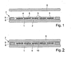
- FIG. 1 shows a first and FIG. 2 a second phase of producing a photovoltaic module and in particular of producing a first embodiment of an edge seal according to the invention in schematic cross-sectional representations.
- a cover glass 1 was placed on a laying table (not shown) and a first heat-activatable adhesive layer 2 in the form of an EVA film was placed thereon.
- a number of solar cells 3 were then placed on this first adhesive layer 2 and electrically connected to one another by means of soldering strips (not shown) in order to form a solar cell layer 4 form.
- a second EVA film was applied as a further adhesive layer 5 to this solar cell layer 4.
- a backsheet 6 is placed on the solar cell layer 4 and the second adhesive layer 5, according to the invention around the solar cell layer 4 and the two adhesive layers 2, 5 circumferentially applied a strand body 7 on the edge region of the cover glass 1, said strand body 7 here an inner core 8, which is mechanically weak, and a surrounding this core 8 jacket layer 9 is made.
- the cladding layer 9 consists of a heat-activatable adhesive, viscous under the action of heat.
- FIG. 2 shows the finished laminated photovoltaic module, consisting of the cover glass 1, embedded in a transparent and crosslinked adhesive layer 10 solar cell layer 4, the backsheet 6 and the edge seal 7 formed with core 8 and shell layer 9 edge seal.
- the core 8 of the extruded body 7 consists of a hot melt adhesive whose rheological properties are such that during the thermal process phases of the laminating a constantly higher viscosity than in the adhesive layers 2, 5 is present.
- the cladding layer 9 of the strand body 7 consists of isobutyl.
Abstract
Description
Die Erfindung betrifft ein Verfahren zum Herstellen eines Photovoltaikmoduls nach dem Oberbegriff der Ansprüche 1 und 2 sowie ein Photovoltaikmodul nach dem Oberbegriff der Ansprüche 9 und 10. Ein Photovoltaikmodul der vorliegenden Art wird im Wesentlichen aus einem transparenten Frontsubstrat, einem Rückseitensubstrat, einer dazwischengelegten Solarzellenschicht und einer wärmeaktivierbaren und hierbei erweichenden Kleberschicht zum Ausbilden eines laminierten Schichtverbundes zusammengesetzt.The invention relates to a method for producing a photovoltaic module according to the preamble of
Die zwischen dem Frontsubstrat, insbesondere einem Deckglas und dem Rückseitensubstrat, beispielsweise einer Rückseitenfolie oder einem Rückseitenglas befindliche Solarzellenschicht kann eine Dünnschicht-Solarzellenschicht oder eine Schicht aus einer Mehrzahl von nebeneinander angeordneten und miteinander verschalteten multi-, poly- oder monokristallinen Solarzellen sein. Die außerdem zwischen dem Frontsubstrat und dem Rückseitensubstrat vorgesehene wärmeaktivierbare Kleberschicht wird beispielsweise in Form zweier oberhalb und unterhalb der Solarzellenschicht angeordneter Kleberfolien zwischen das Frontsubstrat und das Rückseitensubstrat eingebracht. Diese Kleberfolien bestehen in der Regel aus einem transparenten thermoreaktiven Adhäsivstoff wie Ethylenvenylacetat (EVA) oder einem transparenten thermoplastischen Werkstoff.The solar cell layer located between the front substrate, in particular a cover glass and the rear side substrate, for example a backsheet or a backside glass, may be a thin-film solar cell layer or a layer of a plurality of multi, poly or monocrystalline solar cells arranged side by side and interconnected. The heat-activatable adhesive layer, which is also provided between the front substrate and the rear-side substrate, is introduced, for example, in the form of two adhesive films arranged above and below the solar cell layer, between the front substrate and the rear-side substrate. These adhesive films are usually made of a transparent thermo-reactive adhesive such as ethylene vinyl acetate (EVA) or a transparent thermoplastic material.
Durch Laminieren des aus Frontsubstrat, Solarzellenschicht, Kleberschicht und Rückseitensubstrat bestehenden Schichtstapels unter Druck- und Wärmeeinwirkung entsteht aufgrund der Aktivierung der Kleberschicht ein laminierter Schichtverbund, der im wesentlichen das fertige Photovoltaikmodul ist. Die Solarzellenschicht ist nach dem Laminieren in einer klaren, dreidimensional vernetzten oder ausgehärteten, nicht mehr aufschmelzbaren Kunststoffschicht eingebettet. Mittels dieser Kunststoffschicht sind außerdem das Frontsubstrat und das Rückseitensubstrat fest miteinander verbunden, und die Solarzellen sind mitsamt ihrer Verschalung dazwischen bzw. darin fixiert. Dieser laminierte Schichtverbund stellt sicher, dass beim normalen ganzjährigen Einsatz von Photovoltaikmodulen im Freien auch langfristig nicht zu befürchten ist, dass die Solarzellenschicht mit Umgebungsfeuchte und Luftsauerstoff in Berührung kommt und hierdurch geschädigt wird.By laminating the layer stack consisting of the front substrate, solar cell layer, adhesive layer and back substrate under the effect of pressure and heat, a laminated layer composite, which is essentially the finished photovoltaic module, arises due to the activation of the adhesive layer. The solar cell layer is after lamination in a clear, three-dimensionally networked or hardened, no longer meltable plastic layer embedded. By means of this plastic layer, moreover, the front substrate and the back substrate are fixedly connected to each other, and the solar cells are fixed together with their casing therebetween. This laminated laminate ensures that during the normal year-round use of photovoltaic modules in the open air, there is no reason to fear in the long term that the solar cell layer will come into contact with ambient humidity and atmospheric oxygen and be damaged as a result.
Photovoltaikmodule mit einem Frontsubstrat, einer Solarzellenschicht und einem Rückseitensubstrat werden üblicherweise in einer Laminierpresse laminiert, wobei sie in eine bei geschlossener Presse luftdichte Kammer verbracht, dort mittels Heizplatten und dergleichen erwärmt sowie mittels einer die Kammer horizontal unterteilenden flexiblen Membran mit dem zum Laminieren notwendigen Druck beaufschlagt werden. Hierzu wird die Kammer in der Regel evakuiert, um Lufteinschlüsse in der beim Laminieren erweichenden Kleberschicht zu vermeiden sowie etwa entstehende Prozessgase und Legeluft aus dem Inneren des Schichtstapels herauszuziehen, bevor die Kleberschicht vernetzt bzw. aushärtet. Ein Beispiel für ein solches Verfahren findet sich in der
Der eigentliche Laminiervorgang dauert eine gewisse Zeit, bis das Vernetzen bzw. Aushärten der Kleberschicht abgeschlossen und infolgedessen ein Wärmeeintrag in die Kleberschicht sowie in der Regel auch eine Auflast auf den Schichtverbund nicht mehr notwendig ist. Diese Zeitdauer hängt von den verwendeten Materialien ab und kann daher nicht prozesstechnisch verkürzt werden. Gleichzeitig handelt es sich beim Laminiervorgang um denjenigen Prozessschritt bei der Herstellung von Photovoltaikmodulen, der die Geschwindigkeit der gesamten Anlage limitiert. In der
Ein anderer Ansatz zur Beschleunigung der Herstellung von Photovoltaikmodulen der vorliegenden Art ist in der
Die zum Laminieren von Photovoltaikmodulen verwendeten Klebermaterialien besitzen in aller Regel hochadhäsive Eigenschaften, sobald sie aktiviert werden. Dies gilt insbesondere im erweichten, jedoch noch nicht vernetzten bzw. ausgehärteten Zustand. Da das Laminieren nicht nur durch Wärmeeintrag in den Schichtverbund, sondern auch durch Einwirken einer Auflast auf den Schichtverbund erfolgt, besteht immer die Gefahr, dass Material der erweichten Kleberschicht randseitig zwischen dem Frontsubstrat, beispielsweise einem Deckglas und dem Rückseitensubstrat, insbesondere einer Rückseitenfolie austritt, also mehr oder weniger zwischen diesen Schichten seitlich herausgequetscht wird. Dieses Material ist, wie erwähnt, jedoch hochadhäsiv, woraus sich hartnäckige Verschmutzungen der Laminierpresse und dort insbesondere der flexiblen Membran oder eines verwendeten Förderbandes ergeben. Solche Verschmutzungen limitieren nicht nur die Lebensdauer der verschmutzten Teile, sondern können gegebenenfalls zur Produktion von Ausschuss bei den nachfolgend prozessierten Photovoltaikmodulen führen.The adhesive materials used to laminate photovoltaic modules typically have high adhesive properties as soon as they are activated. This applies in particular in the softened, but not yet crosslinked or cured state. Since the laminating takes place not only by heat input into the layer composite, but also by the action of a load on the layer composite, there is always the risk that material of the softened adhesive layer emerges on the edge side between the front substrate, for example a cover glass and the back side substrate, in particular a back side film, ie more or less squeezed out laterally between these layers. However, this material is, as mentioned, highly adhesive, resulting in persistent contamination of the laminating and there especially the flexible membrane or a conveyor belt used. Such contamination not only limit the life of the soiled parts, but may possibly lead to the production of rejects in the subsequently processed photovoltaic modules.
Besondere Relevanz erhält diese Problematik beim oben beschrieben Kurztaktverfahren, das in der
Der vorliegenden Erfindung liegt daher die Aufgabe zugrunde, ein Verfahren zum Herstellen eines Photovoltaikmoduls der eingangs genannten Art sowie ein mit diesem Verfahren herstellbares Photovoltaikmodul vorzuschlagen, bei dem die Gefahr zumindest deutlich vermindert ist, dass beim Laminierprozess unbeabsichtigt Material der wärmeaktivierbaren Kleberschicht randseitig zwischen dem Frontsubstrat und dem Rückseitensubstrat austritt.The present invention is therefore based on the object to provide a method for producing a photovoltaic module of the type mentioned and a manufacturable with this method photovoltaic module, wherein the risk is at least significantly reduced that in the lamination unintentionally material of the heat-activatable adhesive layer edge between the front substrate and exits the back substrate.
Gelöst ist diese Aufgabe durch ein Verfahren mit den Merkmalen des Anspruchs 1 und durch ein Verfahren mit den Merkmalen des Anspruchs 2 sowie durch ein Photovoltaikmodul mit den Merkmalen des Anspruchs 9 und ein Photovoltaik-modul mit den Merkmalen des Anspruchs 10. Vorteilhafte Weiterbildungen der erfindungsgemäßen Verfahren finden sich in den Ansprüchen 3 bis 8; bevorzugte Ausgestaltungen der erfindungsgemäßen Photovoltaikmodule sind in den Ansprüchen 11 bis 16 niedergelegt.This object is achieved by a method having the features of
Nach der vorliegenden Erfindung wird das Photovoltaikmodul demnach mit einer Randversiegelung versehen, die durch einen randseitig umlaufenden, die Solarzellenschicht umgebenden Strangkörper zwischen dem Frontsubstrat und dem Rückseitensubstrat gebildet ist. Dieser Strangkörper bildet wie erwähnt eine Randversiegelung und damit eine Barriere gegen ein randseitiges Austreten der erweichten und gegebenenfalls sogar verflüssigten Kleberschicht beim Laminieren. Damit der Strangkörper eine solche Barrierewirkung hervorrufen kann, besteht er ebenfalls zumindest zum Teil aus einem wärmeaktivierbaren Klebermaterial, so dass er sich beim Laminieren sowohl einerseits mit dem Frontsubstrat als auch andererseits mit dem Rückseitensubstrat verbindet und so zuverlässig verhindert, dass Material von der wärmeaktivierbaren Kleberschicht aus dem Inneren des Schichtverbundes nach außen treten kann. Gleichzeitig wird erfindungsgemäß sichergestellt, dass das wärmeaktivierbare Klebermaterial des Strangkörpers entweder nicht oder im Vergleich zur wärmeaktivierbaren Kleberschicht langsamer und/oder erst bei höheren Temperaturen erweicht, oder aber dass das wärmeaktivierbare Klebermaterial des Strangkörpers im Vergleich zur wärmeaktivierbaren Kleberschicht bei gleicher Temperatur eine höhere Viskosität besitzt. Somit ist selbst dann, wenn die eigentliche wärmeaktivierbare Kleberschicht des Photovoltaikmoduls in einen sehr weichen oder sogar flüssigen Zustand gerät, die Barrierewirkung des umgebenden Strangkörpers aufgrund seiner geringeren Erweichung oder aufgrund seiner höheren Viskosität sichergestellt.According to the present invention, the photovoltaic module is thus provided with an edge seal, which is formed by a peripherally encircling, surrounding the solar cell layer extruded body between the front substrate and the back substrate. As already mentioned, this extruded body forms an edge seal and thus a barrier against leakage on the edge of the softened and optionally even liquefied adhesive layer during lamination. In order for the extruded body to be able to produce such a barrier effect, it also consists at least in part of a heat-activatable adhesive material, so that it laminates both on the one hand with the front substrate on the other hand connects to the back substrate and so reliably prevents material from the heat-activatable adhesive layer from the interior of the laminate can pass outward. At the same time, it is ensured according to the invention that the heat-activatable adhesive material of the extruded body does not soften or slows down more slowly and / or only at higher temperatures than the heat-activatable adhesive layer, or else that the heat-activatable adhesive material of the extruded body has a higher viscosity compared to the heat-activatable adhesive layer at the same temperature. Thus, even if the actual heat-activatable adhesive layer of the photovoltaic module gets into a very soft or even liquid state, the barrier effect of the surrounding extrudate is ensured due to its lower softening or due to its higher viscosity.
Um beiden Anforderungen an den Strangkörper optimal entsprechen zu können, also eine hohe Adhäsionswirkung gegen einerseits das Frontsubstrat und andererseits das Rückseitensubstrat bereitzustellen und dennoch eine höhere Stabilität durch geringere Erweichung oder höhere Viskosität als die wärmeaktivierbare Kleberschicht und somit eine Barrierewirkung sicherzustellen, kann nach einer bevorzugten Weiterbildung der vorliegenden Erfindung der Strangkörper aus einem Kern und einer diesen einhüllenden Mantelschicht aus wärmeaktivierbarem Klebermaterial zusammengesetzt sein. Der Kern ist dann für die Stabilität und die damit zusammenhängende Barrierewirkung zuständig, während die Mantelschicht mit einer besonders hohen und früh einsetzenden Adhäsionswirkung versehen sein kann. Beispielsweise kann die Mantelschicht aus einem Polyisobutyl-Werkstoff oder einem Epoxidharz bestehen. Der Kern kann beispielsweise aus einem strangpressbaren, wenig nachgiebigen Material, wie einen temperaturstabilen Kunststoff oder einem Metall, insbesondere Kupfer, Aluminium oder Zinn bestehen.In order to be able to optimally meet both requirements of the extruded body, ie to provide a high adhesion to the front substrate on the one hand and the back substrate on the other hand, and to ensure greater stability through lower softening or higher viscosity than the heat-activatable adhesive layer and thus a barrier effect, according to a preferred development According to the present invention, the extruded body may be composed of a core and a shell layer of heat-activatable adhesive material enveloping the same. The core is then responsible for the stability and the associated barrier effect, while the cladding layer can be provided with a particularly high and early onset of adhesion. For example, the cladding layer may consist of a polyisobutyl material or an epoxy resin. The core may for example consist of an extrudable, low-yielding material, such as a temperature-stable plastic or a metal, in particular copper, aluminum or tin.
Eine andere bevorzugte Ausgestaltung der vorliegenden Erfindung besteht darin, dass als wärmeaktivierbares Klebermaterial für den Strangkörper dasjenige Material verwendet wird, aus dem auch die wärmeaktivierbare Kleberschicht des Schichtverbundes besteht. Um hierbei die erfindungsgemäßen Unterschiede zwischen dem randversiegelnden Strangkörper und der innenliegenden Kleberschicht zu erzielen, kann dieses Klebermaterial mit Beimischungen versehen werden, die die Aktivierbarkeit, die Adhäsionswirkung und/oder die Viskosität des Materials beeinflussen. Dies ist besonders gut bei thermoplastischen Elastomeren umzusetzen, deren Viskosität durch Beimischungen gezielt veränderbar ist. Jedoch auch andere Materialien für die Kleberschicht, wie beispielsweise EVA, TPO, TPU, PVB und lonomer können auf diese Art und Weise zusätzlich als Strangkörper im Sinne der vorliegenden Erfindung verwendet werden. Neben den Vorteilen der chemischen Verträglichkeit mit der Kleberschicht und denselben verwitterungsbeständigen Eigenschaften ergibt sich hierbei außerdem der Vorteil, dass der Strangkörper zur Randversiegelung ebenso transparent ist, wie die eigentliche Kleberschicht, also zum einen im fertigen Photovoltaikmodul unsichtbar ist, und zum anderen die Lichteinstrahlung in das Photovoltaikmodul nicht stört.Another preferred embodiment of the present invention is that is used as the heat-activatable adhesive material for the extruded body that material from which the heat-activatable adhesive layer of the Layer composite exists. In order to achieve the differences according to the invention between the edge-sealing extruded body and the inner adhesive layer, this adhesive material can be provided with admixtures which influence the activability, the adhesion and / or the viscosity of the material. This is particularly well implemented in thermoplastic elastomers whose viscosity can be selectively changed by admixtures. However, other materials for the adhesive layer, such as, for example, EVA, TPO, TPU, PVB and ionomer, can additionally be used as extrudates for the purposes of the present invention. In addition to the advantages of chemical compatibility with the adhesive layer and the same weather-resistant properties, this also has the advantage that the extruded body for edge sealing is just as transparent as the actual adhesive layer, so on the one hand in the finished photovoltaic module is invisible, and on the other hand, the light into the Photovoltaic module does not bother.
Um bei identischem Material für die wärmeaktivierbare Kleberschicht und das wärmeaktivierbare Klebermaterial des Strangkörpers die erfindungsgemäßen Unterschiede zwischen dem Strangkörper und der innenliegenden Kleberschicht ohne Beimischungen zu erzielen, kann im Rahmen der vorliegenden Erfindung alternativ vorgesehen sein, als wärmeaktivierbares Klebermaterial des Strangkörpers das Material der wärmeaktivierbaren Kleberschicht mit einer höheren Schichtdicke zu verwenden. Hierbei sollte diese höhere Schichtdicke dem 1,1-fachen bis 3-fachen, vorzugsweise dem 1,2-fachen bis 1,5-fachen der Schichtdicke der innenliegenden Kleberschicht entsprechen. Durch die randseitige Materialanhäufung ergibt sich bei geeigneten Klebermaterialien die gewünschte Barrierewirkung, da das aufgedickte Material langsamer erweicht und insofern bei geeigneter Wahl der Prozessparameter eine höhere Viskosität aufweist als die innenliegende Kleberschicht.In order to achieve the inventive differences between the extruded body and the inner adhesive layer without admixtures with identical material for the heat-activatable adhesive layer and the heat-activatable adhesive material of the strand, can be provided in the context of the present invention as an alternative, as heat-activatable adhesive material of the extruded body, the material of the heat-activated adhesive layer to use a higher layer thickness. In this case, this higher layer thickness should correspond to 1.1 times to 3 times, preferably 1.2 times to 1.5 times, the layer thickness of the inner adhesive layer. Due to the accumulation of material at the edge, the desired barrier effect results for suitable adhesive materials, since the thickened material softens more slowly and, with a suitable choice of process parameters, has a higher viscosity than the internal adhesive layer.
Im Rahmen der vorliegenden Erfindung sind selbstverständlich auch andere Materialien für den erfindungsgemäßen Strangkörper einsetzbar, wie beispielsweise lonomer-Barriere-Material, PU-Hotmelt, Materialien auf Basis von TPS und PIV (Polyisobutylen), aufgeschäumte thermoplastische Elastomere und dergleichen.In the context of the present invention, of course, other materials for the extruded body according to the invention can be used, such as ionomer barrier material, PU hotmelt, materials based on TPS and PIV (polyisobutylene), foamed thermoplastic elastomers and the like.
Erfindungsgemäße Photovoltaikmodule besitzen vorzugsweise als Frontsubstrat ein Deckglas und als Rückseitensubstrat eine Rückseitenfolie. Hierauf ist die vorliegende Erfindung jedoch nicht beschränkt; sie umfasst vielmehr auch Photovoltaikmodule und Verfahren zur Herstellung eines solchen, die mit einem Deckglas und einem Rückseitenglas versehen oder mit einer transparenten Deckfolie und einer Rückseitenfolie aufgebaut sind. Die Erfindung eignet sich also für alle bekannten Arten von Photovoltaikmodulen: Glas-Glas-Module, Glas-Folien-Module und Folien-Folien-Module. Auch andere Substratkombinationen sind denkbar und von der vorliegenden Erfindung umfasst, beispielsweise ein Modul mit einer Deckfolie und einem Rückseitenglas, oder ein Modul mit einer nicht aus Glas bestehenden Rückseitenplatte und einem Deckglas oder einer Deckfolie.Photovoltaic modules according to the invention preferably have a cover glass as the front substrate and a backsheet as the back substrate. However, the present invention is not limited thereto; Rather, it also includes photovoltaic modules and methods for making such, which are provided with a cover glass and a back glass or constructed with a transparent cover sheet and a backsheet. The invention is thus suitable for all known types of photovoltaic modules: glass-glass modules, glass-film modules and film-film modules. Also other substrate combinations are conceivable and encompassed by the present invention, for example a module with a cover sheet and a backside glass, or a module with a non-glass back sheet and a coverslip or cover sheet.
Ein Ausführungsbeispiel für ein erfindungsgemäß ausgestaltetes Verfahren zum Herstellen eines Photovoltaikmoduls wird im folgenden anhand der beigefügten Zeichnungen näher beschrieben und erläutert. Es zeigen:
-
Figur 1 -
Figur 2Figur 1
-
FIG. 1 a schematic section through a photovoltaic module with cover glass and backsheet in a first assembly phase; -
FIG. 2 the cut outFIG. 1 in a second assembly phase.
Bevor nun eine Rückseitenfolie 6 auf die Solarzellenschicht 4 bzw. die zweite Kleberschicht 5 aufgelegt wird, wird erfindungsgemäß rund um die Solarzellenschicht 4 und die beiden Kleberschichten 2, 5 umlaufend ein Strangkörper 7 auf den Randbereich des Deckglases 1 aufgebracht, wobei dieser Strangkörper 7 hier aus einem innenliegenden Kern 8, der mechanisch wenig nachgiebig ist, und einer diesen Kern 8 umgebenden Mantelschicht 9 besteht. Die Mantelschicht 9 besteht aus einem wärmeaktivierbar adhäsiven, unter Wärmeeinwirkung viskosen Material.Before now a
Bei einem Versuch an einem in den
Claims (16)
dadurch gekennzeichnet,
dass zur Randversiegelung des Photovoltaikmoduls ein randseitig umlaufender, die Solarzellenschicht (3) umgebender Strangkörper (7) aus oder mit einem wärmeaktivierbaren Klebermaterial (9) zwischen das Frontsubstrat (1) und das Rückseitensubstrat (6) gelegt wird, wobei das wärmeaktivierbare Klebermaterial (9) des Strangkörpers (7) qualitativ und/oder quantitativ so gewählt wird, dass es nicht oder im Vergleich zur wärmeaktivierbaren Kleberschicht (2) langsamer und/oder erst bei höheren Temperaturen erweicht.A method of manufacturing a photovoltaic module consisting essentially of a transparent front substrate (1), a backside substrate (6), a solar cell layer (3) interposed therebetween, and a heat-activatable and thereby softening adhesive layer (2) for forming a laminated laminar composite,
characterized,
in that, for the edge sealing of the photovoltaic module, a peripheral body (7) surrounding the solar cell layer (3) is placed between the front substrate (1) and the back substrate (6) from or with a heat-activatable adhesive material (9), the heat-activatable adhesive material (9) the strand body (7) is selected qualitatively and / or quantitatively so that it does not soften or, compared to the heat-activatable adhesive layer (2), slower and / or only at higher temperatures.
dadurch gekennzeichnet,
dass zur Randversiegelung des Photovoltaikmoduls ein randseitig umlaufender, die Solarzellenschicht (3) umgebender Strangkörper (7) aus oder mit einem wärmeaktivierbaren Klebermaterial (9) zwischen das Frontsubstrat (1) und das Rückseitensubstrat (6) gelegt wird, wobei das wärmeaktivierbare Klebermaterial (9) des Strangkörpers (7) so gewählt wird, dass es bei den zum Aktivieren der Kleberschicht (2) verwendeten Temperaturen eine im Vergleich zur wärmeaktivierbaren Kleberschicht (2) höhere Viskosität besitzt.A method of manufacturing a photovoltaic module consisting essentially of a transparent front substrate (1), a backside substrate (6), a solar cell layer (3) interposed therebetween, and a heat-activatable and thereby softening adhesive layer (2) for forming a laminated laminar composite,
characterized,
in that, for the edge sealing of the photovoltaic module, a peripheral body (7) surrounding the solar cell layer (3) is placed between the front substrate (1) and the back substrate (6) from or with a heat-activatable adhesive material (9), the heat-activatable adhesive material (9) of the extruded body (7) is selected so that it has a higher viscosity compared to the heat-activatable adhesive layer (2) in the temperatures used to activate the adhesive layer (2).
dadurch gekennzeichnet,
dass als wärmeaktivierbares Klebermaterial (9) das Material der wärmeaktivierbaren Kleberschicht (2) mit Beimischungen verwendet wird, welche die Aktivierbarkeit, die Adhäsionswirkung und/oder die Viskosität beeinflussen.Method according to one of claims 1 or 2,
characterized,
in that as heat-activatable adhesive material (9) the material of the heat-activatable adhesive layer (2) is used with admixtures which influence the activability, the adhesion and / or the viscosity.
dadurch gekennzeichnet,
dass als wärmeaktivierbares Klebermaterial (9) das Material der wärmeaktivierbaren Kleberschicht (2) mit einer höheren Schichtdicke verwendet wird.Method according to one of claims 1 or 2,
characterized,
that the material of the heat-activatable adhesive layer (2) is used at a higher layer thickness than heat-activatable adhesive material (9).
dadurch gekennzeichnet,
dass ein Strangkörper (7) aus oder mit einem wärmeaktivierbaren Klebermaterial (9) verwendet wird, dessen Schichtdicke dem 1,1-fachen bis 3-fachen, vorzugsweise dem 1,2-fachen bis 1,5-fachen der Schichtdicke der wärmeaktivierbaren Kleberschicht (2) entspricht.Method according to claim 4,
characterized,
in that a strand body (7) made of or with a heat-activatable adhesive material (9) is used whose layer thickness is 1.1 times to 3 times, preferably 1.2 times to 1.5 times, the layer thickness of the heat-activatable adhesive layer (FIG. 2) corresponds.
dadurch gekennzeichnet,
dass ein Strangkörper (7) verwendet wird, der aus einem Kern (8) und einer diesen einhüllenden Mantelschicht (9) aus wärmeaktivierbarem Klebermaterial besteht.Method according to at least one of claims 1 to 5,
characterized,
in that a strand body (7) is used, which consists of a core (8) and a shell layer (9) of heat-activatable adhesive material enveloping it.
dadurch gekennzeichnet,
dass die Kleberschicht (2) des Photovoltaikmoduls in einer ersten Laminierpresse nur so weit aktiviert und erweicht wird, bis die Solarzellenschicht (3) im Schichtverbund gegen die Umgebung verkapselt ist, und dass das Photovoltaikmodul dann von der ersten Laminierpresse zum weiteren Prozessieren in einen zweiten Laminator verbracht wird.Method according to at least one of claims 1 to 6,
characterized,
that the adhesive layer (2) of the photovoltaic module is activated and softened only in a first laminating press until the solar cell layer (3) is encapsulated in the layer composite against the environment, and that the photovoltaic module is then transferred from the first laminating press for further processing in a second laminator.
dadurch gekennzeichnet,
dass als Frontsubstrat ein Deckglas (1) und als Rückseitensubstrat eine Rückseitenfolie (6) verwendet wird.Method according to at least one of claims 1 to 7,
characterized,
in that a cover glass (1) is used as the front substrate and a backsheet (6) is used as the back substrate.
dadurch gekennzeichnet,
dass zwischen dem Frontsubstrat (1) und dem Rückseitensubstrat (6) ein randseitig umlaufender, die Solarzellenschicht (3) umgebender Strangkörper (7) aus oder mit einem wärmeaktivierbaren Klebermaterial (9) vorhanden ist, das nicht oder im Vergleich zur wärmeaktivierbaren Kleberschicht (2) langsamer und/oder erst bei höheren Temperaturen erweicht.Photovoltaic module, in particular produced in a method according to one of Claims 1 to 8, having a transparent front substrate (1), a backside substrate (6), a solar cell layer (3) interposed therebetween and an adhesive layer (2) heat-activatable and softening to form a laminated layer composite )
characterized,
in that between the front substrate (1) and the rear side substrate (6) there is a peripheral body (7) surrounding the solar cell layer (3) or with a heat-activatable adhesive material (9) which does not or in comparison with the heat-activatable adhesive layer (2). slows down and / or softens only at higher temperatures.
dadurch gekennzeichnet,
dass zwischen dem Frontsubstrat (1) und dem Rückseitensubstrat (6) ein randseitig umlaufender, die Solarzellenschicht (3) umgebender Strangkörper (7) aus oder mit einem wärmeaktivierbaren Klebermaterial (9) vorhanden ist, das bei den zum Aktivieren der Kleberschicht (2) verwendeten Temperaturen eine im Vergleich zur wärmeaktivierbaren Kleberschicht (2) höhere Viskosität besitzt.Photovoltaic module, in particular produced in a method according to one of Claims 1 to 8, having a transparent front substrate (1), a backside substrate (6), a solar cell layer (3) interposed therebetween and an adhesive layer (2) heat-activatable and softening to form a laminated layer composite )
characterized,
in that between the front substrate (1) and the rear side substrate (6) there is a peripheral body (7) surrounding the solar cell layer (3) or with a heat-activatable adhesive material (9) used in activating the adhesive layer (2) Temperatures has a higher viscosity compared to the heat-activatable adhesive layer (2).
dadurch gekennzeichnet,
dass das wärmeaktivierbare Klebermaterial (9) aus dem Material der wärmeaktivierbaren Kleberschicht (2) mit Beimischungen besteht, welche die Aktivierbarkeit, die Adhäsionswirkung und/oder die Viskosität beeinflussen.Photovoltaic module according to one of claims 9 or 10,
characterized,
in that the heat-activatable adhesive material (9) consists of the material of the heat-activatable adhesive layer (2) with admixtures which influence the activability, the adhesion action and / or the viscosity.
dadurch gekennzeichnet,
dass das wärmeaktivierbare Klebermaterial (9) aus dem Material der wärmeaktivierbaren Kleberschicht (2) mit einer höheren Schichtdicke besteht.Photovoltaic module according to one of claims 9 or 10,
characterized,
in that the heat-activatable adhesive material (9) consists of the material of the heat-activatable adhesive layer (2) with a higher layer thickness.
dadurch gekennzeichnet,
dass die Schichtdicke des wärmeaktivierbaren Klebermaterials (9) dem 1,1-fachen bis 3-fachen, vorzugsweise dem 1,2-fachen bis 1,5-fachen der Schichtdicke der wärmeaktivierbaren Kleberschicht (2) entspricht.Photovoltaic module according to claim 12,
characterized,
in that the layer thickness of the heat-activatable adhesive material (9) corresponds to 1.1 times to 3 times, preferably 1.2 times to 1.5 times, the layer thickness of the heat-activatable adhesive layer (2).
dadurch gekennzeichnet,
dass der Strangkörper (7) aus einem Kern (8) und einer diesen einhüllenden Mantelschicht (9) aus wärmeaktivierbarem Klebermaterial besteht.Photovoltaic module according to at least one of claims 9 to 13,
characterized,
in that the extruded body (7) consists of a core (8) and a cladding layer (9) enveloping it of heat-activatable adhesive material.
dadurch gekennzeichnet,
dass der Strangkörper (7) zumindest teilweise aus einem thermoplastischen. Elastomer besteht.Photovoltaic module according to at least one of claims 9 to 14,
characterized,
that the extruded body (7) at least partially made of a thermoplastic. Elastomer exists.
dadurch gekennzeichnet,
dass das Frontsubstrat ein Deckglas (1) und das Rückseitensubstrat eine Rückseitenfolie (6) ist.Photovoltaic module according to at least one of claims 9 to 15,
characterized,
in that the front substrate is a cover glass (1) and the rear substrate is a backsheet (6).
Priority Applications (4)
| Application Number | Priority Date | Filing Date | Title |
|---|---|---|---|
| TW100135241A TW201228011A (en) | 2010-10-30 | 2011-09-29 | Photovoltaic module and method for the production thereof |
| US13/282,607 US20120103397A1 (en) | 2010-10-30 | 2011-10-27 | Photovoltaic module and method for the production thereof |
| CN201110335230XA CN102456774A (en) | 2010-10-30 | 2011-10-28 | Photovoltaic module and method for the production thereof |
| JP2011238898A JP2012099818A (en) | 2010-10-30 | 2011-10-31 | Photovoltaic module and method for production thereof |
Applications Claiming Priority (1)
| Application Number | Priority Date | Filing Date | Title |
|---|---|---|---|
| DE102010050187A DE102010050187A1 (en) | 2010-10-30 | 2010-10-30 | Method for producing a edge seal of photovoltaic modules and use of a strand body for this purpose |
Publications (2)
| Publication Number | Publication Date |
|---|---|
| EP2448010A2 true EP2448010A2 (en) | 2012-05-02 |
| EP2448010A3 EP2448010A3 (en) | 2015-05-06 |
Family
ID=44720503
Family Applications (2)
| Application Number | Title | Priority Date | Filing Date |
|---|---|---|---|
| EP20110003759 Withdrawn EP2448010A3 (en) | 2010-10-30 | 2011-05-06 | Method for producing an edge sealing for photovoltaic modules and use of an extrusion body for same and corresponding photovoltaic module |
| EP11007701.3A Withdrawn EP2448011A3 (en) | 2010-10-30 | 2011-09-22 | Method for producing an edge sealing for photovoltaic modules and use of an extrusion body for same |
Family Applications After (1)
| Application Number | Title | Priority Date | Filing Date |
|---|---|---|---|
| EP11007701.3A Withdrawn EP2448011A3 (en) | 2010-10-30 | 2011-09-22 | Method for producing an edge sealing for photovoltaic modules and use of an extrusion body for same |
Country Status (6)
| Country | Link |
|---|---|
| US (1) | US20120103397A1 (en) |
| EP (2) | EP2448010A3 (en) |
| JP (1) | JP2012099818A (en) |
| CN (1) | CN102456774A (en) |
| DE (1) | DE102010050187A1 (en) |
| TW (1) | TW201228011A (en) |
Cited By (3)
| Publication number | Priority date | Publication date | Assignee | Title |
|---|---|---|---|---|
| WO2014201318A1 (en) * | 2013-06-14 | 2014-12-18 | Corning Incorporated | Method of manufacturing laminated glass articles with improved edge condition |
| CN110521006A (en) * | 2017-04-14 | 2019-11-29 | 梅耶博格(瑞士)股份公司 | Photovoltaic module, the method for photovoltaic sealant and production photovoltaic module |
| EP3444849B1 (en) * | 2016-04-14 | 2021-10-20 | Gree Electric Appliances, Inc. of Zhuhai | Double glass assembly |
Families Citing this family (14)
| Publication number | Priority date | Publication date | Assignee | Title |
|---|---|---|---|---|
| CN108512508B (en) * | 2012-06-04 | 2020-12-01 | 夏普株式会社 | Solar cell module |
| CN102751355A (en) * | 2012-07-20 | 2012-10-24 | 中利腾晖光伏科技有限公司 | Anti-overflow-type crystalline silicon solar energy assembly |
| JP2014086613A (en) * | 2012-10-25 | 2014-05-12 | Kyocera Corp | Photoelectric conversion module |
| DE102014204125B4 (en) | 2014-03-06 | 2018-09-13 | Solibro Hi-Tech Gmbh | Laminating apparatus and method for producing a laminate |
| TW201537420A (en) * | 2014-03-28 | 2015-10-01 | Ghitron Technology Co Ltd | Black frame border reinforcing structure of glass substrate |
| CH710936A2 (en) * | 2015-04-01 | 2016-10-14 | Bs2 Ag | A method for producing a solar cell module and a solar cell module. |
| DE102016103998A1 (en) * | 2016-03-04 | 2017-09-07 | Hanwha Q.CELLS GmbH | Photovoltaic module laminate and a method of making a photovoltaic module laminate |
| CN109119501A (en) * | 2017-06-23 | 2019-01-01 | 上银光电股份有限公司 | Rimless thin-film solar cells packaging body |
| TWI661668B (en) * | 2017-07-25 | 2019-06-01 | 海力雅集成股份有限公司 | Solar module |
| JP7303632B2 (en) * | 2017-09-27 | 2023-07-05 | 積水化学工業株式会社 | laminated glass |
| DE102017125226B4 (en) * | 2017-10-27 | 2021-02-18 | Hanwha Q Cells Gmbh | Method of repairing a solar panel and solar panel |
| US20210308991A1 (en) * | 2020-04-02 | 2021-10-07 | Pleotint, Llc | Interlayers and laminates incorporating the interlayers |
| CN112635598B (en) * | 2020-12-17 | 2022-05-13 | 泰州隆基乐叶光伏科技有限公司 | Solar cell module and packaging method thereof |
| WO2023210490A1 (en) * | 2022-04-28 | 2023-11-02 | 京セラ株式会社 | Solar cell module |
Citations (2)
| Publication number | Priority date | Publication date | Assignee | Title |
|---|---|---|---|---|
| EP1997614A2 (en) | 2007-05-30 | 2008-12-03 | Robert Bürkle GmbH | Method and device for laminating mainly plate-shaped workpieces with the use of pressure and heat |
| DE102007025380A1 (en) | 2007-05-30 | 2008-12-04 | Robert Bürkle GmbH | Multi-opening lamination press |
Family Cites Families (11)
| Publication number | Priority date | Publication date | Assignee | Title |
|---|---|---|---|---|
| JPS5328751B2 (en) * | 1974-11-27 | 1978-08-16 | ||
| BE876681A (en) * | 1978-06-14 | 1979-11-30 | Bfg Glassgroup | PROCESS FOR MANUFACTURING A PANEL INCLUDING AT LEAST ONE PHOTOVOLTAIC CELL AND PANEL INCLUDING AT LEAST ONE SUCH CELL |
| US5733382A (en) * | 1995-12-18 | 1998-03-31 | Hanoka; Jack I. | Solar cell modules and method of making same |
| DE10050612A1 (en) * | 2000-10-12 | 2002-05-02 | Dorma Gmbh & Co Kg | Solar module with top and bottom panes whose spacing can be precisely adjusted and kept |
| JP4076742B2 (en) * | 2001-07-13 | 2008-04-16 | シャープ株式会社 | Solar cell module |
| AU2002365087A1 (en) * | 2001-10-23 | 2003-06-23 | Bp Corporation North America Inc. | Sealed thin film photovoltaic modules |
| JP5028804B2 (en) * | 2006-01-19 | 2012-09-19 | ソニー株式会社 | Functional device |
| WO2009029897A2 (en) * | 2007-08-29 | 2009-03-05 | Robert Stancel | Edge mountable electrical connection assembly |
| ITMI20071903A1 (en) * | 2007-10-04 | 2009-04-05 | Getters Spa | METHOD FOR THE PRODUCTION OF SOLAR PANELS THROUGH THE USE OF A POLYMER TRISTRATE INCLUDING A COMPOSITE GETTER SYSTEM |
| US20090159117A1 (en) * | 2007-12-20 | 2009-06-25 | Truseal Technologies, Inc. | Hot melt sealant containing desiccant for use in photovoltaic modules |
| JP4869408B2 (en) * | 2008-01-15 | 2012-02-08 | アフィニティー株式会社 | Solar cell module and manufacturing method thereof |
-
2010
- 2010-10-30 DE DE102010050187A patent/DE102010050187A1/en not_active Withdrawn
-
2011
- 2011-05-06 EP EP20110003759 patent/EP2448010A3/en not_active Withdrawn
- 2011-09-22 EP EP11007701.3A patent/EP2448011A3/en not_active Withdrawn
- 2011-09-29 TW TW100135241A patent/TW201228011A/en unknown
- 2011-10-27 US US13/282,607 patent/US20120103397A1/en not_active Abandoned
- 2011-10-28 CN CN201110335230XA patent/CN102456774A/en active Pending
- 2011-10-31 JP JP2011238898A patent/JP2012099818A/en not_active Withdrawn
Patent Citations (2)
| Publication number | Priority date | Publication date | Assignee | Title |
|---|---|---|---|---|
| EP1997614A2 (en) | 2007-05-30 | 2008-12-03 | Robert Bürkle GmbH | Method and device for laminating mainly plate-shaped workpieces with the use of pressure and heat |
| DE102007025380A1 (en) | 2007-05-30 | 2008-12-04 | Robert Bürkle GmbH | Multi-opening lamination press |
Cited By (5)
| Publication number | Priority date | Publication date | Assignee | Title |
|---|---|---|---|---|
| WO2014201318A1 (en) * | 2013-06-14 | 2014-12-18 | Corning Incorporated | Method of manufacturing laminated glass articles with improved edge condition |
| US10286630B2 (en) | 2013-06-14 | 2019-05-14 | Corning Incorporated | Method of manufacturing laminated glass articles with improved edge condition |
| US11027524B2 (en) | 2013-06-14 | 2021-06-08 | Corning Incorporated | Method of manufacturing laminated glass articles with improved edge condition |
| EP3444849B1 (en) * | 2016-04-14 | 2021-10-20 | Gree Electric Appliances, Inc. of Zhuhai | Double glass assembly |
| CN110521006A (en) * | 2017-04-14 | 2019-11-29 | 梅耶博格(瑞士)股份公司 | Photovoltaic module, the method for photovoltaic sealant and production photovoltaic module |
Also Published As
| Publication number | Publication date |
|---|---|
| JP2012099818A (en) | 2012-05-24 |
| CN102456774A (en) | 2012-05-16 |
| EP2448010A3 (en) | 2015-05-06 |
| EP2448011A3 (en) | 2015-02-18 |
| EP2448011A2 (en) | 2012-05-02 |
| DE102010050187A1 (en) | 2012-05-03 |
| TW201228011A (en) | 2012-07-01 |
| US20120103397A1 (en) | 2012-05-03 |
Similar Documents
| Publication | Publication Date | Title |
|---|---|---|
| EP2448010A2 (en) | Method for producing an edge sealing for photovoltaic modules and use of an extrusion body for same and corresponding photovoltaic module | |
| EP2470327B1 (en) | Method and device for the bubble-free bonding of large-surface glass panes | |
| DE2923770C2 (en) | ||
| EP1953829B1 (en) | Method for manufacturing solar modules by roll laminating method | |
| AT505186A1 (en) | USE OF A PLASTIC COMPOSITE FOR THE MANUFACTURE OF PHOTOVOLTAIC MODULES | |
| EP1798027B1 (en) | Polyvinylacetal-containing sheet with uniform width | |
| EP1018166A1 (en) | Photovoltaic module and method for producing same | |
| EP2141018A2 (en) | Method and device for laminating mainly plate-shaped workpieces with the use of pressure and heat | |
| EP2251188A2 (en) | Press for laminating substantially board-shaped workpieces | |
| EP2719533A1 (en) | Insulating glazing unit | |
| DE3315331A1 (en) | METHOD FOR PRODUCING A MULTILAYER LAMINATE | |
| DE102007037891B4 (en) | Method for producing a curved glass cover or a curved glass fixed element for a vehicle roof | |
| DE112020002902T5 (en) | Laminated glazing with small radii of complex shape | |
| WO2014100905A1 (en) | Composite glass | |
| WO2009053321A2 (en) | Encapsulated solar cell | |
| DE102009020172A1 (en) | Press for laminating substantially plate-shaped workpieces | |
| EP3028854B1 (en) | Method for lamination and forming of solar modules on support structures | |
| WO2011041806A2 (en) | Vacuum element and method for producing the same | |
| DE102009059312A1 (en) | Solar cell arrangement for use in solar module, has photo-electric layers arranged on substrate material, and semi-finished part formed for encapsulation into module, where arrangement is fixed on gas-permeable substrate by adhesive layer | |
| WO2019068929A1 (en) | Method for the back-side covering of photovoltaic modules | |
| AT508399A1 (en) | METHOD FOR PRODUCING A SOLAR PANEL INSTALLED FROM LAYERS | |
| DE4015571A1 (en) | METHOD FOR PRODUCING A FILM FROM THERMOPLASTIC PLASTIC, FILM, PRODUCED BY THE PROCESS, AND COMPOSITE SAFETY GLASS, PRODUCED BY USING THE FILM | |
| DE102017119900A1 (en) | Arcuately curved translucent assembly, use and manufacturing method therefor | |
| AT508268A1 (en) | METHOD FOR PRODUCING A SOLAR PANEL INSTALLED FROM LAYERS | |
| EP3170661B1 (en) | Low pressure thin wall heat exchanger and method for producing same |
Legal Events
| Date | Code | Title | Description |
|---|---|---|---|
| PUAI | Public reference made under article 153(3) epc to a published international application that has entered the european phase |
Free format text: ORIGINAL CODE: 0009012 |
|
| AK | Designated contracting states |
Kind code of ref document: A2 Designated state(s): AL AT BE BG CH CY CZ DE DK EE ES FI FR GB GR HR HU IE IS IT LI LT LU LV MC MK MT NL NO PL PT RO RS SE SI SK SM TR |
|
| AX | Request for extension of the european patent |
Extension state: BA ME |
|
| PUAL | Search report despatched |
Free format text: ORIGINAL CODE: 0009013 |
|
| AK | Designated contracting states |
Kind code of ref document: A3 Designated state(s): AL AT BE BG CH CY CZ DE DK EE ES FI FR GB GR HR HU IE IS IT LI LT LU LV MC MK MT NL NO PL PT RO RS SE SI SK SM TR |
|
| AX | Request for extension of the european patent |
Extension state: BA ME |
|
| RIC1 | Information provided on ipc code assigned before grant |
Ipc: B32B 17/06 20060101ALI20150401BHEP Ipc: B32B 17/10 20060101ALI20150401BHEP Ipc: H01L 31/048 20140101AFI20150401BHEP Ipc: H01L 31/0203 20140101ALI20150401BHEP |
|
| STAA | Information on the status of an ep patent application or granted ep patent |
Free format text: STATUS: THE APPLICATION IS DEEMED TO BE WITHDRAWN |
|
| 18D | Application deemed to be withdrawn |
Effective date: 20151107 |