EP2447679A2 - Vorrichtung zur Befestigung eines Sensors - Google Patents
Vorrichtung zur Befestigung eines Sensors Download PDFInfo
- Publication number
- EP2447679A2 EP2447679A2 EP11007119A EP11007119A EP2447679A2 EP 2447679 A2 EP2447679 A2 EP 2447679A2 EP 11007119 A EP11007119 A EP 11007119A EP 11007119 A EP11007119 A EP 11007119A EP 2447679 A2 EP2447679 A2 EP 2447679A2
- Authority
- EP
- European Patent Office
- Prior art keywords
- housing
- sensor
- elastic element
- elastic
- fastening
- Prior art date
- Legal status (The legal status is an assumption and is not a legal conclusion. Google has not performed a legal analysis and makes no representation as to the accuracy of the status listed.)
- Granted
Links
- 238000003825 pressing Methods 0.000 claims abstract description 12
- 238000007789 sealing Methods 0.000 claims description 17
- 239000013013 elastic material Substances 0.000 claims description 3
- 238000000034 method Methods 0.000 description 4
- 238000004873 anchoring Methods 0.000 description 3
- 239000003599 detergent Substances 0.000 description 3
- XLYOFNOQVPJJNP-UHFFFAOYSA-N water Substances O XLYOFNOQVPJJNP-UHFFFAOYSA-N 0.000 description 3
- 230000000694 effects Effects 0.000 description 2
- 230000007704 transition Effects 0.000 description 2
- 229920000459 Nitrile rubber Polymers 0.000 description 1
- 239000004809 Teflon Substances 0.000 description 1
- 229920006362 Teflon® Polymers 0.000 description 1
- 230000006978 adaptation Effects 0.000 description 1
- 238000004026 adhesive bonding Methods 0.000 description 1
- 239000000956 alloy Substances 0.000 description 1
- 229910045601 alloy Inorganic materials 0.000 description 1
- 244000052616 bacterial pathogen Species 0.000 description 1
- 238000004140 cleaning Methods 0.000 description 1
- 230000006835 compression Effects 0.000 description 1
- 238000007906 compression Methods 0.000 description 1
- 230000001419 dependent effect Effects 0.000 description 1
- 238000011161 development Methods 0.000 description 1
- 230000018109 developmental process Effects 0.000 description 1
- 230000003670 easy-to-clean Effects 0.000 description 1
- 229920001971 elastomer Polymers 0.000 description 1
- 239000000806 elastomer Substances 0.000 description 1
- 238000005538 encapsulation Methods 0.000 description 1
- 230000002349 favourable effect Effects 0.000 description 1
- 238000002347 injection Methods 0.000 description 1
- 239000007924 injection Substances 0.000 description 1
- 238000001746 injection moulding Methods 0.000 description 1
- 238000005495 investment casting Methods 0.000 description 1
- 238000005304 joining Methods 0.000 description 1
- 239000000463 material Substances 0.000 description 1
- 239000002184 metal Substances 0.000 description 1
- 229920001296 polysiloxane Polymers 0.000 description 1
- 239000006228 supernatant Substances 0.000 description 1
Images


Classifications
-
- G—PHYSICS
- G01—MEASURING; TESTING
- G01D—MEASURING NOT SPECIALLY ADAPTED FOR A SPECIFIC VARIABLE; ARRANGEMENTS FOR MEASURING TWO OR MORE VARIABLES NOT COVERED IN A SINGLE OTHER SUBCLASS; TARIFF METERING APPARATUS; MEASURING OR TESTING NOT OTHERWISE PROVIDED FOR
- G01D11/00—Component parts of measuring arrangements not specially adapted for a specific variable
- G01D11/30—Supports specially adapted for an instrument; Supports specially adapted for a set of instruments
-
- F—MECHANICAL ENGINEERING; LIGHTING; HEATING; WEAPONS; BLASTING
- F15—FLUID-PRESSURE ACTUATORS; HYDRAULICS OR PNEUMATICS IN GENERAL
- F15B—SYSTEMS ACTING BY MEANS OF FLUIDS IN GENERAL; FLUID-PRESSURE ACTUATORS, e.g. SERVOMOTORS; DETAILS OF FLUID-PRESSURE SYSTEMS, NOT OTHERWISE PROVIDED FOR
- F15B15/00—Fluid-actuated devices for displacing a member from one position to another; Gearing associated therewith
- F15B15/20—Other details, e.g. assembly with regulating devices
- F15B15/28—Means for indicating the position, e.g. end of stroke
- F15B15/2892—Means for indicating the position, e.g. end of stroke characterised by the attachment means
Definitions
- the present invention relates to a device for attaching a sensor to a carrier component.
- Sensors have to be attached to machines, conveyors or the like in many areas of the industry. It is known to use the sensor to be fastened in a recess serving as a sensor receptacle in an elastic element. By compressing the elastic member from the outside, it is possible to hold the sensor in the elastic member.
- the elastic element can be clamped for this purpose, for example, between two pressing elements.
- the device comprises a housing receiving the elastic element, fastening means being provided for fastening the housing to the carrier component, which are additionally designed to bias the housing in the direction of a pressing surface of the carrier component, which in the region of the pressing surface consists of an opening in the carrier element Housing protruding protrusion portion of the elastic member is compressed while reducing the cross section of the recess.
- the anchoring of the overall arrangement does not take place by bracing the elastic element in a groove of the support member, but via separate fastening means and the housing, which is preferably not elastic.
- the housing with the accommodated elastic element is securely fastened to the carrier component.
- the holder for the sensor is thus formed in two parts, wherein one part is elastic and is received in the other part.
- no groove or other recess adapted to the fastening system must be provided on the support component, since only one, for example, flat pressure surface must be present for supporting the housing.
- the fastening system is thus particularly flexible and can be used on many different support components. Another advantage is that an encapsulation effect is achieved by the housing, which is favorable in terms of hygiene.
- a sealing element made of elastic material is provided at the opening of the housing.
- the housing is thus in sealing engagement with the pressing surface, so that no unwanted deposits in slots or cavities between the housing and the pressure surface can collect.
- the projection section of the elastic element has a concave end face.
- the fastening means may in particular comprise screws, which engage the housing and the carrier component.
- screws For example, threaded blind holes can be provided in the housing, into which screws can be screwed from a rear side of the carrier component. In this way, on the front of the support member as well as on the sensor holder itself any protruding screw heads or Avoid threaded sections, which are unfavorable in terms of hygiene.
- the housing can define a passage for the sensor, wherein the elastic element in the region of the passage forms an effective between the outer wall of the sensor to be fastened and the housing sealing lip. Due to the sealing lip thus any slots and cavities are avoided between the outer wall of the sensor and the housing, in which otherwise germ-promoting deposits could accumulate.
- the housing is half-shell-like and has convex outer surfaces.
- the outer surfaces are therefore preferably rounded and have a positive curvature everywhere, so that any water and detergent can flow well.
- the housing may be designed as an injection molded part, wherein the elastic element is encapsulated by the housing.
- overmolding increases the risk of creeping in of water or detergent into the sensor holder - e.g. due to the capillary effect - avoided, whereby a further increase in the standard of hygiene can be achieved.
- a device for fastening a sensor to a carrier component 11 which is shown only schematically, has an elastic element 13 in which a cylindrical feedthrough 15 for receiving a sensor 17 to be fastened (FIG. Fig. 2 ) is trained.
- the sensor 17 may be, for example, a non-threaded round sensor.
- the elastic element 13 is accommodated in a half-shell-like housing 19.
- the housing 19 encloses the elastic element 13 substantially completely, wherein, however, an opening 21 is provided on a lower fastening side 20 of the housing 19, from which protrudes a projection section 23 of the elastic element 13.
- an opening 21 is provided on a lower fastening side 20 of the housing 19, from which protrudes a projection section 23 of the elastic element 13.
- FIG. 2 shows the housing 19 further defines two aligned with the passage 15 of the elastic member 13 through openings 31 for the sensor to be fastened 17, wherein the elastic member 13 in the region of the passage openings 31 each have an effective between the outer wall of the sensor 17 and the housing 19 sealing lip 27 forms.
- the supernatant portion 23 of the elastic member 13 has a concave-shaped end face 25.
- the nature of the elastic member 13 may be adapted to the particular application in terms of mechanical strength and durability.
- the elastic element 13 may be made of an elastomer and preferably of NBR, silicone or Teflon.
- the elastic element 13 can be produced as a molded part.
- the housing 19 can be produced as a metal injection molding, in particular MIM, precision casting or as a machined part.
- the material of the housing 19 may be adapted to the particular application.
- the housing 19 may consist of a V4A alloy.
- connection of the elastic element 13 to the housing 19 can take place by joining the two parts to one another or preferably in that the elastic element 13 is encapsulated by the housing 19.
- Such an injection-molded arrangement is particularly resistant to, e.g. using high-pressure cleaner occurring high mechanical loads.
- a sealing element 29 is provided made of elastic material, which completely surrounds the opening 21.
- the sealing element 29 may be formed by a portion of the elastic element 13 itself or attached to the housing 19 as a separate component.
- the sealing element 29 may have a double sealing lip.
- Two threaded blind holes 33 of the housing 19, which are open toward the attachment side 20, serve to receive screws, not shown, which are used to fasten the housing 19 to the carrier component 11.
- the sensor 17 For attachment of the sensor 17 to the support member 11, the sensor 17 is first inserted through the passage openings 31 of the housing 19 and the passage 15 of the elastic member 13. Subsequently, the housing 19 by means of suitable fastening screws in the direction of a flat pressing surface 35 of the support member 11th drawn. At this time, the projecting projection portion 23 is compressed as shown in FIG Fig. 1 is illustrated by arrows. The pressure generated thereby is distributed in the elastic element 13. Since this is substantially completely enclosed by the inner wall of the housing 19 and the pressing surface 35, the pressure ultimately leads to a reduction of the cross section of the passage 15, which anchoring the sensor 17 in the implementation 15 causes.
- the sealing lips 27 are pressed firmly against the outer wall of the sensor 17, so that a reliable sealing transition between the sensor 17 and the housing 19 results.
- the screws pull the housing 19 with the sealing element 29 in advance firmly against the pressure surface 35, so that a reliable sealing transition between the support member 11 and the housing 19 results.
- the invention enables a simple and reliable attachment of sensors in hygienically sensitive areas.
Landscapes
- Physics & Mathematics (AREA)
- Engineering & Computer Science (AREA)
- Fluid Mechanics (AREA)
- Mechanical Engineering (AREA)
- General Engineering & Computer Science (AREA)
- General Physics & Mathematics (AREA)
- Measuring Fluid Pressure (AREA)
Abstract
Description
- Die vorliegende Erfindung betrifft eine Vorrichtung zur Befestigung eines Sensors an einem Trägerbauteil.
- Sensoren müssen in vielen Bereichen der Industrie an Maschinen, Transporteinrichtungen oder dergleichen angebracht werden. Es ist bekannt, den zu befestigenden Sensor in eine als Sensoraufnahme dienende Aussparung in einem elastischen Element einzusetzen. Durch Zusammendrücken des elastischen Elements von außen ist es möglich, den Sensor in dem elastischen Element festzuhalten. Das elastische Element kann zu diesem Zweck beispielsweise zwischen zwei Drückelemente eingespannt sein.
- In der Patentschrift
DE 40 41 090 C2 ist eine Befestigungsvorrichtung dieser Art offenbart. Durch gegeneinander Spannen der zwei Drückelemente wird bei dieser Vorrichtung nicht nur der Querschnitt der Sensoraufnahme in dem elastischen Element verringert und der Sensor somit in der Aufnahme eingespannt, sondern es wird auch das elastische Element aufgrund einer beim Zusammendrücken erzeugten Ausbeulung in einer Nut des Trägerbauteils verspannt. Das elastische Element dient hier also sowohl zur Verankerung des elastischen Elements an dem Trägerbauteil als auch zur Halterung des Sensors in dem elastischen Element. - Problematisch sind bei derartigen Systemen die freiliegenden Ecken, Kanten und Gewindeabschnitte, in welchen sich Wasser, Schmutz und Keime sammeln können. Dies ist insbesondere bei Anwendungen in der Lebensmittel- oder Pharmaindustrie nachteilig, da hier aufgrund der hohen Hygieneanforderungen relativ häufige Reinigungsphasen stattfinden, bei welchen unerwünschte Rückstände an der Befestigungsvorrichtung zurückbleiben können. Darüber hinaus erfordern die Systeme des Stands der Technik eine aufwändige Anpassung des Trägerbauteils an die Befestigungsvorrichtung.
- Es ist daher eine Aufgabe der Erfindung, eine Möglichkeit zur Befestigung eines Sensors an einem Trägerbauteil anzugeben, welche einfach und kostengünstig in der Ausführung ist und welche sich auch für den Einsatz in Anwendungsgebieten mit hohen hygienischen Anforderungen eignet.
- Die Lösung der Aufgabe erfolgt durch eine Vorrichtung mit den Merkmalen des Anspruchs 1.
- Erfindungsgemäß umfasst die Vorrichtung ein das elastische Element aufnehmendes Gehäuse, wobei Befestigungsmittel zum Befestigen des Gehäuses an dem Trägerbauteil vorgesehen sind, die dazu ausgebildet sind, zusätzlich das Gehäuse derart in Richtung einer Andrückfläche des Trägerbauteils vorzuspannen, das ein im Bereich der Andrückfläche aus einer Öffnung des Gehäuses ragender Überstandsabschnitt des elastischen Elements unter Verringerung des Querschnitts der Aussparung zusammengedrückt wird. Die Verankerung der Gesamtanordnung erfolgt also nicht durch Verspannen des elastischen Elements in einer Nut des Trägerbauteils, sondern über separate Befestigungsmittel und das Gehäuse, welches vorzugsweise nicht elastisch ist. Beim Vorspannen des Gehäuses gegen die Andrückfläche wird der Querschnitt der Aussparung verringert und somit der Sensor sicher in dem elastischen Element verankert. Gleichzeitig wird das Gehäuse mit dem aufgenommenen elastischen Element sicher am Trägerbauteil befestigt. Die Halterung für den Sensor ist also zweiteilig ausgebildet, wobei ein Teil elastisch ist und in dem anderen Teil aufgenommen ist. An dem Trägerbauteil muss folglich keine an das Befestigungssystem angepasste Nut oder andere Aussparung vorgesehen sein, da lediglich eine z.B. ebene Andrückfläche zum Stützen des Gehäuses vorliegen muss. Das Befestigungssystem ist somit besonders flexibel und an vielen unterschiedlichen Trägerbauteilen einsetzbar. Ein weiterer Vorteil besteht darin, dass durch das Gehäuse ein Kapselungseffekt erzielt wird, welcher in hygienischer Hinsicht günstig ist.
- Weiterbildungen der Erfindung sind in den abhängigen Ansprüchen, der Beschreibung sowie den beigefügten Zeichnungen angegeben.
- Gemäß einer Ausführungsform der Erfindung ist an der Öffnung des Gehäuses ein Dichtelement aus elastischem Material vorgesehen. Das Gehäuse steht somit in dichtendem Eingriff mit der Andrückfläche, so dass sich keine unerwünschten Ablagerungen in Schlitzen oder Hohlräumen zwischen dem Gehäuse und der Andrückfläche sammeln können.
- Gemäß einer weiteren Ausführungsform der Erfindung weist der Überstandsabschnitt des elastischen Elements eine konkave Stirnfläche auf. Durch eine derartige konkave Stirnfläche kann der Druck auf die Aussparung besser verteilt werden, so dass sich eine zuverlässigere Haltung des Sensors in der Aussparung ergibt.
- Die Befestigungsmittel können insbesondere Schrauben umfassen, welche das Gehäuse und das Trägerbauteil eingreifen. Beispielsweise können in dem Gehäuse Gewindesacklöcher vorgesehen sein, in welche von einer Rückseite des Trägerbauteils aus Schrauben einschraubbar sind. Auf diese Weise werden an der Vorderseite des Trägerbauteils sowie an der Sensorhalterung selbst jegliche hervorstehenden Schraubenköpfe oder Gewindeabschnitte vermieden, welche in hygienischer Hinsicht ungünstig sind.
- Weiterhin kann das Gehäuse eine Durchführung für den Sensor definieren, wobei das elastische Element im Bereich der Durchführung eine zwischen der Außenwand des zu befestigenden Sensors und dem Gehäuse wirksame Dichtlippe bildet. Aufgrund der Dichtlippe werden somit auch zwischen der Außenwand des Sensors und dem Gehäuse jegliche Schlitze und Hohlräume vermieden, in welchen sich sonst keimfördernde Ablagerungen sammeln könnten.
- Gemäß einer Ausbildung der Erfindung ist das Gehäuse halbschalenartig ausgebildet und weist konvexe Außenflächen auf. Die Außenflächen sind also bevorzugt abgerundet und weisen überall eine positive Krümmung auf, so dass jegliches Wasser und Reinigungsmittel gut abfließen kann.
- Das Gehäuse kann als Spritzgussteil ausgeführt sein, wobei das elastische Element von dem Gehäuse umspritzt ist. Durch ein derartiges Umspritzen wird das Risiko eines Hineinkriechens von Wasser oder Reinigungsmittel in die Sensorhalterung - z.B. aufgrund des Kapillareffekts - vermieden, wodurch eine weitere Erhöhung des Hygienestandards erreicht werden kann.
- Die Erfindung wird im Folgenden beispielhaft anhand der beigefügten Zeichnung beschrieben.
- Fig. 1
- ist eine Querschnittsdarstellung einer erfindungsgemäßen Vorrichtung zur Befestigung eines Sensors an einem Trägerbauteil.
- Fig. 2
- ist eine Längsschnittdarstellung der Vorrichtung gemäß
Fig. 1 , in welche ein Sensor eingesetzt ist. - Fig. 3
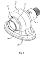
- ist eine perspektivische Darstellung der Anordnung aus Sensor und Befestigungsvorrichtung gemäß
Fig. 2 . - Gemäß
Fig. 1 und2 weist eine Vorrichtung zur Befestigung eines Sensors an einem lediglich schematisch dargestellten Trägerbauteil 11 ein elastisches Element 13 auf, in welchem eine zylindrische Durchführung 15 zur Aufnahme eines zu befestigenden Sensors 17 (Fig. 2 ) ausgebildet ist. Bei dem Sensor 17 kann es sich beispielsweise um einen gewindelosen Rundsensor handeln. Das elastische Element 13 ist in einem halbschalenartigen Gehäuse 19 aufgenommen. Das Gehäuse 19 umhüllt das elastische Element 13 im Wesentlichen vollständig, wobei jedoch an einer unteren Befestigungsseite 20 des Gehäuses 19 eine Öffnung 21 vorgesehen ist, aus welcher ein Überstandsabschnitt 23 des elastischen Elements 13 herausragt. Wie insbesondere ausFig. 2 hervorgeht, definiert das Gehäuse 19 weiterhin zwei mit der Durchführung 15 des elastischen Elements 13 fluchtende Durchführungsöffnungen 31 für den zu befestigenden Sensor 17, wobei das elastische Element 13 im Bereich der Durchführungsöffnungen 31 jeweils eine zwischen der Außenwand des Sensors 17 und dem Gehäuse 19 wirksame Dichtlippe 27 bildet. - Wie
Fig. 1 zu entnehmen ist, weist der Überstandsabschnitt 23 des elastischen Elements 13 eine konkav geformte Stirnfläche 25 auf. Die Beschaffenheit des elastischen Elements 13 kann hinsichtlich der mechanischen Festigkeit und der Beständigkeit an die jeweilige Anwendung angepasst sein. Beispielsweise kann das elastische Element 13 aus einem Elastomer und vorzugsweise aus NBR, Silikon oder Teflon gefertigt sein. Insbesondere kann das elastische Element 13 als Spritzteil hergestellt sein. - Das Gehäuse 19 kann als Metallspritzguss, insbesondere MIM, Feinguss oder als mechanisch bearbeitetes Teil hergestellt sein. Das Material des Gehäuses 19 kann an die jeweilige Anwendung angepasst sein. Beispielsweise kann das Gehäuse 19 aus einer V4A-Legierung bestehen.
- Die Verbindung des elastischen Elements 13 mit dem Gehäuse 19 kann durch Fügen der beiden Teile aneinander erfolgen oder vorzugsweise dadurch, dass das elastische Element 13 von dem Gehäuse 19 umspritzt wird. Eine derartige durch Umspritzen hergestellte Anordnung ist besonders beständig gegen die bei Reinigung z.B. mittels Hochdruckreiniger auftretenden hohen mechanischen Belastungen.
- An der Öffnung 21 ist ein Dichtelement 29 aus elastischem Material vorgesehen, welches die Öffnung 21 vollständig umrandet. Das Dichtelement 29 kann durch einen Abschnitt des elastischen Elements 13 selbst gebildet sein oder als separates Bauteil an dem Gehäuse 19 angebracht sein. Insbesondere kann das Dichtelement 29 eine doppelte Dichtlippe aufweisen.
- Zwei zur Befestigungsseite 20 hin offene Gewindesacklöcher 33 des Gehäuses 19 dienen der Aufnahme von nicht dargestellten Schrauben, welche zur Befestigung des Gehäuses 19 an dem Trägerbauteil 11 verwendet werden.
- Zur Befestigung des Sensors 17 an dem Trägerbauteil 11 wird der Sensor 17 zunächst durch die Durchführungsöffnungen 31 des Gehäuses 19 sowie die Durchführung 15 des elastischen Elements 13 gesteckt. Anschließend wird das Gehäuse 19 mittels geeigneter Befestigungsschrauben in Richtung einer ebenen Andrückfläche 35 des Trägerbauteils 11 gezogen. Dabei wird der vorstehende Überstandsabschnitt 23 zusammengedrückt, wie in
Fig. 1 durch Pfeile verdeutlich ist. Der dadurch erzeugte Druck verteilt sich im elastischen Element 13. Da dieses von der Innenwand des Gehäuses 19 sowie von der Andrückfläche 35 im Wesentlichen vollständig umschlossen ist, führt der Druck letztendlich zu einer Verringerung des Querschnitts der Durchführung 15, was eine Verankerung des Sensors 17 in der Durchführung 15 bewirkt. Gleichzeitig werden die Dichtlippen 27 fest an die Außenwand des Sensors 17 gedrückt, so dass sich ein zuverlässig dichtender Übergang zwischen dem Sensor 17 und dem Gehäuse 19 ergibt. Nach Abschluss des Befestigungsvorgangs ziehen die Schrauben das Gehäuse 19 mit dem Dichtelement 29 voraus fest gegen die Andrückfläche 35, so dass sich auch ein zuverlässig dichtender Übergang zwischen dem Trägerbauteil 11 und dem Gehäuse 19 ergibt. - Die Gesamtanordnung nach Abschluss des Befestigungsvorgangs ist in
Fig. 3 perspektivisch dargestellt. Wie ausFig. 3 hervorgeht, liegen im Wesentlichen glatte und abgerundete Oberflächen vor, welche besonders leicht zu reinigen sind, Schlitze, Hohlräume, Ecken, Kanten, Gewindeabschnitte und sonstige Unregelmäßigkeiten, in welchen sich potentiell Reinigungsmittelrückstände und andere Ablagerungen sammeln können, sind nicht vorhanden. Durch ein einfaches Festschrauben werden sowohl der Sensor 17 in dem elastischen Element 13 als auch das Gehäuse 19 an dem Trägerbauteil 11 befestigt. Ein Klebevorgang ist nicht erforderlich. Da es ferner in der Regel auf die Drehstellung des Sensors 17 in der Durchführung 15 nicht ankommt, ergibt sich ein besonders einfacher Montagevorgang. - Insgesamt ermöglicht die Erfindung eine einfache und zuverlässige Befestigung von Sensoren in hygienisch sensiblen Bereichen.
-
- 11
- Trägerbauteil
- 13
- elastisches Element
- 15
- Durchführung
- 17
- Sensor
- 19
- Gehäuse
- 20
- Befestigungsseite
- 21
- Öffnung
- 23
- Überstandsabschnitt
- 25
- Stirnfläche
- 27
- Dichtlippe
- 29
- Dichtelement
- 31
- Durchführungsöffnung
- 33
- Gewindesackloch
- 35
- Andrückfläche
Claims (7)
- Vorrichtung zur Befestigung eines Sensors (17) an einem Trägerbauteil (11), mit
einem elastischen Element (13), das eine Aussparung (15) zur Aufnahme zumindest eines Teils des zu befestigenden Sensors (17) aufweist, und
einem das elastische Element (13) aufnehmenden Gehäuse (19), wobei Befestigungsmittel zum Befestigen des Gehäuses (19) an dem Trägerbauteil (11) vorgesehen sind, die dazu ausgebildet sind, zusätzlich das Gehäuse (19) derart in Richtung einer Andrückfläche (35) des Trägerbauteils (11) vorzuspannen, dass ein im Bereich der Andrückfläche (35) aus einer Öffnung (21) des Gehäuses (19) ragender Überstandsabschnitt (23) des elastischen Elements (13) unter Verringerung des Querschnitts der Aussparung (15) zusammengedrückt wird. - Vorrichtung nach Anspruch 1,
dadurch gekennzeichnet, dass
an der Öffnung (21) des Gehäuses (19) ein Dichtelement (29) aus elastischem Material vorgesehen ist. - Vorrichtung nach Anspruch 1 oder 2,
dadurchgekennzeichnet,dass
der Überstandsabschnitt (23) des elastischen Elements (13) eine konkave Stirnfläche aufweist. - Vorrichtung nach zumindest einem der vorstehenden Ansprüche,
dadurchgekennzeichnet, dass
die Befestigungsmittel Schrauben umfassen, welche in das Gehäuse (19) und das Trägerbauteil (11) eingreifen. - Vorrichtung nach zumindest einem der vorstehenden Ansprüche,
dadurchgekennzeichnet, dass
das Gehäuse (19) eine Durchführung (31) für den Sensor (17) definiert, wobei das elastische Element (13) im Bereich der Durchführung (31) eine zwischen der Außenwand des zu befestigenden Sensors (17) und dem Gehäuse (19) wirksame Dichtlippe (27) bildet. - Vorrichtung nach zumindest einem der vorstehenden Ansprüche,
dadurchgekennzeichnet, dass
das Gehäuse (19) halbschalenartig ausgebildet ist und konvexe Außenflächen aufweist. - Vorrichtung nach zumindest einem der vorstehenden Ansprüche,
dadurchgekennzeichnet, dass
das Gehäuse (19) als Spritzgussteil ausgeführt ist, wobei das elastische Element (13) von dem Gehäuse (19) umspritzt ist.
Applications Claiming Priority (1)
| Application Number | Priority Date | Filing Date | Title |
|---|---|---|---|
| DE202010014864U DE202010014864U1 (de) | 2010-10-28 | 2010-10-28 | Vorrichtung zur Befestigung eines Sensors |
Publications (3)
| Publication Number | Publication Date |
|---|---|
| EP2447679A2 true EP2447679A2 (de) | 2012-05-02 |
| EP2447679A3 EP2447679A3 (de) | 2013-05-01 |
| EP2447679B1 EP2447679B1 (de) | 2014-01-15 |
Family
ID=43430563
Family Applications (1)
| Application Number | Title | Priority Date | Filing Date |
|---|---|---|---|
| EP20110007119 Active EP2447679B1 (de) | 2010-10-28 | 2011-09-01 | Vorrichtung zur Befestigung eines Sensors |
Country Status (2)
| Country | Link |
|---|---|
| EP (1) | EP2447679B1 (de) |
| DE (1) | DE202010014864U1 (de) |
Families Citing this family (2)
| Publication number | Priority date | Publication date | Assignee | Title |
|---|---|---|---|---|
| DE102016008655B4 (de) * | 2016-07-15 | 2024-01-25 | Sartorius Stedim Biotech Gmbh | Anlage für biotechnologische Anwendungen mit Träger zur Lagerung von Komponenten |
| DE102021133449A1 (de) | 2021-12-16 | 2023-06-22 | Valeo Schalter Und Sensoren Gmbh | Erstes Gehäuseteil für ein Gehäuse für eine Vorrichtung für ein Fahrzeug, Gehäuse, Vorrichtung, Fahrzeug mit wenigstens einer Vorrichtung und Verfahren zur Montage einer Vorrichtung |
Citations (1)
| Publication number | Priority date | Publication date | Assignee | Title |
|---|---|---|---|---|
| DE4041090C2 (de) | 1990-12-21 | 2001-01-04 | Festo Ag & Co | Befestigungsvorrichtung für Sensoren |
Family Cites Families (2)
| Publication number | Priority date | Publication date | Assignee | Title |
|---|---|---|---|---|
| DE10003941A1 (de) * | 2000-01-29 | 2001-08-09 | Endress Hauser Gmbh Co | Füllstandsmeßgerät |
| DE102007056340A1 (de) * | 2007-11-22 | 2009-05-28 | Wabco Gmbh | Klemmbuchse für einen Sensor |
-
2010
- 2010-10-28 DE DE202010014864U patent/DE202010014864U1/de not_active Expired - Lifetime
-
2011
- 2011-09-01 EP EP20110007119 patent/EP2447679B1/de active Active
Patent Citations (1)
| Publication number | Priority date | Publication date | Assignee | Title |
|---|---|---|---|---|
| DE4041090C2 (de) | 1990-12-21 | 2001-01-04 | Festo Ag & Co | Befestigungsvorrichtung für Sensoren |
Also Published As
| Publication number | Publication date |
|---|---|
| EP2447679B1 (de) | 2014-01-15 |
| DE202010014864U1 (de) | 2011-01-05 |
| EP2447679A3 (de) | 2013-05-01 |
Similar Documents
| Publication | Publication Date | Title |
|---|---|---|
| EP1784318B1 (de) | Einbauvorrichtung für einen sensor | |
| WO2020011680A1 (de) | Batteriegehäuse | |
| DE102010051372A1 (de) | Verbindungselement mit integrierter Schnappverbindung | |
| EP2447679B1 (de) | Vorrichtung zur Befestigung eines Sensors | |
| EP2184822B1 (de) | Tauchmotor | |
| EP2852015B1 (de) | Kabeldurchführungseinrichtung | |
| DE102004001788A1 (de) | Anordnung zur axial verstellbaren Halterung eines berührungslos arbeitenden Sensors | |
| EP1857687B1 (de) | Drehfeste lösbare mechanische Verbindung zwischen einem Funktionsteil und einem Anschlussteil | |
| EP3441625A1 (de) | Montageelement mit druckbegrenzung | |
| EP3293496B1 (de) | Längenmesseinrichtung und verfahren zu deren montage | |
| DE102011085128A1 (de) | Vorrichtung zur Bestimmung und/oder Überwachung mindestens einer Prozessgröße | |
| EP1780854A1 (de) | Kabel- oder Schlauchverschraubung | |
| DE2221267B2 (de) | Spreizduebel | |
| WO2011128007A1 (de) | Halterung für ein zylindrisches objekt in einer platte | |
| EP4534858A1 (de) | Schnappverbindung, kraftfahrzeugstruktur sowie kraftfahrzeug | |
| DE102017123559B4 (de) | Vorrichtung zur Befestigung eines Zylindersensors an einem Hygienezylinder | |
| DE10257818A1 (de) | Stutzen für eine Behälterwand | |
| DE102004048436A1 (de) | Steckhülse zur Befestigung eines Bauteils in einer Bohrung | |
| EP2119919A2 (de) | Befestigungsanordnung | |
| DE19953834A1 (de) | Befestigungseinrichtung | |
| EP2679272A1 (de) | Trokarvorrichtung | |
| DE102007021210B3 (de) | Fenster-, Tür- oder Torbeschlag | |
| EP3859923B1 (de) | Erdleiterdurchführung | |
| DE19835788B4 (de) | Montagevorrichtung | |
| DE20220837U1 (de) | Rohrverschraubung |
Legal Events
| Date | Code | Title | Description |
|---|---|---|---|
| PUAI | Public reference made under article 153(3) epc to a published international application that has entered the european phase |
Free format text: ORIGINAL CODE: 0009012 |
|
| AK | Designated contracting states |
Kind code of ref document: A2 Designated state(s): AL AT BE BG CH CY CZ DE DK EE ES FI FR GB GR HR HU IE IS IT LI LT LU LV MC MK MT NL NO PL PT RO RS SE SI SK SM TR |
|
| AX | Request for extension of the european patent |
Extension state: BA ME |
|
| PUAL | Search report despatched |
Free format text: ORIGINAL CODE: 0009013 |
|
| AK | Designated contracting states |
Kind code of ref document: A3 Designated state(s): AL AT BE BG CH CY CZ DE DK EE ES FI FR GB GR HR HU IE IS IT LI LT LU LV MC MK MT NL NO PL PT RO RS SE SI SK SM TR |
|
| AX | Request for extension of the european patent |
Extension state: BA ME |
|
| RIC1 | Information provided on ipc code assigned before grant |
Ipc: F15B 15/28 20060101ALI20130325BHEP Ipc: G01D 11/30 20060101AFI20130325BHEP |
|
| 17P | Request for examination filed |
Effective date: 20130429 |
|
| GRAP | Despatch of communication of intention to grant a patent |
Free format text: ORIGINAL CODE: EPIDOSNIGR1 |
|
| RIC1 | Information provided on ipc code assigned before grant |
Ipc: F15B 15/28 20060101ALI20130625BHEP Ipc: G01D 11/30 20060101AFI20130625BHEP |
|
| INTG | Intention to grant announced |
Effective date: 20130726 |
|
| GRAS | Grant fee paid |
Free format text: ORIGINAL CODE: EPIDOSNIGR3 |
|
| GRAA | (expected) grant |
Free format text: ORIGINAL CODE: 0009210 |
|
| AK | Designated contracting states |
Kind code of ref document: B1 Designated state(s): AL AT BE BG CH CY CZ DE DK EE ES FI FR GB GR HR HU IE IS IT LI LT LU LV MC MK MT NL NO PL PT RO RS SE SI SK SM TR |
|
| REG | Reference to a national code |
Ref country code: GB Ref legal event code: FG4D Free format text: NOT ENGLISH Ref country code: CH Ref legal event code: EP |
|
| REG | Reference to a national code |
Ref country code: AT Ref legal event code: REF Ref document number: 650038 Country of ref document: AT Kind code of ref document: T Effective date: 20140215 |
|
| REG | Reference to a national code |
Ref country code: IE Ref legal event code: FG4D Free format text: LANGUAGE OF EP DOCUMENT: GERMAN |
|
| REG | Reference to a national code |
Ref country code: DE Ref legal event code: R096 Ref document number: 502011002025 Country of ref document: DE Effective date: 20140306 |
|
| REG | Reference to a national code |
Ref country code: NL Ref legal event code: VDEP Effective date: 20140115 |
|
| REG | Reference to a national code |
Ref country code: LT Ref legal event code: MG4D |
|
| PG25 | Lapsed in a contracting state [announced via postgrant information from national office to epo] |
Ref country code: NO Free format text: LAPSE BECAUSE OF FAILURE TO SUBMIT A TRANSLATION OF THE DESCRIPTION OR TO PAY THE FEE WITHIN THE PRESCRIBED TIME-LIMIT Effective date: 20140415 Ref country code: LT Free format text: LAPSE BECAUSE OF FAILURE TO SUBMIT A TRANSLATION OF THE DESCRIPTION OR TO PAY THE FEE WITHIN THE PRESCRIBED TIME-LIMIT Effective date: 20140115 Ref country code: IS Free format text: LAPSE BECAUSE OF FAILURE TO SUBMIT A TRANSLATION OF THE DESCRIPTION OR TO PAY THE FEE WITHIN THE PRESCRIBED TIME-LIMIT Effective date: 20140515 |
|
| PG25 | Lapsed in a contracting state [announced via postgrant information from national office to epo] |
Ref country code: NL Free format text: LAPSE BECAUSE OF FAILURE TO SUBMIT A TRANSLATION OF THE DESCRIPTION OR TO PAY THE FEE WITHIN THE PRESCRIBED TIME-LIMIT Effective date: 20140115 Ref country code: FI Free format text: LAPSE BECAUSE OF FAILURE TO SUBMIT A TRANSLATION OF THE DESCRIPTION OR TO PAY THE FEE WITHIN THE PRESCRIBED TIME-LIMIT Effective date: 20140115 Ref country code: ES Free format text: LAPSE BECAUSE OF FAILURE TO SUBMIT A TRANSLATION OF THE DESCRIPTION OR TO PAY THE FEE WITHIN THE PRESCRIBED TIME-LIMIT Effective date: 20140115 Ref country code: CY Free format text: LAPSE BECAUSE OF FAILURE TO SUBMIT A TRANSLATION OF THE DESCRIPTION OR TO PAY THE FEE WITHIN THE PRESCRIBED TIME-LIMIT Effective date: 20140115 Ref country code: PT Free format text: LAPSE BECAUSE OF FAILURE TO SUBMIT A TRANSLATION OF THE DESCRIPTION OR TO PAY THE FEE WITHIN THE PRESCRIBED TIME-LIMIT Effective date: 20140515 Ref country code: SE Free format text: LAPSE BECAUSE OF FAILURE TO SUBMIT A TRANSLATION OF THE DESCRIPTION OR TO PAY THE FEE WITHIN THE PRESCRIBED TIME-LIMIT Effective date: 20140115 |
|
| PG25 | Lapsed in a contracting state [announced via postgrant information from national office to epo] |
Ref country code: LV Free format text: LAPSE BECAUSE OF FAILURE TO SUBMIT A TRANSLATION OF THE DESCRIPTION OR TO PAY THE FEE WITHIN THE PRESCRIBED TIME-LIMIT Effective date: 20140115 Ref country code: HR Free format text: LAPSE BECAUSE OF FAILURE TO SUBMIT A TRANSLATION OF THE DESCRIPTION OR TO PAY THE FEE WITHIN THE PRESCRIBED TIME-LIMIT Effective date: 20140115 Ref country code: RS Free format text: LAPSE BECAUSE OF FAILURE TO SUBMIT A TRANSLATION OF THE DESCRIPTION OR TO PAY THE FEE WITHIN THE PRESCRIBED TIME-LIMIT Effective date: 20140115 |
|
| REG | Reference to a national code |
Ref country code: DE Ref legal event code: R097 Ref document number: 502011002025 Country of ref document: DE |
|
| PG25 | Lapsed in a contracting state [announced via postgrant information from national office to epo] |
Ref country code: EE Free format text: LAPSE BECAUSE OF FAILURE TO SUBMIT A TRANSLATION OF THE DESCRIPTION OR TO PAY THE FEE WITHIN THE PRESCRIBED TIME-LIMIT Effective date: 20140115 Ref country code: DK Free format text: LAPSE BECAUSE OF FAILURE TO SUBMIT A TRANSLATION OF THE DESCRIPTION OR TO PAY THE FEE WITHIN THE PRESCRIBED TIME-LIMIT Effective date: 20140115 Ref country code: RO Free format text: LAPSE BECAUSE OF FAILURE TO SUBMIT A TRANSLATION OF THE DESCRIPTION OR TO PAY THE FEE WITHIN THE PRESCRIBED TIME-LIMIT Effective date: 20140115 Ref country code: CZ Free format text: LAPSE BECAUSE OF FAILURE TO SUBMIT A TRANSLATION OF THE DESCRIPTION OR TO PAY THE FEE WITHIN THE PRESCRIBED TIME-LIMIT Effective date: 20140115 |
|
| PLBE | No opposition filed within time limit |
Free format text: ORIGINAL CODE: 0009261 |
|
| STAA | Information on the status of an ep patent application or granted ep patent |
Free format text: STATUS: NO OPPOSITION FILED WITHIN TIME LIMIT |
|
| PG25 | Lapsed in a contracting state [announced via postgrant information from national office to epo] |
Ref country code: SK Free format text: LAPSE BECAUSE OF FAILURE TO SUBMIT A TRANSLATION OF THE DESCRIPTION OR TO PAY THE FEE WITHIN THE PRESCRIBED TIME-LIMIT Effective date: 20140115 Ref country code: PL Free format text: LAPSE BECAUSE OF FAILURE TO SUBMIT A TRANSLATION OF THE DESCRIPTION OR TO PAY THE FEE WITHIN THE PRESCRIBED TIME-LIMIT Effective date: 20140115 |
|
| 26N | No opposition filed |
Effective date: 20141016 |
|
| REG | Reference to a national code |
Ref country code: DE Ref legal event code: R097 Ref document number: 502011002025 Country of ref document: DE Effective date: 20141016 |
|
| PG25 | Lapsed in a contracting state [announced via postgrant information from national office to epo] |
Ref country code: MC Free format text: LAPSE BECAUSE OF FAILURE TO SUBMIT A TRANSLATION OF THE DESCRIPTION OR TO PAY THE FEE WITHIN THE PRESCRIBED TIME-LIMIT Effective date: 20140115 Ref country code: LU Free format text: LAPSE BECAUSE OF FAILURE TO SUBMIT A TRANSLATION OF THE DESCRIPTION OR TO PAY THE FEE WITHIN THE PRESCRIBED TIME-LIMIT Effective date: 20140901 |
|
| PG25 | Lapsed in a contracting state [announced via postgrant information from national office to epo] |
Ref country code: SI Free format text: LAPSE BECAUSE OF FAILURE TO SUBMIT A TRANSLATION OF THE DESCRIPTION OR TO PAY THE FEE WITHIN THE PRESCRIBED TIME-LIMIT Effective date: 20140115 |
|
| REG | Reference to a national code |
Ref country code: IE Ref legal event code: MM4A |
|
| PG25 | Lapsed in a contracting state [announced via postgrant information from national office to epo] |
Ref country code: BE Free format text: LAPSE BECAUSE OF NON-PAYMENT OF DUE FEES Effective date: 20140930 |
|
| PG25 | Lapsed in a contracting state [announced via postgrant information from national office to epo] |
Ref country code: IE Free format text: LAPSE BECAUSE OF NON-PAYMENT OF DUE FEES Effective date: 20140901 |
|
| PG25 | Lapsed in a contracting state [announced via postgrant information from national office to epo] |
Ref country code: SM Free format text: LAPSE BECAUSE OF FAILURE TO SUBMIT A TRANSLATION OF THE DESCRIPTION OR TO PAY THE FEE WITHIN THE PRESCRIBED TIME-LIMIT Effective date: 20140115 |
|
| GBPC | Gb: european patent ceased through non-payment of renewal fee |
Effective date: 20150901 |
|
| PG25 | Lapsed in a contracting state [announced via postgrant information from national office to epo] |
Ref country code: MT Free format text: LAPSE BECAUSE OF FAILURE TO SUBMIT A TRANSLATION OF THE DESCRIPTION OR TO PAY THE FEE WITHIN THE PRESCRIBED TIME-LIMIT Effective date: 20140115 Ref country code: GR Free format text: LAPSE BECAUSE OF FAILURE TO SUBMIT A TRANSLATION OF THE DESCRIPTION OR TO PAY THE FEE WITHIN THE PRESCRIBED TIME-LIMIT Effective date: 20140416 Ref country code: BG Free format text: LAPSE BECAUSE OF FAILURE TO SUBMIT A TRANSLATION OF THE DESCRIPTION OR TO PAY THE FEE WITHIN THE PRESCRIBED TIME-LIMIT Effective date: 20140115 |
|
| PG25 | Lapsed in a contracting state [announced via postgrant information from national office to epo] |
Ref country code: HU Free format text: LAPSE BECAUSE OF FAILURE TO SUBMIT A TRANSLATION OF THE DESCRIPTION OR TO PAY THE FEE WITHIN THE PRESCRIBED TIME-LIMIT; INVALID AB INITIO Effective date: 20110901 Ref country code: GB Free format text: LAPSE BECAUSE OF NON-PAYMENT OF DUE FEES Effective date: 20150901 Ref country code: TR Free format text: LAPSE BECAUSE OF FAILURE TO SUBMIT A TRANSLATION OF THE DESCRIPTION OR TO PAY THE FEE WITHIN THE PRESCRIBED TIME-LIMIT Effective date: 20140115 |
|
| REG | Reference to a national code |
Ref country code: FR Ref legal event code: PLFP Year of fee payment: 6 |
|
| REG | Reference to a national code |
Ref country code: FR Ref legal event code: PLFP Year of fee payment: 7 |
|
| PG25 | Lapsed in a contracting state [announced via postgrant information from national office to epo] |
Ref country code: MK Free format text: LAPSE BECAUSE OF FAILURE TO SUBMIT A TRANSLATION OF THE DESCRIPTION OR TO PAY THE FEE WITHIN THE PRESCRIBED TIME-LIMIT Effective date: 20140115 |
|
| REG | Reference to a national code |
Ref country code: FR Ref legal event code: PLFP Year of fee payment: 8 |
|
| PG25 | Lapsed in a contracting state [announced via postgrant information from national office to epo] |
Ref country code: AL Free format text: LAPSE BECAUSE OF FAILURE TO SUBMIT A TRANSLATION OF THE DESCRIPTION OR TO PAY THE FEE WITHIN THE PRESCRIBED TIME-LIMIT Effective date: 20140115 |
|
| PGFP | Annual fee paid to national office [announced via postgrant information from national office to epo] |
Ref country code: IT Payment date: 20210930 Year of fee payment: 11 Ref country code: CH Payment date: 20210923 Year of fee payment: 11 Ref country code: AT Payment date: 20210917 Year of fee payment: 11 Ref country code: FR Payment date: 20210927 Year of fee payment: 11 |
|
| REG | Reference to a national code |
Ref country code: CH Ref legal event code: PL |
|
| REG | Reference to a national code |
Ref country code: AT Ref legal event code: MM01 Ref document number: 650038 Country of ref document: AT Kind code of ref document: T Effective date: 20220901 |
|
| PG25 | Lapsed in a contracting state [announced via postgrant information from national office to epo] |
Ref country code: LI Free format text: LAPSE BECAUSE OF NON-PAYMENT OF DUE FEES Effective date: 20220930 Ref country code: FR Free format text: LAPSE BECAUSE OF NON-PAYMENT OF DUE FEES Effective date: 20220930 Ref country code: CH Free format text: LAPSE BECAUSE OF NON-PAYMENT OF DUE FEES Effective date: 20220930 Ref country code: AT Free format text: LAPSE BECAUSE OF NON-PAYMENT OF DUE FEES Effective date: 20220901 |
|
| PG25 | Lapsed in a contracting state [announced via postgrant information from national office to epo] |
Ref country code: IT Free format text: LAPSE BECAUSE OF NON-PAYMENT OF DUE FEES Effective date: 20220901 |
|
| PGFP | Annual fee paid to national office [announced via postgrant information from national office to epo] |
Ref country code: DE Payment date: 20240919 Year of fee payment: 14 |