EP2447505A2 - Inlet air cooling and moisture removal methods and devices in advanced adiabatic compressed air energy storage systems - Google Patents
Inlet air cooling and moisture removal methods and devices in advanced adiabatic compressed air energy storage systems Download PDFInfo
- Publication number
- EP2447505A2 EP2447505A2 EP11186992A EP11186992A EP2447505A2 EP 2447505 A2 EP2447505 A2 EP 2447505A2 EP 11186992 A EP11186992 A EP 11186992A EP 11186992 A EP11186992 A EP 11186992A EP 2447505 A2 EP2447505 A2 EP 2447505A2
- Authority
- EP
- European Patent Office
- Prior art keywords
- air
- compressed
- compressor
- air flow
- cooled
- Prior art date
- Legal status (The legal status is an assumption and is not a legal conclusion. Google has not performed a legal analysis and makes no representation as to the accuracy of the status listed.)
- Granted
Links
Images


Classifications
-
- F—MECHANICAL ENGINEERING; LIGHTING; HEATING; WEAPONS; BLASTING
- F02—COMBUSTION ENGINES; HOT-GAS OR COMBUSTION-PRODUCT ENGINE PLANTS
- F02C—GAS-TURBINE PLANTS; AIR INTAKES FOR JET-PROPULSION PLANTS; CONTROLLING FUEL SUPPLY IN AIR-BREATHING JET-PROPULSION PLANTS
- F02C6/00—Plural gas-turbine plants; Combinations of gas-turbine plants with other apparatus; Adaptations of gas-turbine plants for special use
- F02C6/14—Gas-turbine plants having means for storing energy, e.g. for meeting peak loads
- F02C6/16—Gas-turbine plants having means for storing energy, e.g. for meeting peak loads for storing compressed air
-
- F—MECHANICAL ENGINEERING; LIGHTING; HEATING; WEAPONS; BLASTING
- F02—COMBUSTION ENGINES; HOT-GAS OR COMBUSTION-PRODUCT ENGINE PLANTS
- F02C—GAS-TURBINE PLANTS; AIR INTAKES FOR JET-PROPULSION PLANTS; CONTROLLING FUEL SUPPLY IN AIR-BREATHING JET-PROPULSION PLANTS
- F02C7/00—Features, components parts, details or accessories, not provided for in, or of interest apart form groups F02C1/00 - F02C6/00; Air intakes for jet-propulsion plants
- F02C7/12—Cooling of plants
- F02C7/14—Cooling of plants of fluids in the plant, e.g. lubricant or fuel
- F02C7/141—Cooling of plants of fluids in the plant, e.g. lubricant or fuel of working fluid
-
- Y—GENERAL TAGGING OF NEW TECHNOLOGICAL DEVELOPMENTS; GENERAL TAGGING OF CROSS-SECTIONAL TECHNOLOGIES SPANNING OVER SEVERAL SECTIONS OF THE IPC; TECHNICAL SUBJECTS COVERED BY FORMER USPC CROSS-REFERENCE ART COLLECTIONS [XRACs] AND DIGESTS
- Y02—TECHNOLOGIES OR APPLICATIONS FOR MITIGATION OR ADAPTATION AGAINST CLIMATE CHANGE
- Y02E—REDUCTION OF GREENHOUSE GAS [GHG] EMISSIONS, RELATED TO ENERGY GENERATION, TRANSMISSION OR DISTRIBUTION
- Y02E60/00—Enabling technologies; Technologies with a potential or indirect contribution to GHG emissions mitigation
- Y02E60/16—Mechanical energy storage, e.g. flywheels or pressurised fluids
Definitions
- the embodiments of the subject matter disclosed herein generally relate to power generation systems and more specifically to advanced adiabatic compressed air energy storage systems.
- AA-CAES Advanced Adiabatic Compressed Air Energy Storage
- Figure 1 The power generation system 2 is now generally described by following the path of the air flow.
- air is taken into an axial compressor 4 and compressed during which the air is put under pressure and undergoes an increase in temperature.
- This air is exhausted in step 3b, and undergoes cooling at the Intercooler 6 to be cooled to the desired temperature for further compression.
- the air flow is then entered in step 3c to a first radial compressor 8.
- the air is then compressed by the first radial compressor 8, exits the first radial compressor 8 and in step 3d enters a second radial compressor 10 for further compression.
- the air flow then goes, in step 3e, from the second radial compressor 10 to an energy storage unit, e.g., a Thermal Energy Store 12.
- the hot compressed air from the second radial compressor 10 is then cooled by the Thermal Energy Store 12.
- the heat energy is stored in the Thermal Energy Store 12 for future use and any water that is generated by the cooling process is drained off.
- the cooled compressed air is then sent to a Safety Cooler 14 in step 3f, where the air is further cooled prior to being sent in step 3g to a storage facility, e.g., cavern 16.
- This storage of the compressed air in the cavern 16 and the storage of the energy in the Thermal Energy Store 12 typically occurs during non-peak demand operation of the power generation system 2.
- energy output can be increased by releasing the stored compressed air back into the system to drive an expander 18, e.g., a turbine.
- the cavern 16 releases some of the stored compressed air, in step 3h, to the Thermal Energy Store 12 for heating. Heat energy is transferred from the Thermal Energy Store 12 to the compressed air and the heated compressed air flows to a particle filter 20 in step 3i. The heated compressed air then flows, in step 3j, to an expansion section of turbine 18. During expansion the air cools and undergoes a pressure drop while producing the work which drives the shaft 26 which in turn spins a portion of a generator 30 for power generation. After expansion the air flows from the turbine 18 to an air outlet 22 in step 3k, typically for release to atmosphere.
- Power generation system 2 can also include a shaft 24 for the compressors, a gear box 28 and a motor 32.
- the system includes: an air handling unit configured to receive air, to cool the air and to remove moisture from the air; the first compressor fluidly connected to the air handling unit and configured to receive the air from the air handling unit and to exhaust a first compressed, heated air flow; a vapor absorption chiller connected to the first compressor and configured to transfer heat energy between a plurality of mediums and to cool the first compressed, heated air flow; a second compressor connected to the vapor absorption chiller and configured to receive the cooled first compressed, heated air flow and to exhaust a second compressed, heated air flow; an energy storage unit connected to the second compressor and configured to store heat energy from the second compressed, heated air flow; and a storage facility connected to the energy storage unit and configured to store a cooled, compressed air received from the energy storage unit and to selectively release the cooled, compressed air back into the power generation system.
- a system for cooling air in a power generation system includes: an air handling unit configured to receive air, to cool the air and to remove moisture from the air; a first compressor fluidly connected to the air handling unit and configured to receive the air from the air handling unit and to exhaust a first compressed, heated air flow; a vapor absorption chiller connected to the first compressor and configured to transfer heat energy between a plurality of mediums and to cool the first compressed, heated air flow; and a second compressor connected to the vapor absorption chiller and configured to receive the cooled first compressed, heated air flow and to exhaust a second compressed, heated air flow.
- the method includes: receiving air at an air handling unit; cooling the air at the air handling unit; removing moisture from the air at the air handling unit; compressing air by a first compressor; exhausting a first compressed, heated air flow from the first compressor; transferring heat energy between a plurality of mediums at an vapor absorption chiller; cooling the first compressed, heated air flow at the vapor absorption chiller; compressing the cooled first compressed, heated air flow; and exhausting a second compressed, heated air flow.
- Figure 1 depicts a power generation system and an Advanced Adiabatic Compressed Air Energy Storage (AA-CAES) system;
- AA-CAES Advanced Adiabatic Compressed Air Energy Storage
- Figure 2 illustrates a power generation system and an efficient AA-CAES system according to exemplary embodiments
- Figure 3 shows the system of Figure 2 with illustrative values according to exemplary embodiments
- Figure 4 illustrates a power generation system and an another efficient AA-CAES system according to exemplary embodiments
- Figure 5 shows the system of Figure 4 with illustrative values according to exemplary embodiments
- Figure 6 illustrates an air cooling system in a power generation system according to exemplary embodiments
- Figure 7 illustrates an air handler and a vapor absorption chiller according to exemplary embodiments
- Figure 8 shows the system of Figure 6 with illustrative values according to exemplary embodiments
- Figures 9 and 10 are flowcharts showing a method for capturing heat energy in a power generation system according to exemplary embodiments.
- Figure 11 is a flowchart showing a method for cooling air in a power generation system according to exemplary embodiments.
- exemplary embodiments described herein provide systems and methods for improving efficiency in power generation systems.
- heat energy typically lost between compressors in a Compressed Air Energy Storage (CAES) system can be recovered for use in a modified adiabatic CAES (AA-CAES) system, an example of which is shown in Figure 2 .
- CAES Compressed Air Energy Storage
- AA-CAES modified adiabatic CAES
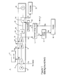
- Figure 2 shows a power generation system 202 which includes a modified AA-CAES system which captures and stores the heat energy, which is typically lost between an axial compressor 204 and a radial compressor 206, for use during peak or near peak load conditions. By capturing this heat energy there can be approximately an 8-10 percent improvement in overall operating efficiency of the power generation system 202 when compared with the system 2 shown in Figure 1 .
- This system will now be described by generally following the flow of air in the system starting with an air intake to the axial compressor 204. Initially in step 5a, air is taken into an axial compressor 204 and compressed during which the air is put under pressure and undergoes an increase in temperature.
- This air is exhausted from the axial compressor 204 in step 5b, and undergoes heat exchange in a heat exchanger, e.g., Intercooler 208, with oil which is in its own closed loop system.
- a heat exchanger e.g., Intercooler 208
- the cooled air flow then enters, in step 5c, the first radial compressor 206.
- the air is then compressed by the first radial compressor 206, exits the first radial compressor 206 and in step 5d enters a second radial compressor 210 for further compression.
- the power generation system 202 can include an axial compressor 204 and a single radial compressor 206.
- the air flow then goes in step 5e from the second radial compressor 210 to an energy storage unit, e.g., a Thermal Energy Store 212.
- the hot compressed air from the second radial compressor 210 is then cooled by the Thermal Energy Store 212.
- the heat energy is stored in the Thermal Energy Store 212 for future use and any water that is generated by the cooling process is drained off.
- the cooled compressed air is then sent to a Safety Cooler 214 in step 5f, where the air is further cooled prior to being sent in step 5g to a storage facility, e.g., cavern 216.
- This storage of the compressed air in the cavern 216 and the storage of the energy in the Thermal Energy Store 212 typically occurs during non-peak demand operation of the power generation system 202.
- energy output can be increased by releasing the stored compressed air back into the system to drive an expander 218, e.g., a turbine.
- the cavern 216 releases some of the stored compressed air in step 5h which undergoes preheating in an insulated hot oil tank 220.
- the released compressed air then flows to the Thermal Energy Store 212 for heating in step 5i.
- Heat energy is transferred from the Thermal Energy Store 212 to the compressed air and the heated compressed air flows (optionally) to a particle filter 222 in step 5j.
- the heated compressed air then flows in step 5k from the particle filter 222 to an expansion section of turbine 218.
- the power generation system 202 can also include a shaft 230 for the compressors, a gear box 234 and a motor 232 for driving the compressor 204.
- oil is initially heated in the Intercooler 208 by the exhaust air from the axial compressor 204.
- Other types of compressors may be used in the power generation system 202.
- This heated oil is transferred from the Intercooler 208 by, e.g., a hot oil pump 236, to the insulated hot oil tank 220.
- heat is transferred from the hot oil to the compressed air when released from the cavern 216.
- This cooled oil is then pumped by a cold oil pump 238 to a cold oil tank 240 which is typically not insulated.
- the oil used for this closed loop heat transfer process can have a high specific heat.
- the oil may be any di-thermic oil, for example, a Dowtherm fluid that has a specific heat of 2.3 kJ/kg-K at substantially 250° C.
- FIG. 3 an illustrative example with values of pressures and temperatures of the air and oil at various points of the system shown in Figure 2 is shown in Figure 3 . These values are exemplary and not intended to limit the embodiments.
- the system in Figure 3 will operate as described above with respect to the system shown in Figure 2 and thus this description is omitted.
- heat energy can be captured and stored for future use in a power generation system 402 as shown in Figure 4 .
- the power generation system 402 includes a modified AA-CAES system which stores the heat energy, which is typically lost between an axial compressor 404 and a radial compressor 408, for use during peak or near peak load conditions.
- This system will now be described by generally following the flow of air in the system starting with air intake to the axial compressor 404. Initially in step 7a, air is taken into an axial compressor 404 and compressed during which the air is put under pressure and undergoes an increase in temperature.
- This air is exhausted from the axial compressor 404 in step 7b, and undergoes heat exchange (i.e., heats an oil or another flow of air) with an insulated hot oil tank 406.
- the cooled air flow then, in step 7c, departs the insulated hot oil tank 406 and enters the first radial compressor 408.
- the air is then compressed by the first radial compressor 408, exits the first radial compressor 408 and in step 7d enters a second radial compressor 410 for further compression.
- the number of radial compressors can be different and also the type of compressors may be different.
- the air flow then goes in step 7e from the second radial compressor 410 to an energy storage unit, e.g., a Thermal Energy Store 412.
- an energy storage unit e.g., a Thermal Energy Store 412.
- the hot compressed air from the second radial compressor 410 is then cooled by the Thermal Energy Store 412.
- the heat energy is stored in the Thermal Energy Store 412 for future use and any water that is generated by the cooling process is drained off.
- the cooled compressed air is then sent to a Safety Cooler 414 in step 7f, where the air is further cooled prior to being sent in step 7g to a storage facility, e.g., cavern 416.
- This storage of the compressed air in the cavern 416 and the storage of the heat energy in the Thermal Energy Store 412 typically occurs during non-peak demand operation of the power generation system 402.
- energy output can be increased by releasing the stored compressed air back into the system to drive an expander 418, e.g., a turbine.
- the cavern 416 releases some of the stored compressed air in step 7h which undergoes preheating at the insulated hot oil tank 406.
- the released compressed air then flows to the Thermal Energy Store 412 for heating in step 7i.
- Heat energy is transferred from the Thermal Energy Store 412 to the compressed air and the heated compressed air flows to a particle filter 420 in step 7j.
- the heated compressed air then flows in step 7k from the particle filter 420 to an expansion section of turbine 418.
- Power generation system 402 can also include a shaft 428 for the compressors, a gear box 430 and a motor 432.
- FIG. 5 an illustrative example with values of the pressures and temperatures of the air and oil at various points of the system shown in Figure 4 is shown in Figure 5 . These values are exemplary and not intended to limit the embodiments.
- the system in Figure 5 will operate as described above with respect to the system shown in Figure 4 thus this description is omitted.
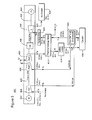
- an air handling unit 604 and a vapor absorption chiller 606 can be implemented in the beginning stages of a power generation system 602 as shown in Figure 6 .
- This system will now be described by generally following the flow of air in the system up to the first radial compressor 610 followed by describing the fluid loops in the air handling unit 604 and the vapor absorption chiller 606.
- step 9a air is brought into the air handling unit 604 and cooled, moisture is removed and the air is then taken into the axial compressor 608.
- the air is then compressed in the axial compressor 608, during which the air is put under pressure and undergoes an increase in temperature.
- This air is exhausted from the axial compressor 608 in step 9b, and undergoes heat exchange within a vapor absorption chiller 606.
- the cooled air flow then, in step 9c, departs the vapor absorption chiller 606 and enters the first radial compressor 610.
- the air is then compressed by the first radial compressor 610, exits the first radial compressor 610 and in step 9d enters a second radial compressor 10 for further compression.
- Elements 10-30 are similar to those shown in Figure 1 thus their description is omitted.
- the vapor absorption chiller 606 acts as a heat exchanger which in turn allows the exhaust air from the axial compressor 608 to be cooled to the desired temperature, as well as allowing the air handling unit 604 to cool the air prior to air entering the axial compressor 608 as will now be described with respect to Figure 7 .
- air enters the air handling unit 604 and is cooled by a cooling loop 702.
- Cooling loop 702 can include chilled water or a glycol solution. Additionally, moisture is removed from the air. This cooled air then goes to the axial compressor 608.
- the hot exhaust from the axial compressor 608 enters the vapor absorption chiller 606 and is cooled en route to the first radial compressor 610 by exchanging heat with a refrigerant in a generation stage 704.
- the refrigerant vapor within the vapor absorption chiller 606 is evaporated during the generation stage 704 and flows to a condenser 706.
- the condenser 706 includes a heat exchanger 708 and outputs a liquid refrigerant which in turn cools the cooling loop 702 as shown in heat exchanger 710. This refrigerant is then cooled by cooling loop 712 and pumped back by pump 714 to the generation stage 704. Additionally, some portion of the refrigerant that remains in a liquid form from the generation stage 704 enters the heat exchanger 710 and is also cooled by the cooling loop 712 prior to being pumped back to the generation stage 704.
- FIG. 8 an illustrative example with values of the pressures and temperatures of the air and oil at various points of the system shown in Figure 6 is shown in Figure 8 . These values are exemplary and not intended to limit the embodiments.
- the system in Figure 8 will operate as described above with respect to the system shown in Figure 6 thus this description is omitted.
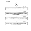
- a method for capturing heat energy in a power generation system includes: a step 902 of exhausting a first compressed, heated air flow from a first compressor; a step 904 of storing an oil in an insulated storage tank; a step 906 of receiving the first compressed heated air flow at the insulated storage tank; a step 908 of transferring heat energy from the first compressed heated air flow to the oil at the insulated storage tank; a step 910 of transferring heat energy from the oil after being heated, to a cooled, compressed air at the insulated storage tank; a step 912 of exhausting a second compressed, heated air flow by a second compressor; a step 914 of storing heat energy from the second compressed, heated air flow at an energy storage unit; a step 916 of storing the cooled, compressed air received from the energy storage unit at a storage facility; and a step 918 of selectively releasing the cooled,
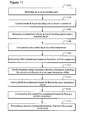
- a method for cooling air in a power generation system is shown in the flowchart of Figure 11 .
- the method includes: a step 1102 of receiving air at an air handling unit; a step 1104.
Landscapes
- Engineering & Computer Science (AREA)
- Chemical & Material Sciences (AREA)
- Combustion & Propulsion (AREA)
- Mechanical Engineering (AREA)
- General Engineering & Computer Science (AREA)
- Engine Equipment That Uses Special Cycles (AREA)
- Structures Of Non-Positive Displacement Pumps (AREA)
- Sorption Type Refrigeration Machines (AREA)
- Drying Of Solid Materials (AREA)
- Separation By Low-Temperature Treatments (AREA)
Abstract
Description
- The embodiments of the subject matter disclosed herein generally relate to power generation systems and more specifically to advanced adiabatic compressed air energy storage systems.
- As population increases, the desire for more electrical power is also generally increasing. Demand for this power typically varies during the course of a day with afternoon and early evening hours generally being the time of peak demand with later night and very early morning hours generally being the time of lowest demand for power. However, power generation systems need to meet both the lowest and highest demand systems for efficiently delivering power at the various demand levels.
- One system attempts to solve this problem by storing energy generated during off-peak demand hours for use during peak demand hours. This system is called an Advanced Adiabatic Compressed Air Energy Storage (AA-CAES) system and is shown in
Figure 1 as part of apower generation system 2. Thepower generation system 2 is now generally described by following the path of the air flow. Initially instep 3a, air is taken into anaxial compressor 4 and compressed during which the air is put under pressure and undergoes an increase in temperature. This air is exhausted instep 3b, and undergoes cooling at the Intercooler 6 to be cooled to the desired temperature for further compression. The air flow is then entered in step 3c to a firstradial compressor 8. The air is then compressed by the firstradial compressor 8, exits the firstradial compressor 8 and instep 3d enters a secondradial compressor 10 for further compression. - The air flow then goes, in
step 3e, from the secondradial compressor 10 to an energy storage unit, e.g., a Thermal Energy Store 12. The hot compressed air from the secondradial compressor 10 is then cooled by the Thermal Energy Store 12. The heat energy is stored in the Thermal Energy Store 12 for future use and any water that is generated by the cooling process is drained off. The cooled compressed air is then sent to aSafety Cooler 14 instep 3f, where the air is further cooled prior to being sent instep 3g to a storage facility, e.g.,cavern 16. This storage of the compressed air in thecavern 16 and the storage of the energy in the Thermal Energy Store 12 typically occurs during non-peak demand operation of thepower generation system 2. - When the demand for power from the
power generation system 2 increases to a desired point, energy output can be increased by releasing the stored compressed air back into the system to drive anexpander 18, e.g., a turbine. For example, thecavern 16 releases some of the stored compressed air, instep 3h, to the Thermal Energy Store 12 for heating. Heat energy is transferred from the Thermal Energy Store 12 to the compressed air and the heated compressed air flows to aparticle filter 20 instep 3i. The heated compressed air then flows, in step 3j, to an expansion section ofturbine 18. During expansion the air cools and undergoes a pressure drop while producing the work which drives theshaft 26 which in turn spins a portion of agenerator 30 for power generation. After expansion the air flows from theturbine 18 to anair outlet 22 instep 3k, typically for release to atmosphere.Power generation system 2 can also include ashaft 24 for the compressors, agear box 28 and amotor 32. - While the system shown in
Figure 1 does allow for storing energy for use during peak demand hours, it can be appreciated that power needs are going to grow and finding ways to meet the growing demand is desirable. - Accordingly, systems and methods for improving efficiency in power generation systems are desirable.
- According to an exemplary embodiment there is a system for cooling air in a power generation system. The system includes: an air handling unit configured to receive air, to cool the air and to remove moisture from the air; the first compressor fluidly connected to the air handling unit and configured to receive the air from the air handling unit and to exhaust a first compressed, heated air flow; a vapor absorption chiller connected to the first compressor and configured to transfer heat energy between a plurality of mediums and to cool the first compressed, heated air flow; a second compressor connected to the vapor absorption chiller and configured to receive the cooled first compressed, heated air flow and to exhaust a second compressed, heated air flow; an energy storage unit connected to the second compressor and configured to store heat energy from the second compressed, heated air flow; and a storage facility connected to the energy storage unit and configured to store a cooled, compressed air received from the energy storage unit and to selectively release the cooled, compressed air back into the power generation system.
- According to another exemplary embodiment there is a system for cooling air in a power generation system. The system includes: an air handling unit configured to receive air, to cool the air and to remove moisture from the air; a first compressor fluidly connected to the air handling unit and configured to receive the air from the air handling unit and to exhaust a first compressed, heated air flow; a vapor absorption chiller connected to the first compressor and configured to transfer heat energy between a plurality of mediums and to cool the first compressed, heated air flow; and a second compressor connected to the vapor absorption chiller and configured to receive the cooled first compressed, heated air flow and to exhaust a second compressed, heated air flow.
- According to another exemplary embodiment there is a method for cooling air in a power generation system. The method includes: receiving air at an air handling unit; cooling the air at the air handling unit; removing moisture from the air at the air handling unit; compressing air by a first compressor; exhausting a first compressed, heated air flow from the first compressor; transferring heat energy between a plurality of mediums at an vapor absorption chiller; cooling the first compressed, heated air flow at the vapor absorption chiller; compressing the cooled first compressed, heated air flow; and exhausting a second compressed, heated air flow.
- The accompanying drawings illustrate exemplary embodiments, wherein:
-
Figure 1 depicts a power generation system and an Advanced Adiabatic Compressed Air Energy Storage (AA-CAES) system; -
Figure 2 illustrates a power generation system and an efficient AA-CAES system according to exemplary embodiments; -
Figure 3 shows the system ofFigure 2 with illustrative values according to exemplary embodiments; -
Figure 4 illustrates a power generation system and an another efficient AA-CAES system according to exemplary embodiments; -
Figure 5 shows the system ofFigure 4 with illustrative values according to exemplary embodiments; -
Figure 6 illustrates an air cooling system in a power generation system according to exemplary embodiments; -
Figure 7 illustrates an air handler and a vapor absorption chiller according to exemplary embodiments; -
Figure 8 shows the system ofFigure 6 with illustrative values according to exemplary embodiments; -
Figures 9 and10 are flowcharts showing a method for capturing heat energy in a power generation system according to exemplary embodiments; and -
Figure 11 is a flowchart showing a method for cooling air in a power generation system according to exemplary embodiments. - The following detailed description of the exemplary embodiments refers to the accompanying drawings. The same reference numbers in different drawings identify the same or similar elements. Additionally, the drawings are not necessarily drawn to scale. Also, the following detailed description does not limit the invention. Instead, the scope of the invention is defined by the appended claims.
- Reference throughout the specification to "one embodiment" or "an embodiment" means that a particular feature, structure, or characteristic described in connection with an embodiment is included in at least one embodiment of the subject matter disclosed. Thus, the appearance of the phrases "in one embodiment" or "in an embodiment" in various places throughout the specification is not necessarily referring to the same embodiment. Further, the particular features, structures or characteristics may be combined in any suitable manner in one or more embodiments.
- As described in the Background section, systems and methods for improving efficiency in power generation systems are desirable. Exemplary embodiments described herein provide systems and methods for improving efficiency in power generation systems. According to exemplary embodiments, heat energy typically lost between compressors in a Compressed Air Energy Storage (CAES) system can be recovered for use in a modified adiabatic CAES (AA-CAES) system, an example of which is shown in
Figure 2 . - According to exemplary embodiments,
Figure 2 shows apower generation system 202 which includes a modified AA-CAES system which captures and stores the heat energy, which is typically lost between anaxial compressor 204 and aradial compressor 206, for use during peak or near peak load conditions. By capturing this heat energy there can be approximately an 8-10 percent improvement in overall operating efficiency of thepower generation system 202 when compared with thesystem 2 shown inFigure 1 . This system will now be described by generally following the flow of air in the system starting with an air intake to theaxial compressor 204. Initially instep 5a, air is taken into anaxial compressor 204 and compressed during which the air is put under pressure and undergoes an increase in temperature. This air is exhausted from theaxial compressor 204 instep 5b, and undergoes heat exchange in a heat exchanger, e.g., Intercooler 208, with oil which is in its own closed loop system. This heat exchange and the closed loop system for the oil are explained in more detail below. The cooled air flow then enters, instep 5c, the firstradial compressor 206. The air is then compressed by the firstradial compressor 206, exits the firstradial compressor 206 and instep 5d enters a secondradial compressor 210 for further compression. It is noted that more or less radial compressors may be used, for example thepower generation system 202 can include anaxial compressor 204 and a singleradial compressor 206. - The air flow then goes in
step 5e from the secondradial compressor 210 to an energy storage unit, e.g., aThermal Energy Store 212. The hot compressed air from the secondradial compressor 210 is then cooled by theThermal Energy Store 212. The heat energy is stored in theThermal Energy Store 212 for future use and any water that is generated by the cooling process is drained off. The cooled compressed air is then sent to aSafety Cooler 214 instep 5f, where the air is further cooled prior to being sent instep 5g to a storage facility, e.g.,cavern 216. This storage of the compressed air in thecavern 216 and the storage of the energy in theThermal Energy Store 212 typically occurs during non-peak demand operation of thepower generation system 202. - When the demand on the
power generation system 202 increases to a desired point, energy output can be increased by releasing the stored compressed air back into the system to drive anexpander 218, e.g., a turbine. For example, thecavern 216 releases some of the stored compressed air instep 5h which undergoes preheating in an insulatedhot oil tank 220. The released compressed air then flows to theThermal Energy Store 212 for heating instep 5i. Heat energy is transferred from theThermal Energy Store 212 to the compressed air and the heated compressed air flows (optionally) to aparticle filter 222 instep 5j. The heated compressed air then flows instep 5k from theparticle filter 222 to an expansion section ofturbine 218. During expansion the air cools and undergoes a pressure drop while producing the work which drives theshaft 224, which in turn spins a portion of agenerator 226 for generating power. After expansion the air flows from theturbine 218 to anair outlet 228 in step Sj, typically for release to atmosphere. Thepower generation system 202 can also include ashaft 230 for the compressors, agear box 234 and amotor 232 for driving thecompressor 204. - Returning now to the
Intercooler 208 and the closed loop oil system, the flow of the oil which supports the heat energy transfer described above will now be described. According to exemplary embodiments, oil is initially heated in theIntercooler 208 by the exhaust air from theaxial compressor 204. Other types of compressors may be used in thepower generation system 202. This heated oil is transferred from theIntercooler 208 by, e.g., ahot oil pump 236, to the insulatedhot oil tank 220. As previously described, heat is transferred from the hot oil to the compressed air when released from thecavern 216. This cooled oil is then pumped by acold oil pump 238 to acold oil tank 240 which is typically not insulated. From there the cooled oil is pumped back to theIntercooler 208 to continue the process again. The oil used for this closed loop heat transfer process can have a high specific heat. The oil may be any di-thermic oil, for example, a Dowtherm fluid that has a specific heat of 2.3 kJ/kg-K at substantially 250° C. - According to an exemplary embodiment, an illustrative example with values of pressures and temperatures of the air and oil at various points of the system shown in
Figure 2 is shown inFigure 3 . These values are exemplary and not intended to limit the embodiments. The system inFigure 3 will operate as described above with respect to the system shown inFigure 2 and thus this description is omitted. - According to another exemplary embodiment, heat energy can be captured and stored for future use in a
power generation system 402 as shown inFigure 4 . Thepower generation system 402 includes a modified AA-CAES system which stores the heat energy, which is typically lost between anaxial compressor 404 and aradial compressor 408, for use during peak or near peak load conditions. By capturing this heat energy there can be approximately an 8-10 percent improvement in an overall operating efficiency of thepower generation system 402. This system will now be described by generally following the flow of air in the system starting with air intake to theaxial compressor 404. Initially in step 7a, air is taken into anaxial compressor 404 and compressed during which the air is put under pressure and undergoes an increase in temperature. This air is exhausted from theaxial compressor 404 instep 7b, and undergoes heat exchange (i.e., heats an oil or another flow of air) with an insulatedhot oil tank 406. The cooled air flow then, instep 7c, departs the insulatedhot oil tank 406 and enters the firstradial compressor 408. The air is then compressed by the firstradial compressor 408, exits the firstradial compressor 408 and instep 7d enters a secondradial compressor 410 for further compression. The number of radial compressors can be different and also the type of compressors may be different. - The air flow then goes in step 7e from the second
radial compressor 410 to an energy storage unit, e.g., aThermal Energy Store 412. The hot compressed air from the secondradial compressor 410 is then cooled by theThermal Energy Store 412. The heat energy is stored in theThermal Energy Store 412 for future use and any water that is generated by the cooling process is drained off. The cooled compressed air is then sent to aSafety Cooler 414 instep 7f, where the air is further cooled prior to being sent instep 7g to a storage facility, e.g.,cavern 416. This storage of the compressed air in thecavern 416 and the storage of the heat energy in theThermal Energy Store 412 typically occurs during non-peak demand operation of thepower generation system 402. - When the demand on the
power generation system 402 increases to a desired point, energy output can be increased by releasing the stored compressed air back into the system to drive anexpander 418, e.g., a turbine. For example, thecavern 416 releases some of the stored compressed air instep 7h which undergoes preheating at the insulatedhot oil tank 406. The released compressed air then flows to theThermal Energy Store 412 for heating instep 7i. Heat energy is transferred from theThermal Energy Store 412 to the compressed air and the heated compressed air flows to aparticle filter 420 instep 7j. The heated compressed air then flows instep 7k from theparticle filter 420 to an expansion section ofturbine 418. During expansion the air cools and undergoes a pressure drop while producing the work which drives theshaft 422 which in turn spins a portion of agenerator 424 for generating power. After expansion the air flows from theturbine 418 to anair outlet 426 instep 71, typically for release to atmosphere.Power generation system 402 can also include ashaft 428 for the compressors, agear box 430 and amotor 432. - According to an exemplary embodiment, an illustrative example with values of the pressures and temperatures of the air and oil at various points of the system shown in
Figure 4 is shown inFigure 5 . These values are exemplary and not intended to limit the embodiments. The system inFigure 5 will operate as described above with respect to the system shown inFigure 4 thus this description is omitted. - According to another exemplary embodiment, an
air handling unit 604 and avapor absorption chiller 606 can be implemented in the beginning stages of apower generation system 602 as shown inFigure 6 . This allows thepower generation system 602 to cool the air going into theaxial compressor 608, remove moisture from this air (which in turn can reduce/remove the need for removing moisture from the air downstream at the Thermal Energy Store 12) and to reduce the temperature of the exhaust air from the axial compressor. This system will now be described by generally following the flow of air in the system up to the firstradial compressor 610 followed by describing the fluid loops in theair handling unit 604 and thevapor absorption chiller 606. Initially instep 9a, air is brought into theair handling unit 604 and cooled, moisture is removed and the air is then taken into theaxial compressor 608. The air is then compressed in theaxial compressor 608, during which the air is put under pressure and undergoes an increase in temperature. This air is exhausted from theaxial compressor 608 instep 9b, and undergoes heat exchange within avapor absorption chiller 606. The cooled air flow then, instep 9c, departs thevapor absorption chiller 606 and enters the firstradial compressor 610. The air is then compressed by the firstradial compressor 610, exits the firstradial compressor 610 and instep 9d enters a secondradial compressor 10 for further compression. Elements 10-30 are similar to those shown inFigure 1 thus their description is omitted. - According to exemplary embodiments, the
vapor absorption chiller 606 acts as a heat exchanger which in turn allows the exhaust air from theaxial compressor 608 to be cooled to the desired temperature, as well as allowing theair handling unit 604 to cool the air prior to air entering theaxial compressor 608 as will now be described with respect toFigure 7 . Initially, air enters theair handling unit 604 and is cooled by acooling loop 702.Cooling loop 702 can include chilled water or a glycol solution. Additionally, moisture is removed from the air. This cooled air then goes to theaxial compressor 608. The hot exhaust from theaxial compressor 608 enters thevapor absorption chiller 606 and is cooled en route to the firstradial compressor 610 by exchanging heat with a refrigerant in ageneration stage 704. - According to exemplary embodiments, the refrigerant vapor within the
vapor absorption chiller 606 is evaporated during thegeneration stage 704 and flows to acondenser 706. Thecondenser 706 includes aheat exchanger 708 and outputs a liquid refrigerant which in turn cools thecooling loop 702 as shown inheat exchanger 710. This refrigerant is then cooled by coolingloop 712 and pumped back bypump 714 to thegeneration stage 704. Additionally, some portion of the refrigerant that remains in a liquid form from thegeneration stage 704 enters theheat exchanger 710 and is also cooled by thecooling loop 712 prior to being pumped back to thegeneration stage 704. - According to an exemplary embodiment, an illustrative example with values of the pressures and temperatures of the air and oil at various points of the system shown in
Figure 6 is shown inFigure 8 . These values are exemplary and not intended to limit the embodiments. The system inFigure 8 will operate as described above with respect to the system shown inFigure 6 thus this description is omitted. - While the above described exemplary embodiments have shown three compressors in series and capturing the heat energy between the axial and the radial compressors, other exemplary variations exist. For example, other quantities and types of compressors could be used, such as one axial and one radial compressor. Additionally, heat energy can be captured for future use from the exhaust of other compressors as desired.
- Utilizing the above-described exemplary systems according to exemplary embodiments, a method for capturing heat energy in a power generation system is shown in the flowchart of
Figures 9 and10 . The method includes: astep 902 of exhausting a first compressed, heated air flow from a first compressor; a step 904 of storing an oil in an insulated storage tank; astep 906 of receiving the first compressed heated air flow at the insulated storage tank; astep 908 of transferring heat energy from the first compressed heated air flow to the oil at the insulated storage tank; astep 910 of transferring heat energy from the oil after being heated, to a cooled, compressed air at the insulated storage tank; astep 912 of exhausting a second compressed, heated air flow by a second compressor; astep 914 of storing heat energy from the second compressed, heated air flow at an energy storage unit; astep 916 of storing the cooled, compressed air received from the energy storage unit at a storage facility; and astep 918 of selectively releasing the cooled, compressed air for use in power generation by the storage facility. - Utilizing the above-described exemplary systems according to exemplary embodiments, a method for cooling air in a power generation system is shown in the flowchart of
Figure 11 . The method includes: astep 1102 of receiving air at an air handling unit; astep 1104. of cooling the air at the air handling unit to obtain a cooled air; astep 1106 of removing moisture from the cooled air at the air handling unit to obtain a cooled, dry air; astep 1108 of compressing air by a first compressor; astep 1110 of exhausting a first compressed, heated air flow from the first compressor; astep 1112 of transferring heat energy between a plurality of mediums including the compressed, heated air at a vapor absorption chiller; astep 1114 of cooling the first compressed, heated air flow at the vapor absorption chiller; astep 1116 of compressing the cooled first compressed, heated air flow at a second compressor; and astep 1118 of exhausting a second compressed, heated air flow from the second compressor. - The above-described exemplary embodiments are intended to be illustrative in all respects, rather than restrictive, of the present invention. Thus the present invention is capable of many variations in detailed implementation that can be derived from the description contained herein by a person skilled in the art. All such variations and modifications are considered to be within the scope and spirit of the present invention as defined by the following claims. No element, act, or instruction used in the description of the present application should be construed as critical or essential to the invention unless explicitly described as such. Also, as used herein, the article "a" is intended to include one or more items.
- This written description uses examples of the subject matter disclosed to enable any person skilled in the art to practice the same, including making and using any devices or systems and performing any incorporated methods. The patentable scope of the subject matter is defined by the claims, and may include other examples that occur to those skilled in the art. Such other examples are intended to be within the scope of the claims.
Various aspects and embodiments of the present invention are defined by the following numbered clauses: - 1. A system for cooling air in a power generation system, the system comprising:
- an air handling unit configured to receive air, to cool the air, and to remove moisture from the air;
- a first compressor fluidly connected to the air handling unit and configured to receive the air from the air handling unit and to exhaust a first compressed, heated air flow;
- a vapor absorption chiller connected to the first compressor configured to transfer heat energy between a plurality of mediums and to cool the first compressed, heated air flow;
- a second compressor connected to the vapor absorption chiller configured to receive the cooled first compressed, heated air flow and to exhaust a second compressed, heated air flow;
- an energy storage unit connected to the second compressor and configured to store heat energy from the second compressed, heated air flow; and
- a storage facility connected to the energy storage unit and configured to store a cooled, compressed air received from the energy storage unit and to selectively release the cooled, compressed air back into the power generation system.
- 2. The system of
clause 1, wherein the vapor absorption chiller configured to transfer heat energy between a plurality of mediums and to cool the first compressed, heated air flow comprises:- a first heat exchanger configured to transfer heat energy from the first compressed, heated air flow to a refrigerant;
- a second heat exchanger fluidly connected to the first heat exchanger and configured to cool and to condense the refrigerant;
- a third heat exchanger fluidly connected to the second heat exchanger and configured to transfer heat energy from a first fluid to the refrigerant, wherein the first fluid then cools the air received by the air handling unit; and
- a fourth heat exchanger fluidly connected to the third heat exchanger and configured to transfer heat energy from the refrigerant to a second fluid.
- 3. The system of
clause 1 orclause 2, wherein the first fluid is one of water or glycol. - 4. The system of any preceding clause, wherein the vapor absorption chiller further comprises:
- a pump configured to pump the refrigerant.
- 5. The system of any preceding clause, wherein the first compressor is an axial compressor and the second compressor is a radial compressor.
- 6. The system of any preceding clause, wherein the third heat exchanger is connected to both the air handling unit and the vapor absorption chiller.
- 7. The system of any preceding clause, wherein the cooled first compressed, heated air flow is at a temperature of substantially 180° C.
- 8. A system for cooling air in a power generation system, the system comprising:
- an air handling unit configured to receive air, to cool the air and to remove moisture from the air;
- a first compressor fluidly connected to the air handling unit and configured to receive the air from the air handling unit and to exhaust a first compressed, heated air flow;
- a vapor absorption chiller connected to the first compressor and configured to transfer heat energy between a plurality of mediums and to cool the first compressed, heated air flow; and
- a second compressor connected to the vapor absorption chiller and configured to receive the cooled first compressed, heated air flow and to exhaust a second compressed, heated air flow.
- 9. The system of any preceding clause, wherein the vapor absorption chiller configured to transfer heat energy between a plurality of mediums and to cool the first compressed, heated air flow comprises:
- a first heat exchanger configured to transfer heat energy from the first compressed, heated air flow to a refrigerant;
- a second heat exchanger fluidly connected to the first heat exchanger and configured to cool and to condense the refrigerant;
- a third heat exchanger fluidly connected to the second heat exchanger and configured to transfer heat energy from a first fluid to the refrigerant, wherein the fluid then cools the air received by the air handling unit; and
- a fourth heat exchanger fluidly connected to the third heat exchanger and configured to transfer heat energy from the refrigerant to a second fluid.
- 10. The system of any preceding clause, wherein the first fluid is one of water or glycol.
- 11. The system of any preceding clause, wherein the vapor absorption chiller further comprises:
- a pump configured to pump the refrigerant.
- 12. The system of any preceding clause, wherein the first compressor is an axial compressor and the second compressor is a radial compressor.
- 13. The system of any preceding clause, wherein the third heat exchanger is connected to both the air handling unit and the vapor absorption chiller.
- 14. The system of any preceding clause, wherein the cooled first compressed, heated air flow is at a temperature of substantially 180° C.
- 15. A method for cooling air in a power generation system, the method comprising:
- receiving air at an air handling unit;
- cooling the air at the air handling unit to obtain a cooled air;
- removing moisture from the cooled air at the air handling unit to obtain a cooled, dry air;
- compressing the cooled, dry air by a first compressor;
- exhausting a first compressed, heated air flow from the first compressor;
- transferring heat energy between a plurality of mediums including the compressed, heated air at an vapor absorption chiller;
- cooling the first compressed, heated air flow at the vapor absorption chiller;
- compressing the cooled first compressed, heated air flow at a second compressor; and
- exhausting a second compressed, heated air flow from the second compressor.
- 16. The method of
clause 15, further comprising:- transferring heat energy from the first compressed, heated air flow to a refrigerant at a first heat exchanger in the vapor absorption chiller;
- cooling the refrigerant at a second heat exchanger in the vapor absorption chiller;
- condensing the refrigerant at the second heat exchanger in the vapor absorption chiller;
- transferring heat energy from a first fluid to the refrigerant at a third heat exchanger in the vapor absorption chiller, wherein the fluid then cools the air received by the air handling unit; and
- transferring heat energy from the refrigerant to a second fluid at a fourth heat exchanger in the vapor absorption chiller.
- 17. The method of
clause 15 orclause 16, wherein the first fluid is one of water or glycol. - 18. The method of any of
clauses 15 to 17, further comprising:- pumping the refrigerant by a pump.
- 19. The method of any of
clauses 15 to 18, wherein the first compressor is an axial compressor. - 20. The method of any of
clauses 15 to 19, wherein the cooled first compressed, heated air flow is at a temperature of substantially 180° C.
Claims (14)
- A system for cooling air in a power generation system, the system comprising:an air handling unit configured to receive air, to cool the air, and to remove moisture from the air;a first compressor fluidly connected to the air handling unit and configured to receive the air from the air handling unit and to exhaust a first compressed, heated air flow;a vapor absorption chiller connected to the first compressor configured to transfer heat energy between a plurality of mediums and to cool the first compressed, heated air flow;a second compressor connected to the vapor absorption chiller configured to receive the cooled first compressed, heated air flow and to exhaust a second compressed, heated air flow;an energy storage unit connected to the second compressor and configured to store heat energy from the second compressed, heated air flow; anda storage facility connected to the energy storage unit and configured to store a cooled, compressed air received from the energy storage unit and to selectively release the cooled, compressed air back into the power generation system.
- A system for cooling air in a power generation system, the system comprising:an air handling unit configured to receive air, to cool the air and to remove moisture from the air;a first compressor fluidly connected to the air handling unit and configured to receive the air from the air handling unit and to exhaust a first compressed, heated air flow;a vapor absorption chiller connected to the first compressor and configured to transfer heat energy between a plurality of mediums and to cool the first compressed, heated air flow; anda second compressor connected to the vapor absorption chiller and configured to receive the cooled first compressed, heated air flow and to exhaust a second compressed, heated air flow.
- The system of claim 1 or claim 2, wherein the vapor absorption chiller configured to transfer heat energy between a plurality of mediums and to cool the first compressed, heated air flow comprises:a first heat exchanger configured to transfer heat energy from the first compressed, heated air flow to a refrigerant;a second heat exchanger fluidly connected to the first heat exchanger and configured to cool and to condense the refrigerant;a third heat exchanger fluidly connected to the second heat exchanger and configured to transfer heat energy from a first fluid to the refrigerant, wherein the first fluid then cools the air received by the air handling unit; anda fourth heat exchanger fluidly connected to the third heat exchanger and configured to transfer heat energy from the refrigerant to a second fluid.
- The system of any preceding claim, wherein the first fluid is one of water or glycol.
- The system of any preceding claim, wherein the vapor absorption chiller further comprises:a pump configured to pump the refrigerant.
- The system of any preceding claim, wherein the first compressor is an axial compressor and the second compressor is a radial compressor.
- The system of any preceding claim, wherein the third heat exchanger is connected to both the air handling unit and the vapor absorption chiller.
- The system of any preceding claim, wherein the cooled first compressed, heated air flow is at a temperature of substantially 180° C.
- A method for cooling air in a power generation system, the method comprising:receiving air at an air handling unit;cooling the air at the air handling unit to obtain a cooled air;removing moisture from the cooled air at the air handling unit to obtain a cooled, dry air;compressing the cooled, dry air by a first compressor;exhausting a first compressed, heated air flow from the first compressor;transferring heat energy between a plurality of mediums including the compressed, heated air at an vapor absorption chiller;cooling the first compressed, heated air flow at the vapor absorption chiller;compressing the cooled first compressed, heated air flow at a second compressor; andexhausting a second compressed, heated air flow from the second compressor.
- The method of claim 9, further comprising:transferring heat energy from the first compressed, heated air flow to a refrigerant at a first heat exchanger in the vapor absorption chiller;cooling the refrigerant at a second heat exchanger in the vapor absorption chiller;condensing the refrigerant at the second heat exchanger in the vapor absorption chiller;transferring heat energy from a first fluid to the refrigerant at a third heat exchanger in the vapor absorption chiller, wherein the fluid then cools the air received by the air handling unit; andtransferring heat energy from the refrigerant to a second fluid at a fourth heat exchanger in the vapor absorption chiller.
- The method of claim 9 or claim 10, wherein the first fluid is one of water or glycol.
- The method of any of claims 9 to 11, further comprising:pumping the refrigerant by a pump.
- The method of any of claims 9 to 12, wherein the first compressor is an axial compressor.
- The method of any of claims 9 to 13, wherein the cooled first compressed, heated air flow is at a temperature of substantially 180° C.
Applications Claiming Priority (1)
| Application Number | Priority Date | Filing Date | Title |
|---|---|---|---|
| US12/915,422 US20120102987A1 (en) | 2010-10-29 | 2010-10-29 | Inlet Air Cooling and Moisture Removal Methods and Devices in Advance Adiabatic Compressed Air Energy Storage Systems |
Publications (3)
| Publication Number | Publication Date |
|---|---|
| EP2447505A2 true EP2447505A2 (en) | 2012-05-02 |
| EP2447505A3 EP2447505A3 (en) | 2018-02-28 |
| EP2447505B1 EP2447505B1 (en) | 2019-11-27 |
Family
ID=44862740
Family Applications (1)
| Application Number | Title | Priority Date | Filing Date |
|---|---|---|---|
| EP11186992.1A Active EP2447505B1 (en) | 2010-10-29 | 2011-10-27 | Inlet air cooling and moisture removal methods and devices in advanced adiabatic compressed air energy storage systems |
Country Status (5)
| Country | Link |
|---|---|
| US (1) | US20120102987A1 (en) |
| EP (1) | EP2447505B1 (en) |
| JP (1) | JP5981704B2 (en) |
| CN (1) | CN102538531A (en) |
| RU (1) | RU2559793C2 (en) |
Cited By (4)
| Publication number | Priority date | Publication date | Assignee | Title |
|---|---|---|---|---|
| EP2581584A1 (en) * | 2011-10-13 | 2013-04-17 | Alstom Technology Ltd | Compressed air energy storage system and method for operating this system |
| WO2016089659A1 (en) * | 2014-12-05 | 2016-06-09 | General Electric Company | A cooling system for an energy system and method of operating the same |
| EP3477077A1 (en) * | 2017-10-24 | 2019-05-01 | Aarhus Universitet | Combined subcooling temperature scaes and solar powered absorption chiller |
| US11591957B2 (en) | 2017-10-24 | 2023-02-28 | Tes Caes Technology Limited | Energy storage apparatus and method |
Families Citing this family (16)
| Publication number | Priority date | Publication date | Assignee | Title |
|---|---|---|---|---|
| GB2493726A (en) * | 2011-08-16 | 2013-02-20 | Alstom Technology Ltd | Adiabatic compressed air energy storage system |
| WO2014161065A1 (en) * | 2013-04-03 | 2014-10-09 | Sigma Energy Storage Inc. | Compressed air energy storage and recovery |
| CN103225598B (en) * | 2013-04-27 | 2015-11-18 | 清华大学 | The method and system of a kind of pressurized air and heat-storage medium energy storage simultaneously |
| ITFI20130299A1 (en) * | 2013-12-16 | 2015-06-17 | Nuovo Pignone Srl | "IMPROVEMENTS IN COMPRESSED-AIR-ENERGY-STORAGE (CAES) SYSTEMS AND METHODS" |
| US9920692B2 (en) * | 2014-05-30 | 2018-03-20 | Distributed Storage Technologies LLC | Cooling systems and methods using pressurized fuel |
| WO2016047630A1 (en) * | 2014-09-25 | 2016-03-31 | 株式会社神戸製鋼所 | Container-type compressed air storage power generation device |
| JP6452450B2 (en) * | 2014-09-25 | 2019-01-16 | 株式会社神戸製鋼所 | Container type compressed air storage power generator |
| KR102403512B1 (en) | 2015-04-30 | 2022-05-31 | 삼성전자주식회사 | Outdoor unit of air conditioner, control device applying the same |
| JP6373794B2 (en) * | 2015-05-08 | 2018-08-15 | 株式会社神戸製鋼所 | Compressed air storage power generation apparatus and compressed air storage power generation method |
| JP6387325B2 (en) * | 2015-05-11 | 2018-09-05 | 株式会社神戸製鋼所 | Compressed air storage generator |
| CN107218132B (en) * | 2016-04-17 | 2018-10-09 | 厦门典力节能科技有限公司 | Intelligent grid electric load energy storage dispatching method |
| CN107299891B (en) * | 2016-10-12 | 2019-10-18 | 清华大学 | A non-supplementary combustion compressed air energy storage system |
| US11305879B2 (en) | 2018-03-23 | 2022-04-19 | Raytheon Technologies Corporation | Propulsion system cooling control |
| CN109687486A (en) * | 2018-12-25 | 2019-04-26 | 华中科技大学 | Microgrid operation method and system under Demand Side Response containing electric automobile charging station |
| CN114790923B (en) * | 2022-04-18 | 2023-07-25 | 南京航空航天大学 | Feed liquid separation power circulation system combined with humidifying and dehumidifying technology and working method |
| CN116241436B (en) * | 2023-03-17 | 2024-04-16 | 中国电力工程顾问集团中南电力设计院有限公司 | Compressed air energy storage system and method for constant-parameter operation of all-weather compressor inlet |
Family Cites Families (22)
| Publication number | Priority date | Publication date | Assignee | Title |
|---|---|---|---|---|
| US2690656A (en) * | 1949-03-24 | 1954-10-05 | Cummings William Warren | Method of air conditioning |
| US3895499A (en) * | 1974-05-29 | 1975-07-22 | Borg Warner | Absorption refrigeration system and method |
| GB1583648A (en) * | 1976-10-04 | 1981-01-28 | Acres Consulting Services | Compressed air power storage systems |
| US4329851A (en) * | 1978-06-08 | 1982-05-18 | Carrier Corporation | Absorption refrigeration system |
| JPS55134716A (en) * | 1979-04-04 | 1980-10-20 | Setsuo Yamamoto | Gas-turbine system |
| US4936109A (en) * | 1986-10-06 | 1990-06-26 | Columbia Energy Storage, Inc. | System and method for reducing gas compressor energy requirements |
| JPS63208627A (en) * | 1987-02-26 | 1988-08-30 | Mitsubishi Heavy Ind Ltd | Air storage type gas turbine device |
| US4849648A (en) * | 1987-08-24 | 1989-07-18 | Columbia Energy Storage, Inc. | Compressed gas system and method |
| JPH0354326A (en) * | 1989-07-20 | 1991-03-08 | Nkk Corp | Surplus power utilizing system |
| JPH02290495A (en) * | 1990-04-09 | 1990-11-30 | Kobe Steel Ltd | Air cooler of oil-free type screw air compressor |
| JP3507541B2 (en) * | 1994-03-11 | 2004-03-15 | 株式会社東芝 | Gas turbine plant |
| US5657643A (en) * | 1996-02-28 | 1997-08-19 | The Pritchard Corporation | Closed loop single mixed refrigerant process |
| US6920759B2 (en) * | 1996-12-24 | 2005-07-26 | Hitachi, Ltd. | Cold heat reused air liquefaction/vaporization and storage gas turbine electric power system |
| JP3750474B2 (en) * | 2000-03-08 | 2006-03-01 | 株式会社日立製作所 | Cogeneration facility and operation method thereof |
| RU2214564C2 (en) * | 2001-07-18 | 2003-10-20 | Белостоцкий Юрий Григорьевич | Cooling device and method of operation thereof |
| JP2003065628A (en) * | 2001-08-27 | 2003-03-05 | Mitsubishi Heavy Ind Ltd | Absorption refrigerating machine, equipment using absorption refrigerating machine and gas turbine suction air cooling device |
| EP1549892A1 (en) * | 2002-09-30 | 2005-07-06 | BP Corporation North America Inc. | Reduced carbon dioxide emission system and method for providing power for refrigerant compression and electrical power for a light hydrocarbon gas liquefaction process |
| WO2007008225A2 (en) * | 2004-08-14 | 2007-01-18 | The State Of Oregon Acting By And Through The State Board Of Higher Education On Behalf Of Oregon State University | Heat-activated heat-pump systems including integrated expander/compressor and regenerator |
| RU2273742C1 (en) * | 2004-09-03 | 2006-04-10 | ООО "Центр КОРТЭС" | Energy-accumulating plant |
| JP4279245B2 (en) * | 2004-12-06 | 2009-06-17 | 本田技研工業株式会社 | Gas turbine engine |
| RU2009114582A (en) * | 2009-04-20 | 2010-10-27 | Сергей Иванович Петров (RU) | METHOD FOR COOLING THE OBJECT AND THE COOLING DEVICE FOR IMPLEMENTATION OF THE SPECIFIED METHOD |
| US8341964B2 (en) * | 2009-10-27 | 2013-01-01 | General Electric Company | System and method of using a compressed air storage system with a gas turbine |
-
2010
- 2010-10-29 US US12/915,422 patent/US20120102987A1/en not_active Abandoned
-
2011
- 2011-10-25 JP JP2011233555A patent/JP5981704B2/en active Active
- 2011-10-27 EP EP11186992.1A patent/EP2447505B1/en active Active
- 2011-10-28 CN CN2011103461275A patent/CN102538531A/en active Pending
- 2011-10-28 RU RU2011143462/07A patent/RU2559793C2/en not_active IP Right Cessation
Non-Patent Citations (1)
| Title |
|---|
| None |
Cited By (4)
| Publication number | Priority date | Publication date | Assignee | Title |
|---|---|---|---|---|
| EP2581584A1 (en) * | 2011-10-13 | 2013-04-17 | Alstom Technology Ltd | Compressed air energy storage system and method for operating this system |
| WO2016089659A1 (en) * | 2014-12-05 | 2016-06-09 | General Electric Company | A cooling system for an energy system and method of operating the same |
| EP3477077A1 (en) * | 2017-10-24 | 2019-05-01 | Aarhus Universitet | Combined subcooling temperature scaes and solar powered absorption chiller |
| US11591957B2 (en) | 2017-10-24 | 2023-02-28 | Tes Caes Technology Limited | Energy storage apparatus and method |
Also Published As
| Publication number | Publication date |
|---|---|
| RU2011143462A (en) | 2013-05-10 |
| CN102538531A (en) | 2012-07-04 |
| US20120102987A1 (en) | 2012-05-03 |
| EP2447505A3 (en) | 2018-02-28 |
| RU2559793C2 (en) | 2015-08-10 |
| JP2012097736A (en) | 2012-05-24 |
| EP2447505B1 (en) | 2019-11-27 |
| JP5981704B2 (en) | 2016-08-31 |
Similar Documents
| Publication | Publication Date | Title |
|---|---|---|
| EP2447505B1 (en) | Inlet air cooling and moisture removal methods and devices in advanced adiabatic compressed air energy storage systems | |
| EP2447501B1 (en) | Systems and methods for pre-heating compressed air in advanced adiabatic compressed air energy storage systems | |
| EP2499342B1 (en) | System and method for secondary energy production in a compressed air energy storage system | |
| CN203626907U (en) | Power generation station | |
| CA2821108C (en) | Energy storage system and method for energy storage | |
| EP3186491B1 (en) | Method for cooling of the compressed gas of a compressor installation and compressor installation in which this method is applied | |
| CN116018493B (en) | Multi-temperature heat pump for storing heat energy | |
| CN103827448A (en) | Installation for storing thermal energy and method for the operation thereof | |
| CN114060111B (en) | Liquid compressed air energy storage method and system for utilizing waste heat of circulating water of thermal power generating unit | |
| US20160160864A1 (en) | Cooling system for an energy storage system and method of operating the same | |
| JP2016142272A (en) | Electrical energy storage and release system | |
| KR102340321B1 (en) | Electric Power facility with Liquid Air Energy System | |
| CN104169542A (en) | Electricity generation device and method | |
| WO2012047572A2 (en) | Method and system to produce electric power | |
| JP2016211465A (en) | Compressed air storage generator | |
| AU2020469637A1 (en) | Plant and process for energy storage | |
| KR20200108347A (en) | Gas fluid compression by alternating refrigeration and mechanical compression | |
| CN106150574A (en) | A kind of deep cooling liquid air energy storage systems of air interstage cooling | |
| JP2026512731A (en) | Plants and methods for energy management | |
| CN109296418B (en) | Method and device for converting pressure energy into electrical energy | |
| CN120291946A (en) | A liquid air energy storage system coupled with LNG cold energy Rankine cycle power generation | |
| WO2024246558A1 (en) | Method and apparatus for pre-heating a process gas |
Legal Events
| Date | Code | Title | Description |
|---|---|---|---|
| PUAI | Public reference made under article 153(3) epc to a published international application that has entered the european phase |
Free format text: ORIGINAL CODE: 0009012 |
|
| AK | Designated contracting states |
Kind code of ref document: A2 Designated state(s): AL AT BE BG CH CY CZ DE DK EE ES FI FR GB GR HR HU IE IS IT LI LT LU LV MC MK MT NL NO PL PT RO RS SE SI SK SM TR |
|
| AX | Request for extension of the european patent |
Extension state: BA ME |
|
| PUAL | Search report despatched |
Free format text: ORIGINAL CODE: 0009013 |
|
| AK | Designated contracting states |
Kind code of ref document: A3 Designated state(s): AL AT BE BG CH CY CZ DE DK EE ES FI FR GB GR HR HU IE IS IT LI LT LU LV MC MK MT NL NO PL PT RO RS SE SI SK SM TR |
|
| AX | Request for extension of the european patent |
Extension state: BA ME |
|
| RIC1 | Information provided on ipc code assigned before grant |
Ipc: F02C 7/141 20060101ALI20180123BHEP Ipc: F02C 6/16 20060101AFI20180123BHEP |
|
| STAA | Information on the status of an ep patent application or granted ep patent |
Free format text: STATUS: REQUEST FOR EXAMINATION WAS MADE |
|
| 17P | Request for examination filed |
Effective date: 20180828 |
|
| RBV | Designated contracting states (corrected) |
Designated state(s): AL AT BE BG CH CY CZ DE DK EE ES FI FR GB GR HR HU IE IS IT LI LT LU LV MC MK MT NL NO PL PT RO RS SE SI SK SM TR |
|
| GRAP | Despatch of communication of intention to grant a patent |
Free format text: ORIGINAL CODE: EPIDOSNIGR1 |
|
| STAA | Information on the status of an ep patent application or granted ep patent |
Free format text: STATUS: GRANT OF PATENT IS INTENDED |
|
| INTG | Intention to grant announced |
Effective date: 20190204 |
|
| GRAS | Grant fee paid |
Free format text: ORIGINAL CODE: EPIDOSNIGR3 |
|
| GRAA | (expected) grant |
Free format text: ORIGINAL CODE: 0009210 |
|
| STAA | Information on the status of an ep patent application or granted ep patent |
Free format text: STATUS: THE PATENT HAS BEEN GRANTED |
|
| AK | Designated contracting states |
Kind code of ref document: B1 Designated state(s): AL AT BE BG CH CY CZ DE DK EE ES FI FR GB GR HR HU IE IS IT LI LT LU LV MC MK MT NL NO PL PT RO RS SE SI SK SM TR |
|
| REG | Reference to a national code |
Ref country code: GB Ref legal event code: FG4D |
|
| REG | Reference to a national code |
Ref country code: CH Ref legal event code: EP |
|
| REG | Reference to a national code |
Ref country code: AT Ref legal event code: REF Ref document number: 1206911 Country of ref document: AT Kind code of ref document: T Effective date: 20191215 |
|
| REG | Reference to a national code |
Ref country code: DE Ref legal event code: R096 Ref document number: 602011063613 Country of ref document: DE |
|
| REG | Reference to a national code |
Ref country code: IE Ref legal event code: FG4D |
|
| REG | Reference to a national code |
Ref country code: NL Ref legal event code: MP Effective date: 20191127 |
|
| REG | Reference to a national code |
Ref country code: LT Ref legal event code: MG4D |
|
| PG25 | Lapsed in a contracting state [announced via postgrant information from national office to epo] |
Ref country code: ES Free format text: LAPSE BECAUSE OF FAILURE TO SUBMIT A TRANSLATION OF THE DESCRIPTION OR TO PAY THE FEE WITHIN THE PRESCRIBED TIME-LIMIT Effective date: 20191127 Ref country code: GR Free format text: LAPSE BECAUSE OF FAILURE TO SUBMIT A TRANSLATION OF THE DESCRIPTION OR TO PAY THE FEE WITHIN THE PRESCRIBED TIME-LIMIT Effective date: 20200228 Ref country code: NO Free format text: LAPSE BECAUSE OF FAILURE TO SUBMIT A TRANSLATION OF THE DESCRIPTION OR TO PAY THE FEE WITHIN THE PRESCRIBED TIME-LIMIT Effective date: 20200227 Ref country code: FI Free format text: LAPSE BECAUSE OF FAILURE TO SUBMIT A TRANSLATION OF THE DESCRIPTION OR TO PAY THE FEE WITHIN THE PRESCRIBED TIME-LIMIT Effective date: 20191127 Ref country code: LT Free format text: LAPSE BECAUSE OF FAILURE TO SUBMIT A TRANSLATION OF THE DESCRIPTION OR TO PAY THE FEE WITHIN THE PRESCRIBED TIME-LIMIT Effective date: 20191127 Ref country code: NL Free format text: LAPSE BECAUSE OF FAILURE TO SUBMIT A TRANSLATION OF THE DESCRIPTION OR TO PAY THE FEE WITHIN THE PRESCRIBED TIME-LIMIT Effective date: 20191127 Ref country code: BG Free format text: LAPSE BECAUSE OF FAILURE TO SUBMIT A TRANSLATION OF THE DESCRIPTION OR TO PAY THE FEE WITHIN THE PRESCRIBED TIME-LIMIT Effective date: 20200227 Ref country code: LV Free format text: LAPSE BECAUSE OF FAILURE TO SUBMIT A TRANSLATION OF THE DESCRIPTION OR TO PAY THE FEE WITHIN THE PRESCRIBED TIME-LIMIT Effective date: 20191127 Ref country code: SE Free format text: LAPSE BECAUSE OF FAILURE TO SUBMIT A TRANSLATION OF THE DESCRIPTION OR TO PAY THE FEE WITHIN THE PRESCRIBED TIME-LIMIT Effective date: 20191127 |
|
| PG25 | Lapsed in a contracting state [announced via postgrant information from national office to epo] |
Ref country code: RS Free format text: LAPSE BECAUSE OF FAILURE TO SUBMIT A TRANSLATION OF THE DESCRIPTION OR TO PAY THE FEE WITHIN THE PRESCRIBED TIME-LIMIT Effective date: 20191127 Ref country code: HR Free format text: LAPSE BECAUSE OF FAILURE TO SUBMIT A TRANSLATION OF THE DESCRIPTION OR TO PAY THE FEE WITHIN THE PRESCRIBED TIME-LIMIT Effective date: 20191127 Ref country code: IS Free format text: LAPSE BECAUSE OF FAILURE TO SUBMIT A TRANSLATION OF THE DESCRIPTION OR TO PAY THE FEE WITHIN THE PRESCRIBED TIME-LIMIT Effective date: 20200327 |
|
| PG25 | Lapsed in a contracting state [announced via postgrant information from national office to epo] |
Ref country code: AL Free format text: LAPSE BECAUSE OF FAILURE TO SUBMIT A TRANSLATION OF THE DESCRIPTION OR TO PAY THE FEE WITHIN THE PRESCRIBED TIME-LIMIT Effective date: 20191127 |
|
| PG25 | Lapsed in a contracting state [announced via postgrant information from national office to epo] |
Ref country code: PT Free format text: LAPSE BECAUSE OF FAILURE TO SUBMIT A TRANSLATION OF THE DESCRIPTION OR TO PAY THE FEE WITHIN THE PRESCRIBED TIME-LIMIT Effective date: 20200419 Ref country code: EE Free format text: LAPSE BECAUSE OF FAILURE TO SUBMIT A TRANSLATION OF THE DESCRIPTION OR TO PAY THE FEE WITHIN THE PRESCRIBED TIME-LIMIT Effective date: 20191127 Ref country code: RO Free format text: LAPSE BECAUSE OF FAILURE TO SUBMIT A TRANSLATION OF THE DESCRIPTION OR TO PAY THE FEE WITHIN THE PRESCRIBED TIME-LIMIT Effective date: 20191127 Ref country code: CZ Free format text: LAPSE BECAUSE OF FAILURE TO SUBMIT A TRANSLATION OF THE DESCRIPTION OR TO PAY THE FEE WITHIN THE PRESCRIBED TIME-LIMIT Effective date: 20191127 Ref country code: DK Free format text: LAPSE BECAUSE OF FAILURE TO SUBMIT A TRANSLATION OF THE DESCRIPTION OR TO PAY THE FEE WITHIN THE PRESCRIBED TIME-LIMIT Effective date: 20191127 |
|
| REG | Reference to a national code |
Ref country code: DE Ref legal event code: R097 Ref document number: 602011063613 Country of ref document: DE |
|
| PG25 | Lapsed in a contracting state [announced via postgrant information from national office to epo] |
Ref country code: SM Free format text: LAPSE BECAUSE OF FAILURE TO SUBMIT A TRANSLATION OF THE DESCRIPTION OR TO PAY THE FEE WITHIN THE PRESCRIBED TIME-LIMIT Effective date: 20191127 Ref country code: SK Free format text: LAPSE BECAUSE OF FAILURE TO SUBMIT A TRANSLATION OF THE DESCRIPTION OR TO PAY THE FEE WITHIN THE PRESCRIBED TIME-LIMIT Effective date: 20191127 |
|
| REG | Reference to a national code |
Ref country code: AT Ref legal event code: MK05 Ref document number: 1206911 Country of ref document: AT Kind code of ref document: T Effective date: 20191127 |
|
| PLBE | No opposition filed within time limit |
Free format text: ORIGINAL CODE: 0009261 |
|
| STAA | Information on the status of an ep patent application or granted ep patent |
Free format text: STATUS: NO OPPOSITION FILED WITHIN TIME LIMIT |
|
| 26N | No opposition filed |
Effective date: 20200828 |
|
| PG25 | Lapsed in a contracting state [announced via postgrant information from national office to epo] |
Ref country code: SI Free format text: LAPSE BECAUSE OF FAILURE TO SUBMIT A TRANSLATION OF THE DESCRIPTION OR TO PAY THE FEE WITHIN THE PRESCRIBED TIME-LIMIT Effective date: 20191127 Ref country code: AT Free format text: LAPSE BECAUSE OF FAILURE TO SUBMIT A TRANSLATION OF THE DESCRIPTION OR TO PAY THE FEE WITHIN THE PRESCRIBED TIME-LIMIT Effective date: 20191127 Ref country code: PL Free format text: LAPSE BECAUSE OF FAILURE TO SUBMIT A TRANSLATION OF THE DESCRIPTION OR TO PAY THE FEE WITHIN THE PRESCRIBED TIME-LIMIT Effective date: 20191127 |
|
| PG25 | Lapsed in a contracting state [announced via postgrant information from national office to epo] |
Ref country code: MC Free format text: LAPSE BECAUSE OF FAILURE TO SUBMIT A TRANSLATION OF THE DESCRIPTION OR TO PAY THE FEE WITHIN THE PRESCRIBED TIME-LIMIT Effective date: 20191127 Ref country code: LU Free format text: LAPSE BECAUSE OF NON-PAYMENT OF DUE FEES Effective date: 20201027 |
|
| REG | Reference to a national code |
Ref country code: BE Ref legal event code: MM Effective date: 20201031 |
|
| PG25 | Lapsed in a contracting state [announced via postgrant information from national office to epo] |
Ref country code: BE Free format text: LAPSE BECAUSE OF NON-PAYMENT OF DUE FEES Effective date: 20201031 |
|
| PG25 | Lapsed in a contracting state [announced via postgrant information from national office to epo] |
Ref country code: IE Free format text: LAPSE BECAUSE OF NON-PAYMENT OF DUE FEES Effective date: 20201027 |
|
| REG | Reference to a national code |
Ref country code: CH Ref legal event code: PK Free format text: BERICHTIGUNGEN |
|
| PG25 | Lapsed in a contracting state [announced via postgrant information from national office to epo] |
Ref country code: TR Free format text: LAPSE BECAUSE OF FAILURE TO SUBMIT A TRANSLATION OF THE DESCRIPTION OR TO PAY THE FEE WITHIN THE PRESCRIBED TIME-LIMIT Effective date: 20191127 Ref country code: MT Free format text: LAPSE BECAUSE OF FAILURE TO SUBMIT A TRANSLATION OF THE DESCRIPTION OR TO PAY THE FEE WITHIN THE PRESCRIBED TIME-LIMIT Effective date: 20191127 Ref country code: CY Free format text: LAPSE BECAUSE OF FAILURE TO SUBMIT A TRANSLATION OF THE DESCRIPTION OR TO PAY THE FEE WITHIN THE PRESCRIBED TIME-LIMIT Effective date: 20191127 |
|
| PG25 | Lapsed in a contracting state [announced via postgrant information from national office to epo] |
Ref country code: MK Free format text: LAPSE BECAUSE OF FAILURE TO SUBMIT A TRANSLATION OF THE DESCRIPTION OR TO PAY THE FEE WITHIN THE PRESCRIBED TIME-LIMIT Effective date: 20191127 |
|
| REG | Reference to a national code |
Ref country code: GB Ref legal event code: 732E Free format text: REGISTERED BETWEEN 20220728 AND 20220803 |
|
| P01 | Opt-out of the competence of the unified patent court (upc) registered |
Effective date: 20230526 |
|
| REG | Reference to a national code |
Ref country code: DE Ref legal event code: R081 Ref document number: 602011063613 Country of ref document: DE Owner name: NUOVO PIGNONE TECNOLOGIE - S.R.L., IT Free format text: FORMER OWNER: NUOVO PIGNONE S.P.A., FLORENCE, IT |
|
| PGFP | Annual fee paid to national office [announced via postgrant information from national office to epo] |
Ref country code: IT Payment date: 20250923 Year of fee payment: 15 |
|
| PGFP | Annual fee paid to national office [announced via postgrant information from national office to epo] |
Ref country code: GB Payment date: 20250923 Year of fee payment: 15 |
|
| PGFP | Annual fee paid to national office [announced via postgrant information from national office to epo] |
Ref country code: FR Payment date: 20250924 Year of fee payment: 15 |
|
| REG | Reference to a national code |
Ref country code: CH Ref legal event code: U11 Free format text: ST27 STATUS EVENT CODE: U-0-0-U10-U11 (AS PROVIDED BY THE NATIONAL OFFICE) Effective date: 20251101 |
|
| PGFP | Annual fee paid to national office [announced via postgrant information from national office to epo] |
Ref country code: DE Payment date: 20250923 Year of fee payment: 15 |
|
| PGFP | Annual fee paid to national office [announced via postgrant information from national office to epo] |
Ref country code: CH Payment date: 20251101 Year of fee payment: 15 |