EP2447496A1 - Muffler mounting structure for an internal combustion engine - Google Patents
Muffler mounting structure for an internal combustion engine Download PDFInfo
- Publication number
- EP2447496A1 EP2447496A1 EP11186000A EP11186000A EP2447496A1 EP 2447496 A1 EP2447496 A1 EP 2447496A1 EP 11186000 A EP11186000 A EP 11186000A EP 11186000 A EP11186000 A EP 11186000A EP 2447496 A1 EP2447496 A1 EP 2447496A1
- Authority
- EP
- European Patent Office
- Prior art keywords
- mounting boss
- muffler mounting
- muffler
- cylinder
- exhaust port
- Prior art date
- Legal status (The legal status is an assumption and is not a legal conclusion. Google has not performed a legal analysis and makes no representation as to the accuracy of the status listed.)
- Granted
Links
Images




Classifications
-
- F—MECHANICAL ENGINEERING; LIGHTING; HEATING; WEAPONS; BLASTING
- F01—MACHINES OR ENGINES IN GENERAL; ENGINE PLANTS IN GENERAL; STEAM ENGINES
- F01N—GAS-FLOW SILENCERS OR EXHAUST APPARATUS FOR MACHINES OR ENGINES IN GENERAL; GAS-FLOW SILENCERS OR EXHAUST APPARATUS FOR INTERNAL-COMBUSTION ENGINES
- F01N13/00—Exhaust or silencing apparatus characterised by constructional features
- F01N13/18—Construction facilitating manufacture, assembly, or disassembly
- F01N13/1805—Fixing exhaust manifolds, exhaust pipes or pipe sections to each other, to engine or to vehicle body
-
- F—MECHANICAL ENGINEERING; LIGHTING; HEATING; WEAPONS; BLASTING
- F01—MACHINES OR ENGINES IN GENERAL; ENGINE PLANTS IN GENERAL; STEAM ENGINES
- F01N—GAS-FLOW SILENCERS OR EXHAUST APPARATUS FOR MACHINES OR ENGINES IN GENERAL; GAS-FLOW SILENCERS OR EXHAUST APPARATUS FOR INTERNAL-COMBUSTION ENGINES
- F01N1/00—Silencing apparatus characterised by method of silencing
- F01N1/08—Silencing apparatus characterised by method of silencing by reducing exhaust energy by throttling or whirling
-
- F—MECHANICAL ENGINEERING; LIGHTING; HEATING; WEAPONS; BLASTING
- F01—MACHINES OR ENGINES IN GENERAL; ENGINE PLANTS IN GENERAL; STEAM ENGINES
- F01N—GAS-FLOW SILENCERS OR EXHAUST APPARATUS FOR MACHINES OR ENGINES IN GENERAL; GAS-FLOW SILENCERS OR EXHAUST APPARATUS FOR INTERNAL-COMBUSTION ENGINES
- F01N13/00—Exhaust or silencing apparatus characterised by constructional features
- F01N13/002—Apparatus adapted for particular uses, e.g. for portable devices driven by machines or engines
-
- F—MECHANICAL ENGINEERING; LIGHTING; HEATING; WEAPONS; BLASTING
- F01—MACHINES OR ENGINES IN GENERAL; ENGINE PLANTS IN GENERAL; STEAM ENGINES
- F01N—GAS-FLOW SILENCERS OR EXHAUST APPARATUS FOR MACHINES OR ENGINES IN GENERAL; GAS-FLOW SILENCERS OR EXHAUST APPARATUS FOR INTERNAL-COMBUSTION ENGINES
- F01N13/00—Exhaust or silencing apparatus characterised by constructional features
- F01N13/18—Construction facilitating manufacture, assembly, or disassembly
- F01N13/1838—Construction facilitating manufacture, assembly, or disassembly characterised by the type of connection between parts of exhaust or silencing apparatus, e.g. between housing and tubes, between tubes and baffles
- F01N13/1844—Mechanical joints
- F01N13/1855—Mechanical joints the connection being realised by using bolts, screws, rivets or the like
-
- F—MECHANICAL ENGINEERING; LIGHTING; HEATING; WEAPONS; BLASTING
- F01—MACHINES OR ENGINES IN GENERAL; ENGINE PLANTS IN GENERAL; STEAM ENGINES
- F01N—GAS-FLOW SILENCERS OR EXHAUST APPARATUS FOR MACHINES OR ENGINES IN GENERAL; GAS-FLOW SILENCERS OR EXHAUST APPARATUS FOR INTERNAL-COMBUSTION ENGINES
- F01N2590/00—Exhaust or silencing apparatus adapted to particular use, e.g. for military applications, airplanes, submarines
- F01N2590/04—Exhaust or silencing apparatus adapted to particular use, e.g. for military applications, airplanes, submarines for motorcycles
-
- F—MECHANICAL ENGINEERING; LIGHTING; HEATING; WEAPONS; BLASTING
- F01—MACHINES OR ENGINES IN GENERAL; ENGINE PLANTS IN GENERAL; STEAM ENGINES
- F01N—GAS-FLOW SILENCERS OR EXHAUST APPARATUS FOR MACHINES OR ENGINES IN GENERAL; GAS-FLOW SILENCERS OR EXHAUST APPARATUS FOR INTERNAL-COMBUSTION ENGINES
- F01N2590/00—Exhaust or silencing apparatus adapted to particular use, e.g. for military applications, airplanes, submarines
- F01N2590/06—Exhaust or silencing apparatus adapted to particular use, e.g. for military applications, airplanes, submarines for hand-held tools or portables devices
Definitions
- the present invention relates to an engine, and more particularly, relates to an engine configured to be able to prevent muffler mounting bolts to fix a muffler to an engine body, from slackening.
- a muffler mounting structure for fixing a muffler to the engine body a structure in which a muffler is fixed to the engine body with bolts, is generally known.
- those muffler mounting bosses are provided nearby an exhaust port.
- an object of the present invention is to provide an engine configured to be able to prevent fastening parts from slackening by reducing the thermal conductivity from a combustion chamber and an exhaust port to the muffler mounting bosses.
- An engine of the present invention includes a cylinder constituting a combustion chamber with a piston, an exhaust port configured to communicate with the combustion chamber, and a muffler mounted to an outlet of the exhaust port.
- the muffler is mounted with a muffler mounting boss into which a fixing part is fitted, and the muffler mounting boss is connected to a fin formed in the cylinder.
- the fin of the engine serves as a cooling fin for the cylinder.
- a plurality of fins are formed in the cylinder, and the muffler mounting boss bridges between the plurality of fins.
- the fin serves as a bearing surface to which the muffler is attached.
- the engine further includes a cooling fan configured to send cooling air.
- the muffler mounting boss includes a first muffler mounting boss and a second mounting boss, the first muffler mounting boss is positioned in a more upstream side of the cooling air than the exhaust port, and the second muffler mounting boss is positioned in a more downstream side of the cooling air than the exhaust port, and the first muffler mounting boss is connected directly to the cylinder, and the second muffler mounting boss is connected to the cylinder via the fin.
- the engine further includes a cooling fan configured to send cooling air.
- the muffler mounting boss includes a first muffler mounting boss and a second muffler mounting boss, the first muffler mounting boss is positioned in a more upstream side of the cooling air than the exhaust port, and the second muffler mounting boss is positioned in a more downstream side of the cooling air than the exhaust port, and a distance between the second muffler mounting boss and the cylinder is greater than a distance between the first muffler mounting boss and the cylinder.
- the cylinder is configured to be able to be separated into a cylinder head and a cylinder block.
- the muffler mounting bosses are connected to the cylinder via the fins, and therefore the thermal conductivity from the combustion chamber and the exhaust port to the muffler mounting bosses can be reduced. By this means, it is possible to prevent the fastening parts fitted into the muffler mounting bosses from slackening.
- the plurality of fins are disposed in the cylinder, and the muffler mounting bosses bridge between the plurality of fins, and therefore are supported by the plurality of fins.
- the rigidity of the muffler mounting bosses can be improved. By this means, it is possible to prevent the muffler mounting bosses from being damaged.
- the fin serves as a bearing surface to which the muffler is attached, and therefore the muffler can be mounted without a separate seat plate. Hence, the number of parts can be reduced.
- the first muffler mounting boss is connected directly to the cylinder, and the second muffler mounting boss is connected to the cylinder via the cooling fin which is cooled by cooling air where the first muffler mounting boss is positioned in the more upstream side of the cooling air than the exhaust port, and the second muffler mounting boss is positioned in the more downstream side of the cooling air than the exhaust port.
- the cooling efficiency of the second muffler mounting boss is improved. Therefore, the difference in temperature between the first muffler mounting boss and the second muffler mounting boss can be reduced.
- the first muffler mounting boss and the second muffler mounting boss bridge between the plurality of fins which serve as cooling fins to cool the cylinder.
- the first muffler mounting boss and the second muffler mounting boss are cooled by the cooling air flowing through the plurality of cooling fins.
- the distance between the second muffler mounting boss and the cylinder is greater than the distance between the first muffler mounting boss and the cylinder. Therefore, in particular, cooling air flows smoothly around the second muffler mounting boss which tends to rise in temperature, so that the cooling efficiency is improved. Therefore, the difference in temperature between the first muffler mounting boss and the second muffler mounting boss can be reduced.
- Fig. 1 is a perspective view schematically showing the configuration of an engine 100 according to one embodiment of the present invention.
- Fig. 2 is a plan view schematically showing the configuration of the engine 100 according to one embodiment of the present invention.
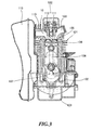
- Fig. 3 schematically shows a cross section taken along line I-I' in Fig. 2 .
- Fig. 4 schematically shows a cross section taken along line II-II' in Fig. 2 .
- an engine 100 of the present embodiment mainly includes a cylinder block 101, a crankcase 102, an oil case 103, and a cylinder head 10. These components are detachably mounted by coupling with each other with bolts.
- the cylinder block 101 and the cylinder head 10 are separated from one another to help to achieve high output, and an exhaust port 110 (described later) is provided in the cylinder head 10.
- the main body of the engine 100 is formed by the cylinder block 101, the crankcase 102, the oil case 103, and the cylinder head 10.
- a piston 104 is inserted in the cylinder block 101 to reciprocably move.
- the piston 104 can reciprocate in the cylinder block 101 by explosive power generated due to the combustion of mixed air in the combustion chamber 105 described later.
- a connecting rod 106 is pivotably connected to the piston 104.
- the connecting rod 106 converts the reciprocating motion of the piston 104 in the cylinder block 101 into the rotating motion of a crank shaft 107 described later.
- One end of the connecting rod 106 is connected pivotably to the piston 104.
- the other end of the connecting rod 106 is connected to a crank shaft 107.
- crank shaft 107 is connected to the piston 104 via the connecting rod 106. Accordingly, the reciprocating motion of the piston 104 is converted into the rotating motion of the crank shaft 107 via the connecting rod 106, and then transmitted to an output shaft.
- the crank shaft 107 is rotatably supported by the cylinder block 101 and the crankcase 102 which is provided on one end side (the lower side in Fig. 3 ) in the longitudinal direction of the cylinder block 101.
- crank chamber is formed in the crankcase 102. Both ends of the crank shaft 107 projecting from the crank chamber are sandwiched and rotatably supported between the cylinder block 101 and the crankcase 102.
- the cylinder block 101 constituting the main body of the engine 100 and a cooling fan 108 for sending cooling air to the cylinder head 10, are connected to the crank shaft 107.
- the cooling fan 108 rotates in conjunction with the rotation of the crank shaft 107, and sends cooling air in the radial direction and the axial direction of the crank shaft 107.
- the cooling fan 108 sends cooling air to the cylinder block 101 and the cylinder head 10 constituting the main body of the engine 100.
- the oil case 103 to store oil to be supplied to the crank chamber, is provided in the other end side of the crankcase 102 (the lower side in Fig. 1 to Fig. 4 ).
- the oil case 103 is formed as a housing which is surrounded on all four sides and the bottom and has an opening on the top.
- the inside of the oil case 103 surrounded on all four sides and the bottom serves as an oil reservoir.
- the semicircular portion of the crankcase 102 accommodating the crank shaft 107 where the crank shaft 107 can rotate, serves as a partition between the crank chamber and the oil reservoir.
- the cylinder head 10 is provided on the other end side of the cylinder block 101 (the upper part in Fig. 1 ).
- the cylinder block 101, the upper surface of the piston 104 and the cylinder head 10 form a combustion chamber 105.
- An intake port 109 is formed on the cylinder head 10.
- the intake port 109 communicates with a carburetor (not shown).
- An exhaust port 110 is formed on the cylinder head 10.
- the exhaust port 110 is in communication with a muffler 115.
- An intake valve 111 which opens and closes the intake port 109, is provided on the intake port 109.
- an exhaust valve 112 which opens and closes the exhaust port 110 is provided on the exhaust port 110.
- the intake valve III opens in an intake stroke over which the piston 104 moves from the top dead center to the bottom dead center. In the intake stroke, mixed air from the intake port 109 is mixed in the combustion chamber 105 due to the effect of the negative pressure generated by increasing the volume of the combustion chamber 105.
- the exhaust valve 112 opens during an exhaust stroke over which the piston 104 moves from the bottom dead center to the top dead center.
- exhaust stroke exhaust gas generated in the combustion chamber 105 is discharged from the exhaust port 110 to the muffler 115, due to the effect of the positive pressure generated by reducing the volume of the combustion chamber 105.
- a valve operating mechanism is connected to the intake valve III and the exhaust valve 112, which drives the intake valve 111 and the exhaust valve 112 to open and close the intake port 109 and the exhaust port 110.
- This valve operating mechanism is a so-called OHV type valve operating mechanism.
- the valve operating mechanism mainly includes a crank shaft gear, a cam shaft and a rocker arm 113. These crank shaft gear and cam shaft are provided in a side chamber which is formed along the cylinder block 101 and the crankcase 102. Meanwhile, the rocker arm 113 is provided in a valve operating chamber which is formed in the cylinder head 10.
- the crank shaft gear is disposed in the side chamber to rotate together with the crank shaft 107.
- the cam shaft gear is provided in the cam shaft.
- the cam shaft gear meshes with the crank shaft gear in the side chamber, and rotates the cam shaft with rotation which is half of the rotation of the crank shaft 107.
- a cam is provided on the cam shaft.
- the cam rotates together with the cam shaft.
- the one end of a push rod 114 contacts the cam, and the push rod 114 moves in the longitudinal direction along with the rotation of the cam.
- the other end of the push rod 114 is connected to the rocker arm 113, and the rocker arm 113 swings with the movement of the push rod 114. Then, the intake valve 111 and the exhaust valve 112 reciprocate along with the swing of the rocker arm 113. This allows the intake port 109 and the exhaust port 110 to open and close.
- the exhaust port 110 is formed on the cylinder head 10, and exhaust gas generated from the exhaust port 110 is discharged from the cylinder head 10 to the muffler 115.
- the muffler 115 is attached to the cylinder head 10 on which the exhaust port 110 opens.
- the muffler 115 is mounted by fitting fastening parts (not shown)into a first muffler mounting boss 16 and a second muffler mounting boss 17 which are muffler mounting bosses described later.
- the cylinder head 10 is a main component of the muffler mounting structure for mounting the muffler 115 to the engine 100 according to the present embodiment.
- Fig. 5 is a perspective view schematically showing from above the configuration of the cylinder head 10 of the engine 100 according to one embodiment of the present invention.
- Fig. 6 is a perspective view schematically showing from below the configuration of the cylinder head 10 of the engine 100 according to one embodiment of the present invention.
- Fig. 7 is a plan view schematically showing from above the configuration of the cylinder head 10 of the engine 100 according to one embodiment of the present invention.
- Fig. 8 schematically shows a cross section taken along line III-III' in Fig. 7 .
- the arrows shown in Fig. 8 illustrate the flows of cooling air send by the cooling fan 108.
- the intake port 109 is formed on the cylinder head 10.
- the intake port 109 is disposed in communication with the combustion chamber 105 as described above, and sucks in from the carburetor (not shown) to the combustion chamber 105.
- the exhaust port 110 is formed on the cylinder head 10.
- the exhaust port 110 is disposed in communication with the combustion chamber 105 as described above, and discharges the exhaust gas generated in the combustion chamber 105 to the muffler 115.
- a plurality of fins 20 are formed on the cylinder head 10. These fins 20 are disposed so as to cover the intake port 109 and the exhaust port 110, and send cooling air from the cooling fan 108 to the neighborhood of the intake port 109 and the exhaust port 110.
- These fins 20 stand in the same direction and are spaced from and parallel to each other. That is, the cooling air from the cooling fan 108 can cool the intake port 109 and the exhaust port 110 by flowing through the plurality of fins 20.
- an exhaust opening 12 of the exhaust port 110 is formed on the outermost fin 20a among the plurality of fins 20.
- the opening of the first muffler mounting boss 16 and the opening of the second muffler mounting boss 17 are formed on the fin 20a.
- the fastening parts to mount the muffler are fitted into the first muffler mounting boss 16 and the second muffler mounting boss 17.
- the fin 20a includes the opening of the first muffler mounting boss 16, the opening of the second muffler mounting boss 17, and the exhaust opening 12 on the same plane, and serves as a bearing surface to which the muffler is attached.
- the outermost fin 20a serves as a bearing surface to which the muffler is attached, and therefore there is no need to separately form a bearing surface on a place in the main body of the engine 100.
- the number of parts can be reduced because there is no need to separately form a bearing surface on a place in the main body of the engine 100.
- the first muffler mounting boss 16, the second muffler mounting boss 17, and the exhaust opening 12 of the exhaust port 110 slightly protrude from the surface of the fin 20a. By this means, it is possible to form a small gap between the bearing surface of the muffler and the fin 20a when the muffler is mounted. Therefore, it is possible to reduce the thermal conductivity from the muffler to the first muffler mounting boss 16 and the second muffler mounting boss 17.
- the exhaust port 110 of the present embodiment bridges between the outermost fin 20a and a fin 20b which is next to the fin 20a and penetrate the fin 20a and the fin 20b.
- first muffler mounting boss 16 and the second muffler mounting boss 17 bridge between the outermost fin 20a and the fin 20b which is next to the fin 20a. That is, the exhaust port 110, the first muffler mounting boss 16 and the second muffler mounting boss 17 bridge between the fin 20a and the fin 20b and are arranged in parallel with each other.
- first muffler mounting boss 16 and the second muffler mounting boss 17 bridge between the fin 20a and the fin 20b. Therefore, it is possible to improve the rigidity of the first muffler mounting boss 16 and the second muffler mounting boss 17.
- the first muffler mounting boss 16 is positioned in the more upstream side of cooling air than the exhaust port 110.
- the second muffler mounting boss 17 is positioned in the more downstream side of cooling air than the exhaust port 110.
- the cooling air sent from the cooling fan 108 flows into the space between the fin 20a and the fin 20b, and passes through the neighborhood of the first muffler mounting boss 16 to cool the first muffler mounting boss 16.
- the cooling air passes around the exhaust port 110 to cool the exhaust port 110. At this time, heat is generated because the cooling air passes around the exhaust port 110, and this heat increases the temperature of the cooling air.
- the cooling air whose temperature having increased passes through the neighborhood of the second muffler mounting boss 17 to cool the second muffler mounting boss 17.
- the first muffler mounting boss 16 and the second muffler mounting boss 17 are different in cooling efficiency with the cooling air from the cooling fan 108.
- the distance between the second muffler mounting boss 17, and a base part 10a of the cylinder head 10 and the exhaust port 110 is greater than the distance between the first muffler mounting boss 16 and those.
- the first muffler mounting boss 16 and the second muffler mounting boss 17 are different in cooling efficiency with the cooling air from the cooling fan 108, the distance between the second muffler mounting boss 17 and the base part 10a of the cylinder head 10 is greater than the distance between the first muffler mounting boss 16 and the base part 10a of the cylinder head 10. Therefore, the thermal conductivity from the combustion chamber 105 and the exhaust port 110 to the second muffler mounting boss is reduced. As a result of this, it is possible to reduce the difference in temperature between the first muffler mounting boss 16 and the second muffler mounting boss 17.
- the thermal conductivity from the combustion chamber 105 and the exhaust port 110 to the second muffler mounting boss 17 can be reduced. Also, the difference in temperature between the first muffler mounting boss 16 and the second muffler mounting boss 17 can be reduced. Therefore, it is possible to prevent the fastening parts from slackening.
- Fig. 9 is a cross-sectional view schematically showing the configuration of the cylinder head 80 of the engine according to another embodiment of the present invention, taken along line III-III' in Fig. 7 .
- the engine of the second embodiment is different from the engine of the above-described first embodiment in that, a first muffler mounting boss 86 is connected directly to a base part 80a of a cylinder head 80, and a second muffler mounting boss 87 is connected to the base part 80a of the cylinder head 80 via a fin 90a.
- the other components are the same as in the engine of the first embodiment.
- the same or equivalent components as in the first embodiment are assigned the same reference numerals, and overlapping descriptions will be omitted.
- the first muffler mounting boss 86 is connected directly to the base part 80a of the cylinder head 80, and the second muffler mounting boss 87 is connected to the base part 80a of the cylinder head 80 via the fin 90a, as described above.
- the engine 100 of the present embodiment has high output where the cylinder block 101 and the cylinder head 10 are separated from one another to help to achieve high output.
- This high-output engine 100 tends to increase in temperature at the combustion chamber 105 and the exhaust port 110. Therefore, the cooling efficiency with the present invention is especially effective for the engine 100.
- the engine 100 of the present embodiment is not limited to a configuration with high output where the cylinder block 101 and the cylinder head 10 are separated from one another, but another configuration is possible to produce the same effect where the cylinder block 101 and the cylinder head 10 are integrally formed.
- the engine 100 of the present embodiment is a four-stroke engine here
- the present invention is not limited to this, and, even when applied to a two-stroke engine, it is possible to produce the same effect, as long as the muffler mounting bosses to mount the muffler 115 to the main body of the engine 100 are apart from the exhaust port and there is a distance between the exhaust port and the muffler mounting bosses.
Landscapes
- Engineering & Computer Science (AREA)
- Chemical & Material Sciences (AREA)
- Combustion & Propulsion (AREA)
- Mechanical Engineering (AREA)
- General Engineering & Computer Science (AREA)
- Cylinder Crankcases Of Internal Combustion Engines (AREA)
- Motor Or Generator Frames (AREA)
- Exhaust Silencers (AREA)
Abstract
Description
- The present invention relates to an engine, and more particularly, relates to an engine configured to be able to prevent muffler mounting bolts to fix a muffler to an engine body, from slackening.
- Conventionally, as a muffler mounting structure for fixing a muffler to the engine body, a structure in which a muffler is fixed to the engine body with bolts, is generally known.
- In a muffler mounting structure disclosed, for example, in Japanese Patent Application Laid-Open No.
2007-2730 - In the muffler mounting structure of the engine described in the above-mentioned patent document, those muffler mounting bosses are provided nearby an exhaust port.
- Accordingly, there is a technical problem that the muffler mounting bosses tend to increase in the temperature, and therefore the fastening parts fitted into the muffler mounting bosses slacken by thermal expansion of the muffler mounting bosses.
- In view of the above-described problems, an object of the present invention is to provide an engine configured to be able to prevent fastening parts from slackening by reducing the thermal conductivity from a combustion chamber and an exhaust port to the muffler mounting bosses.
- An engine of the present invention includes a cylinder constituting a combustion chamber with a piston, an exhaust port configured to communicate with the combustion chamber, and a muffler mounted to an outlet of the exhaust port. The muffler is mounted with a muffler mounting boss into which a fixing part is fitted, and the muffler mounting boss is connected to a fin formed in the cylinder.
- The fin of the engine serves as a cooling fin for the cylinder.
- In the engine, a plurality of fins are formed in the cylinder, and the muffler mounting boss bridges between the plurality of fins.
- In the engine, the fin serves as a bearing surface to which the muffler is attached.
- The engine further includes a cooling fan configured to send cooling air. The muffler mounting boss includes a first muffler mounting boss and a second mounting boss, the first muffler mounting boss is positioned in a more upstream side of the cooling air than the exhaust port, and the second muffler mounting boss is positioned in a more downstream side of the cooling air than the exhaust port, and the first muffler mounting boss is connected directly to the cylinder, and the second muffler mounting boss is connected to the cylinder via the fin.
- The engine further includes a cooling fan configured to send cooling air. The muffler mounting boss includes a first muffler mounting boss and a second muffler mounting boss, the first muffler mounting boss is positioned in a more upstream side of the cooling air than the exhaust port, and the second muffler mounting boss is positioned in a more downstream side of the cooling air than the exhaust port, and a distance between the second muffler mounting boss and the cylinder is greater than a distance between the first muffler mounting boss and the cylinder.
- In the engine, the cylinder is configured to be able to be separated into a cylinder head and a cylinder block.
- With the engine according to the present invention, the muffler mounting bosses are connected to the cylinder via the fins, and therefore the thermal conductivity from the combustion chamber and the exhaust port to the muffler mounting bosses can be reduced. By this means, it is possible to prevent the fastening parts fitted into the muffler mounting bosses from slackening.
- In addition, with the engine according to the present invention, the plurality of fins are disposed in the cylinder, and the muffler mounting bosses bridge between the plurality of fins, and therefore are supported by the plurality of fins. As a result, the rigidity of the muffler mounting bosses can be improved. By this means, it is possible to prevent the muffler mounting bosses from being damaged.
- Moreover, with the engine according to the present invention, the fin serves as a bearing surface to which the muffler is attached, and therefore the muffler can be mounted without a separate seat plate. Hence, the number of parts can be reduced.
- Furthermore, with the engine according to the present invention, the first muffler mounting boss is connected directly to the cylinder, and the second muffler mounting boss is connected to the cylinder via the cooling fin which is cooled by cooling air where the first muffler mounting boss is positioned in the more upstream side of the cooling air than the exhaust port, and the second muffler mounting boss is positioned in the more downstream side of the cooling air than the exhaust port. As a result, the cooling efficiency of the second muffler mounting boss is improved. Therefore, the difference in temperature between the first muffler mounting boss and the second muffler mounting boss can be reduced.
- By this means, it is possible to equalize the thermal expansion rate of the fastening part fitted into the first muffler mounting boss and the thermal expansion rate of the fastening part fitted into the second muffler mounting boss. Therefore, it is possible to prevent the fastening parts from slackening.
- Furthermore, with the engine according to the present invention, the first muffler mounting boss and the second muffler mounting boss bridge between the plurality of fins which serve as cooling fins to cool the cylinder. Hence, the first muffler mounting boss and the second muffler mounting boss are cooled by the cooling air flowing through the plurality of cooling fins. In addition, the distance between the second muffler mounting boss and the cylinder is greater than the distance between the first muffler mounting boss and the cylinder. Therefore, in particular, cooling air flows smoothly around the second muffler mounting boss which tends to rise in temperature, so that the cooling efficiency is improved. Therefore, the difference in temperature between the first muffler mounting boss and the second muffler mounting boss can be reduced. By this means, it is possible to equalize the thermal expansion rate of the fastening part fitted into the first muffler mounting boss and the thermal expansion rate of the fastening part fitted into the second muffler mounting boss Therefore, it is possible to prevent the fastening parts from slackening.
-
-
Fig. 1 is a perspective view schematically showing the configuration of an engine according to one embodiment of the present invention; -
Fig. 2 is a plan view schematically showing the configuration of the engine according to one embodiment of the present invention; -
Fig. 3 schematically shows a cross section taken along line I-I' inFig. 2 ; -
Fig. 4 schematically shows a cross section taken along line II-II' inFig. 2 ; -
Fig. 5 is a perspective view schematically showing the configuration of a cylinder head of the engine according to one embodiment of the present invention; -
Fig. 6 is a perspective view schematically showing the configuration of the cylinder head of the engine according to one embodiment of the present invention; -
Fig. 7 is a plan view schematically showing the configuration of the cylinder head of the engine according to one embodiment of the present invention; -
Fig. 8 schematically shows a cross section taken along line III-III' inFig. 7 ; and -
Fig. 9 is a cross-sectional view schematically showing the cylinder head of the engine according to another embodiment of the present invention, taken along the line III-III' inFig. 7 . -
Fig. 1 is a perspective view schematically showing the configuration of anengine 100 according to one embodiment of the present invention.Fig. 2 is a plan view schematically showing the configuration of theengine 100 according to one embodiment of the present invention.Fig. 3 schematically shows a cross section taken along line I-I' inFig. 2 .Fig. 4 schematically shows a cross section taken along line II-II' inFig. 2 . - As shown in
Fig. 1 to Fig. 4 , anengine 100 of the present embodiment mainly includes acylinder block 101, acrankcase 102, anoil case 103, and acylinder head 10. These components are detachably mounted by coupling with each other with bolts. - Note that, in the
engine 100 of the present embodiment, thecylinder block 101 and thecylinder head 10 are separated from one another to help to achieve high output, and an exhaust port 110 (described later) is provided in thecylinder head 10. - The main body of the
engine 100 is formed by thecylinder block 101, thecrankcase 102, theoil case 103, and thecylinder head 10. Apiston 104 is inserted in thecylinder block 101 to reciprocably move. - The
piston 104 can reciprocate in thecylinder block 101 by explosive power generated due to the combustion of mixed air in thecombustion chamber 105 described later. A connectingrod 106 is pivotably connected to thepiston 104. - The connecting
rod 106 converts the reciprocating motion of thepiston 104 in thecylinder block 101 into the rotating motion of acrank shaft 107 described later. One end of the connectingrod 106 is connected pivotably to thepiston 104. The other end of the connectingrod 106 is connected to acrank shaft 107. - As described above, the
crank shaft 107 is connected to thepiston 104 via the connectingrod 106. Accordingly, the reciprocating motion of thepiston 104 is converted into the rotating motion of thecrank shaft 107 via the connectingrod 106, and then transmitted to an output shaft. - The
crank shaft 107 is rotatably supported by thecylinder block 101 and thecrankcase 102 which is provided on one end side (the lower side inFig. 3 ) in the longitudinal direction of thecylinder block 101. - Specifically, a crank chamber is formed in the
crankcase 102. Both ends of thecrank shaft 107 projecting from the crank chamber are sandwiched and rotatably supported between thecylinder block 101 and thecrankcase 102. - In addition to the output shaft, the
cylinder block 101 constituting the main body of theengine 100 and a coolingfan 108 for sending cooling air to thecylinder head 10, are connected to the crankshaft 107. - That is, the cooling
fan 108 rotates in conjunction with the rotation of thecrank shaft 107, and sends cooling air in the radial direction and the axial direction of thecrank shaft 107. In other words, the coolingfan 108 sends cooling air to thecylinder block 101 and thecylinder head 10 constituting the main body of theengine 100. - In addition, the
oil case 103 to store oil to be supplied to the crank chamber, is provided in the other end side of the crankcase 102 (the lower side inFig. 1 to Fig. 4 ). Theoil case 103 is formed as a housing which is surrounded on all four sides and the bottom and has an opening on the top. - The inside of the
oil case 103 surrounded on all four sides and the bottom serves as an oil reservoir. The semicircular portion of thecrankcase 102 accommodating thecrank shaft 107 where thecrank shaft 107 can rotate, serves as a partition between the crank chamber and the oil reservoir. - On the other hand, the
cylinder head 10 is provided on the other end side of the cylinder block 101 (the upper part inFig. 1 ). Thecylinder block 101, the upper surface of thepiston 104 and thecylinder head 10 form acombustion chamber 105. Anintake port 109 is formed on thecylinder head 10. Theintake port 109 communicates with a carburetor (not shown). - An
exhaust port 110 is formed on thecylinder head 10. Theexhaust port 110 is in communication with amuffler 115. Anintake valve 111 which opens and closes theintake port 109, is provided on theintake port 109. Additionally, anexhaust valve 112 which opens and closes theexhaust port 110 is provided on theexhaust port 110. - The intake valve III opens in an intake stroke over which the
piston 104 moves from the top dead center to the bottom dead center. In the intake stroke, mixed air from theintake port 109 is mixed in thecombustion chamber 105 due to the effect of the negative pressure generated by increasing the volume of thecombustion chamber 105. - Additionally, the
exhaust valve 112 opens during an exhaust stroke over which thepiston 104 moves from the bottom dead center to the top dead center. In the exhaust stroke, exhaust gas generated in thecombustion chamber 105 is discharged from theexhaust port 110 to themuffler 115, due to the effect of the positive pressure generated by reducing the volume of thecombustion chamber 105. - A valve operating mechanism is connected to the intake valve III and the
exhaust valve 112, which drives theintake valve 111 and theexhaust valve 112 to open and close theintake port 109 and theexhaust port 110. This valve operating mechanism is a so-called OHV type valve operating mechanism. - Specifically, the valve operating mechanism mainly includes a crank shaft gear, a cam shaft and a
rocker arm 113. These crank shaft gear and cam shaft are provided in a side chamber which is formed along thecylinder block 101 and thecrankcase 102. Meanwhile, therocker arm 113 is provided in a valve operating chamber which is formed in thecylinder head 10. - The crank shaft gear is disposed in the side chamber to rotate together with the
crank shaft 107. The cam shaft gear is provided in the cam shaft. The cam shaft gear meshes with the crank shaft gear in the side chamber, and rotates the cam shaft with rotation which is half of the rotation of thecrank shaft 107. - Moreover, a cam is provided on the cam shaft. The cam rotates together with the cam shaft. The one end of a
push rod 114 contacts the cam, and thepush rod 114 moves in the longitudinal direction along with the rotation of the cam. - Meanwhile, the other end of the
push rod 114 is connected to therocker arm 113, and therocker arm 113 swings with the movement of thepush rod 114. Then, theintake valve 111 and theexhaust valve 112 reciprocate along with the swing of therocker arm 113. This allows theintake port 109 and theexhaust port 110 to open and close. - As described above, with the present embodiment, the
exhaust port 110 is formed on thecylinder head 10, and exhaust gas generated from theexhaust port 110 is discharged from thecylinder head 10 to themuffler 115. - In the present embodiment, the
muffler 115 is attached to thecylinder head 10 on which theexhaust port 110 opens. In this case, themuffler 115 is mounted by fitting fastening parts (not shown)into a firstmuffler mounting boss 16 and a secondmuffler mounting boss 17 which are muffler mounting bosses described later. - Next, the
cylinder head 10 will be explained with reference toFig. 5 to Fig. 8 . Thecylinder head 10 is a main component of the muffler mounting structure for mounting themuffler 115 to theengine 100 according to the present embodiment. -
Fig. 5 is a perspective view schematically showing from above the configuration of thecylinder head 10 of theengine 100 according to one embodiment of the present invention.Fig. 6 is a perspective view schematically showing from below the configuration of thecylinder head 10 of theengine 100 according to one embodiment of the present invention.Fig. 7 is a plan view schematically showing from above the configuration of thecylinder head 10 of theengine 100 according to one embodiment of the present invention.Fig. 8 schematically shows a cross section taken along line III-III' inFig. 7 . Here, the arrows shown inFig. 8 illustrate the flows of cooling air send by the coolingfan 108. - As shown in
Fig. 5 to Fig. 8 , theintake port 109 is formed on thecylinder head 10. Theintake port 109 is disposed in communication with thecombustion chamber 105 as described above, and sucks in from the carburetor (not shown) to thecombustion chamber 105. - In addition, the
exhaust port 110 is formed on thecylinder head 10. Theexhaust port 110 is disposed in communication with thecombustion chamber 105 as described above, and discharges the exhaust gas generated in thecombustion chamber 105 to themuffler 115. - A plurality of
fins 20 are formed on thecylinder head 10. Thesefins 20 are disposed so as to cover theintake port 109 and theexhaust port 110, and send cooling air from the coolingfan 108 to the neighborhood of theintake port 109 and theexhaust port 110. - These
fins 20 stand in the same direction and are spaced from and parallel to each other. That is, the cooling air from the coolingfan 108 can cool theintake port 109 and theexhaust port 110 by flowing through the plurality offins 20. - In the present embodiment, an
exhaust opening 12 of theexhaust port 110 is formed on theoutermost fin 20a among the plurality offins 20. The opening of the firstmuffler mounting boss 16 and the opening of the secondmuffler mounting boss 17 are formed on thefin 20a. The fastening parts to mount the muffler are fitted into the firstmuffler mounting boss 16 and the secondmuffler mounting boss 17. - The
fin 20a includes the opening of the firstmuffler mounting boss 16, the opening of the secondmuffler mounting boss 17, and theexhaust opening 12 on the same plane, and serves as a bearing surface to which the muffler is attached. - In this way, the
outermost fin 20a serves as a bearing surface to which the muffler is attached, and therefore there is no need to separately form a bearing surface on a place in the main body of theengine 100. Hence, it is possible to simplify the configuration of the mold for the main body of theengine 100. Moreover, the number of parts can be reduced because there is no need to separately form a bearing surface on a place in the main body of theengine 100. - The first
muffler mounting boss 16, the secondmuffler mounting boss 17, and theexhaust opening 12 of theexhaust port 110 slightly protrude from the surface of thefin 20a. By this means, it is possible to form a small gap between the bearing surface of the muffler and thefin 20a when the muffler is mounted. Therefore, it is possible to reduce the thermal conductivity from the muffler to the firstmuffler mounting boss 16 and the secondmuffler mounting boss 17. - As described above, the
exhaust port 110 of the present embodiment bridges between theoutermost fin 20a and afin 20b which is next to thefin 20a and penetrate thefin 20a and thefin 20b. - Also, the first
muffler mounting boss 16 and the secondmuffler mounting boss 17 bridge between theoutermost fin 20a and thefin 20b which is next to thefin 20a. That is, theexhaust port 110, the firstmuffler mounting boss 16 and the secondmuffler mounting boss 17 bridge between thefin 20a and thefin 20b and are arranged in parallel with each other. - In this way, the first
muffler mounting boss 16 and the secondmuffler mounting boss 17 bridge between thefin 20a and thefin 20b. Therefore, it is possible to improve the rigidity of the firstmuffler mounting boss 16 and the secondmuffler mounting boss 17. - In the present embodiment, the first
muffler mounting boss 16 is positioned in the more upstream side of cooling air than theexhaust port 110. Meanwhile, the secondmuffler mounting boss 17 is positioned in the more downstream side of cooling air than theexhaust port 110. - Here, the cooling air sent from the cooling
fan 108 flows into the space between thefin 20a and thefin 20b, and passes through the neighborhood of the firstmuffler mounting boss 16 to cool the firstmuffler mounting boss 16. - Then, the cooling air passes around the
exhaust port 110 to cool theexhaust port 110. At this time, heat is generated because the cooling air passes around theexhaust port 110, and this heat increases the temperature of the cooling air. - Then, the cooling air whose temperature having increased passes through the neighborhood of the second
muffler mounting boss 17 to cool the secondmuffler mounting boss 17. By this means, the firstmuffler mounting boss 16 and the secondmuffler mounting boss 17 are different in cooling efficiency with the cooling air from the coolingfan 108. - In this way, taking into account the first
muffler mounting boss 16 and the secondmuffler mounting boss 17 are different in cooling efficiency, the distance between the secondmuffler mounting boss 17, and abase part 10a of thecylinder head 10 and theexhaust port 110 is greater than the distance between the firstmuffler mounting boss 16 and those. - Accordingly, it is possible to make the thermal conductivity from the
base part 10a of thecylinder head 10 and theexhaust port 110 to the secondmuffler mounting boss 17 lower than the thermal conductivity from thebase part 10a of thecylinder head 10 and theexhaust port 110 to the firstmuffler mounting boss 16 to improve the cooling efficiency of the secondmuffler mounting boss 17. Therefore, it is possible to prevent the fastening parts fitted into thesecond muffler boss 17 from slackening. - Although the first
muffler mounting boss 16 and the secondmuffler mounting boss 17 are different in cooling efficiency with the cooling air from the coolingfan 108, the distance between the secondmuffler mounting boss 17 and thebase part 10a of thecylinder head 10 is greater than the distance between the firstmuffler mounting boss 16 and thebase part 10a of thecylinder head 10. Therefore, the thermal conductivity from thecombustion chamber 105 and theexhaust port 110 to the second muffler mounting boss is reduced. As a result of this, it is possible to reduce the difference in temperature between the firstmuffler mounting boss 16 and the secondmuffler mounting boss 17. - As described above, with the present embodiment, the thermal conductivity from the
combustion chamber 105 and theexhaust port 110 to the secondmuffler mounting boss 17 can be reduced. Also, the difference in temperature between the firstmuffler mounting boss 16 and the secondmuffler mounting boss 17 can be reduced. Therefore, it is possible to prevent the fastening parts from slackening. - Next, the engine of the second embodiment will be described with reference to
Fig. 9. Fig. 9 is a cross-sectional view schematically showing the configuration of thecylinder head 80 of the engine according to another embodiment of the present invention, taken along line III-III' inFig. 7 . - Here, the engine of the second embodiment is different from the engine of the above-described first embodiment in that, a first
muffler mounting boss 86 is connected directly to abase part 80a of acylinder head 80, and a secondmuffler mounting boss 87 is connected to thebase part 80a of thecylinder head 80 via a fin 90a. The other components are the same as in the engine of the first embodiment. The same or equivalent components as in the first embodiment are assigned the same reference numerals, and overlapping descriptions will be omitted. - As shown in
Fig. 9 , in thecylinder head 80 of the present embodiment, the firstmuffler mounting boss 86 is connected directly to thebase part 80a of thecylinder head 80, and the secondmuffler mounting boss 87 is connected to thebase part 80a of thecylinder head 80 via the fin 90a, as described above. - Therefore, it is possible to reduce the difference in temperature between the first
muffler mounting boss 86 and the secondmuffler mounting boss 87 where the firstmuffler mounting boss 86 is positioned in the more upstream side of cooling air than theexhaust port 110 and the secondmuffler mounting boss 87 is positioned in the more downstream side of cooling air than theexhaust port 110. By this means, it is possible to equalize the thermal expansion rate of the fastening part fitted into the firstmuffler mounting boss 86 and the thermal expansion rate of the fastening part fitted into the secondmuffler mounting boss 87 to prevent the fastening parts from slackening. - As described above, the
engine 100 of the present embodiment has high output where thecylinder block 101 and thecylinder head 10 are separated from one another to help to achieve high output. This high-output engine 100 tends to increase in temperature at thecombustion chamber 105 and theexhaust port 110. Therefore, the cooling efficiency with the present invention is especially effective for theengine 100. - The
engine 100 of the present embodiment is not limited to a configuration with high output where thecylinder block 101 and thecylinder head 10 are separated from one another, but another configuration is possible to produce the same effect where thecylinder block 101 and thecylinder head 10 are integrally formed. - In addition, although the
engine 100 of the present embodiment is a four-stroke engine here, the present invention is not limited to this, and, even when applied to a two-stroke engine, it is possible to produce the same effect, as long as the muffler mounting bosses to mount themuffler 115 to the main body of theengine 100 are apart from the exhaust port and there is a distance between the exhaust port and the muffler mounting bosses.
Claims (7)
- An engine comprising:a cylinder constituting a combustion chamber with a piston;an exhaust port configured to communicate with the combustion chamber; anda muffler mounted to an outlet of the exhaust port, wherein:the muffler is mounted with a muffler mounting boss into which a fixing part is fitted; andthe muffler mounting boss is connected to a fin formed in the cylinder.
- The engine according to claim 1, wherein the fin serves as a cooling fin for the cylinder.
- The engine according to claim 2, wherein a plurality of fins are formed in the cylinder, and the muffler mounting boss bridges between the plurality of fins.
- The engine according to any one of claims 1 to 3, wherein the fin serves as a bearing surface to which the muffler is attached.
- The engine according to any one of claims 2 to 4, further comprising a cooling fan configured to send cooling air, wherein:the muffler mounting boss includes a first muffler mounting boss and a second mounting boss, the first muffler mounting boss being positioned in a more upstream side of the cooling air than the exhaust port, and the second muffler mounting boss being positioned in a more downstream side of the cooling air than the exhaust port; andthe first muffler mounting boss is connected directly to the cylinder, and the second muffler mounting boss is connected to the cylinder via the fin.
- The engine according to any one of claims 3 and 4, further comprising a cooling fan configured to send cooling air, wherein:the muffler mounting boss includes a first muffler mounting boss and a second muffler mounting boss, the first muffler mounting boss being positioned in a more upstream side of the cooling air than the exhaust port, and the second muffler mounting boss being positioned in a more downstream side of the cooling air than the exhaust port; anda distance between the second muffler mounting boss and the cylinder is greater than a distance between the first muffler mounting boss and the cylinder.
- The engine according to any one of claims 1 to 6, wherein the cylinder is configured to be able to be separated into a cylinder head and a cylinder block.
Applications Claiming Priority (1)
| Application Number | Priority Date | Filing Date | Title |
|---|---|---|---|
| JP2010244751A JP5624850B2 (en) | 2010-10-29 | 2010-10-29 | engine |
Publications (2)
| Publication Number | Publication Date |
|---|---|
| EP2447496A1 true EP2447496A1 (en) | 2012-05-02 |
| EP2447496B1 EP2447496B1 (en) | 2015-07-29 |
Family
ID=44936184
Family Applications (1)
| Application Number | Title | Priority Date | Filing Date |
|---|---|---|---|
| EP11186000.3A Active EP2447496B1 (en) | 2010-10-29 | 2011-10-20 | Muffler mounting structure for an internal combustion engine |
Country Status (4)
| Country | Link |
|---|---|
| US (1) | US8439157B2 (en) |
| EP (1) | EP2447496B1 (en) |
| JP (1) | JP5624850B2 (en) |
| CN (1) | CN102465749B (en) |
Families Citing this family (1)
| Publication number | Priority date | Publication date | Assignee | Title |
|---|---|---|---|---|
| US9382870B2 (en) | 2013-10-08 | 2016-07-05 | Ford Global Technologies, Llc | Compression boss for engine front cover |
Citations (5)
| Publication number | Priority date | Publication date | Assignee | Title |
|---|---|---|---|---|
| FR2708043A1 (en) * | 1994-07-18 | 1995-01-27 | Wci Outdoor Products Inc | Two-stroke air-cooled, fuel-fired, air-cooled engine to power a portable tool. |
| CN2309427Y (en) * | 1997-08-01 | 1999-03-03 | 宝马机车引擎研发企业股份有限公司 | Cooling device for air-cooled OHV engine cylinder head |
| JP2007002730A (en) | 2005-06-23 | 2007-01-11 | Honda Motor Co Ltd | General-purpose engine muffler structure |
| CN201144736Y (en) * | 2008-01-22 | 2008-11-05 | 重庆润通动力有限公司 | Air-cooled type universal engine cylinder head |
| WO2011011260A1 (en) * | 2009-07-23 | 2011-01-27 | Briggs & Stratton Corporation | Muffler attachment system |
Family Cites Families (8)
| Publication number | Priority date | Publication date | Assignee | Title |
|---|---|---|---|---|
| JPS5744926U (en) * | 1980-08-29 | 1982-03-12 | ||
| JPS6351140U (en) * | 1986-09-22 | 1988-04-06 | ||
| DE4303127B4 (en) * | 1993-02-04 | 2006-10-05 | Fa. Andreas Stihl | Internal combustion engine |
| US5383427A (en) * | 1993-07-19 | 1995-01-24 | Wci Outdoor Products, Inc. | Two-cycle, air-cooled uniflow gasoline engine for powering a portable tool |
| DE19924888B4 (en) * | 1999-06-01 | 2013-07-11 | Andreas Stihl Ag & Co. | Exhaust silencer for internal combustion engines |
| DE10304326A1 (en) * | 2003-02-04 | 2004-08-12 | Andreas Stihl Ag & Co. Kg | muffler assembly |
| MY148994A (en) * | 2005-06-23 | 2013-06-28 | Honda Motor Co Ltd | Muffler unit for general-purpose engine |
| US20100083512A1 (en) * | 2008-10-06 | 2010-04-08 | Husqvarna Zenoah Co., Ltd. | Chain saw |
-
2010
- 2010-10-29 JP JP2010244751A patent/JP5624850B2/en active Active
-
2011
- 2011-08-31 CN CN201110258746.9A patent/CN102465749B/en not_active Expired - Fee Related
- 2011-10-18 US US13/275,732 patent/US8439157B2/en active Active
- 2011-10-20 EP EP11186000.3A patent/EP2447496B1/en active Active
Patent Citations (5)
| Publication number | Priority date | Publication date | Assignee | Title |
|---|---|---|---|---|
| FR2708043A1 (en) * | 1994-07-18 | 1995-01-27 | Wci Outdoor Products Inc | Two-stroke air-cooled, fuel-fired, air-cooled engine to power a portable tool. |
| CN2309427Y (en) * | 1997-08-01 | 1999-03-03 | 宝马机车引擎研发企业股份有限公司 | Cooling device for air-cooled OHV engine cylinder head |
| JP2007002730A (en) | 2005-06-23 | 2007-01-11 | Honda Motor Co Ltd | General-purpose engine muffler structure |
| CN201144736Y (en) * | 2008-01-22 | 2008-11-05 | 重庆润通动力有限公司 | Air-cooled type universal engine cylinder head |
| WO2011011260A1 (en) * | 2009-07-23 | 2011-01-27 | Briggs & Stratton Corporation | Muffler attachment system |
Also Published As
| Publication number | Publication date |
|---|---|
| CN102465749B (en) | 2014-05-07 |
| CN102465749A (en) | 2012-05-23 |
| JP2012097619A (en) | 2012-05-24 |
| US20120103720A1 (en) | 2012-05-03 |
| JP5624850B2 (en) | 2014-11-12 |
| EP2447496B1 (en) | 2015-07-29 |
| US8439157B2 (en) | 2013-05-14 |
Similar Documents
| Publication | Publication Date | Title |
|---|---|---|
| US7201132B2 (en) | Combustion engine of vertical shaft type | |
| EP2112360B1 (en) | Monolithic block and valve train for a four-stroke engine | |
| JP6476796B2 (en) | Oil passage structure for cooling of multi-cylinder engines | |
| EP1965051A1 (en) | Engine assembly with variable stroke characteristics | |
| CN101175911A (en) | two stroke engine | |
| CN100453790C (en) | general engine | |
| TW554131B (en) | Oil pump mounting structure | |
| EP2447496B1 (en) | Muffler mounting structure for an internal combustion engine | |
| US20070169726A1 (en) | Portable 4-cycle engine and portable machine equipped with the 4-cycle engine | |
| JP4341081B2 (en) | Two-cycle internal combustion engine and its cylinder | |
| JP2015034532A (en) | Engine cylinder head | |
| JP5013615B2 (en) | Engine cylinder cooling structure | |
| JP2005140170A (en) | Two-cycle engine | |
| JP4007885B2 (en) | Air pump drive | |
| JP4647860B2 (en) | Inclined cylinder type general-purpose four-cycle engine | |
| JP3445744B2 (en) | Cylinder head cooling system for overhead valve type engine | |
| JP2018204579A (en) | Oil passage structure for cooling engine | |
| JP2013245577A (en) | cylinder head | |
| JPS609364Y2 (en) | engine lubrication system | |
| JP4477537B2 (en) | Monoblock engine | |
| JP4636551B2 (en) | Backpack type air blower equipped with 4-cycle engine | |
| JP4422110B2 (en) | Portable 4-cycle engine | |
| JP5804710B2 (en) | Cylinder block structure | |
| JP6897347B2 (en) | Engine cooling oil passage structure | |
| JP2012177309A (en) | 4-stroke engine |
Legal Events
| Date | Code | Title | Description |
|---|---|---|---|
| PUAI | Public reference made under article 153(3) epc to a published international application that has entered the european phase |
Free format text: ORIGINAL CODE: 0009012 |
|
| AK | Designated contracting states |
Kind code of ref document: A1 Designated state(s): AL AT BE BG CH CY CZ DE DK EE ES FI FR GB GR HR HU IE IS IT LI LT LU LV MC MK MT NL NO PL PT RO RS SE SI SK SM TR |
|
| AX | Request for extension of the european patent |
Extension state: BA ME |
|
| 17P | Request for examination filed |
Effective date: 20121102 |
|
| RIC1 | Information provided on ipc code assigned before grant |
Ipc: F01N 13/18 20100101AFI20150129BHEP Ipc: F01N 13/00 20100101ALI20150129BHEP Ipc: F01N 1/08 20060101ALI20150129BHEP |
|
| GRAP | Despatch of communication of intention to grant a patent |
Free format text: ORIGINAL CODE: EPIDOSNIGR1 |
|
| INTG | Intention to grant announced |
Effective date: 20150319 |
|
| GRAS | Grant fee paid |
Free format text: ORIGINAL CODE: EPIDOSNIGR3 |
|
| GRAA | (expected) grant |
Free format text: ORIGINAL CODE: 0009210 |
|
| AK | Designated contracting states |
Kind code of ref document: B1 Designated state(s): AL AT BE BG CH CY CZ DE DK EE ES FI FR GB GR HR HU IE IS IT LI LT LU LV MC MK MT NL NO PL PT RO RS SE SI SK SM TR |
|
| REG | Reference to a national code |
Ref country code: GB Ref legal event code: FG4D |
|
| REG | Reference to a national code |
Ref country code: CH Ref legal event code: EP |
|
| REG | Reference to a national code |
Ref country code: AT Ref legal event code: REF Ref document number: 739489 Country of ref document: AT Kind code of ref document: T Effective date: 20150815 |
|
| REG | Reference to a national code |
Ref country code: IE Ref legal event code: FG4D |
|
| REG | Reference to a national code |
Ref country code: DE Ref legal event code: R096 Ref document number: 602011018177 Country of ref document: DE |
|
| REG | Reference to a national code |
Ref country code: AT Ref legal event code: MK05 Ref document number: 739489 Country of ref document: AT Kind code of ref document: T Effective date: 20150729 |
|
| REG | Reference to a national code |
Ref country code: LT Ref legal event code: MG4D |
|
| REG | Reference to a national code |
Ref country code: NL Ref legal event code: MP Effective date: 20150729 |
|
| PG25 | Lapsed in a contracting state [announced via postgrant information from national office to epo] |
Ref country code: FI Free format text: LAPSE BECAUSE OF FAILURE TO SUBMIT A TRANSLATION OF THE DESCRIPTION OR TO PAY THE FEE WITHIN THE PRESCRIBED TIME-LIMIT Effective date: 20150729 Ref country code: GR Free format text: LAPSE BECAUSE OF FAILURE TO SUBMIT A TRANSLATION OF THE DESCRIPTION OR TO PAY THE FEE WITHIN THE PRESCRIBED TIME-LIMIT Effective date: 20151030 Ref country code: LT Free format text: LAPSE BECAUSE OF FAILURE TO SUBMIT A TRANSLATION OF THE DESCRIPTION OR TO PAY THE FEE WITHIN THE PRESCRIBED TIME-LIMIT Effective date: 20150729 Ref country code: LV Free format text: LAPSE BECAUSE OF FAILURE TO SUBMIT A TRANSLATION OF THE DESCRIPTION OR TO PAY THE FEE WITHIN THE PRESCRIBED TIME-LIMIT Effective date: 20150729 Ref country code: NO Free format text: LAPSE BECAUSE OF FAILURE TO SUBMIT A TRANSLATION OF THE DESCRIPTION OR TO PAY THE FEE WITHIN THE PRESCRIBED TIME-LIMIT Effective date: 20151029 |
|
| PG25 | Lapsed in a contracting state [announced via postgrant information from national office to epo] |
Ref country code: PL Free format text: LAPSE BECAUSE OF FAILURE TO SUBMIT A TRANSLATION OF THE DESCRIPTION OR TO PAY THE FEE WITHIN THE PRESCRIBED TIME-LIMIT Effective date: 20150729 Ref country code: HR Free format text: LAPSE BECAUSE OF FAILURE TO SUBMIT A TRANSLATION OF THE DESCRIPTION OR TO PAY THE FEE WITHIN THE PRESCRIBED TIME-LIMIT Effective date: 20150729 Ref country code: PT Free format text: LAPSE BECAUSE OF FAILURE TO SUBMIT A TRANSLATION OF THE DESCRIPTION OR TO PAY THE FEE WITHIN THE PRESCRIBED TIME-LIMIT Effective date: 20151130 Ref country code: IS Free format text: LAPSE BECAUSE OF FAILURE TO SUBMIT A TRANSLATION OF THE DESCRIPTION OR TO PAY THE FEE WITHIN THE PRESCRIBED TIME-LIMIT Effective date: 20151129 Ref country code: SE Free format text: LAPSE BECAUSE OF FAILURE TO SUBMIT A TRANSLATION OF THE DESCRIPTION OR TO PAY THE FEE WITHIN THE PRESCRIBED TIME-LIMIT Effective date: 20150729 Ref country code: RS Free format text: LAPSE BECAUSE OF FAILURE TO SUBMIT A TRANSLATION OF THE DESCRIPTION OR TO PAY THE FEE WITHIN THE PRESCRIBED TIME-LIMIT Effective date: 20150729 Ref country code: AT Free format text: LAPSE BECAUSE OF FAILURE TO SUBMIT A TRANSLATION OF THE DESCRIPTION OR TO PAY THE FEE WITHIN THE PRESCRIBED TIME-LIMIT Effective date: 20150729 Ref country code: ES Free format text: LAPSE BECAUSE OF FAILURE TO SUBMIT A TRANSLATION OF THE DESCRIPTION OR TO PAY THE FEE WITHIN THE PRESCRIBED TIME-LIMIT Effective date: 20150729 |
|
| PG25 | Lapsed in a contracting state [announced via postgrant information from national office to epo] |
Ref country code: NL Free format text: LAPSE BECAUSE OF FAILURE TO SUBMIT A TRANSLATION OF THE DESCRIPTION OR TO PAY THE FEE WITHIN THE PRESCRIBED TIME-LIMIT Effective date: 20150729 |
|
| PG25 | Lapsed in a contracting state [announced via postgrant information from national office to epo] |
Ref country code: DK Free format text: LAPSE BECAUSE OF FAILURE TO SUBMIT A TRANSLATION OF THE DESCRIPTION OR TO PAY THE FEE WITHIN THE PRESCRIBED TIME-LIMIT Effective date: 20150729 Ref country code: SK Free format text: LAPSE BECAUSE OF FAILURE TO SUBMIT A TRANSLATION OF THE DESCRIPTION OR TO PAY THE FEE WITHIN THE PRESCRIBED TIME-LIMIT Effective date: 20150729 Ref country code: CZ Free format text: LAPSE BECAUSE OF FAILURE TO SUBMIT A TRANSLATION OF THE DESCRIPTION OR TO PAY THE FEE WITHIN THE PRESCRIBED TIME-LIMIT Effective date: 20150729 Ref country code: EE Free format text: LAPSE BECAUSE OF FAILURE TO SUBMIT A TRANSLATION OF THE DESCRIPTION OR TO PAY THE FEE WITHIN THE PRESCRIBED TIME-LIMIT Effective date: 20150729 Ref country code: IT Free format text: LAPSE BECAUSE OF FAILURE TO SUBMIT A TRANSLATION OF THE DESCRIPTION OR TO PAY THE FEE WITHIN THE PRESCRIBED TIME-LIMIT Effective date: 20150729 |
|
| REG | Reference to a national code |
Ref country code: DE Ref legal event code: R097 Ref document number: 602011018177 Country of ref document: DE |
|
| PG25 | Lapsed in a contracting state [announced via postgrant information from national office to epo] |
Ref country code: LU Free format text: LAPSE BECAUSE OF FAILURE TO SUBMIT A TRANSLATION OF THE DESCRIPTION OR TO PAY THE FEE WITHIN THE PRESCRIBED TIME-LIMIT Effective date: 20151020 Ref country code: RO Free format text: LAPSE BECAUSE OF FAILURE TO SUBMIT A TRANSLATION OF THE DESCRIPTION OR TO PAY THE FEE WITHIN THE PRESCRIBED TIME-LIMIT Effective date: 20150729 |
|
| REG | Reference to a national code |
Ref country code: CH Ref legal event code: PL |
|
| PLBE | No opposition filed within time limit |
Free format text: ORIGINAL CODE: 0009261 |
|
| STAA | Information on the status of an ep patent application or granted ep patent |
Free format text: STATUS: NO OPPOSITION FILED WITHIN TIME LIMIT |
|
| GBPC | Gb: european patent ceased through non-payment of renewal fee |
Effective date: 20151029 |
|
| PG25 | Lapsed in a contracting state [announced via postgrant information from national office to epo] |
Ref country code: MC Free format text: LAPSE BECAUSE OF FAILURE TO SUBMIT A TRANSLATION OF THE DESCRIPTION OR TO PAY THE FEE WITHIN THE PRESCRIBED TIME-LIMIT Effective date: 20150729 |
|
| 26N | No opposition filed |
Effective date: 20160502 |
|
| REG | Reference to a national code |
Ref country code: IE Ref legal event code: MM4A |
|
| PG25 | Lapsed in a contracting state [announced via postgrant information from national office to epo] |
Ref country code: GB Free format text: LAPSE BECAUSE OF NON-PAYMENT OF DUE FEES Effective date: 20151029 Ref country code: CH Free format text: LAPSE BECAUSE OF NON-PAYMENT OF DUE FEES Effective date: 20151031 Ref country code: LI Free format text: LAPSE BECAUSE OF NON-PAYMENT OF DUE FEES Effective date: 20151031 |
|
| REG | Reference to a national code |
Ref country code: FR Ref legal event code: ST Effective date: 20160630 |
|
| PG25 | Lapsed in a contracting state [announced via postgrant information from national office to epo] |
Ref country code: SI Free format text: LAPSE BECAUSE OF FAILURE TO SUBMIT A TRANSLATION OF THE DESCRIPTION OR TO PAY THE FEE WITHIN THE PRESCRIBED TIME-LIMIT Effective date: 20150729 Ref country code: FR Free format text: LAPSE BECAUSE OF NON-PAYMENT OF DUE FEES Effective date: 20151102 |
|
| PG25 | Lapsed in a contracting state [announced via postgrant information from national office to epo] |
Ref country code: IE Free format text: LAPSE BECAUSE OF NON-PAYMENT OF DUE FEES Effective date: 20151020 |
|
| PG25 | Lapsed in a contracting state [announced via postgrant information from national office to epo] |
Ref country code: BE Free format text: LAPSE BECAUSE OF FAILURE TO SUBMIT A TRANSLATION OF THE DESCRIPTION OR TO PAY THE FEE WITHIN THE PRESCRIBED TIME-LIMIT Effective date: 20150729 |
|
| PG25 | Lapsed in a contracting state [announced via postgrant information from national office to epo] |
Ref country code: HU Free format text: LAPSE BECAUSE OF FAILURE TO SUBMIT A TRANSLATION OF THE DESCRIPTION OR TO PAY THE FEE WITHIN THE PRESCRIBED TIME-LIMIT; INVALID AB INITIO Effective date: 20111020 Ref country code: BG Free format text: LAPSE BECAUSE OF FAILURE TO SUBMIT A TRANSLATION OF THE DESCRIPTION OR TO PAY THE FEE WITHIN THE PRESCRIBED TIME-LIMIT Effective date: 20150729 Ref country code: SM Free format text: LAPSE BECAUSE OF FAILURE TO SUBMIT A TRANSLATION OF THE DESCRIPTION OR TO PAY THE FEE WITHIN THE PRESCRIBED TIME-LIMIT Effective date: 20150729 |
|
| PG25 | Lapsed in a contracting state [announced via postgrant information from national office to epo] |
Ref country code: CY Free format text: LAPSE BECAUSE OF FAILURE TO SUBMIT A TRANSLATION OF THE DESCRIPTION OR TO PAY THE FEE WITHIN THE PRESCRIBED TIME-LIMIT Effective date: 20150729 |
|
| PG25 | Lapsed in a contracting state [announced via postgrant information from national office to epo] |
Ref country code: TR Free format text: LAPSE BECAUSE OF FAILURE TO SUBMIT A TRANSLATION OF THE DESCRIPTION OR TO PAY THE FEE WITHIN THE PRESCRIBED TIME-LIMIT Effective date: 20150729 Ref country code: MT Free format text: LAPSE BECAUSE OF FAILURE TO SUBMIT A TRANSLATION OF THE DESCRIPTION OR TO PAY THE FEE WITHIN THE PRESCRIBED TIME-LIMIT Effective date: 20150729 |
|
| PG25 | Lapsed in a contracting state [announced via postgrant information from national office to epo] |
Ref country code: MK Free format text: LAPSE BECAUSE OF FAILURE TO SUBMIT A TRANSLATION OF THE DESCRIPTION OR TO PAY THE FEE WITHIN THE PRESCRIBED TIME-LIMIT Effective date: 20150729 |
|
| PG25 | Lapsed in a contracting state [announced via postgrant information from national office to epo] |
Ref country code: AL Free format text: LAPSE BECAUSE OF FAILURE TO SUBMIT A TRANSLATION OF THE DESCRIPTION OR TO PAY THE FEE WITHIN THE PRESCRIBED TIME-LIMIT Effective date: 20150729 |
|
| REG | Reference to a national code |
Ref country code: DE Ref legal event code: R081 Ref document number: 602011018177 Country of ref document: DE Owner name: MARUYAMA MFG. CO., INC., JP Free format text: FORMER OWNER: MAKITA CORPORATION, AICHI, JP |
|
| PGFP | Annual fee paid to national office [announced via postgrant information from national office to epo] |
Ref country code: DE Payment date: 20250909 Year of fee payment: 15 |