EP2447158A2 - Aircraft cowl including a means for limiting magnetic scoop phenomena - Google Patents
Aircraft cowl including a means for limiting magnetic scoop phenomena Download PDFInfo
- Publication number
- EP2447158A2 EP2447158A2 EP20110306374 EP11306374A EP2447158A2 EP 2447158 A2 EP2447158 A2 EP 2447158A2 EP 20110306374 EP20110306374 EP 20110306374 EP 11306374 A EP11306374 A EP 11306374A EP 2447158 A2 EP2447158 A2 EP 2447158A2
- Authority
- EP
- European Patent Office
- Prior art keywords
- nacelle
- cover
- elements
- aircraft
- electromagnetic torque
- Prior art date
- Legal status (The legal status is an assumption and is not a legal conclusion. Google has not performed a legal analysis and makes no representation as to the accuracy of the status listed.)
- Withdrawn
Links
- 239000008188 pellet Substances 0.000 claims abstract description 10
- 238000011144 upstream manufacturing Methods 0.000 claims description 23
- 239000000696 magnetic material Substances 0.000 claims description 3
- 239000003351 stiffener Substances 0.000 description 4
- 210000003660 reticulum Anatomy 0.000 description 3
- 238000002485 combustion reaction Methods 0.000 description 1
- 230000000295 complement effect Effects 0.000 description 1
- 230000005611 electricity Effects 0.000 description 1
- 239000000446 fuel Substances 0.000 description 1
- 239000007789 gas Substances 0.000 description 1
- 238000012423 maintenance Methods 0.000 description 1
- 239000000463 material Substances 0.000 description 1
- 230000002787 reinforcement Effects 0.000 description 1
- 230000035939 shock Effects 0.000 description 1
Images


Classifications
-
- B—PERFORMING OPERATIONS; TRANSPORTING
- B64—AIRCRAFT; AVIATION; COSMONAUTICS
- B64D—EQUIPMENT FOR FITTING IN OR TO AIRCRAFT; FLIGHT SUITS; PARACHUTES; ARRANGEMENT OR MOUNTING OF POWER PLANTS OR PROPULSION TRANSMISSIONS IN AIRCRAFT
- B64D29/00—Power-plant nacelles, fairings, or cowlings
- B64D29/06—Attaching of nacelles, fairings or cowlings
-
- B—PERFORMING OPERATIONS; TRANSPORTING
- B64—AIRCRAFT; AVIATION; COSMONAUTICS
- B64D—EQUIPMENT FOR FITTING IN OR TO AIRCRAFT; FLIGHT SUITS; PARACHUTES; ARRANGEMENT OR MOUNTING OF POWER PLANTS OR PROPULSION TRANSMISSIONS IN AIRCRAFT
- B64D29/00—Power-plant nacelles, fairings, or cowlings
- B64D29/08—Inspection panels for power plants
-
- Y—GENERAL TAGGING OF NEW TECHNOLOGICAL DEVELOPMENTS; GENERAL TAGGING OF CROSS-SECTIONAL TECHNOLOGIES SPANNING OVER SEVERAL SECTIONS OF THE IPC; TECHNICAL SUBJECTS COVERED BY FORMER USPC CROSS-REFERENCE ART COLLECTIONS [XRACs] AND DIGESTS
- Y10—TECHNICAL SUBJECTS COVERED BY FORMER USPC
- Y10T—TECHNICAL SUBJECTS COVERED BY FORMER US CLASSIFICATION
- Y10T137/00—Fluid handling
- Y10T137/0536—Highspeed fluid intake means [e.g., jet engine intake]
Definitions
- the present invention relates to an aircraft hood incorporating means for limiting the magnetic scoop phenomena.
- An aircraft propulsion unit comprises a nacelle in which is arranged in a substantially concentric engine connected via a mast to the rest of the aircraft.
- the nacelle comprises an inner wall delimiting a duct with an air intake at the front, a first part of the incoming air flow, called primary flow, passing through the engine to participate in combustion, the second part of the flow of air.
- air called secondary flow, being driven by a fan and flowing in an annular conduit defined by the inner wall of the nacelle and the outer wall of the engine.
- the nacelle also comprises an outer wall of substantially circular cross-section, which extends from the air inlet to the rear outlet, constituted by the juxtaposition of several elements, a substantially rigid inlet of air at the front followed of gondola doors, also called hoods.
- the air inlet is rigid because of its curved shapes and numerous reinforcements to withstand the forces generated by aerodynamic flows or shocks.
- the hoods are made mobile to allow access to the engine placed inside the nacelle. These covers are articulated to the rest of the platform in different ways depending on the kinematics selected and extend since the top of the nacelle, near the mast anchor, to the bottom of the nacelle and have a semi-cylindrical shape.
- a cover generally comprises a sheet with stiffeners on the inner surface to give it a relative rigidity.
- the smooth outer surface of the cover is expected to remain in the extension of the outer surface of the other elements, including the air inlet, when the hood is in the closed position.
- Locking means are provided at the lower edge of the hood to maintain the hood in the closed position.
- the frame of the opening closed by the cover comprises on at least a portion of its periphery a contact surface against which can support the hood so as to keep its outer surface always in line with that of the entrance air.
- the contact surface of the frame may comprise a deformable element such as a squeezable seal.
- the upstream edge (and / or downstream) of the frame comprises a groove
- the upstream (and / or downstream) edge of the cover comprises a projecting shape which is housed in the groove provided at the frame.
- the hoods can deform, in particular in the radial direction so that air can enter under said hoods inside the nacelle at the junction with the air inlet. This phenomenon of scoop reduces the aerodynamic performance of the aircraft, including increasing the drag, which results in overconsumption fuel.
- one solution is to increase the number of stiffeners provided at the hoods.
- this solution goes against the desired result insofar as the addition of stiffeners contributes to increase the onboard weight and therefore the consumption of the aircraft.
- the present invention provides an alternative to the solutions of the prior art which limits the scoop phenomena, without significantly increasing the on-board weight and maintenance costs.
- the subject of the invention is an aircraft nacelle comprising, at its outer wall, a cowl that is movable relative to the rest of the nacelle so as to close off or disengage an opening, said cowl comprising a hinge relative to the rest.
- the nacelle and remote locking / unlocking means of the upstream edge of said hood which comprises means for limiting the appearance of scoop phenomena, characterized in that said means for limiting the appearance of the scoop phenomenon comprise at least an electromagnetic couple whose element is integral with the remainder of the nacelle and whose other element is integral with the hood, at least one of the two elements emitting a magnetic field generating an attraction force on the other element and in that that the faces of the two elements of the electromagnetic couple pressed against each other are arranged in planes having at least one component in the radial direction.
- This arrangement makes it possible to limit the appearance of the scoop phenomenon even if the cover is not properly closed.
- a nacelle containing a motor and connected to the rest of the aircraft by a mast. It comprises an outer wall of substantially circular section, which extends from an air inlet 12 to a rear outlet, constituted by the juxtaposition of several elements, the air intake 12 substantially rigid at the front followed of gates 14 of nacelle, also called hoods.
- the covers 14 comprise a hinge 15 relative to the remainder of the nacelle to make them mobile and allow access to the engine. Thus, these covers 14 can close or clear an opening defined by a frame.
- covers 14 are articulated to the rest of the nacelle in different ways depending on the kinematics used and extend from the top of the nacelle, close to the anchor of the mast, to the bottom of the nacelle and have a shape semicylindrical.
- a cover 14 generally comprises a sheet with stiffeners on the inner surface to give it a relative rigidity.
- the smooth outer surface of the hood is intended to remain in the extension of the outer surface of the other elements, including the air inlet, when the hood is in the closed position.
- the longitudinal direction corresponds to the direction of the axis of rotation of the fan of the engine.
- a vertical median plane corresponds to a vertical plane containing the longitudinal axis.
- a radial direction is a direction perpendicular to the longitudinal direction.
- a tangential plane at a given point corresponds to a plane perpendicular to the radial direction passing through said point.
- the upstream and downstream positions are defined with reference to the direction of the flow of gases inside the engine.
- a nacelle comprises two covers 14 symmetrical with respect to the vertical median plane of the nacelle, each cover being pivotable about an axis of rotation 16 oriented in the longitudinal direction and disposed near the mast (at approximately 12 o'clock ).
- the covers can occupy several states, namely a closed state ( Figure 6A ) in which the outer surfaces of the hoods are arranged in line with the surfaces of the parts of the nacelle upstream and downstream of the hoods and an open state ( Figure 6B ) in which the hood to rotate and allows access to the engine.
- a closed state Figure 6A
- Figure 6B open state
- the lower edges of the covers are substantially parallel to the pivot axes 16 and are interconnected in the closed state by locking / unlocking means 17.
- the nacelle, the hood or bonnets, the hinge of the bonnet relative to the remainder of the nacelle, the means of locking / unlocking the bonnet are not described any more as they are known to those skilled in the art.
- the upstream and downstream edges of the cover connect the lower and upper edges of the cover.
- Positioning and guiding means may be provided to correctly position the upstream (or downstream) edge of the cover with the upstream (or downstream) edge of the opening, for example a V-shaped groove at the edge of the opening which cooperates with with a groove provided at the edge of the hood or knives provided at the edge of the hood which cooperate with housings provided at the edge of the opening.
- the upstream edge 18 of the cover which cooperates with the upstream edge 20 of the opening.
- the latter comprises a recess 22 for housing the end of the edge 18 of the cover so that the outer surface of the cover is disposed in the extension of the outer surface of the rest of the nacelle.
- the opening is delimited by a frame comprising a wall 24 at the upstream edge which is perpendicular or inclined with respect to the outer surfaces of the nacelle.
- the cover 14 comprises means 25 for positioning it with respect to the opening.
- the cover comprises a protruding form 26 called knife which cooperates with a housing 28 integral with the rest of the nacelle.
- the housing 28 is in the form of an orifice formed in a plate 30 integral with the wall 24 defining the opening.
- the knife 26 is in the form of a cylinder. Depending on the position of the knife 26 on the upstream edge of the cover, said knife 26 has a curved shape to cooperate with the orifice 28 during the pivoting movement of the cover.
- the upstream edge of the hood may comprise one or more knives distributed along the length of the edge of the hood.
- the cover may comprise a protruding rib 32 (with a V-shaped section for example) which extends in a transverse plane (perpendicular to the pivot axis 16) which cooperates with a groove 34 with a profile adapted to that of the protruding rib 32 formed at the frame of the opening.
- the groove 34 is formed in a plate 36 integral with the rest of the nacelle and in particular the upstream edge of the opening.
- the rib 32 may extend continuously over the entire length of the upstream edge of the hood or be in the form of at least one section extending over at least a portion of the length of the upstream edge of the hood.
- the positioning means 25 make it possible to position the cover in the direction of the pivot axis 16 of the cover.
- the invention is not limited to these embodiments. Other solutions are conceivable for positioning the cover relative to the opening.
- the positioning means 25 do not ensure the positioning of the cover relative to the rest of the nacelle in a direction corresponding to the direction of the opening movement and closing the cover which corresponds substantially to the radial direction. Therefore, given the distance between the pivot axis 16 and the locking / unlocking means 17, the cover 14 may deform in the radial direction and cause a scoop phenomenon.
- the nacelle comprises means 37 for limiting the deformation of the hood and the appearance of the scoop phenomenon.
- the means 37 for limiting the appearance of the scoop phenomenon comprise at least one electromagnetic torque of which one element 38 is integral with the rest of the nacelle and the other element 40 is integral with the hood, at least one of the two elements emitting a magnetic field generating an attraction force on the other element.
- the first element 38 is a permanent magnet.
- the first element 38 is an electromagnet that generates a magnetic field when it is supplied with electricity.
- the means 37 for limiting the appearance of the scoop phenomenon can be activated or deactivated. This solution is preferred because it makes it possible not to activate the means 37 to limit the appearance of the scoop phenomenon especially when it is desired to operate the cover and to activate them only when the cover is in the closed state.
- the electromagnet 38 is secured to the fixed part, namely the rest of the nacelle.
- the second element 40 is made of magnetic material.
- Each cover 14 comprises at least one electromagnetic torque.
- the hood may comprise several electromagnetic couples distributed over the length of the upstream edge of the hood.
- the one or more pairs are arranged in the zones likely to see the scoop phenomena, namely close to the zones corresponding to 3 o'clock or 9 o'clock (midway between the pivot axis and the lower edge of the hood). .
- an electromagnetic torque 38, 40 is positioned near the positioning means.
- the positioning means 25 comprise at the cover a plate 42 fixed to the cover supporting a knife 26 and at the rest of the nacelle, a plate 30 with an orifice 28, secured by a bracket 44 to the wall 24 of the opening.
- the electromagnetic torque comprises an electromagnet 38 secured to the plate 30 and a pellet 40 of magnetic material integral with the plate 42.
- one of the elements of the electromagnetic torque is supported by the projecting element 26 of the positioning means.
- the knife 26 supports a magnetic chip 40 disposed facing an electromagnet 38 secured to the wall 24 defining the opening.
- the magnetic element 40 in the form of a pellet is secured to the inner face of the cap adjacent to the protruding rib 32.
- the rest of the nacelle comprises a plate 36 in which the groove 34 is formed and It supports the electromagnet 38.
- said plate 36 is connected at a single edge and comprises an offset part.
- the plate 36 is made with a thickness and a material adapted to be able to slightly bend and compensate for a poor positioning of the hood in the radial direction.
- connection between at least one of the two elements 38, 40 and its support allows a slight deflection which allows to correct a slight misalignment.
- the pellet 40 can be arranged in a housing whose dimensions are greater than those of the pellet so that there remains a clearance between the edge of the pellet and the housing so that said pellet can move slightly with respect to its support.
- an electromagnetic torque is disposed near the positioning means 25 and at least one of the two elements of said electromagnetic torque is movable relative to its support.
- At least one of the two elements of an electromagnetic torque is mobile with respect to its support and the electromagnetic torque is distant.
- positioning means 25 or electromagnetic torque is disposed near the positioning means 25 and the two elements of said pair are fixed relative to the supports.
- the faces of the two elements of the electromagnetic couple pressed against each other are arranged in planes having at least one component in the radial direction.
- This arrangement makes it possible to compensate for a possible bad positioning of the two elements in the radial direction.
- the attraction force between the two elements 38 and 40 may not be sufficient to keep the hood in position relative to the rest of the platform.
- the faces of the two elements 38 and 40 facing each other are arranged in planes containing the radial direction.
- the faces of the two elements 38 and 40 can be arranged in planes inclined with respect to the radial and longitudinal directions. This configuration makes it possible to compensate for a misalignment of the elements 38 and 40 in the radial direction and in the longitudinal direction.
- the faces of the two elements 38 and 40 are at an angle less than 60 ° with respect to the radial direction.
Landscapes
- Engineering & Computer Science (AREA)
- Aviation & Aerospace Engineering (AREA)
- Wind Motors (AREA)
Abstract
Description
La présente invention se rapporte à un capot d'aéronef incorporant des moyens pour limiter les phénomènes d'écope de type magnétique.The present invention relates to an aircraft hood incorporating means for limiting the magnetic scoop phenomena.
Un ensemble propulsif d'aéronef comprend une nacelle dans laquelle est disposée de manière sensiblement concentrique une motorisation reliée par l'intermédiaire d'un mât au reste de l'aéronef.An aircraft propulsion unit comprises a nacelle in which is arranged in a substantially concentric engine connected via a mast to the rest of the aircraft.
La nacelle comprend une paroi intérieure délimitant un conduit avec une entrée d'air à l'avant, une première partie du flux d'air entrant, appelée flux primaire, traversant la motorisation pour participer à la combustion, la seconde partie du flux d'air, appelée flux secondaire, étant entraînée par une soufflante et s'écoulant dans un conduit annulaire délimité par la paroi intérieure de la nacelle et la paroi extérieure de la motorisation.The nacelle comprises an inner wall delimiting a duct with an air intake at the front, a first part of the incoming air flow, called primary flow, passing through the engine to participate in combustion, the second part of the flow of air. air, called secondary flow, being driven by a fan and flowing in an annular conduit defined by the inner wall of the nacelle and the outer wall of the engine.
La nacelle comprend également une paroi extérieure de section sensiblement circulaire, qui s'étend depuis l'entrée d'air jusqu'à la sortie arrière, constituée par la juxtaposition de plusieurs éléments, une entrée d'air sensiblement rigide à l'avant suivie de portes de nacelle, également appelées capots.The nacelle also comprises an outer wall of substantially circular cross-section, which extends from the air inlet to the rear outlet, constituted by the juxtaposition of several elements, a substantially rigid inlet of air at the front followed of gondola doors, also called hoods.
L'entrée d'air est rigide en raison de ses formes courbes et des nombreux renforts pour résister aux efforts générés par les écoulements aérodynamiques ou aux éventuels chocs.The air inlet is rigid because of its curved shapes and numerous reinforcements to withstand the forces generated by aerodynamic flows or shocks.
Les capots sont rendus mobiles pour autoriser l'accès à la motorisation placée à l'intérieur de la nacelle. Ces capots sont articulés au reste de la nacelle de différentes manières en fonction de la cinématique retenue et s'étendent depuis le haut de la nacelle, à proximité de l'ancrage du mât, jusqu'au bas de la nacelle et ont une forme demi-cylindrique.The hoods are made mobile to allow access to the engine placed inside the nacelle. These covers are articulated to the rest of the platform in different ways depending on the kinematics selected and extend since the top of the nacelle, near the mast anchor, to the bottom of the nacelle and have a semi-cylindrical shape.
Un capot comprend généralement une tôle avec des raidisseurs sur la surface intérieure pour lui conférer une rigidité relative. La surface extérieure lisse du capot est sensée rester dans le prolongement de la surface extérieure des autres éléments, notamment de l'entrée d'air, lorsque le capot est en position fermée.A cover generally comprises a sheet with stiffeners on the inner surface to give it a relative rigidity. The smooth outer surface of the cover is expected to remain in the extension of the outer surface of the other elements, including the air inlet, when the hood is in the closed position.
Des moyens de verrouillage sont prévus au niveau du bord inférieur du capot afin de maintenir le capot en position fermée.Locking means are provided at the lower edge of the hood to maintain the hood in the closed position.
En complément, le cadre de l'ouverture obturée par le capot comprend sur au moins une partie de sa périphérie une surface de contact contre laquelle peut prendre appui le capot de manière à garder sa surface extérieure toujours dans le prolongement de celle de l'entrée d'air.In addition, the frame of the opening closed by the cover comprises on at least a portion of its periphery a contact surface against which can support the hood so as to keep its outer surface always in line with that of the entrance air.
Eventuellement, la surface de contact du cadre peut comprendre un élément déformable tel qu'un joint comprimable.Optionally, the contact surface of the frame may comprise a deformable element such as a squeezable seal.
Pour assurer un positionnement du capot par rapport au reste de la nacelle selon l'axe longitudinal qui correspond également à l'axe de pivotement du capot, il est possible de prévoit au niveau des bords amont et aval (perpendiculaires à l'axe de pivotement) du cadre de l'ouverture des formes complémentaires aux formes prévues au niveau des bords amont et aval du capot. Ainsi, le bord amont (et/ou aval) du cadre comprend une gorge et le bord amont (et/ou aval) du capot comprend une forme en saillie qui se loge dans la gorge prévue au niveau du cadre. Ces éléments permettent de guider le capot lors de sa fermeture de manière à ce qu'il soit correctement positionné selon l'axe de pivotement lorsqu'il est fermé.To ensure positioning of the cover relative to the rest of the nacelle along the longitudinal axis which also corresponds to the pivot axis of the cover, it is possible to provide at the upstream and downstream edges (perpendicular to the pivot axis ) of the frame of the opening forms complementary to the shapes provided at the edges of the upstream and downstream hood. Thus, the upstream edge (and / or downstream) of the frame comprises a groove and the upstream (and / or downstream) edge of the cover comprises a projecting shape which is housed in the groove provided at the frame. These elements guide the hood when closed so that it is properly positioned along the pivot axis when closed.
Durant le vol, compte tenu de leurs rigidités relatives, les capots peuvent se déformer, notamment selon la direction radiale si bien que de l'air peut pénétrer sous lesdits capots à l'intérieur de la nacelle au niveau de la jonction avec l'entrée d'air. Ce phénomène d'écope réduit les performances aérodynamiques de l'aéronef, notamment en augmentant la traînée, ce qui se traduit par une surconsommation en carburant.During the flight, given their relative rigidities, the hoods can deform, in particular in the radial direction so that air can enter under said hoods inside the nacelle at the junction with the air inlet. This phenomenon of scoop reduces the aerodynamic performance of the aircraft, including increasing the drag, which results in overconsumption fuel.
Afin de limiter ce phénomène, une solution consiste à augmenter le nombre de raidisseurs prévus au niveau des capots. Cependant, cette solution va à l'encontre du résultat souhaité dans la mesure où l'ajout de raidisseurs contribue à augmenter la masse embarquée et donc la consommation de l'aéronef.To limit this phenomenon, one solution is to increase the number of stiffeners provided at the hoods. However, this solution goes against the desired result insofar as the addition of stiffeners contributes to increase the onboard weight and therefore the consumption of the aircraft.
Selon une autre alternative, il est possible de prévoir un système de ceinture comme illustré dans la demande de brevet F -2.933.957.According to another alternative, it is possible to provide a belt system as shown in the patent application F -2,933,957.
La présente invention propose une alternative aux solutions de l'art antérieur qui limite les phénomènes d'écope, sans augmenter significativement la masse embarquée et les coûts de maintenance.The present invention provides an alternative to the solutions of the prior art which limits the scoop phenomena, without significantly increasing the on-board weight and maintenance costs.
A cet effet, l'invention a pour objet une nacelle d'aéronef comprenant au niveau de sa paroi extérieure un capot mobile par rapport au reste de la nacelle de manière à obturer ou dégager une ouverture, ledit capot comportant une articulation par rapport au reste de la nacelle et des moyens de verrouillage/déverrouillage distant du bord amont dudit capot qui comprend des moyens pour limiter l'apparition des phénomènes d'écope, caractérisée en ce que lesdits moyens pour limiter l'apparition du phénomène d'écope comprennent au moins un couple électromagnétique dont un élément est solidaire du reste de la nacelle et dont l'autre élément est solidaire du capot, au moins l'un des deux éléments émettant un champs magnétique générant un effort d'attraction sur l'autre élément et en ce que les faces des deux éléments du couple électromagnétique plaquées l'une contre l'autre sont disposées dans des plans ayant au moins une composante selon la direction radiale.For this purpose, the subject of the invention is an aircraft nacelle comprising, at its outer wall, a cowl that is movable relative to the rest of the nacelle so as to close off or disengage an opening, said cowl comprising a hinge relative to the rest. the nacelle and remote locking / unlocking means of the upstream edge of said hood which comprises means for limiting the appearance of scoop phenomena, characterized in that said means for limiting the appearance of the scoop phenomenon comprise at least an electromagnetic couple whose element is integral with the remainder of the nacelle and whose other element is integral with the hood, at least one of the two elements emitting a magnetic field generating an attraction force on the other element and in that that the faces of the two elements of the electromagnetic couple pressed against each other are arranged in planes having at least one component in the radial direction.
Cet agencement permet de limiter l'apparition du phénomène d'écope même si le capot n'est pas correctement fermé.This arrangement makes it possible to limit the appearance of the scoop phenomenon even if the cover is not properly closed.
D'autres caractéristiques et avantages ressortiront de la description qui va suivre de l'invention, description donnée à titre d'exemple uniquement, en regard des dessins annexés sur lesquels :
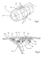
- la
figure 1 est une vue en perspective illustrant une nacelle d'aéronef, - les
figures 2 à 5 sont des coupes illustrant des variantes de l'invention, - la
figure 6A est une coupe illustrant une autre variante de l'invention dans un premier état fermé, - la
figure 6B est une coupe illustrant la variante de lafigure 6A dans un deuxième état dit ouvert, et - la
figure 6C est une coupe illustrant la variante de lafigure 6A dans un troisième état dit « mal fermé ».
- the
figure 1 is a perspective view illustrating an aircraft nacelle, - the
Figures 2 to 5 are sections illustrating variants of the invention, - the
Figure 6A is a section illustrating another variant of the invention in a first closed state, - the
Figure 6B is a section illustrating the variant of theFigure 6A in a second so-called open state, and - the
Figure 6C is a section illustrating the variant of theFigure 6A in a third state called "badly closed".
Sur la
Les capots 14 comprennent une articulation 15 par rapport au reste de la nacelle pour les rendre mobiles et autoriser l'accès à la motorisation. Ainsi, ces capots 14 permettent d'obturer ou de dégager une ouverture délimitée par un cadre.The
Ces capots 14 sont articulés au reste de la nacelle de différentes manières en fonction de la cinématique retenue et s'étendent depuis le haut de la nacelle, à proximité de l'ancrage du mât, jusqu'au bas de la nacelle et ont une forme demi-cylindrique.These
Un capot 14 comprend généralement une tôle avec des raidisseurs sur la surface intérieure pour lui conférer une rigidité relative. La surface extérieure lisse du capot est sensée rester dans le prolongement de la surface extérieure des autres éléments, notamment de l'entrée d'air, lorsque le capot est en position fermée.A
Pour la suite de la description, la direction longitudinale correspond à la direction de l'axe de rotation de la soufflante de la motorisation. Un plan médian vertical correspond à un plan vertical contenant l'axe longitudinal.For the rest of the description, the longitudinal direction corresponds to the direction of the axis of rotation of the fan of the engine. A vertical median plane corresponds to a vertical plane containing the longitudinal axis.
Une direction radiale est une direction perpendiculaire à la direction longitudinale.A radial direction is a direction perpendicular to the longitudinal direction.
Un plan tangentiel en un point donné correspond à un plan perpendiculaire à la direction radiale passant par ledit point.A tangential plane at a given point corresponds to a plane perpendicular to the radial direction passing through said point.
Les positions amont et aval sont définies en référence à la direction de l'écoulement des gaz à l'intérieur de la motorisation.The upstream and downstream positions are defined with reference to the direction of the flow of gases inside the engine.
Selon un mode de réalisation, une nacelle comprend deux capots 14 symétriques par rapport au plan médian vertical de la nacelle, chaque capot pouvant pivoter autour d'un axe de rotation 16 orienté selon la direction longitudinale et disposé à proximité du mât (approximativement à 12h).According to one embodiment, a nacelle comprises two covers 14 symmetrical with respect to the vertical median plane of the nacelle, each cover being pivotable about an axis of
Ainsi, les capots peuvent occuper plusieurs états, à savoir un état fermé (
Les bords inférieurs des capots sont sensiblement parallèles aux axes de pivotement 16 et sont reliés entre eux à l'état fermé par des moyens de verrouillage/déverrouillage 17.The lower edges of the covers are substantially parallel to the
La nacelle, le ou les capots, l'articulation du capot par rapport au reste de la nacelle, les moyens de verrouillage/déverrouillage du capot ne sont pas plus décrits car ils sont connus de l'homme du métier.The nacelle, the hood or bonnets, the hinge of the bonnet relative to the remainder of the nacelle, the means of locking / unlocking the bonnet are not described any more as they are known to those skilled in the art.
Les bords amont et aval du capot relient les bords inférieur et supérieur du capot.The upstream and downstream edges of the cover connect the lower and upper edges of the cover.
Ces bords amont et aval coopèrent avec les bords amont et aval du cadre de l'ouverture. Des moyens de positionnement et de guidage peuvent être prévus pour positionner correctement le bord amont (ou aval) du capot avec le bord amont (ou aval) de l'ouverture par exemple une gorge en V au niveau du bord de l'ouverture qui coopère avec une rainure prévue au niveau du bord du capot ou des couteaux prévus au niveau du bord du capot qui coopèrent avec des logements prévus au niveau du bord de l'ouverture.These upstream and downstream edges cooperate with the upstream and downstream edges of the frame of the opening. Positioning and guiding means may be provided to correctly position the upstream (or downstream) edge of the cover with the upstream (or downstream) edge of the opening, for example a V-shaped groove at the edge of the opening which cooperates with with a groove provided at the edge of the hood or knives provided at the edge of the hood which cooperate with housings provided at the edge of the opening.
Sur les
L'ouverture est délimitée par un cadre comprenant une paroi 24 au niveau du bord amont qui est perpendiculaire ou inclinée par rapport aux surfaces extérieures de la nacelle.The opening is delimited by a frame comprising a
Selon des variantes illustrées sur les
Selon une variante illustrée sur les
Selon les besoins, le bord amont du capot peut comprendre un ou plusieurs couteaux répartis sur la longueur du bord du capot.Depending on the requirements, the upstream edge of the hood may comprise one or more knives distributed along the length of the edge of the hood.
Selon une autre variante illustrée sur la
La nervure 32 peut s'étendre de manière continue sur toute la longueur du bord amont du capot ou se présenter sous la forme d'au moins un tronçon s'étendant sur au moins une partie de la longueur du bord amont du capot.The
Selon les variantes illustrées sur les
Dans tous les cas, pour permettre l'ouverture et la fermeture du capot, les moyens 25 de positionnement n'assurent pas le positionnement du capot par rapport au reste de la nacelle selon une direction correspondant à la direction du mouvement d'ouverture et de fermeture du capot qui correspond sensiblement à la direction radiale. Par conséquent, compte tenu de la distance entre l'axe 16 de pivotement et les moyens 17 de verrouillage/déverrouillage, le capot 14 peut se déformer selon la direction radiale et engendrer un phénomène d'écope.In any case, to allow the opening and closing of the cover, the positioning means 25 do not ensure the positioning of the cover relative to the rest of the nacelle in a direction corresponding to the direction of the opening movement and closing the cover which corresponds substantially to the radial direction. Therefore, given the distance between the
Pour ne pas altérer ses caractéristiques aérodynamiques, la nacelle comprend des moyens 37 pour limiter la déformation du capot et l'apparition du phénomène d'écope.In order not to alter its aerodynamic characteristics, the nacelle comprises means 37 for limiting the deformation of the hood and the appearance of the scoop phenomenon.
Selon l'invention, les moyens 37 pour limiter l'apparition du phénomène d'écope comprennent au moins un couple électromagnétique dont un élément 38 est solidaire du reste de la nacelle et dont l'autre élément 40 est solidaire du capot, au moins l'un des deux éléments émettant un champs magnétique générant un effort d'attraction sur l'autre élément.According to the invention, the
Selon un mode de réalisation, le premier élément 38 est un aimant permanent. En variante, le premier élément 38 est un électroaimant qui génère un champs magnétique lorsqu'il est alimenté en électricité. Dans ce cas, les moyens 37 pour limiter l'apparition du phénomène d'écope peuvent être activés ou désactivés. Cette solution est privilégiée car elle permet de ne pas activer les moyens 37 pour limiter l'apparition du phénomène d'écope notamment lorsqu'on souhaite manoeuvrer le capot et de ne les activer que lorsque le capot est à l'état fermé. Avantageusement, l'électroaimant 38 est solidarisé à la partie fixe à savoir le reste de la nacelle.According to one embodiment, the
En complément, le second élément 40 est en matériau magnétique.In addition, the
Chaque capot 14 comprend au moins un couple électromagnétique. Selon les cas, le capot peut comprendre plusieurs couples électromagnétiques répartis sur la longueur du bord amont du capot. Avantageusement, le ou les couples sont disposés dans les zones susceptibles de voir apparaître les phénomènes d'écope à savoir à proximité des zones correspondant à 3 h ou 9 h ( à mi distance entre l'axe de pivotement et le bord inférieur du capot).Each
Afin d'optimiser le fonctionnement du couple électromagnétique, il est nécessaire que les deux éléments 38 et 40 soient correctement positionnés l'un par rapport à l'autre.In order to optimize the operation of the electromagnetic torque, it is necessary for the two
Selon une première variante, un couple électromagnétique 38, 40 est positionné à proximité des moyens de positionnement.According to a first variant, an
Selon une première variante illustrée sur la
Selon une autre variante illustrée sur la
Selon une autre variante illustrée sur la
Afin de positionner correctement les deux éléments du couple électromagnétique l'un par rapport à l'autre, la liaison entre au moins l'un des deux éléments 38, 40 et son support (capot ou reste de la nacelle) autorise un léger débattement qui permet de corriger un léger désalignement.In order to correctly position the two elements of the electromagnetic torque relative to each other, the connection between at least one of the two
Comme illustré sur les
Selon les cas, un couple électromagnétique est disposé à proximité des moyens 25 de positionnement et au moins l'un des deux éléments dudit couple électromagnétique est mobile par rapport à son support.Depending on the case, an electromagnetic torque is disposed near the positioning means 25 and at least one of the two elements of said electromagnetic torque is movable relative to its support.
En variante, au moins l'un des deux éléments d'un couple électromagnétique est mobile par rapport à son support et ledit couple électromagnétique est distant des moyens 25 de positionnement ou un couple électromagnétique est disposé à proximité des moyens 25 de positionnement et les deux éléments dudit couple sont fixes par rapport aux supports.As a variant, at least one of the two elements of an electromagnetic torque is mobile with respect to its support and the electromagnetic torque is distant. positioning means 25 or electromagnetic torque is disposed near the positioning means 25 and the two elements of said pair are fixed relative to the supports.
Selon un autre aspect de l'invention, les faces des deux éléments du couple électromagnétique plaquées l'une contre l'autre sont disposées dans des plans ayant au moins une composante selon la direction radiale.According to another aspect of the invention, the faces of the two elements of the electromagnetic couple pressed against each other are arranged in planes having at least one component in the radial direction.
Cet agencement permet de compenser un éventuel mauvais positionnement des deux éléments selon la direction radiale.This arrangement makes it possible to compensate for a possible bad positioning of the two elements in the radial direction.
Dans le cas contraire, si les faces des deux éléments sont disposées dans des plans tangentiels et si l'entrefer (distance séparant lesdites faces) est trop important, la force d'attraction entre les deux éléments 38 et 40 peut ne pas être suffisante pour maintenir le capot en position par rapport au reste de la nacelle.In the opposite case, if the faces of the two elements are arranged in tangential planes and if the gap (distance separating said faces) is too great, the attraction force between the two
Selon des modes de réalisation illustrés sur les
Ainsi, comme illustré sur la
Selon un autre mode de réalisation, comme illustré sur la
De préférence, les faces des deux éléments 38 et 40 font un angle inférieur à 60° par rapport à la direction radiale.Preferably, the faces of the two
Claims (7)
Applications Claiming Priority (1)
| Application Number | Priority Date | Filing Date | Title |
|---|---|---|---|
| FR1058783A FR2966432B1 (en) | 2010-10-26 | 2010-10-26 | AIRCRAFT COVER INCORPORATING MEANS FOR LIMITING MAGNETIC TYPE ECOPE PHENOMENA |
Publications (2)
| Publication Number | Publication Date |
|---|---|
| EP2447158A2 true EP2447158A2 (en) | 2012-05-02 |
| EP2447158A3 EP2447158A3 (en) | 2013-11-06 |
Family
ID=44064198
Family Applications (1)
| Application Number | Title | Priority Date | Filing Date |
|---|---|---|---|
| EP20110306374 Withdrawn EP2447158A3 (en) | 2010-10-26 | 2011-10-25 | Aircraft cowl including a means for limiting magnetic scoop phenomena |
Country Status (3)
| Country | Link |
|---|---|
| US (1) | US20120097260A1 (en) |
| EP (1) | EP2447158A3 (en) |
| FR (1) | FR2966432B1 (en) |
Families Citing this family (4)
| Publication number | Priority date | Publication date | Assignee | Title |
|---|---|---|---|---|
| US9708073B2 (en) * | 2014-08-22 | 2017-07-18 | Rohr, Inc. | Automatic deflection limiting latches for a thrust reverser |
| US10072511B2 (en) * | 2014-10-02 | 2018-09-11 | Rolls-Royce North American Technologies Inc. | Engine nacelle |
| FR3085353A1 (en) * | 2018-09-04 | 2020-03-06 | Airbus Operations | AIRCRAFT TURBOMACHINE ASSEMBLY WITH ARTICULATED HOOD |
| US11414200B2 (en) * | 2019-04-29 | 2022-08-16 | Rohr, Inc. | Fan cowl securement retainers |
Citations (1)
| Publication number | Priority date | Publication date | Assignee | Title |
|---|---|---|---|---|
| FR2933957A1 (en) | 2008-07-18 | 2010-01-22 | Airbus France | DEVICE FOR BELTING AN AIRCRAFT NACELLE |
Family Cites Families (3)
| Publication number | Priority date | Publication date | Assignee | Title |
|---|---|---|---|---|
| FR2887225B1 (en) * | 2005-06-21 | 2008-09-19 | Airbus France Sas | AIRCRAFT NACELLE, AND AIRCRAFT EQUIPPED WITH AT LEAST ONE SUCH NACELLE |
| FR2939410B1 (en) * | 2008-12-04 | 2012-06-15 | Airbus France | SYSTEM FOR CLOSING A FLOWER HOOD FOR AN AIRCRAFT |
| FR2960854B1 (en) * | 2010-06-04 | 2012-07-20 | Airbus Operations Sas | DOUBLE FUNCTION DOOR FOR AIRCRAFT ENGINE NACELLE |
-
2010
- 2010-10-26 FR FR1058783A patent/FR2966432B1/en not_active Expired - Fee Related
-
2011
- 2011-10-19 US US13/276,489 patent/US20120097260A1/en not_active Abandoned
- 2011-10-25 EP EP20110306374 patent/EP2447158A3/en not_active Withdrawn
Patent Citations (1)
| Publication number | Priority date | Publication date | Assignee | Title |
|---|---|---|---|---|
| FR2933957A1 (en) | 2008-07-18 | 2010-01-22 | Airbus France | DEVICE FOR BELTING AN AIRCRAFT NACELLE |
Also Published As
| Publication number | Publication date |
|---|---|
| US20120097260A1 (en) | 2012-04-26 |
| FR2966432B1 (en) | 2013-08-30 |
| FR2966432A1 (en) | 2012-04-27 |
| EP2447158A3 (en) | 2013-11-06 |
Similar Documents
| Publication | Publication Date | Title |
|---|---|---|
| EP2222560B1 (en) | Aircraft nacelle guidance system installation | |
| EP2310269B1 (en) | Device for shrouding an aircraft nacelle | |
| EP2898211B1 (en) | Thrust reverser device fixed structure | |
| CA2204589C (en) | Jet turbine engine thrust reverser employing doors fitted with deflector vanes | |
| EP2313317B1 (en) | Device for shrouding an aircraft nacelle | |
| CA2239462C (en) | Bypass turbojet thrust reverser with doors fitted with a movable spoiler with optimized drive | |
| EP1896717A1 (en) | Aircraft pod and aircraft equipped with at least one such pod | |
| EP0777045A1 (en) | Thrust reverser with doors with linked rear panel | |
| FR2966433A1 (en) | AIRCRAFT HOOD INCORPORATING MEANS FOR LIMITING PNEUMATIC ECOPE PHENOMENA | |
| FR2955312A1 (en) | DEVICE FOR FUSIBLE CONNECTION BETWEEN A MOBILE PART AND A FIXED PART OF AN AIRCRAFT NACELLE | |
| EP0828934A1 (en) | Double door thrust reverser assembly | |
| EP2447158A2 (en) | Aircraft cowl including a means for limiting magnetic scoop phenomena | |
| EP0764779A1 (en) | Thrust reverser with doors linked to a primary panel | |
| FR2953490A1 (en) | REPLACEMENT OF NACELLE FOR TURBOJET ENGINE | |
| EP1535840A1 (en) | Device for mounting a fairing between a nacelle of an aircraft engine and a pylon | |
| EP2761158A1 (en) | Thrust reverser gates having side openings | |
| EP0877155A1 (en) | Supplementary air inlet openings for gas turbine in supersonic aeroplane | |
| WO1998040618A1 (en) | Bypass turbojet thrust reverser having doors with streamlined external structure | |
| EP3717766B1 (en) | Thrust reverser for an aircraft engine nacelle, comprising a panel for avoiding a movable slat of the wing, and nacelle associated therewith | |
| EP3572331A1 (en) | Aircraft comprising at least one cover provided with an improved connection system | |
| FR3053402A1 (en) | ARRANGEMENT FOR THE FASTENING OF A THRUST INVERSION TRAP ROD ON A FIXED INTERNAL STRUCTURE OF A TURBOJET NACELLE AND ASSOCIATED MOUNTING / DISMANTLING METHOD | |
| FR2949435A1 (en) | Nacelle for turbojet engine of airplane, has centering and positioning unit centering and positioning movable structure on fixed structure, where unit is formed from male and female annular sectors mounted on movable or fixed structure | |
| FR2769953A1 (en) | Turbofan engine thrust reverser | |
| FR2627806A1 (en) | Jet engine reverse thrust deflector - comprises hinged panel with additional flaps on inner edges for improved gas flow direction | |
| FR2953491A1 (en) | AIRCRAFT NACELLE INCORPORATING A DEVICE FOR PROTECTING A ACCESS COMPONENT FOR A LATCHING SYSTEM |
Legal Events
| Date | Code | Title | Description |
|---|---|---|---|
| PUAI | Public reference made under article 153(3) epc to a published international application that has entered the european phase |
Free format text: ORIGINAL CODE: 0009012 |
|
| AK | Designated contracting states |
Kind code of ref document: A2 Designated state(s): AL AT BE BG CH CY CZ DE DK EE ES FI FR GB GR HR HU IE IS IT LI LT LU LV MC MK MT NL NO PL PT RO RS SE SI SK SM TR |
|
| AX | Request for extension of the european patent |
Extension state: BA ME |
|
| PUAL | Search report despatched |
Free format text: ORIGINAL CODE: 0009013 |
|
| AK | Designated contracting states |
Kind code of ref document: A3 Designated state(s): AL AT BE BG CH CY CZ DE DK EE ES FI FR GB GR HR HU IE IS IT LI LT LU LV MC MK MT NL NO PL PT RO RS SE SI SK SM TR |
|
| AX | Request for extension of the european patent |
Extension state: BA ME |
|
| RIC1 | Information provided on ipc code assigned before grant |
Ipc: B64D 29/08 20060101ALI20131001BHEP Ipc: B64D 29/06 20060101AFI20131001BHEP |
|
| STAA | Information on the status of an ep patent application or granted ep patent |
Free format text: STATUS: THE APPLICATION IS DEEMED TO BE WITHDRAWN |
|
| 18D | Application deemed to be withdrawn |
Effective date: 20140507 |