EP2447125A2 - Idling stop control device - Google Patents
Idling stop control device Download PDFInfo
- Publication number
- EP2447125A2 EP2447125A2 EP11186838A EP11186838A EP2447125A2 EP 2447125 A2 EP2447125 A2 EP 2447125A2 EP 11186838 A EP11186838 A EP 11186838A EP 11186838 A EP11186838 A EP 11186838A EP 2447125 A2 EP2447125 A2 EP 2447125A2
- Authority
- EP
- European Patent Office
- Prior art keywords
- engine
- predetermined
- clutch
- braking force
- time
- Prior art date
- Legal status (The legal status is an assumption and is not a legal conclusion. Google has not performed a legal analysis and makes no representation as to the accuracy of the status listed.)
- Granted
Links
Images


Classifications
-
- B—PERFORMING OPERATIONS; TRANSPORTING
- B60—VEHICLES IN GENERAL
- B60W—CONJOINT CONTROL OF VEHICLE SUB-UNITS OF DIFFERENT TYPE OR DIFFERENT FUNCTION; CONTROL SYSTEMS SPECIALLY ADAPTED FOR HYBRID VEHICLES; ROAD VEHICLE DRIVE CONTROL SYSTEMS FOR PURPOSES NOT RELATED TO THE CONTROL OF A PARTICULAR SUB-UNIT
- B60W30/00—Purposes of road vehicle drive control systems not related to the control of a particular sub-unit, e.g. of systems using conjoint control of vehicle sub-units
- B60W30/18—Propelling the vehicle
- B60W30/18009—Propelling the vehicle related to particular drive situations
- B60W30/18018—Start-stop drive, e.g. in a traffic jam
-
- B—PERFORMING OPERATIONS; TRANSPORTING
- B60—VEHICLES IN GENERAL
- B60W—CONJOINT CONTROL OF VEHICLE SUB-UNITS OF DIFFERENT TYPE OR DIFFERENT FUNCTION; CONTROL SYSTEMS SPECIALLY ADAPTED FOR HYBRID VEHICLES; ROAD VEHICLE DRIVE CONTROL SYSTEMS FOR PURPOSES NOT RELATED TO THE CONTROL OF A PARTICULAR SUB-UNIT
- B60W10/00—Conjoint control of vehicle sub-units of different type or different function
- B60W10/04—Conjoint control of vehicle sub-units of different type or different function including control of propulsion units
- B60W10/06—Conjoint control of vehicle sub-units of different type or different function including control of propulsion units including control of combustion engines
-
- B—PERFORMING OPERATIONS; TRANSPORTING
- B60—VEHICLES IN GENERAL
- B60W—CONJOINT CONTROL OF VEHICLE SUB-UNITS OF DIFFERENT TYPE OR DIFFERENT FUNCTION; CONTROL SYSTEMS SPECIALLY ADAPTED FOR HYBRID VEHICLES; ROAD VEHICLE DRIVE CONTROL SYSTEMS FOR PURPOSES NOT RELATED TO THE CONTROL OF A PARTICULAR SUB-UNIT
- B60W10/00—Conjoint control of vehicle sub-units of different type or different function
- B60W10/18—Conjoint control of vehicle sub-units of different type or different function including control of braking systems
- B60W10/184—Conjoint control of vehicle sub-units of different type or different function including control of braking systems with wheel brakes
-
- F—MECHANICAL ENGINEERING; LIGHTING; HEATING; WEAPONS; BLASTING
- F02—COMBUSTION ENGINES; HOT-GAS OR COMBUSTION-PRODUCT ENGINE PLANTS
- F02N—STARTING OF COMBUSTION ENGINES; STARTING AIDS FOR SUCH ENGINES, NOT OTHERWISE PROVIDED FOR
- F02N11/00—Starting of engines by means of electric motors
- F02N11/10—Safety devices
- F02N11/106—Safety devices for stopping or interrupting starter actuation
-
- B—PERFORMING OPERATIONS; TRANSPORTING
- B60—VEHICLES IN GENERAL
- B60W—CONJOINT CONTROL OF VEHICLE SUB-UNITS OF DIFFERENT TYPE OR DIFFERENT FUNCTION; CONTROL SYSTEMS SPECIALLY ADAPTED FOR HYBRID VEHICLES; ROAD VEHICLE DRIVE CONTROL SYSTEMS FOR PURPOSES NOT RELATED TO THE CONTROL OF A PARTICULAR SUB-UNIT
- B60W2510/00—Input parameters relating to a particular sub-units
- B60W2510/02—Clutches
- B60W2510/0208—Clutch engagement state, e.g. engaged or disengaged
-
- B—PERFORMING OPERATIONS; TRANSPORTING
- B60—VEHICLES IN GENERAL
- B60W—CONJOINT CONTROL OF VEHICLE SUB-UNITS OF DIFFERENT TYPE OR DIFFERENT FUNCTION; CONTROL SYSTEMS SPECIALLY ADAPTED FOR HYBRID VEHICLES; ROAD VEHICLE DRIVE CONTROL SYSTEMS FOR PURPOSES NOT RELATED TO THE CONTROL OF A PARTICULAR SUB-UNIT
- B60W2510/00—Input parameters relating to a particular sub-units
- B60W2510/06—Combustion engines, Gas turbines
- B60W2510/0638—Engine speed
- B60W2510/0642—Idle condition
-
- B—PERFORMING OPERATIONS; TRANSPORTING
- B60—VEHICLES IN GENERAL
- B60W—CONJOINT CONTROL OF VEHICLE SUB-UNITS OF DIFFERENT TYPE OR DIFFERENT FUNCTION; CONTROL SYSTEMS SPECIALLY ADAPTED FOR HYBRID VEHICLES; ROAD VEHICLE DRIVE CONTROL SYSTEMS FOR PURPOSES NOT RELATED TO THE CONTROL OF A PARTICULAR SUB-UNIT
- B60W2520/00—Input parameters relating to overall vehicle dynamics
- B60W2520/04—Vehicle stop
-
- B—PERFORMING OPERATIONS; TRANSPORTING
- B60—VEHICLES IN GENERAL
- B60W—CONJOINT CONTROL OF VEHICLE SUB-UNITS OF DIFFERENT TYPE OR DIFFERENT FUNCTION; CONTROL SYSTEMS SPECIALLY ADAPTED FOR HYBRID VEHICLES; ROAD VEHICLE DRIVE CONTROL SYSTEMS FOR PURPOSES NOT RELATED TO THE CONTROL OF A PARTICULAR SUB-UNIT
- B60W2520/00—Input parameters relating to overall vehicle dynamics
- B60W2520/10—Longitudinal speed
-
- B—PERFORMING OPERATIONS; TRANSPORTING
- B60—VEHICLES IN GENERAL
- B60W—CONJOINT CONTROL OF VEHICLE SUB-UNITS OF DIFFERENT TYPE OR DIFFERENT FUNCTION; CONTROL SYSTEMS SPECIALLY ADAPTED FOR HYBRID VEHICLES; ROAD VEHICLE DRIVE CONTROL SYSTEMS FOR PURPOSES NOT RELATED TO THE CONTROL OF A PARTICULAR SUB-UNIT
- B60W2540/00—Input parameters relating to occupants
- B60W2540/12—Brake pedal position
-
- B—PERFORMING OPERATIONS; TRANSPORTING
- B60—VEHICLES IN GENERAL
- B60W—CONJOINT CONTROL OF VEHICLE SUB-UNITS OF DIFFERENT TYPE OR DIFFERENT FUNCTION; CONTROL SYSTEMS SPECIALLY ADAPTED FOR HYBRID VEHICLES; ROAD VEHICLE DRIVE CONTROL SYSTEMS FOR PURPOSES NOT RELATED TO THE CONTROL OF A PARTICULAR SUB-UNIT
- B60W2540/00—Input parameters relating to occupants
- B60W2540/14—Clutch pedal position
-
- B—PERFORMING OPERATIONS; TRANSPORTING
- B60—VEHICLES IN GENERAL
- B60W—CONJOINT CONTROL OF VEHICLE SUB-UNITS OF DIFFERENT TYPE OR DIFFERENT FUNCTION; CONTROL SYSTEMS SPECIALLY ADAPTED FOR HYBRID VEHICLES; ROAD VEHICLE DRIVE CONTROL SYSTEMS FOR PURPOSES NOT RELATED TO THE CONTROL OF A PARTICULAR SUB-UNIT
- B60W2710/00—Output or target parameters relating to a particular sub-units
- B60W2710/18—Braking system
- B60W2710/182—Brake pressure, e.g. of fluid or between pad and disc
-
- B—PERFORMING OPERATIONS; TRANSPORTING
- B60—VEHICLES IN GENERAL
- B60W—CONJOINT CONTROL OF VEHICLE SUB-UNITS OF DIFFERENT TYPE OR DIFFERENT FUNCTION; CONTROL SYSTEMS SPECIALLY ADAPTED FOR HYBRID VEHICLES; ROAD VEHICLE DRIVE CONTROL SYSTEMS FOR PURPOSES NOT RELATED TO THE CONTROL OF A PARTICULAR SUB-UNIT
- B60W30/00—Purposes of road vehicle drive control systems not related to the control of a particular sub-unit, e.g. of systems using conjoint control of vehicle sub-units
- B60W30/18—Propelling the vehicle
- B60W30/18009—Propelling the vehicle related to particular drive situations
- B60W30/18109—Braking
- B60W30/18118—Hill holding
-
- F—MECHANICAL ENGINEERING; LIGHTING; HEATING; WEAPONS; BLASTING
- F02—COMBUSTION ENGINES; HOT-GAS OR COMBUSTION-PRODUCT ENGINE PLANTS
- F02N—STARTING OF COMBUSTION ENGINES; STARTING AIDS FOR SUCH ENGINES, NOT OTHERWISE PROVIDED FOR
- F02N11/00—Starting of engines by means of electric motors
- F02N11/08—Circuits specially adapted for starting of engines
- F02N11/0814—Circuits specially adapted for starting of engines comprising means for controlling automatic idle-start-stop
- F02N11/0818—Conditions for starting or stopping the engine or for deactivating the idle-start-stop mode
Definitions
- This disclosure generally relates to an idling stop control device.
- the idling stop device automatically stops an idling of an engine when a moving vehicle comes to a temporary stop at a red signal or similar situations and automatically starts the engine when the vehicle starts moving again.
- the idling stop device improves fuel efficiency according to a length of time the idling is stopped. By cutting off the emission gas during an idling period, the idling stop device effectively reduces an environmental impact by reducing CO 2 .
- the idling stop device also effectively cuts off an engine noise during the idling period for pedestrians and neighborhood consideration.
- detecting driver's intentions with accuracy is important for controlling the engine according to the driver's intentions.
- An example of a control device for such an idling stop device is disclosed in JP2002-188480A .
- the control device disclosed in JP2002-188480A for automatically stopping and starting an engine controls the engine according to a predetermined automatic engine stop condition and a predetermined automatic engine start condition.
- the control device automatically stops the engine when a vehicle speed is less than or equal to a set value excluding zero, and in addition, an idle switch is ON, and further, the gear position of the transmission is in neutral.
- the control device automatically starts the engine when an engaged clutch state is changed to a release state, or the gear position of the transmission is at a position other than neutral, or the idle switch is OFF, or a state of a booster is in a predetermined negative pressure.
- the control device describes that the aforementioned conditions provides controls for the automatic stop and the automatic start of the engine that comfortably match the driver's intentions.
- the control device disclosed in JP2002-188480A includes the position of the transmission is in neutral as one of the conditions for the automatic stop of the engine. According to the control device, the position of the transmission is in neutral because if the transmission is in a drive position and the clutch is engaged, the engine and driving wheels and related members therebetween are interlocked and the inertia of rotating members becomes too large for a starter to start the engine automatically. Therefore, the idling stop function does not work when the driver stops the vehicle temporarily by pressing the clutch pedal and the brake pedal with the transmission in the drive position.
- the control device disclosed in JP2002-188480A also includes changing an engaged clutch state to a release state and the gear position of the transmission in a position other than neutral as conditions for the automatic start of the engine. Due to these conditions, the engine automatically starts when the clutch pedal is pressed or the gear is shifted to a drive position, however, a certain time is necessary before the vehicle starts moving after the brake pedal is released. With the control device disclosed in JP2002-188480A , fuel is consumed unnecessarily during this certain time.
- assuring the idling stop function with higher vehicle safety is highly important for preventing risks at the time of the automatic start of the engine, for example, an unintentional sudden start (or a sudden acceleration), an unintentional engine stop (or an engine stall), or a backward vehicle motion (or a rear motion) that occurs when moving the vehicle from the temporary stop on a slope.
- an idling stop control device adapted to connect a transmission to an engine mounted to a vehicle to be selectively engaged via a clutch, automatically stops an engine upon satisfaction of a predetermined stop condition during an idling of the engine and automatically starts the engine upon satisfaction of a predetermined start condition when the engine is in an automatic stop state.
- a braking force sustaining means generates a predetermined braking force irrespective of an operation amount of a brake operation member and a start judgment means judges satisfaction of the predetermined start condition.
- an automatic start means automatically starts the engine.
- a braking force release means releases a predetermined braking force when a predetermined hold time duration elapses from a specific point in time where the operation amount of the brake operation member starts decreasing or comes to zero.
- the predetermined start condition requires the clutch in a disengaged state and, additionally, the operation amount of the brake operation member to decrease or to become zero.
- the decrease or a complete loss of the operation amount of the brake operation member is included as a requirement for the predetermined start condition, so that the automatic start of the engine effectively reflects a driver's intention to move.
- the engine is automatically stopped as long as possible and automatically started just before the vehicle starts moving, thus improves fuel efficiency.
- the predetermined start condition also includes the clutch in a disengaged state as a requirement, which means the engine is automatically started in a state that the transmission, driving wheels and rotating members that lie between them are disconnected. As a result, the engine start by a starter becomes more reliable and an engine stall is avoided.
- the predetermined braking force is generated irrespective of the operation amount of the brake operation member and is sustained over the predetermined hold time duration. As a result, a sudden acceleration of the vehicle unintentional to the driver is avoided.
- the idling stop control device further includes a start restricting means such that restricts the start of the engine despite the predetermined start condition is satisfied, when the clutch is operated to contact from a disengaged state before a predetermined allowed time duration elapses, which is a duration shorter than the predetermined hold time duration, from the specific point in time where the operation amount of the brake operation member starts decreasing or comes to zero.
- the idling stop control device restricts the start of the engine when the clutch is operated to contact from a disengaged state before the predetermined allowed time duration elapses from the specific point in time where the decrease or the complete loss of the operation amount occurs in the brake operation member, despite the predetermined start condition is satisfied.
- the start of the engine is restricted. Because the start of the engine is restricted when the clutch is engaged, risks for example a sudden acceleration or an engine stall are avoided.
- the idling stop control device further includes a movement allowing means releasing the predetermined braking force immediately when the allowed time duration elapses from the specific point in time where the operation amount of the brake operation member starts decreasing or comes to zero and when the clutch is operated to contact from a disengaged state before the predetermined hold time duration elapses.
- the idling stop control device releases the predetermined braking force immediately when the allowed time duration elapses from the specific point in time where the decrease or the complete loss of the operation amount occurs in the brake operation member and when the clutch is operated to contact from the disengaged state before the hold time duration elapses.
- Fuel efficiency is improved because after the automatic start of the engine, the vehicle is allowed to start moving at an intended timing of the driver. Furthermore, because the braking force is sustained until the clutch comes to the contact state just before the vehicle starts moving, the rear motion that occurs when moving the vehicle from the temporary stop on a slope is prevented.
- the idling stop control device further includes a stop judgment means judging a satisfaction of the predetermined stop condition while the vehicle is in motion, an automatic stop means stopping the engine automatically when the predetermined stop condition is satisfied, an engine-stopped-period braking force generation means generating the predetermined braking force when the vehicle speed comes to zero after the automatic stop of the engine, and the predetermined stop condition requiring a speed of the vehicle as less than or equal to a predetermined vehicle speed or a speed of the engine as less than or equal to a predetermined engine speed.
- the predetermined stop condition requires the speed of the vehicle or the speed of the engine as less than or equal to the predetermined speed for each, the engine is automatically stopped before the vehicle comes to a complete stop, which leads to an improved fuel efficiency. Furthermore, when the vehicle speed reaches zero, a predetermined braking force is generated irrespective of the operation amount of the brake operation member. As a result, the rear motion that occurs when moving the vehicle from the temporary stop on a slope is effectively prevented, as well as a sudden acceleration is avoided whenever the engine automatically starts.
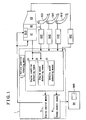
- Fig. 1 is a block diagram illustrating a functional configuration including a powertrain configuration of an embodiment of an idling stop control device equipped on a vehicle.
- Fig. 2 is a flow diagram showing a control procedure for an automatic engine stop by the idling stop control device.
- Fig. 3 is a flow diagram showing a control procedure for an automatic engine start by the idling stop control device.
- Fig. 4 is a time-line diagram illustrating an example of the automatic engine stop by the idling stop control device.
- Fig. 5 is a time-line diagram illustrating an example of the automatic engine start by the idling stop control device during a typical operation.
- Fig. 6 is a time-line diagram illustrating an example of the automatic engine start by the idling stop control device when the clutch contact operation is delayed.
- Fig. 7 is a time-line diagram illustrating an example of the automatic engine start by the idling stop control device when the clutch operation is too early and a stating of the engine is restricted.
- Fig. 1 is a block diagram illustrating a functional configuration including a powertrain configuration of an embodiment of the idling stop control device 1 equipped on a vehicle. Arrows in Fig. 1 represent flow directions of controls, for example, measured values or commands.
- the powertrain of the vehicle includes an engine 91, a clutch 92, a transmission 93.
- the engine 91 includes a starter 915 that uses a starter motor.
- the clutch 92 connects the engine 91 and the transmission 93 in a selectively engaging manner.
- An output shaft of the transmission 93 is connected to driving wheels via axles.
- An accelerator pedal 911 is provided for controlling an air-fuel mixture supply amount to the engine 91.
- the accelerator pedal 911 is provided with an accelerator opening degree sensor 912 for detecting an amount of the accelerator pedal 911 pressed for the operations.
- a clutch pedal 921 is provided for controlling the clutch 92.
- the clutch pedal 921 is provided with a clutch pedal stroke sensor 922 for detecting an amount of the clutch pedal 921 pressed for the operations.
- the clutch 92 is of a conventional type, which is disengaged when a driver presses the clutch pedal 921, becomes a contact state and starts to be engaged when the pressed amount of the clutch pedal 21 is reduced, and is fully engaged when the pressed amount of the clutch pedal 21 is reduced to zero.
- the transmission 93 is a manual transmission in which the driver controls a shift lever to change gear positions of the transmission, for example, in D for driving in a forward direction, in R for reversing the direction, or in N for a neutral state.
- the transmission 93 includes a shift position sensor 932, which detects a shift position SP of the shift lever.
- the vehicle is equipped with a brake system 94, which applies a braking force to each wheel.
- a conventional type brake system which uses a braking pressure of a hydraulic fluid for applying the braking force to each wheel, may be used as the brake system 94.
- a brake pedal 941 is provided as a brake operation member for actuating the brake system 94, and a braking switch 942 is provided for detecting an amount of the brake pedal 941 pressed for an operation.
- the brake system 94 is equipped with a built-in braking pressure generating means 945 that operates independently from the operation of the brake pedal 941.
- the braking pressure generating means 945 generates a predetermined braking force irrespective of the amount of the brake pedal 941 pressed for the operation.
- An electric oil pump or an accumulator tank, for example, may be used as the braking pressure generating means 945.
- the idling stop control device 1 includes a vehicle condition detecting means 2, an engine control means 3, and a brake control means 4.
- the vehicle condition detecting means 2, the engine control means 3, and the brake control means 4 may be configured by combining an electronic control unit (ECU) and a sensor appropriately.
- ECU electronice control unit
- the vehicle condition detecting means 2 includes an engine condition detecting means 21 and an engine speed detecting means 22 for detecting an operation status and a speed of the engine 91.
- the vehicle condition detecting means 2 also includes a vehicle speed detecting means 23 for detecting a traveling speed of a vehicle (or a vehicle speed).
- the vehicle condition detecting means 2 receives a signal on an amount of the accelerator pedal 911 being pressed for operation sent from the signal accelerator opening degree sensor 912.
- the vehicle condition detecting means 2 receives a signal on an amount of the clutch pedal 921 being pressed for operation from the clutch pedal stroke sensor 922, a signal on a shift position SP of the shift lever of the transmission 93 from the shift position sensor 932, and a signal on an amount of the brake pedal 941 being pressed for operation from the braking switch 942.
- the engine control means 3 receives information on the operation status and the speed of the engine 91, the traveling speed of the vehicle, the amount of each pedal 911, 921, 941 pressed for operation, and the shift position SP of the shift lever of the transmission 93 from the vehicle condition detecting means 2. According to the information received, the engine control means 3 judges whether the predetermined stop condition, which automatically stops the engine 91, and the predetermined start condition, which automatically starts the engine 91, are satisfied or not. Further, according to the judgment results, the engine control means 3 sends necessary control signals, which automatically stop and automatically start the engine 91, to the engine 91 and the starter 915. According to the received control signals, the engine 91 and the starter 915 process an automatic start and an automatic stop of the engine 91.
- the brake control means 4 receives each of the aforementioned information from the vehicle condition detecting means 2.
- the brake control means 4 calculates amount of a necessary braking force according to the received information and sends a control signal to the brake system 94.
- the brake system 94 generates and applies the necessary braking force to each wheel according to the received control signal.
- the brake control means 4 may control the braking force as a whole, or the braking force applied to each wheel may be controlled by a combination of the brake control means 4 and a direct actuation of the brake system 94 by the brake pedal 941, which generates the braking force in part.
- Fig. 2 is a flow diagram showing a control procedure for an automatic stop of the engine 91 by the idling stop control device 1.
- Fig. 3 is a flow diagram showing a control procedure for an automatic start of the engine 91 by the idling stop control device 1.
- Step S1 in Fig. 2 for the automatic stop procedure postulates that the engine 91 is in motion.
- the idling stop control device 1 judges whether the traveling speed of the vehicle, or a vehicle speed V, is less than or equal to a predetermined speed V0 or not in Step S2.
- the predetermined speed V0 is determined to be equal to the vehicle speed when the engine 91 maintains an idling state engine speed.
- Step S5 whether the clutch pedal 921 is pressed or not, or in other words whether the clutch 92 is engaged or disengaged, is judged.
- Step S6 a shift position SP of the shift lever of the transmission 93 is identified.
- Step S8 the shift position SP of the shift lever of the transmission 93 is identified.
- Step S8 the shift position SP of the shift lever of the transmission 93 is identified.
- Step S2 the traveling speed of the vehicle (vehicle speed V) to be less than or equal to the predetermined speed V0 is defined as a requirement for the automatic stop of the engine 91.
- Step S6 when the clutch 92 is disengaged and the shift position SP of the shift lever is in reverse R (the gear position R for driving backward), the vehicle is assumed to be in a back-in parking state, therefore, to avoid an operational confusion, the procedure does not proceed to the automatic stop of the engine 91.
- Step S7 when the clutch 92 is engaged and the shift position SP of the shift lever is in a position other than neutral N, assuming the driver has an intention to accelerate again or to move the vehicle in some other way, the procedure does not proceed to the automatic stop of the engine 91.
- Step S9 After the automatic stop of the engine 91 in Step S8, the procedure proceeds to Step S9, which waits for the vehicle speed V to be reduced to zero.
- a predetermined braking force is generated by a cooperative brake control in Step S10.
- the braking pressure generating means 945 is actuated and controlled to generate a predetermined braking force irrespective of the amount of the brake pedal 941 pressed for operation.
- Steps S9 and S10 serve as engine-stopped-period braking force generation means.
- the automatic start of the engine 91 begins with a confirmation of the vehicle speed V in Step S21 in Fig. 3 for describing the flow of an automatic start procedure.
- the procedure proceeds to Step S22 and starts the engine 91 while generating speed by a conventional method.
- a situation example for proceeding from Step S21 to Step S22 is when a signal Is changed to green while the vehicle is coming to a temporary stop at a red signal and the driver decides to accelerate the vehicle again.
- Step S9 in Fig. 2 is in the situation similar to that of Step S21.
- the procedure proceeds to Step S23 to judge whether the accelerator pedal 911 is released or not.
- Step S24 when the shift position SP of the shift lever of the transmission 93 is in a position other than neutral N, assuming the driver has the intention to move the vehicle, the procedure proceeds to Step S25.
- Step S25 when the shift position SP in Step S24 is in neutral N, the procedure goes back to Step S21.
- Step S25 when the shift position SP of the shift lever is in reverse R, the procedure proceeds to Step S26 and immediately starts the engine 91, as shifting to reverse R indicates an intention to move the vehicle.
- Step S25 when the shift position SP of the shift lever is in D for driving in a forward direction, the procedure proceeds to Step S27, the step which judges whether the clutch pedal 921 is pressed or not, or in other words whether the clutch 92 is engaged or disengaged.
- Step S28 when the clutch is disengaged, the procedure proceeds to Step S28 and the procedure goes back to Step S21 when the clutch is engaged.
- Step S28 whether an operation amount of the brake pedal 941 is decreasing or not is judged.
- Step S29 when the condition is not satisfied, the procedure goes back to Step S21.
- Step S29 whether or not a predetermined braking pressure is sustained at the wheels is determined.
- the braking pressure generating means 945 When more braking pressure is necessary, the braking pressure generating means 945 is actuated and is controlled to generate the braking pressure necessary to sustain the predetermined braking pressure. Normally, the predetermined braking pressure is generated and sustained in Step S10 of the procedure for the automatic stop of the engine 91, described in Fig. 2 . In next Step S30, the starter 915 initiates the automatic start of the engine 91.
- Step S27 and S28 When conditions in Steps S27 and S28 are not satisfied, the procedure goes back to the Step S21.
- the clutch 92 being disengaged and the decrease of the operation amount of the brake pedal 41 are defined as requirements for the automatic start of the engine 91.
- Steps S21 to S28 serve as start judgment means
- Step S10 in Fig. 2 and Step S29 serve as braking force sustaining means
- Step S30 serves as a automatic start means.
- Step S31 judges whether or not a release operation of the clutch pedal 921 has started within an allowed time B duration, that is, in other words, whether or not the clutch 92 has operated to contact from the disengaged state.
- the allowed time B duration is initiated when the decrease of the operation amount of the brake pedal 941 has started. Considering that starting of the engine 91 may take some time, the allowed time B duration is set to end after the engine 91 is completely in motion and before the clutch 92 makes contact prior to the engagement.
- Step S33 the procedure goes back to Step S21 and initiates the procedure for the automatic start of the engine 91 once again.
- a situation example for proceeding from Step S32 to Step S21 via Step S33 is when a driver releases the clutch pedal 921 (or engages the clutch 92) too early after the release of the brake pedal 941 (referring to Step S28).
- Step S32 and Step S33 serve as start restricting means.
- Step S31 when the clutch pedal 921 is not operated within the allowed time B duration, the procedure proceeds to Step S34.
- the clutch 92 is operated to a contact state, and when the clutch 92 reaches a contact state, the procedure proceeds to Step S36 and immediately releases the predetermined braking pressure, which allows the vehicle to move.
- Steps S34 and S36 serve as movement allowing means.
- Step S35 While waiting for the contact state in Step S34, an elapsed time is being measured in Step S35. When the elapsed time reaches a hold time A duration, the procedure proceeds to Step 36 and the predetermined braking pressure is released, so that the vehicle may start moving at any time intended. When the driver engages the clutch 92, the vehicle starts moving.
- the hold time A duration is initiated when the decrease of the operation amount of the brake pedal 941 starts in Step S28 and is set to end after the duration longer than the time it takes for the clutch 92 to reach the contact state in a typical operation.
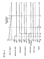
- Fig. 4 is a time-line diagram illustrating an example of the automatic engine stop by the idling stop control device 1.
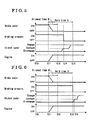
- Fig. 5 is a time-line diagram illustrating an example of the automatic start of the engine 91 by the idling stop control device 1 in a typical operation.
- Fig. 6 is a time-line diagram illustrating an example of the automatic engine start by the idling stop control device 1 when the contact operation of the clutch 92 is delayed.
- Fig. 4 is a time-line diagram illustrating an example of the automatic engine stop by the idling stop control device 1.
- FIG. 7 is a time-line diagram illustrating an example of the automatic start of the engine 91 by the idling stop control device 1 when the release of the clutch 92 is too early and the starting of the engine 91 is restricted.
- Figs. 4 to 7 share common horizontal lines of elapsed time t.
- the time-line diagram of Fig. 4 illustrates, respectively from top to bottom, the vehicle speed V, the operation amount of the accelerator pedal 911, the operation amount of the brake pedal 941, the braking pressure in the brake system 94, the operation amount of the clutch pedal 921, shift position SP of the shift lever of the transmission 93, and the operation status of the engine 91.
- the illustrated example shows that at a time t0, the shift lever is in D position for driving in a forward direction, the engine is running, the vehicle is moving with the accelerator pedal being pressed, and the vehicle speed V is gradually decreasing.
- the accelerator pedal 911 is released.
- braking force is generated by the brake pedal 941 being pressed and at the same time the clutch pedal 921 is also pressed.
- the vehicle speed V drops to the predetermined vehicle speed V0.
- the idling stop control device 1 stops the engine 91 automatically, because the conditions in Steps S1 to S6 described in Fig. 2 are satisfied.
- the pedals 911, 921, 941 are not operated and when the vehicle speed V reaches zero at a time t4, cooperative control of a brake system is initiated.
- the idling stop control device 1 actuates and controls the braking pressure generating means 945 to generate the predetermined braking force.
- the engine 91 is automatically stopped when the vehicle speed V has reached or gone under the predetermined vehicle speed V0. Because the engine 91 is stopped before the vehicle speed V reaches zero, fuel efficiency is improved compared to when an engine is automatically stopped when a vehicle is stopped. Also, because the predetermined braking force is generated when the vehicle speed V reaches zero, the rear motion of the vehicle that occurs when moving the vehicle from the temporary stop on a slope is effectively prevented, as well as the sudden acceleration is avoided whenever the engine 91 automatically starts.
- the time-line diagram of Fig. 5 describing the automatic engine start in a typical operation illustrates, respectively from top to bottom, the operation amount of the brake pedal 941, the braking pressure in the brake system 94, the operation amount of the clutch pedal 921, and the operation status of the engine 91.
- Figs. 6 and 7 illustrate graphs of the same items as in Fig. 5 .
- the brake pedal 941 is pressed, and irrespective of the amount of the brake pedal 941 pressed for operation, a predetermined braking force is generated.
- the clutch pedal 921 is pressed so that the clutch 92 is disengaged, the engine 91 is at automatic stop status and the vehicle speed V is zero.
- a shift position SP is positioned in D for driving in a forward direction.
- Step S29 As illustrated in Fig. 5 , because the braking pressure is being generated, the engine 91 is started automatically. Although the brake pedal 941 is released after the time 11, the braking pressure described in Fig. 5 is sustained because this braking pressure is a pressure generated by actuating and controlling the braking pressure generating means 945.
- the engine 91 is sustained in the automatic stop status until just before the operation amount of the brake pedal 941 is decreased.
- the engine 91 is automatically started just before the vehicle starts moving.
- the embodiment according to this disclosure omits idling duration that occurs between the time the shift lever is set to a gear position D for drive until the brake pedal 941 is released, thus improves fuel efficiency.
- the predetermined braking force is generated irrespective of the amount of the brake pedal 941 pressed for operation and sustained over the predetermined hold time A duration, sudden acceleration of the vehicle unintentional to the driver is avoided.
- the braking force is sustained until the clutch 92 comes to the contact state just before the vehicle starts moving, the rear motion that occurs when moving the vehicle from the temporary stop on a slope is prevented.
- Fig. 6 is a time-line diagram illustrating an example of the automatic engine start similar to Fig. 5 when the contact operation of the clutch 92 is delayed.
- the brake pedal 941 is released at the time t11
- the braking pressure is released at the time t15, which is a specific point in time after the hold time A duration elapses
- the clutch pedal 921 is operated at a later point in time t16 so that the clutch 92 reaches the contact state.
- the vehicle starts moving.
- Fig. 7 is a time-line diagram illustrating an example of the automatic engine start similar to Fig. 5 when the contact operation of the clutch 92 is too early.
- a starting of the engine 91 is restricted because after the brake pedal 941 is released at the time t11, the release operation of the clutch pedal 921 (or the operation of the clutch 92 to the contact state) is started at a time t12, which is a specific point in time before the allowed time B duration elapses. Because the start of the engine 91 is restricted when the clutch 92 is engaged, risks for example a sudden acceleration or an engine stall are avoided. In this situation, the braking pressure is sustained even after the hold time A duration elapses and initiates a next procedure for the automatic start of the engine 91.
- the hold time A duration and the allowed time B duration are set to initiate at the time when the decrease of the operation amount of the brake pedal 941 has started, however the initiation times may be set at a specific point in time when the brake pedal 941 is displaced to a specific position during the operation.
- several other necessary conditions may be combined to the automatic stop and the automatic start condition of the engine 91 described for the embodiment of this disclosure.
- An idling stop control device (1) adapted to connect a transmission (93) to an engine (91) to be selectively engaged via a clutch (92), automatically stops and starts the engine (91) when a predetermined condition for each is satisfied.
- a braking force sustaining means (S10, S29) generates a predetermined braking force irrespective of an operation amount of a brake operation member and a start judgment means (S21 to S28) judges satisfaction of the predetermined start condition.
- an automatic start means (S30) automatically starts the engine (91).
- a braking force release means (S34, S36) releases a predetermined braking force when a predetermined hold time (A) elapses from a specific point in time where the operation amount of the brake operation member starts decreasing or comes to zero.
- the predetermined start condition requires the clutch (92) in a disengaged state and the operation amount of the brake operation member to decrease or to become zero.
Landscapes
- Engineering & Computer Science (AREA)
- Chemical & Material Sciences (AREA)
- Combustion & Propulsion (AREA)
- Mechanical Engineering (AREA)
- Transportation (AREA)
- General Engineering & Computer Science (AREA)
- Automation & Control Theory (AREA)
- Control Of Vehicle Engines Or Engines For Specific Uses (AREA)
- Control Of Driving Devices And Active Controlling Of Vehicle (AREA)
- Output Control And Ontrol Of Special Type Engine (AREA)
- Regulating Braking Force (AREA)
Abstract
Description
- This disclosure generally relates to an idling stop control device.
- In recent years, vehicles equipped with an idling stop device are becoming common. The idling stop device automatically stops an idling of an engine when a moving vehicle comes to a temporary stop at a red signal or similar situations and automatically starts the engine when the vehicle starts moving again. The idling stop device improves fuel efficiency according to a length of time the idling is stopped. By cutting off the emission gas during an idling period, the idling stop device effectively reduces an environmental impact by reducing CO2. The idling stop device also effectively cuts off an engine noise during the idling period for pedestrians and neighborhood consideration. For the idling stop device, detecting driver's intentions with accuracy is important for controlling the engine according to the driver's intentions. An example of a control device for such an idling stop device is disclosed in
JP2002-188480A - The control device disclosed in
JP2002-188480A - As described above, the control device disclosed in
JP2002-188480A - The control device disclosed in
JP2002-188480A JP2002-188480A - Meanwhile, assuring the idling stop function with higher vehicle safety is highly important for preventing risks at the time of the automatic start of the engine, for example, an unintentional sudden start (or a sudden acceleration), an unintentional engine stop (or an engine stall), or a backward vehicle motion (or a rear motion) that occurs when moving the vehicle from the temporary stop on a slope.
- A need thus exists for an idling stop control device that improves fuel efficiency by making the idling stop period longer and enhances safety of the vehicle at the same time when the vehicle starts moving by the automatic engine start.
- According to an aspect of this disclosure, an idling stop control device, adapted to connect a transmission to an engine mounted to a vehicle to be selectively engaged via a clutch, automatically stops an engine upon satisfaction of a predetermined stop condition during an idling of the engine and automatically starts the engine upon satisfaction of a predetermined start condition when the engine is in an automatic stop state. During the automatic stop state, a braking force sustaining means generates a predetermined braking force irrespective of an operation amount of a brake operation member and a start judgment means judges satisfaction of the predetermined start condition. When the predetermined start condition is satisfied, an automatic start means automatically starts the engine. A braking force release means releases a predetermined braking force when a predetermined hold time duration elapses from a specific point in time where the operation amount of the brake operation member starts decreasing or comes to zero. The predetermined start condition requires the clutch in a disengaged state and, additionally, the operation amount of the brake operation member to decrease or to become zero.
- The decrease or a complete loss of the operation amount of the brake operation member is included as a requirement for the predetermined start condition, so that the automatic start of the engine effectively reflects a driver's intention to move. The engine is automatically stopped as long as possible and automatically started just before the vehicle starts moving, thus improves fuel efficiency. The predetermined start condition also includes the clutch in a disengaged state as a requirement, which means the engine is automatically started in a state that the transmission, driving wheels and rotating members that lie between them are disconnected. As a result, the engine start by a starter becomes more reliable and an engine stall is avoided. Furthermore, the predetermined braking force is generated irrespective of the operation amount of the brake operation member and is sustained over the predetermined hold time duration. As a result, a sudden acceleration of the vehicle unintentional to the driver is avoided.
- According to another aspect of the disclosure, the idling stop control device according to
Claim 1, further includes a start restricting means such that restricts the start of the engine despite the predetermined start condition is satisfied, when the clutch is operated to contact from a disengaged state before a predetermined allowed time duration elapses, which is a duration shorter than the predetermined hold time duration, from the specific point in time where the operation amount of the brake operation member starts decreasing or comes to zero. - The idling stop control device restricts the start of the engine when the clutch is operated to contact from a disengaged state before the predetermined allowed time duration elapses from the specific point in time where the decrease or the complete loss of the operation amount occurs in the brake operation member, despite the predetermined start condition is satisfied. In other words, when the driver is too early on a clutch engagement operation after the release of the brake operation member, the start of the engine is restricted. Because the start of the engine is restricted when the clutch is engaged, risks for example a sudden acceleration or an engine stall are avoided.
- According to a further aspect of the disclosure, the idling stop control device according to
Claim 2, further includes a movement allowing means releasing the predetermined braking force immediately when the allowed time duration elapses from the specific point in time where the operation amount of the brake operation member starts decreasing or comes to zero and when the clutch is operated to contact from a disengaged state before the predetermined hold time duration elapses. - The idling stop control device releases the predetermined braking force immediately when the allowed time duration elapses from the specific point in time where the decrease or the complete loss of the operation amount occurs in the brake operation member and when the clutch is operated to contact from the disengaged state before the hold time duration elapses. Fuel efficiency is improved because after the automatic start of the engine, the vehicle is allowed to start moving at an intended timing of the driver. Furthermore, because the braking force is sustained until the clutch comes to the contact state just before the vehicle starts moving, the rear motion that occurs when moving the vehicle from the temporary stop on a slope is prevented.
- According to another aspect of the disclosure, the idling stop control device according to any one of
Claims 1 to 3, further includes a stop judgment means judging a satisfaction of the predetermined stop condition while the vehicle is in motion, an automatic stop means stopping the engine automatically when the predetermined stop condition is satisfied, an engine-stopped-period braking force generation means generating the predetermined braking force when the vehicle speed comes to zero after the automatic stop of the engine, and the predetermined stop condition requiring a speed of the vehicle as less than or equal to a predetermined vehicle speed or a speed of the engine as less than or equal to a predetermined engine speed. - Because the predetermined stop condition requires the speed of the vehicle or the speed of the engine as less than or equal to the predetermined speed for each, the engine is automatically stopped before the vehicle comes to a complete stop, which leads to an improved fuel efficiency. Furthermore, when the vehicle speed reaches zero, a predetermined braking force is generated irrespective of the operation amount of the brake operation member. As a result, the rear motion that occurs when moving the vehicle from the temporary stop on a slope is effectively prevented, as well as a sudden acceleration is avoided whenever the engine automatically starts.
- The foregoing and additional features and characteristics of this disclosure will become more apparent from the following detailed description considered with the reference to the accompanying drawings, wherein:
-
Fig. 1 is a block diagram illustrating a functional configuration including a powertrain configuration of an embodiment of an idling stop control device equipped on a vehicle. -
Fig. 2 is a flow diagram showing a control procedure for an automatic engine stop by the idling stop control device. -
Fig. 3 is a flow diagram showing a control procedure for an automatic engine start by the idling stop control device. -
Fig. 4 is a time-line diagram illustrating an example of the automatic engine stop by the idling stop control device. -
Fig. 5 is a time-line diagram illustrating an example of the automatic engine start by the idling stop control device during a typical operation. -
Fig. 6 is a time-line diagram illustrating an example of the automatic engine start by the idling stop control device when the clutch contact operation is delayed. -
Fig. 7 is a time-line diagram illustrating an example of the automatic engine start by the idling stop control device when the clutch operation is too early and a stating of the engine is restricted. - An embodiment of an idling
stop control device 1 will be described as follows referring toFigs. 1 to 7 .Fig. 1 is a block diagram illustrating a functional configuration including a powertrain configuration of an embodiment of the idlingstop control device 1 equipped on a vehicle. Arrows inFig. 1 represent flow directions of controls, for example, measured values or commands. As shown in the block diagram, the powertrain of the vehicle includes anengine 91, aclutch 92, atransmission 93. Theengine 91 includes astarter 915 that uses a starter motor. Theclutch 92 connects theengine 91 and thetransmission 93 in a selectively engaging manner. An output shaft of thetransmission 93 is connected to driving wheels via axles. - An
accelerator pedal 911 is provided for controlling an air-fuel mixture supply amount to theengine 91. Theaccelerator pedal 911 is provided with an acceleratoropening degree sensor 912 for detecting an amount of theaccelerator pedal 911 pressed for the operations. Aclutch pedal 921 is provided for controlling the clutch 92. Theclutch pedal 921 is provided with a clutchpedal stroke sensor 922 for detecting an amount of theclutch pedal 921 pressed for the operations. The clutch 92 is of a conventional type, which is disengaged when a driver presses theclutch pedal 921, becomes a contact state and starts to be engaged when the pressed amount of theclutch pedal 21 is reduced, and is fully engaged when the pressed amount of theclutch pedal 21 is reduced to zero. Thetransmission 93 is a manual transmission in which the driver controls a shift lever to change gear positions of the transmission, for example, in D for driving in a forward direction, in R for reversing the direction, or in N for a neutral state. Thetransmission 93 includes ashift position sensor 932, which detects a shift position SP of the shift lever. - Meanwhile, the vehicle is equipped with a
brake system 94, which applies a braking force to each wheel. A conventional type brake system, which uses a braking pressure of a hydraulic fluid for applying the braking force to each wheel, may be used as thebrake system 94. Abrake pedal 941 is provided as a brake operation member for actuating thebrake system 94, and abraking switch 942 is provided for detecting an amount of thebrake pedal 941 pressed for an operation. Thebrake system 94 is equipped with a built-in braking pressure generating means 945 that operates independently from the operation of thebrake pedal 941. The braking pressure generating means 945 generates a predetermined braking force irrespective of the amount of thebrake pedal 941 pressed for the operation. An electric oil pump or an accumulator tank, for example, may be used as the braking pressure generating means 945. - The idling
stop control device 1 includes a vehiclecondition detecting means 2, an engine control means 3, and a brake control means 4. The vehiclecondition detecting means 2, the engine control means 3, and the brake control means 4 may be configured by combining an electronic control unit (ECU) and a sensor appropriately. - The vehicle
condition detecting means 2 includes an enginecondition detecting means 21 and an enginespeed detecting means 22 for detecting an operation status and a speed of theengine 91. The vehiclecondition detecting means 2 also includes a vehiclespeed detecting means 23 for detecting a traveling speed of a vehicle (or a vehicle speed). The vehiclecondition detecting means 2 receives a signal on an amount of theaccelerator pedal 911 being pressed for operation sent from the signal acceleratoropening degree sensor 912. Likewise, the vehiclecondition detecting means 2 receives a signal on an amount of theclutch pedal 921 being pressed for operation from the clutchpedal stroke sensor 922, a signal on a shift position SP of the shift lever of thetransmission 93 from theshift position sensor 932, and a signal on an amount of thebrake pedal 941 being pressed for operation from thebraking switch 942. - The engine control means 3 receives information on the operation status and the speed of the
engine 91, the traveling speed of the vehicle, the amount of each pedal 911, 921, 941 pressed for operation, and the shift position SP of the shift lever of thetransmission 93 from the vehiclecondition detecting means 2. According to the information received, the engine control means 3 judges whether the predetermined stop condition, which automatically stops theengine 91, and the predetermined start condition, which automatically starts theengine 91, are satisfied or not. Further, according to the judgment results, the engine control means 3 sends necessary control signals, which automatically stop and automatically start theengine 91, to theengine 91 and thestarter 915. According to the received control signals, theengine 91 and thestarter 915 process an automatic start and an automatic stop of theengine 91. - Like the engine control means 3, the brake control means 4 receives each of the aforementioned information from the vehicle
condition detecting means 2. The brake control means 4 calculates amount of a necessary braking force according to the received information and sends a control signal to thebrake system 94. Thebrake system 94 generates and applies the necessary braking force to each wheel according to the received control signal. To apply the braking force to each wheel, the brake control means 4 may control the braking force as a whole, or the braking force applied to each wheel may be controlled by a combination of the brake control means 4 and a direct actuation of thebrake system 94 by thebrake pedal 941, which generates the braking force in part. - Next, procedures for each function of the idling
stop control device 1 to function will be described referring to flow diagrams.Fig. 2 is a flow diagram showing a control procedure for an automatic stop of theengine 91 by the idlingstop control device 1.Fig. 3 is a flow diagram showing a control procedure for an automatic start of theengine 91 by the idlingstop control device 1. - Step S1 in
Fig. 2 for the automatic stop procedure postulates that theengine 91 is in motion. In other words, when theengine 91 is stopped by an operation of a driver and not by an idling stop function, the idlingstop control device 1 does not function. When theengine 91 is in motion, the idlingstop control device 1 judges whether the traveling speed of the vehicle, or a vehicle speed V, is less than or equal to a predetermined speed V0 or not in Step S2. The predetermined speed V0 is determined to be equal to the vehicle speed when theengine 91 maintains an idling state engine speed. When the vehicle speed V condition is satisfied, release of theaccelerator pedal 911 condition is judged in Step S3, pressing of thebrake pedal 941 is judged in Step S4, and when the conditions of Steps from S1 to S4 are satisfied, the procedure proceeds to Step S5. - I n Step S5, whether the
clutch pedal 921 is pressed or not, or in other words whether the clutch 92 is engaged or disengaged, is judged. When the clutch is disengaged, the procedure proceeds to Step S6 and the procedure proceeds to Step S7 when the clutch is engaged. In Step S6. a shift position SP of the shift lever of thetransmission 93 is identified. When the shift position SP is in a position other than reverse R (a gear position R for driving backward), the procedure proceeds to Step S8 and stops theengine 91 automatically, In Step S7, the shift position SP of the shift lever of thetransmission 93 is identified. When the shift position SP is in neutral N, the procedure proceeds to Step S8, which stops theengine 91 automatically. - When any of the conditions in Steps S2 to S7 are not satisfied, the procedure goes back to Step S1 in any step. Steps S2 to S7 serve as stop judgment means and Step S8 serves as an automatic stop means. In Step S2, the traveling speed of the vehicle (vehicle speed V) to be less than or equal to the predetermined speed V0 is defined as a requirement for the automatic stop of the
engine 91. In Step S6, when the clutch 92 is disengaged and the shift position SP of the shift lever is in reverse R (the gear position R for driving backward), the vehicle is assumed to be in a back-in parking state, therefore, to avoid an operational confusion, the procedure does not proceed to the automatic stop of theengine 91. Also in Step S7, when the clutch 92 is engaged and the shift position SP of the shift lever is in a position other than neutral N, assuming the driver has an intention to accelerate again or to move the vehicle in some other way, the procedure does not proceed to the automatic stop of theengine 91. - After the automatic stop of the
engine 91 in Step S8, the procedure proceeds to Step S9, which waits for the vehicle speed V to be reduced to zero. When the vehicle speed V reaches zero, a predetermined braking force is generated by a cooperative brake control in Step S10. In other words, the braking pressure generating means 945 is actuated and controlled to generate a predetermined braking force irrespective of the amount of thebrake pedal 941 pressed for operation. Steps S9 and S10 serve as engine-stopped-period braking force generation means. - The automatic start of the
engine 91 begins with a confirmation of the vehicle speed V in Step S21 inFig. 3 for describing the flow of an automatic start procedure. When the vehicle speed V is not zero, the procedure proceeds to Step S22 and starts theengine 91 while generating speed by a conventional method. A situation example for proceeding from Step S21 to Step S22 is when a signal Is changed to green while the vehicle is coming to a temporary stop at a red signal and the driver decides to accelerate the vehicle again. Step S9 inFig. 2 is in the situation similar to that of Step S21. When the vehicle speed V is zero in Step S21. then the procedure proceeds to Step S23 to judge whether theaccelerator pedal 911 is released or not. When the condition is satisfied in Step S23, the procedure proceeds to Step S24 and when the condition is not satisfied, the procedure goes back to Step S21. In Step S24, when the shift position SP of the shift lever of thetransmission 93 is in a position other than neutral N, assuming the driver has the intention to move the vehicle, the procedure proceeds to Step S25. When the shift position SP in Step S24 is in neutral N, the procedure goes back to Step S21. In next Step S25, when the shift position SP of the shift lever is in reverse R, the procedure proceeds to Step S26 and immediately starts theengine 91, as shifting to reverse R indicates an intention to move the vehicle. - In Step S25, when the shift position SP of the shift lever is in D for driving in a forward direction, the procedure proceeds to Step S27, the step which judges whether the
clutch pedal 921 is pressed or not, or in other words whether the clutch 92 is engaged or disengaged. When the clutch is disengaged, the procedure proceeds to Step S28 and the procedure goes back to Step S21 when the clutch is engaged. In Step S28, whether an operation amount of thebrake pedal 941 is decreasing or not is judged. When the condition is satisfied in Step S28, the procedure proceeds to Step S29 and when the condition is not satisfied, the procedure goes back to Step S21. In Step S29, whether or not a predetermined braking pressure is sustained at the wheels is determined. When more braking pressure is necessary, the braking pressure generating means 945 is actuated and is controlled to generate the braking pressure necessary to sustain the predetermined braking pressure. Normally, the predetermined braking pressure is generated and sustained in Step S10 of the procedure for the automatic stop of theengine 91, described inFig. 2 . In next Step S30, thestarter 915 initiates the automatic start of theengine 91. - When conditions in Steps S27 and S28 are not satisfied, the procedure goes back to the Step S21. In other words, the clutch 92 being disengaged and the decrease of the operation amount of the brake pedal 41 are defined as requirements for the automatic start of the
engine 91. Steps S21 to S28 serve as start judgment means, Step S10 inFig. 2 and Step S29 serve as braking force sustaining means, and Step S30 serves as a automatic start means. - After the automatic start of the
engine 91 in Step S30, Step S31 judges whether or not a release operation of theclutch pedal 921 has started within an allowed time B duration, that is, in other words, whether or not the clutch 92 has operated to contact from the disengaged state. The allowed time B duration is initiated when the decrease of the operation amount of thebrake pedal 941 has started. Considering that starting of theengine 91 may take some time, the allowed time B duration is set to end after theengine 91 is completely in motion and before the clutch 92 makes contact prior to the engagement. When the release operation of theclutch pedal 921 is initiated within the allowed time B duration, the procedure proceeds to Step S32 and stops thestarter 915 then stops theengine 91 in following Step S33. After Step S33, the procedure goes back to Step S21 and initiates the procedure for the automatic start of theengine 91 once again. A situation example for proceeding from Step S32 to Step S21 via Step S33 is when a driver releases the clutch pedal 921 (or engages the clutch 92) too early after the release of the brake pedal 941 (referring to Step S28). Step S32 and Step S33 serve as start restricting means. - In Step S31, when the
clutch pedal 921 is not operated within the allowed time B duration, the procedure proceeds to Step S34. At this point, the clutch 92 is operated to a contact state, and when the clutch 92 reaches a contact state, the procedure proceeds to Step S36 and immediately releases the predetermined braking pressure, which allows the vehicle to move. By sustaining the braking pressure until the clutch 92 reaches a contact state, a sudden acceleration or a rear motion of the vehicle are prevented. Steps S34 and S36 serve as movement allowing means. - While waiting for the contact state in Step S34, an elapsed time is being measured in Step S35. When the elapsed time reaches a hold time A duration, the procedure proceeds to Step 36 and the predetermined braking pressure is released, so that the vehicle may start moving at any time intended. When the driver engages the clutch 92, the vehicle starts moving. The hold time A duration is initiated when the decrease of the operation amount of the
brake pedal 941 starts in Step S28 and is set to end after the duration longer than the time it takes for the clutch 92 to reach the contact state in a typical operation. - How an embodiment of the idling
stop control device 1 behaves, works, and an effectiveness thereof is described next referring to examples.Fig. 4 is a time-line diagram illustrating an example of the automatic engine stop by the idlingstop control device 1.Fig. 5 is a time-line diagram illustrating an example of the automatic start of theengine 91 by the idlingstop control device 1 in a typical operation.Fig. 6 is a time-line diagram illustrating an example of the automatic engine start by the idlingstop control device 1 when the contact operation of the clutch 92 is delayed.Fig. 7 is a time-line diagram illustrating an example of the automatic start of theengine 91 by the idlingstop control device 1 when the release of the clutch 92 is too early and the starting of theengine 91 is restricted.Figs. 4 to 7 share common horizontal lines of elapsed time t. - The time-line diagram of
Fig. 4 illustrates, respectively from top to bottom, the vehicle speed V, the operation amount of theaccelerator pedal 911, the operation amount of thebrake pedal 941, the braking pressure in thebrake system 94, the operation amount of theclutch pedal 921, shift position SP of the shift lever of thetransmission 93, and the operation status of theengine 91. The illustrated example shows that at a time t0, the shift lever is in D position for driving in a forward direction, the engine is running, the vehicle is moving with the accelerator pedal being pressed, and the vehicle speed V is gradually decreasing. At a time t1, theaccelerator pedal 911 is released. At a time t2, braking force is generated by thebrake pedal 941 being pressed and at the same time theclutch pedal 921 is also pressed. At a time t3, the vehicle speed V drops to the predetermined vehicle speed V0. At this time, the idlingstop control device 1 stops theengine 91 automatically, because the conditions in Steps S1 to S6 described inFig. 2 are satisfied. - After the time t3, the
pedals stop control device 1 actuates and controls the braking pressure generating means 945 to generate the predetermined braking force. - According to the embodiment of this disclosure, the
engine 91 is automatically stopped when the vehicle speed V has reached or gone under the predetermined vehicle speed V0. Because theengine 91 is stopped before the vehicle speed V reaches zero, fuel efficiency is improved compared to when an engine is automatically stopped when a vehicle is stopped. Also, because the predetermined braking force is generated when the vehicle speed V reaches zero, the rear motion of the vehicle that occurs when moving the vehicle from the temporary stop on a slope is effectively prevented, as well as the sudden acceleration is avoided whenever theengine 91 automatically starts. - The time-line diagram of
Fig. 5 describing the automatic engine start in a typical operation illustrates, respectively from top to bottom, the operation amount of thebrake pedal 941, the braking pressure in thebrake system 94, the operation amount of theclutch pedal 921, and the operation status of theengine 91.Figs. 6 and7 illustrate graphs of the same items as inFig. 5 . In the example illustrated inFig. 5 , at a time t10, thebrake pedal 941 is pressed, and irrespective of the amount of thebrake pedal 941 pressed for operation, a predetermined braking force is generated. At the same time, theclutch pedal 921 is pressed so that the clutch 92 is disengaged, theengine 91 is at automatic stop status and the vehicle speed V is zero. At this time, a shift position SP is positioned in D for driving in a forward direction. - At at time t11, when the driver releases the
brake pedal 941, because the conditions in Step S21 thru Step S28 inFig. 3 are satisfied, the procedure proceeds to Step S29. As illustrated inFig. 5 , because the braking pressure is being generated, theengine 91 is started automatically. Although thebrake pedal 941 is released after the time 11, the braking pressure described inFig. 5 is sustained because this braking pressure is a pressure generated by actuating and controlling the braking pressure generating means 945. At a time t14, which is a specific point in time after the allowed time B duration elapses (at a time t13) and before the hold time A duration also elapses (at a time t15), when theclutch pedal 921 is operated and the clutch 92 is operated to a contact state, the braking pressure is released and the vehicle starts moving. - According to the embodiment of this disclosure, the
engine 91 is sustained in the automatic stop status until just before the operation amount of thebrake pedal 941 is decreased. In other words, theengine 91 is automatically started just before the vehicle starts moving. Compared to when theengine 91 is automatically started at the timing of the shift lever of thetransmission 93 set to a gear position D for drive, the embodiment according to this disclosure omits idling duration that occurs between the time the shift lever is set to a gear position D for drive until thebrake pedal 941 is released, thus improves fuel efficiency. Also, because the predetermined braking force is generated irrespective of the amount of thebrake pedal 941 pressed for operation and sustained over the predetermined hold time A duration, sudden acceleration of the vehicle unintentional to the driver is avoided. Furthermore, because the braking force is sustained until the clutch 92 comes to the contact state just before the vehicle starts moving, the rear motion that occurs when moving the vehicle from the temporary stop on a slope is prevented. -
Fig. 6 is a time-line diagram illustrating an example of the automatic engine start similar toFig. 5 when the contact operation of the clutch 92 is delayed. InFig. 6 , after thebrake pedal 941 is released at the time t11, the braking pressure is released at the time t15, which is a specific point in time after the hold time A duration elapses, then theclutch pedal 921 is operated at a later point in time t16 so that the clutch 92 reaches the contact state. As illustrated inFig. 6 , even though the operation of the clutch 92 was delayed, followed by the automatic start of theengine 91, the vehicle starts moving. -
Fig. 7 is a time-line diagram illustrating an example of the automatic engine start similar toFig. 5 when the contact operation of the clutch 92 is too early. InFig. 7 , a starting of theengine 91 is restricted because after thebrake pedal 941 is released at the time t11, the release operation of the clutch pedal 921 (or the operation of the clutch 92 to the contact state) is started at a time t12, which is a specific point in time before the allowed time B duration elapses. Because the start of theengine 91 is restricted when the clutch 92 is engaged, risks for example a sudden acceleration or an engine stall are avoided. In this situation, the braking pressure is sustained even after the hold time A duration elapses and initiates a next procedure for the automatic start of theengine 91. - In the embodiment of this disclosure, the hold time A duration and the allowed time B duration are set to initiate at the time when the decrease of the operation amount of the
brake pedal 941 has started, however the initiation times may be set at a specific point in time when thebrake pedal 941 is displaced to a specific position during the operation. Also, several other necessary conditions may be combined to the automatic stop and the automatic start condition of theengine 91 described for the embodiment of this disclosure. Moreover, further applications or variations are possible for the embodiment of this disclosure.
An idling stop control device (1), adapted to connect a transmission (93) to an engine (91) to be selectively engaged via a clutch (92), automatically stops and starts the engine (91) when a predetermined condition for each is satisfied. During the automatic stop state, a braking force sustaining means (S10, S29) generates a predetermined braking force irrespective of an operation amount of a brake operation member and a start judgment means (S21 to S28) judges satisfaction of the predetermined start condition. When the predetermined start condition is satisfied, an automatic start means (S30) automatically starts the engine (91). A braking force release means (S34, S36) releases a predetermined braking force when a predetermined hold time (A) elapses from a specific point in time where the operation amount of the brake operation member starts decreasing or comes to zero. The predetermined start condition requires the clutch (92) in a disengaged state and the operation amount of the brake operation member to decrease or to become zero.
Claims (4)
- An idling stop control device (1), adapted to connect a transmission (93) to an engine (91) mounted to a vehicle to be selectively engaged via a clutch (92), for automatically stopping an engine (91) upon satisfaction of a predetermined stop condition during an idling of the engine (91) and for automatically starting the engine (91) upon satisfaction of a predetermined start condition when the engine (91) is in an automatic stop state, comprising:a braking force sustaining means (S10, S29) generating a predetermined braking force irrespective of an operation amount of a brake operation member during the automatic stop state;a start judgment means (S21 to S28) judging satisfaction of the predetermined start condition during the automatic stop state;an automatic start means (S30) automatically starting the engine (91) when the predetermined start condition is satisfied;a braking force release means (S34, S36) releasing a predetermined braking force when a predetermined hold time (A) duration elapses from a specific point in time where the operation amount of the brake operation member starts decreasing or comes to zero; andthe predetermined start condition requiring the clutch (92) in a disengaged state and, additionally, the operation amount of the brake operation member to decrease or to become zero.
- The idling stop control device (1) according to Claim 1, further comprising:a start restricting means (S32, S33) such that restricts the start of the engine (91) despite the predetermined start condition is satisfied, when the clutch (92) is operated to contact from a disengaged state before a predetermined allowed time (B) duration elapses, which is a duration shorter than the predetermined hold time (A) duration, from the specific point in time where the operation amount of the brake operation member starts decreasing or comes to zero.
- The idling stop control device (1) according to Claim 2, further comprising:a movement allowing means (S34, S36) releasing the predetermined braking force immediately when the allowed time (B) duration elapses from the specific point in time where the operation amount of the brake operation member starts decreasing or comes to zero and when the clutch (92) is operated to contact from a disengaged state before the predetermined hold time (A) duration elapses.
- The idling stop control device (1) according to any one of Claims 1 to 3, further comprising:a stop judgment means (S2 to S7) judging a satisfaction of the predetermined stop condition while the vehicle is in motion;an automatic stop means (S8) stopping the engine (91) automatically when the predetermined stop condition is satisfied;an engine-stopped-period braking force generation means (S9, S10) generating the predetermined braking force when the vehicle speed comes to zero after the automatic stop of the engine (91); andthe predetermined stop condition requiring a speed of the vehicle as less than or equal to a predetermined vehicle speed or a speed of the engine (91) as less than or equal to a predetermined engine speed.
Applications Claiming Priority (1)
| Application Number | Priority Date | Filing Date | Title |
|---|---|---|---|
| JP2010242296A JP5682229B2 (en) | 2010-10-28 | 2010-10-28 | Idling stop control device |
Publications (3)
| Publication Number | Publication Date |
|---|---|
| EP2447125A2 true EP2447125A2 (en) | 2012-05-02 |
| EP2447125A3 EP2447125A3 (en) | 2013-05-22 |
| EP2447125B1 EP2447125B1 (en) | 2014-05-14 |
Family
ID=45001644
Family Applications (1)
| Application Number | Title | Priority Date | Filing Date |
|---|---|---|---|
| EP20110186838 Not-in-force EP2447125B1 (en) | 2010-10-28 | 2011-10-27 | Idling stop control device |
Country Status (2)
| Country | Link |
|---|---|
| EP (1) | EP2447125B1 (en) |
| JP (1) | JP5682229B2 (en) |
Cited By (2)
| Publication number | Priority date | Publication date | Assignee | Title |
|---|---|---|---|---|
| CN104153897A (en) * | 2013-05-14 | 2014-11-19 | 通用汽车环球科技运作有限责任公司 | Engine start control system and method |
| GB2582956A (en) * | 2019-04-10 | 2020-10-14 | Ford Global Tech Llc | Improvements to a rolling start-stop system |
Families Citing this family (3)
| Publication number | Priority date | Publication date | Assignee | Title |
|---|---|---|---|---|
| US10252728B2 (en) * | 2015-10-30 | 2019-04-09 | Nissan Motor Co., Ltd. | Information providing method for vehicle and information providing device for vehicle |
| JP6652867B2 (en) * | 2016-03-18 | 2020-02-26 | ルネサスエレクトロニクス株式会社 | Motorcycle, control method therefor, and semiconductor device |
| CN105946601B (en) * | 2016-05-05 | 2019-01-29 | 北京新能源汽车股份有限公司 | Range-extending type electric automobile and power generation control method thereof |
Citations (1)
| Publication number | Priority date | Publication date | Assignee | Title |
|---|---|---|---|---|
| JP2002188480A (en) | 2000-12-18 | 2002-07-05 | Suzuki Motor Corp | Automatic stop / start control system for engine |
Family Cites Families (9)
| Publication number | Priority date | Publication date | Assignee | Title |
|---|---|---|---|---|
| JP3775112B2 (en) * | 1999-03-04 | 2006-05-17 | トヨタ自動車株式会社 | Control device for restarting vehicle engine |
| JP3663962B2 (en) * | 1999-03-16 | 2005-06-22 | トヨタ自動車株式会社 | Control device for restarting vehicle engine |
| JP2001047987A (en) * | 1999-08-06 | 2001-02-20 | Honda Motor Co Ltd | Brake force holding device |
| JP3711894B2 (en) * | 2001-06-08 | 2005-11-02 | 三菱ふそうトラック・バス株式会社 | Engine restart control device |
| DE10317501B4 (en) * | 2003-04-16 | 2015-06-03 | Daimler Ag | Method for operating a motor vehicle |
| JP4461721B2 (en) * | 2003-07-02 | 2010-05-12 | 日産自動車株式会社 | Idle stop control device for vehicle |
| US7484816B2 (en) * | 2005-11-23 | 2009-02-03 | Honda Motor Co., Ltd. | Vehicle control apparatus |
| JP2010053764A (en) * | 2008-08-28 | 2010-03-11 | Mazda Motor Corp | Vehicle control device and method for controlling the same |
| KR101163182B1 (en) * | 2009-02-27 | 2012-07-06 | 가부시키가이샤 덴소 | System for restarting internal combustion engine when engine restart condition is met |
-
2010
- 2010-10-28 JP JP2010242296A patent/JP5682229B2/en not_active Expired - Fee Related
-
2011
- 2011-10-27 EP EP20110186838 patent/EP2447125B1/en not_active Not-in-force
Patent Citations (1)
| Publication number | Priority date | Publication date | Assignee | Title |
|---|---|---|---|---|
| JP2002188480A (en) | 2000-12-18 | 2002-07-05 | Suzuki Motor Corp | Automatic stop / start control system for engine |
Cited By (3)
| Publication number | Priority date | Publication date | Assignee | Title |
|---|---|---|---|---|
| CN104153897A (en) * | 2013-05-14 | 2014-11-19 | 通用汽车环球科技运作有限责任公司 | Engine start control system and method |
| GB2582956A (en) * | 2019-04-10 | 2020-10-14 | Ford Global Tech Llc | Improvements to a rolling start-stop system |
| GB2582956B (en) * | 2019-04-10 | 2023-11-22 | Ford Global Tech Llc | Improvements to a rolling start-stop system |
Also Published As
| Publication number | Publication date |
|---|---|
| JP2012092775A (en) | 2012-05-17 |
| JP5682229B2 (en) | 2015-03-11 |
| EP2447125B1 (en) | 2014-05-14 |
| EP2447125A3 (en) | 2013-05-22 |
Similar Documents
| Publication | Publication Date | Title |
|---|---|---|
| US8849534B2 (en) | Vehicle control system controlling exertion of braking force on wheel | |
| JP5872072B2 (en) | Improvements in emissions control of internal combustion engines. | |
| CN106574713B (en) | Automatic transmission control device | |
| EP2447125B1 (en) | Idling stop control device | |
| US11041451B2 (en) | Internal combustion engine control method and internal combustion engine control device | |
| JP6241424B2 (en) | Vehicle control device | |
| JP2014184879A (en) | Controller for vehicle | |
| JP2014101112A (en) | Vehicular brake safety device | |
| CN103608228A (en) | Method for accelerating a vehicle and hybrid vehicle | |
| US20160236674A1 (en) | Control device of hybrid vehicle including multi-stage automatic transmission | |
| EP3335956A2 (en) | Controller for vehicle | |
| US20200318736A1 (en) | Control device and control method for vehicle including continuously variable transmission | |
| CN101934790B (en) | The starting that the starting/stopping of vehicle controls stops | |
| JP2012040899A (en) | Vehicular brake holding force control device | |
| KR102386571B1 (en) | Method for automatically switching a motor vehicle to freewheel mode | |
| JP2004125001A (en) | Clutch controller for automatic transmission of vehicle | |
| JP6582685B2 (en) | Vehicle travel control method and vehicle travel control device | |
| JP6366007B2 (en) | Vehicle control device | |
| JP2005112021A (en) | Vehicular start control device | |
| JP2004052919A (en) | Backward movement preventing device of vehicle | |
| EP3715610B1 (en) | Internal combustion engine control method and internal combustion engine control device | |
| JP2017067205A (en) | Control device for vehicle | |
| JP2017048876A (en) | Vehicle neutral control device | |
| CN113942487A (en) | A kind of downshift control method, device and electric vehicle | |
| JP2009524544A (en) | Car drive train |
Legal Events
| Date | Code | Title | Description |
|---|---|---|---|
| PUAI | Public reference made under article 153(3) epc to a published international application that has entered the european phase |
Free format text: ORIGINAL CODE: 0009012 |
|
| AK | Designated contracting states |
Kind code of ref document: A2 Designated state(s): AL AT BE BG CH CY CZ DE DK EE ES FI FR GB GR HR HU IE IS IT LI LT LU LV MC MK MT NL NO PL PT RO RS SE SI SK SM TR |
|
| AX | Request for extension of the european patent |
Extension state: BA ME |
|
| PUAL | Search report despatched |
Free format text: ORIGINAL CODE: 0009013 |
|
| AK | Designated contracting states |
Kind code of ref document: A3 Designated state(s): AL AT BE BG CH CY CZ DE DK EE ES FI FR GB GR HR HU IE IS IT LI LT LU LV MC MK MT NL NO PL PT RO RS SE SI SK SM TR |
|
| AX | Request for extension of the european patent |
Extension state: BA ME |
|
| RIC1 | Information provided on ipc code assigned before grant |
Ipc: B60W 10/02 20060101ALI20130416BHEP Ipc: B60W 10/06 20060101ALI20130416BHEP Ipc: B60W 30/18 20120101AFI20130416BHEP Ipc: B60W 10/184 20120101ALI20130416BHEP |
|
| 17P | Request for examination filed |
Effective date: 20130621 |
|
| RBV | Designated contracting states (corrected) |
Designated state(s): AL AT BE BG CH CY CZ DE DK EE ES FI FR GB GR HR HU IE IS IT LI LT LU LV MC MK MT NL NO PL PT RO RS SE SI SK SM TR |
|
| GRAP | Despatch of communication of intention to grant a patent |
Free format text: ORIGINAL CODE: EPIDOSNIGR1 |
|
| RIC1 | Information provided on ipc code assigned before grant |
Ipc: B60W 10/06 20060101ALI20131108BHEP Ipc: B60W 10/184 20120101ALI20131108BHEP Ipc: B60W 30/18 20120101AFI20131108BHEP Ipc: B60W 10/02 20060101ALI20131108BHEP |
|
| INTG | Intention to grant announced |
Effective date: 20131205 |
|
| GRAS | Grant fee paid |
Free format text: ORIGINAL CODE: EPIDOSNIGR3 |
|
| GRAA | (expected) grant |
Free format text: ORIGINAL CODE: 0009210 |
|
| AK | Designated contracting states |
Kind code of ref document: B1 Designated state(s): AL AT BE BG CH CY CZ DE DK EE ES FI FR GB GR HR HU IE IS IT LI LT LU LV MC MK MT NL NO PL PT RO RS SE SI SK SM TR |
|
| REG | Reference to a national code |
Ref country code: GB Ref legal event code: FG4D |
|
| REG | Reference to a national code |
Ref country code: AT Ref legal event code: REF Ref document number: 668036 Country of ref document: AT Kind code of ref document: T Effective date: 20140615 |
|
| REG | Reference to a national code |
Ref country code: IE Ref legal event code: FG4D |
|
| REG | Reference to a national code |
Ref country code: DE Ref legal event code: R096 Ref document number: 602011006881 Country of ref document: DE Effective date: 20140703 |
|
| REG | Reference to a national code |
Ref country code: NL Ref legal event code: VDEP Effective date: 20140514 Ref country code: AT Ref legal event code: MK05 Ref document number: 668036 Country of ref document: AT Kind code of ref document: T Effective date: 20140514 |
|
| REG | Reference to a national code |
Ref country code: LT Ref legal event code: MG4D |
|
| PG25 | Lapsed in a contracting state [announced via postgrant information from national office to epo] |
Ref country code: LT Free format text: LAPSE BECAUSE OF FAILURE TO SUBMIT A TRANSLATION OF THE DESCRIPTION OR TO PAY THE FEE WITHIN THE PRESCRIBED TIME-LIMIT Effective date: 20140514 Ref country code: GR Free format text: LAPSE BECAUSE OF FAILURE TO SUBMIT A TRANSLATION OF THE DESCRIPTION OR TO PAY THE FEE WITHIN THE PRESCRIBED TIME-LIMIT Effective date: 20140815 Ref country code: FI Free format text: LAPSE BECAUSE OF FAILURE TO SUBMIT A TRANSLATION OF THE DESCRIPTION OR TO PAY THE FEE WITHIN THE PRESCRIBED TIME-LIMIT Effective date: 20140514 Ref country code: IS Free format text: LAPSE BECAUSE OF FAILURE TO SUBMIT A TRANSLATION OF THE DESCRIPTION OR TO PAY THE FEE WITHIN THE PRESCRIBED TIME-LIMIT Effective date: 20140914 Ref country code: NO Free format text: LAPSE BECAUSE OF FAILURE TO SUBMIT A TRANSLATION OF THE DESCRIPTION OR TO PAY THE FEE WITHIN THE PRESCRIBED TIME-LIMIT Effective date: 20140814 Ref country code: CY Free format text: LAPSE BECAUSE OF FAILURE TO SUBMIT A TRANSLATION OF THE DESCRIPTION OR TO PAY THE FEE WITHIN THE PRESCRIBED TIME-LIMIT Effective date: 20140514 |
|
| PG25 | Lapsed in a contracting state [announced via postgrant information from national office to epo] |
Ref country code: LV Free format text: LAPSE BECAUSE OF FAILURE TO SUBMIT A TRANSLATION OF THE DESCRIPTION OR TO PAY THE FEE WITHIN THE PRESCRIBED TIME-LIMIT Effective date: 20140514 Ref country code: RS Free format text: LAPSE BECAUSE OF FAILURE TO SUBMIT A TRANSLATION OF THE DESCRIPTION OR TO PAY THE FEE WITHIN THE PRESCRIBED TIME-LIMIT Effective date: 20140514 Ref country code: PL Free format text: LAPSE BECAUSE OF FAILURE TO SUBMIT A TRANSLATION OF THE DESCRIPTION OR TO PAY THE FEE WITHIN THE PRESCRIBED TIME-LIMIT Effective date: 20140514 Ref country code: ES Free format text: LAPSE BECAUSE OF FAILURE TO SUBMIT A TRANSLATION OF THE DESCRIPTION OR TO PAY THE FEE WITHIN THE PRESCRIBED TIME-LIMIT Effective date: 20140514 Ref country code: AT Free format text: LAPSE BECAUSE OF FAILURE TO SUBMIT A TRANSLATION OF THE DESCRIPTION OR TO PAY THE FEE WITHIN THE PRESCRIBED TIME-LIMIT Effective date: 20140514 Ref country code: HR Free format text: LAPSE BECAUSE OF FAILURE TO SUBMIT A TRANSLATION OF THE DESCRIPTION OR TO PAY THE FEE WITHIN THE PRESCRIBED TIME-LIMIT Effective date: 20140514 Ref country code: SE Free format text: LAPSE BECAUSE OF FAILURE TO SUBMIT A TRANSLATION OF THE DESCRIPTION OR TO PAY THE FEE WITHIN THE PRESCRIBED TIME-LIMIT Effective date: 20140514 |
|
| PG25 | Lapsed in a contracting state [announced via postgrant information from national office to epo] |
Ref country code: PT Free format text: LAPSE BECAUSE OF FAILURE TO SUBMIT A TRANSLATION OF THE DESCRIPTION OR TO PAY THE FEE WITHIN THE PRESCRIBED TIME-LIMIT Effective date: 20140915 |
|
| PG25 | Lapsed in a contracting state [announced via postgrant information from national office to epo] |
Ref country code: DK Free format text: LAPSE BECAUSE OF FAILURE TO SUBMIT A TRANSLATION OF THE DESCRIPTION OR TO PAY THE FEE WITHIN THE PRESCRIBED TIME-LIMIT Effective date: 20140514 Ref country code: RO Free format text: LAPSE BECAUSE OF FAILURE TO SUBMIT A TRANSLATION OF THE DESCRIPTION OR TO PAY THE FEE WITHIN THE PRESCRIBED TIME-LIMIT Effective date: 20140514 Ref country code: CZ Free format text: LAPSE BECAUSE OF FAILURE TO SUBMIT A TRANSLATION OF THE DESCRIPTION OR TO PAY THE FEE WITHIN THE PRESCRIBED TIME-LIMIT Effective date: 20140514 Ref country code: BE Free format text: LAPSE BECAUSE OF FAILURE TO SUBMIT A TRANSLATION OF THE DESCRIPTION OR TO PAY THE FEE WITHIN THE PRESCRIBED TIME-LIMIT Effective date: 20140514 Ref country code: SK Free format text: LAPSE BECAUSE OF FAILURE TO SUBMIT A TRANSLATION OF THE DESCRIPTION OR TO PAY THE FEE WITHIN THE PRESCRIBED TIME-LIMIT Effective date: 20140514 Ref country code: EE Free format text: LAPSE BECAUSE OF FAILURE TO SUBMIT A TRANSLATION OF THE DESCRIPTION OR TO PAY THE FEE WITHIN THE PRESCRIBED TIME-LIMIT Effective date: 20140514 |
|
| REG | Reference to a national code |
Ref country code: DE Ref legal event code: R097 Ref document number: 602011006881 Country of ref document: DE |
|
| PG25 | Lapsed in a contracting state [announced via postgrant information from national office to epo] |
Ref country code: NL Free format text: LAPSE BECAUSE OF FAILURE TO SUBMIT A TRANSLATION OF THE DESCRIPTION OR TO PAY THE FEE WITHIN THE PRESCRIBED TIME-LIMIT Effective date: 20140514 |
|
| PLBE | No opposition filed within time limit |
Free format text: ORIGINAL CODE: 0009261 |
|
| STAA | Information on the status of an ep patent application or granted ep patent |
Free format text: STATUS: NO OPPOSITION FILED WITHIN TIME LIMIT |
|
| 26N | No opposition filed |
Effective date: 20150217 |
|
| PG25 | Lapsed in a contracting state [announced via postgrant information from national office to epo] |
Ref country code: IT Free format text: LAPSE BECAUSE OF FAILURE TO SUBMIT A TRANSLATION OF THE DESCRIPTION OR TO PAY THE FEE WITHIN THE PRESCRIBED TIME-LIMIT Effective date: 20140514 |
|
| REG | Reference to a national code |
Ref country code: DE Ref legal event code: R097 Ref document number: 602011006881 Country of ref document: DE Effective date: 20150217 |
|
| PG25 | Lapsed in a contracting state [announced via postgrant information from national office to epo] |
Ref country code: LU Free format text: LAPSE BECAUSE OF FAILURE TO SUBMIT A TRANSLATION OF THE DESCRIPTION OR TO PAY THE FEE WITHIN THE PRESCRIBED TIME-LIMIT Effective date: 20141027 Ref country code: MC Free format text: LAPSE BECAUSE OF FAILURE TO SUBMIT A TRANSLATION OF THE DESCRIPTION OR TO PAY THE FEE WITHIN THE PRESCRIBED TIME-LIMIT Effective date: 20140514 |
|
| REG | Reference to a national code |
Ref country code: CH Ref legal event code: PL |
|
| REG | Reference to a national code |
Ref country code: IE Ref legal event code: MM4A |
|
| PG25 | Lapsed in a contracting state [announced via postgrant information from national office to epo] |
Ref country code: CH Free format text: LAPSE BECAUSE OF NON-PAYMENT OF DUE FEES Effective date: 20141031 Ref country code: SI Free format text: LAPSE BECAUSE OF FAILURE TO SUBMIT A TRANSLATION OF THE DESCRIPTION OR TO PAY THE FEE WITHIN THE PRESCRIBED TIME-LIMIT Effective date: 20140514 Ref country code: LI Free format text: LAPSE BECAUSE OF NON-PAYMENT OF DUE FEES Effective date: 20141031 |
|
| PG25 | Lapsed in a contracting state [announced via postgrant information from national office to epo] |
Ref country code: IE Free format text: LAPSE BECAUSE OF NON-PAYMENT OF DUE FEES Effective date: 20141027 |
|
| PG25 | Lapsed in a contracting state [announced via postgrant information from national office to epo] |
Ref country code: SM Free format text: LAPSE BECAUSE OF FAILURE TO SUBMIT A TRANSLATION OF THE DESCRIPTION OR TO PAY THE FEE WITHIN THE PRESCRIBED TIME-LIMIT Effective date: 20140514 |
|
| GBPC | Gb: european patent ceased through non-payment of renewal fee |
Effective date: 20151027 |
|
| PG25 | Lapsed in a contracting state [announced via postgrant information from national office to epo] |
Ref country code: BG Free format text: LAPSE BECAUSE OF FAILURE TO SUBMIT A TRANSLATION OF THE DESCRIPTION OR TO PAY THE FEE WITHIN THE PRESCRIBED TIME-LIMIT Effective date: 20140514 |
|
| PG25 | Lapsed in a contracting state [announced via postgrant information from national office to epo] |
Ref country code: MT Free format text: LAPSE BECAUSE OF FAILURE TO SUBMIT A TRANSLATION OF THE DESCRIPTION OR TO PAY THE FEE WITHIN THE PRESCRIBED TIME-LIMIT Effective date: 20140514 Ref country code: HU Free format text: LAPSE BECAUSE OF FAILURE TO SUBMIT A TRANSLATION OF THE DESCRIPTION OR TO PAY THE FEE WITHIN THE PRESCRIBED TIME-LIMIT; INVALID AB INITIO Effective date: 20111027 Ref country code: TR Free format text: LAPSE BECAUSE OF FAILURE TO SUBMIT A TRANSLATION OF THE DESCRIPTION OR TO PAY THE FEE WITHIN THE PRESCRIBED TIME-LIMIT Effective date: 20140514 Ref country code: GB Free format text: LAPSE BECAUSE OF NON-PAYMENT OF DUE FEES Effective date: 20151027 |
|
| REG | Reference to a national code |
Ref country code: FR Ref legal event code: PLFP Year of fee payment: 6 |
|
| REG | Reference to a national code |
Ref country code: FR Ref legal event code: PLFP Year of fee payment: 7 |
|
| PG25 | Lapsed in a contracting state [announced via postgrant information from national office to epo] |
Ref country code: MK Free format text: LAPSE BECAUSE OF FAILURE TO SUBMIT A TRANSLATION OF THE DESCRIPTION OR TO PAY THE FEE WITHIN THE PRESCRIBED TIME-LIMIT Effective date: 20140514 |
|
| REG | Reference to a national code |
Ref country code: FR Ref legal event code: PLFP Year of fee payment: 8 |
|
| PG25 | Lapsed in a contracting state [announced via postgrant information from national office to epo] |
Ref country code: AL Free format text: LAPSE BECAUSE OF FAILURE TO SUBMIT A TRANSLATION OF THE DESCRIPTION OR TO PAY THE FEE WITHIN THE PRESCRIBED TIME-LIMIT Effective date: 20140514 |
|
| PGFP | Annual fee paid to national office [announced via postgrant information from national office to epo] |
Ref country code: FR Payment date: 20190913 Year of fee payment: 9 |
|
| PGFP | Annual fee paid to national office [announced via postgrant information from national office to epo] |
Ref country code: DE Payment date: 20191015 Year of fee payment: 9 |
|
| REG | Reference to a national code |
Ref country code: DE Ref legal event code: R119 Ref document number: 602011006881 Country of ref document: DE |
|
| PG25 | Lapsed in a contracting state [announced via postgrant information from national office to epo] |
Ref country code: DE Free format text: LAPSE BECAUSE OF NON-PAYMENT OF DUE FEES Effective date: 20210501 Ref country code: FR Free format text: LAPSE BECAUSE OF NON-PAYMENT OF DUE FEES Effective date: 20201031 |