EP2446990A1 - Cutting insert - Google Patents
Cutting insert Download PDFInfo
- Publication number
- EP2446990A1 EP2446990A1 EP10792014A EP10792014A EP2446990A1 EP 2446990 A1 EP2446990 A1 EP 2446990A1 EP 10792014 A EP10792014 A EP 10792014A EP 10792014 A EP10792014 A EP 10792014A EP 2446990 A1 EP2446990 A1 EP 2446990A1
- Authority
- EP
- European Patent Office
- Prior art keywords
- cutting
- face
- projection
- concave portion
- cutting edge
- Prior art date
- Legal status (The legal status is an assumption and is not a legal conclusion. Google has not performed a legal analysis and makes no representation as to the accuracy of the status listed.)
- Withdrawn
Links
Images




Classifications
-
- B—PERFORMING OPERATIONS; TRANSPORTING
- B23—MACHINE TOOLS; METAL-WORKING NOT OTHERWISE PROVIDED FOR
- B23B—TURNING; BORING
- B23B27/00—Tools for turning or boring machines; Tools of a similar kind in general; Accessories therefor
- B23B27/14—Cutting tools of which the bits or tips or cutting inserts are of special material
- B23B27/141—Specially shaped plate-like cutting inserts, i.e. length greater or equal to width, width greater than or equal to thickness
- B23B27/143—Specially shaped plate-like cutting inserts, i.e. length greater or equal to width, width greater than or equal to thickness characterised by having chip-breakers
-
- B—PERFORMING OPERATIONS; TRANSPORTING
- B23—MACHINE TOOLS; METAL-WORKING NOT OTHERWISE PROVIDED FOR
- B23B—TURNING; BORING
- B23B27/00—Tools for turning or boring machines; Tools of a similar kind in general; Accessories therefor
- B23B27/22—Cutting tools with chip-breaking equipment
-
- B—PERFORMING OPERATIONS; TRANSPORTING
- B23—MACHINE TOOLS; METAL-WORKING NOT OTHERWISE PROVIDED FOR
- B23B—TURNING; BORING
- B23B27/00—Tools for turning or boring machines; Tools of a similar kind in general; Accessories therefor
- B23B27/10—Cutting tools with special provision for cooling
-
- B—PERFORMING OPERATIONS; TRANSPORTING
- B23—MACHINE TOOLS; METAL-WORKING NOT OTHERWISE PROVIDED FOR
- B23B—TURNING; BORING
- B23B2200/00—Details of cutting inserts
- B23B2200/08—Rake or top surfaces
- B23B2200/081—Rake or top surfaces with projections
-
- Y—GENERAL TAGGING OF NEW TECHNOLOGICAL DEVELOPMENTS; GENERAL TAGGING OF CROSS-SECTIONAL TECHNOLOGIES SPANNING OVER SEVERAL SECTIONS OF THE IPC; TECHNICAL SUBJECTS COVERED BY FORMER USPC CROSS-REFERENCE ART COLLECTIONS [XRACs] AND DIGESTS
- Y10—TECHNICAL SUBJECTS COVERED BY FORMER USPC
- Y10T—TECHNICAL SUBJECTS COVERED BY FORMER US CLASSIFICATION
- Y10T407/00—Cutters, for shaping
- Y10T407/24—Cutters, for shaping with chip breaker, guide or deflector
Definitions
- the present invention relates to a cutting insert attached to a tip-replacement type cutting tool.
- PTL 1 discloses a throw-away tip (that is, a cutting insert) equipped with a chip breaker portion.
- This throw-away tip is provided with the chip breaker portion on a rake face adjacent to a cutting edge.
- the chip breaker portion includes a plurality of concave portions and projections extending in a direction intersecting with the cutting edge.
- the concave portions and the projections are arranged alternately in a direction abreast of the cutting edge.
- Surfaces of the concave portions and the projections in the chip breaker portion are formed of concave and convex curves smoothly connected with each other in a cross section abreast of the cutting edge.
- the gap is ensured between the groove bottom of the concave portion and the cutting chip to reduce the contacting area, but on the other hand, since contacting regions with the chips concentrate on the projection, abrasion of the projection is accelerated, thus creating the possibility that the function of stabilizing the outflow direction of the cutting chip quickly disappears.
- the present invention is made for solving the aforementioned problems, and an object of the present invention is to suppress a deformation resistance of cutting chips.
- the present invention provides a cutting insert comprising:
- the cutting chip produced by the cutting edge flows toward the concave portion on the rake face, passes an intersection portion between the rake face and the concave portion, and thereafter, flows into the concave portion.
- the cutting chip flown into the concave portion makes contact with a part of the top face of the projection proj ecting upward from the bottom face of the concave portion. Since flow of the cutting chip having made contact with the projection is restricted by a part of the top face of the projection, the outflow direction of the cutting chip is kept to be in a constant direction.
- the entirety of the projection does not intersect with the extension surface of the rake face and is arranged downward of the extension surface, and also since at least a part of the top face of the projection is away from the extension surface of the rake face as it goes away from the cutting edge, an impact to be generated upon collision of the cutting chip is suppressed. Therefore, the deformation resistance of the cutting chip can be suppressed, thereby suppressing the vibration or chatter.
- the abrasion of the projection in a region making contact with the cutting chip can be suppressed to maintain the function of stabilizing the outflow direction of the cutting chip for a long period of time.
- the concave portion extends abreast of the cutting edge and a plurality of the projections are arranged over a substantially entire length of the concave portion along an extending direction of the concave portion.
- the concave portion extends abreast of the cutting edge and a plurality of the projections are positioned over a substantially entire length of the concave portion along an extending direction of the concave portion, the function of maintaining the outflow direction of the cutting chip to be in a constant direction, the function of preventing the deformation resistance of the cutting chip from excessively increasing, and the function of preventing a strength reduction of the cutting edge are achieved over an entire region of the cutting edge. Therefore, a desired effect can be obtained regardless of a size of cut
- a part of the projection from an end portion in the insert outside direction to an intermediate portion thereof in a cross section intersecting with the cutting edge may approach the extension surface of the rake face as it goes away from the cutting edge.
- the projection has the top face forming a convex curve toward an upward side.
- the projection In a cross section abreast of the cutting edge, in other words, along the width direction of the cutting chip, the projection has the top face forming the convex curve toward an upward side, thereby deforming the cutting chip to be in a convex shape in the width direction. Therefore, the outflow direction of the cutting chip can be further stabilized. Further, since the top face of the projection forms the convex curve, the gaps between the groove bottoms of the projections and the chips are ensured to reduce the contact resistance.
- a length of the projection in a direction intersecting with the cutting edge is larger than a width of the projection in a direction abreast of the cutting edge.
- the projection is formed to be longer in the flowing direction of the cutting chip. Therefore, the flow direction of the cutting chip can be more appropriately restricted.
- the width of the projection in a direction abreast of the cutting edge is small, an increase in deformation resistance of the cutting chip can be suppressed to maintain the function of suppressing vibration or chatter.
- the projection is formed to be longer in a direction intersecting with the cutting edge to act as a rib reinforcing the concave portion, a reduction in strength of the cutting edge can be suppressed.
- the cutting insert is provided with a projecting wall face projecting upward over a top portion of the projection at the backward of the concave portion as viewed from the cutting edge.
- the cutting chip collides with the projecting wall face to be curled or broken, the cutting chip can be appropriately removed.
- the at least one projection is formed in a portion of the concave portion adjacent to a nose.
- the deformation resistance of the produced cutting chip can be suppressed.
- the cutting insert is provided with an insert body 1 formed in a substantially lozenge plate shape as shown in Fig. 1 and Fig. 2 .
- One of two opposing lozenge faces in the insert body 1 is a rake face 2 and the other is a seating face which is seated on a tool body of a cutting tool.
- Side faces extending between the rake face 2 and the seating face are flanks 3.
- Each of the flanks is intersected generally at right angles to the two opposing lozenge faces and is a so-called negative type face having a flank angle of 0 degree.
- a side ridge portion of the lozenge face acting as the rake face 2 is a straight cutting edge 5 formed in a substantially straight line.
- a ridge line of a corner portion having a sharp angle of the lozenge face is a nose 4 which is a cutting edge formed in a substantially arc shape.
- the nose 4 and the straight cutting edge 5 are called cutting edges 4 and 5 as a whole.
- both of the opposing lozenge faces are selectively used as a rake face 2, and thereby both of the lozenge faces can be used.
- the configuration of the insert body 1 is not only the lozenge, but also may be changed into a substantial polygon such as a square, a rectangle, a parallelogram, a triangle or a hexagon, and a substantially round shape.
- At least the cutting edges 4 and 5, the rake face 2, and the flanks 3 each are made of a hard alloy such as cemented carbide, coated cemented carbide, cermet and ceramic, or an ultra-high pressure sintered compact such as a diamond sintered compact and a cubic boron nitride sintered compact.
- Boss faces 10 to be seated on a tool body are respectively formed in the central portions of the two lozenge faces in the insert body 1 opposing in the thickness direction thereof.
- the boss faces 10 each are a lozenge smaller than a lozenge face that forms a contour of the insert body 1 and substantially flat.
- each of the boss faces 10 is formed in a slightly higher position in the thickness direction than the cutting edges 4 and 5.
- a mount bore 1a formed of a substantially circular bore penetrating through the insert body 1 in the thickness direction is formed in the center portion of the lozenge face.
- the cutting insert is removably fixed to an insert mount seat provided in the cutting tool body.
- the fixation of the cutting insert to the cutting tool body is made in such a manner that the boss face 10 is seated on a bottom face of the insert mount seat, at least one side face is made to be in contact with a wall face of the insert mount seat, and a lever or a pin as clamping means equipped in the cutting tool body is engaged to an inner peripheral face of the mount bore 1a of the insert.
- the rake face 2 adjacent to the cutting edges 4 and 5 is a curved face gradually inclined toward the center in the thickness direction of the insert (hereinafter, called downward, and the front face side is called upward) as it goes away from the cutting edges 4 and 5, or a combination of a substantially flat face and the curved face.
- the rake face adjacent to the straight cutting edge 5 is flat and the rake face adjacent to the nose 4 is a conical curved surface.
- a rake angle, which is an inclination angle of the rake face 2 is set to a positive value, for example, a range of more than 0° to 30° or less, and is set to 10° in the present embodiment.
- the rake face 2 may be an inclined surface inclined to project upward as it goes away from the cutting edges 4 and 5, or may be a flat plane extending horizontally.
- the rake face 2 is not limited to the flat plane, but may be a curved surface to be formed in a convex shape toward either one of downward and upward directions.
- the cutting edges 4 and 5 may be connected via a land (not shown) to the rake face 2.
- the land is formed of a flat face along the cutting edges 4 and 5 and preferably has a width of approximately 0.02mm to 1.0mm in a direction vertical to the cutting edges 4 and 5.
- the land is selected from a negative land extending horizontally in a cross section vertical to the cutting edges 4 and 5, or a positive land formed of an inclined plane inclined downward as it goes away from the cutting edges 4 and 5.
- An inclined angle of the positive land is set to a range of, for example, more than 0° and 30° or less.
- a concave portion 6 extending along the cutting edges 4 and 5 is adjacent to an inner periphery of the rake face 2 and has a circular shape including corner radius portions to make one round without disconnection.
- the concave portion 6 is connected to an end portion in an inside which is opposite to an end portion of the rake face 2 connecting to the cutting edges 4 and 5, and is recessed downward of an extension surface 2a of the rake face 2.
- the concave portion 6 includes a downward inclined face 6b recessed downward from the end portion in the inside of the rake face 2 described above and having a concave curved surface shape, and a bottom face 6a extending substantially horizontally toward an inside (a direction toward the boss face 10) from a bottom end portion of the downward inclined face 6b. Therefore, the concave portion 6 is positioned lower than the extension surface 2a of the rake face 2. An intersection line between the bottom face 6a of the concave portion and the extension surface 2a of the rake face 2 is an inside end portion 6d of the concave portion 6.
- An intermediate face 8 formed of a horizontal flat plane extending from the bottom face 6a of the concave portion is present in the inside (a direction toward the boss face 10) of the inside end portion 6d of the concave portion 6.
- the inside end portion of the intermediate face 8 is connected to a projecting wall face 9 to be described later.
- concave portion 16 and 26 are formed in a concave groove shape to smoothly connect downward inclined faces 16b and 26b each having a concave curved surface shape recessed downward from outside end portions thereof and uprising wall faces 16c and 26c each having a concave curved surface shape rising upward from the inside end portions of the downward inclined faces 16b and 26b.
- intermediate faces 18 and 28 extending horizontally toward the inside are formed from top end portions of the rising wall faces 16c and 26c to the insides of the insert, and projecting wall faces 9 to be described later are formed toward the inward from the inside end portions of the intermediate faces 18 and 28. While not shown, the projecting wall faces 9 may be connected directly to the inside end portions of the concave portions 16 and 26 by omitting the intermediate faces 18 and 28.
- the concave portions 6, 16 and 26 each are preferably adjacent to the inner periphery of the rake face 2 and formed in a circular shape to make one round without disconnection, but may be formed in a range corresponding to at least regions of the cutting edges 4 and 5 making contact with a workpiece material.
- the concave portions 6, 16 and 26 each may be formed in a limited manner only in the inside of the rake face 2 extending from the nose 4 or only in the inside of the rake face 2 extending from the nose 4 and a part of the straight cutting edge 5 adjacent to the nose 4 (not shown).
- the concave portions 6, 16 and 26 each are provided circularly adjacent to the inner periphery of the rake face 4 along the cutting edges 4 and 5
- the concave portions 6, 16 and 26 each may be constructed of a plurality of concave portions which are separated and independent from each other in a direction along the cutting edges 4 and 5 (not shown).
- a top face 7a of the projection 7 intersects the concave portion 6 in a position closer to the center side in the thickness direction of the insert than the top end portion of the downward inclined face 6b, extends toward the inward and downward of the insert from the intersection position, is gradually curved upward in a convex shape, and intersects the bottom face 6a of the concave portion 6.
- the top face 7a of the projection 7 is in a position equal to or higher than the downward inclined face 6b and the bottom face 6a of the concave portion, and in a position equal to or lower than the virtual extension surface 2a of the rake face 2 not to project upward over the extension surface 2a.
- the extension surface 2a of the rake face 2 in a cross section vertical to the cutting edges 4 and 5 and in a case where the rake face 2 is formed of a flat horizontal plane or an inclined plane, the rake face 2 formed in a straight shape in the cross section may be extended as it is.
- the rake face 2 in a case where the rake face 2 is constructed of a curved surface to be in a convex shape toward any one of the downward and upward directions, a tangential line of the rake face 2 at the inside end of the rake face 2, that is, an intersection portion with the downward inclined face 6b of the concave portion 6, may be formed as a contour of the extension surface 2a.
- the cutting chip has a stronger tendency to be away upward from the rake face 2 as it flows out (moves away from the cutting edges 4 and 5). This tendency becomes even stronger as a curvature of the curve plane in the convex shape is larger.
- a straight line passing the intersection portion and the cutting edges 4 and 5 is defined as a contour of the extension surface 2a of the rake face in order to increase the possibility of contact of the cutting chip with the top face of the convex portion.
- a region of the top face 7a of the projection 7 which is closer to the outside end portion than the intermediate portion of the top face 7a, that is, a region in the side of the cutting edges 4 and 5, is formed of a convex curved surface which gradually inclines nearer to an inclination of the extension surface 2a as it goes toward the inward and upward sides, and on the other hand, a region thereof which is closer to the inside end portion than the intermediate portion is formed in a convex curved surface to be gradually away from the extension surface 2a as it goes toward the inward side.
- At least a part of the top face 7a of the projection 7, particularly a region thereof downstream of a contact point between the cutting chip and the projection 7, is away from the extension surface 2a of the rake face 2 as it goes away from the cutting edges 4 and 5.
- the top face 7a of the projection 7 is formed of a curved surface forming a convex curve toward the upward side as viewed in a cross section abreast of the cutting edge 4 which is the nose, and in a cross section in parallel with the straight cutting edge 5.
- the top face 7a of the projection 7 may be shaped to project upward in a cross section in parallel with the cutting edges 4 and 5, and, for example, may be possibly changed into a substantially reverse V-letter shape, a substantially isosceles trapezoid, and a substantially reverse W-letter shape with two top portions.
- the projection 7 extends to be longer in a direction vertical to the cutting edges 4 and 5 as viewed in a direction opposing the rake face 2, and is a substantially elliptical body having a long axis in a direction vertical to the cutting edges 4 and 5 and a short axis in a direction in parallel with the cutting edges 4 and 5.
- the configuration of the projection 7 is not limited to the substantially elliptical body, and may be possibly changed into a substantially spherical shape, a substantially triangular pyramid, and a substantially quadrangular pyramid a bottom face of which is a rectangle, a trapezoid, a parallelogram or the like.
- a plurality of the projections 7 are arranged in parallel by equal intervals over an entire length of an extending direction of the concave portion 6 including the nose 4 along the cutting edges 4 and 5.
- the projecting wall face 9 is formed inside of the concave portion 6 (backward of the concave portion 6 as viewed from the cutting edges 4 and 5) as viewed in a cross section vertical to the cutting edges 4 and 5.
- the projecting wall face 9 gradually projects upward as it goes away from the cutting edges 4 and 5.
- the projecting wall face 9 is connected to the inside end portion of the intermediate face 8 provided inside of the bottom face 6a of the concave portion, and forms an inclined plane projecting gradually upward as it goes inward from the inside end portion.
- the projecting wall face 9 is not limited to a flat inclined surface having a constant inclination, but may be constructed of a curved surface to be in a convex shape or in a concave shape toward the upward side and the cutting edges 4 and 5.
- the concave portion 6 and the projecting wall face 9 may be directly connected or may be connected via the intermediate face 8 formed of the flat plane or the curved surface.
- the intermediate face 8 is preferably provided in a position equal to or lower than the projecting wall face 9 for appropriately forcing the cutting chip to collide with the projecting wall face 9 without interruption of the outflow of the cutting chip.
- the inside end portion of the projecting wall face 9 is connected to the boss face 10 formed in the center of the insert body 1. It should be noted that the projecting wall face 9 may be omitted.
- the cutting insert explained as above is seated at one lozenge face on the bottom face of the insert mount seat provided in the cutting tool body.
- at least one of the side faces connected to the straight cutting edge 5 which is not involved in cutting is in contact with the wall face of the insert mount seat, and the cutting insert is fixed by a lever or a pin as clamping means equipped in the cutting tool body.
- Another lozenge face is used as the rake face 2.
- the cutting insert is given a feed, for example, in a direction parallel with a rotation central line of a workpiece material to cut an outer periphery of the workpiece material.
- the lateral cutting edge and a part of the nose 4 adjacent to the lateral cutting edge make contact with the workpiece material over entire cutting in a direction vertical to the rotation central line for cutting primarily.
- a portion of the nose 4 as a front cutting edge is a portion forming a work face of the workpiece material and is in slight contact with the workpiece material or slightly cuts the workpiece material.
- chips generated by the straight cutting edge 5 as the lateral cutting edge and a part of the nose 4 adjacent to the cutting edge 5 flow on the rake face 2 toward the concave portion 6, and go away from the rake face 2 in the intersection portion between the rake face 2 and the concave portion 6 to flow into the concave portion 6.
- the chips flown into the concave portion 6 make contact with a part of the top face 7a of the projection 7 projecting upward from the bottom face 6a of the concave portion.
- the flow of chips having contacted a part of the top face 7a of the projection 7 is restricted by the top face 7a to keep the outflow direction to be in a constant direction.
- the top face 7a of the projection 7 extends inward and downward from the outside end portion intersecting with the concave portion 6 at a position slightly lower than the top end portion of the downward inclined face 6b of the concave portion 6, is gradually curved upward in a convex shape, and reaches the inside end portion intersecting with the bottom face 6a of the concave portion 6.
- the top face 7a of the projection 7 is at a position higher than the downward inclined face 6b and the bottom face 6a of the concave portion 6, and in a position equal to or lower than the extension surface 2a of the rake face 2, and does not project upward over the extension surface 2a.
- the top face 7a of the projection 7, particularly a region thereof downstream of the contact point between the chip and the projection 7 is away from the extension surface of the rake face as it goes away from the cutting edges. Therefore, after a chip passes the rake face 2, it goes down from the extension surface 2a of the rake face 2 and gradually approaches and makes contact with the top face 7a of the proj ection 7. As a result, compared to the conventional cutting insert, an impact generated upon collision of the chip can be suppressed to suppress the deformation resistance of the chip. In addition, abrasion of the projection 7 can be suppressed to maintain the function of keeping the outflow direction of the chip to be in a constant direction for a long period of time.
- a region of the top face 7a of the projection closer to the outside end portion than the intermediate portion thereof is formed in a convex curved surface, and is constructed in such a manner as to be gradually approaching the extension surface 2a of the rake face 2 as it is away from the cutting edges 4 and 5 to go inward. Therefore, since the outflow direction of the chip passing the rake face 2 and the tangential direction of the curved surface as the top face 7a of the projection are nearly in parallel with each other, the top face 7a of the projection makes gradual contact with the chip. Therefore, remarkable deformation of the cutting chip can be suppressed.
- a region of the projection 7 in the side of the inside end portion is formed in a convex curve and is constructed such that, at least a region thereof downstream of the a contact point between the cutting chip and the projection 7 is gradually away from the extension surface 2a of the rake face 2 as it is away from the cutting edges 4 and 5 to go inward, and an inclination of the surface tangential line is larger than that of the extension surface 2a.
- the chip is quickly away from the top face 7a of the projection 7, the remarkable deformation of the cutting chip can be suppressed. As a result of these factors, the vibration and chatter due to the deformation resistance of the chip can be suppressed.
- the projection 7 in the present embodiment is formed to be smaller than conventional. Because a main object of the projection 7 is not to forcibly break the chip as conventional, but to suppress collision between the chip and the projection 7 to suppress the deformation resistance of the chip. Therefore, it is possible to arrange at least one of the projections in the vicinity of the nose as shown in Fig. 3 where it is difficult to arrange the projection because of lack of a formation space in the conventional construction.
- the projection 7 can arrange its longitudinal axis on a bisector of the nose 4.
- the chip is deformed in a convex shape along the top face 7a of the projection 7 in a cross section abreast of the cutting edges 4 and 5 which is a width direction.
- the top face 7a of the projection 7 is formed in a curved surface having a convex curve shape in the cross section, a contact range between the top face 7a of the projection 7 and the chip is limited to be small. Therefore, the contact between the chip and the top face 7a of the projection is reduced to further suppress the deformation resistance of the chip.
- the function of suppressing the deformation resistance of the cutting chip is further strengthened along with the function based upon the convex curve shape of the top face 7a of the projection 7 in a cross section in a direction vertical to the cutting edges 4 and 5 as described above.
- the concave portion 6 extending along the cutting edges 4 and 5 is formed in a circular shape to be adjacent to the inner periphery of the rake face 2 and make one round without disconnection.
- a plurality of the projections provided in the concave portion 6 each are formed in a substantially elliptical shape having a longitudinal axis in a direction vertical to the cutting edges 4 and 5, and are arranged to be in parallel by equal intervals over an entire length of the concave portion 6 in the extending direction along the cutting edges 4 and 5.
- the function of keeping the outflow direction of the chip to be in a constant direction, the function of suppressing the deformation resistance of the chip, and the function of preventing a reduction in cutting edge lifetime as described above, can be obtained in an entire region of the cutting edges 4 and 5. Therefore, a desired effect can be obtained regardless of a size of cut.
- the rake face 2 extending from the cutting edges 4 and 5 is a flat inclined surface gradually inclined toward the center of the insert in the thickness direction as it goes away from the cutting edges 4 and 5, and is set to 10° as the inclined angle to a horizontal plane in parallel with the seat plane.
- the thickness of the chip gets thin and the flow of the chip on the rake face 2 can be promoted. Therefore, the inflow of the chip into the concave portion 6 and the contact of the chip with the top face 7a of the projection 7 are promoted to securely keep the flow direction to be in a constant direction.
- the thickness of the chip be thin, the deformation resistance of the chip at the time of being deformed in a convex curve shape along the top face 7a of the projection is suppressed.
- the projection 7 extends as the longitudinal axis in a direction substantially vertical to the cutting edges 4 and 5, and is formed such that a length of the projection 7 in a direction intersecting with, or at right angles to, the cutting edges 4 and 5 is larger than a width abreast of or in a direction in parallel with the cutting edges 4 and 5. That is, the projection 7 is formed to be longer in a direction along the outflow direction of the chip. Thereby since flow of the chip is restricted by the top face 7a of the projection 7, the function of keeping the outflow direction to be in a constant direction is further strengthened.
- the projecting wall face 9 projects upward over the rake face 2 in a position backward of the concave portion 6 as viewed from the cutting edges 4 and 5.
- the cutting insert according to the present embodiment can suppress the deformation resistance of the chip by a novel construction regarding the concave portion and the projection, the vibration or chatter of the cutting insert or the cutting tool using it can be suppressed.
- the present invention is not limited to the cutting insert explained above, and needless to say, additions, changes and elimination of appropriate constructions are possible within the scope without departing from the concept of the present invention.
- the present embodiment explains the cutting insert for cutting the outer periphery of the workpiece material, but the present invention can be applied to a cutting insert for cutting the inner periphery and the end face of the workpiece material.
- the present invention can be applied to a cutting insert used for cutting off/groove work.
- the present invention can be applied to a cutting insert used for milling and drilling.
- the present invention can be applied not only to a negative insert but also to a positive insert.
- At least a part of the cutting edges 4 and 5 may be inclined to gradually go down in the thickness direction as it goes from one end portion to the other end portion.
- the cutting edges 4 and 5 each may be formed in a curved shape to curve in the thickness direction of the insert body 1.
Landscapes
- Engineering & Computer Science (AREA)
- Mechanical Engineering (AREA)
- Cutting Tools, Boring Holders, And Turrets (AREA)
- Milling Processes (AREA)
Abstract
There is provided a cutting insert comprising at least one cutting edge (5), a rake face (2) extending from the cutting edge (5), a flank (3) intersecting with the rake face (2) by having the cutting edge (5) therebetween, a concave portion (6) recessed downward of the rake face (2) at the backward of the rake face (2) as viewed from the cutting edge (5), and at least one projection (7) projecting upward from a bottom face (6a) of the concave portion (6), wherein an entirety of the projection is positioned under an extension surface of the rake face (2), and at least a part of a top face of the projection is away from an extension surface of the rake face as it goes away from the cutting edge.
Description
- The present invention relates to a cutting insert attached to a tip-replacement type cutting tool.
-
PTL 1 discloses a throw-away tip (that is, a cutting insert) equipped with a chip breaker portion. This throw-away tip is provided with the chip breaker portion on a rake face adjacent to a cutting edge. The chip breaker portion includes a plurality of concave portions and projections extending in a direction intersecting with the cutting edge. The concave portions and the projections are arranged alternately in a direction abreast of the cutting edge. Surfaces of the concave portions and the projections in the chip breaker portion are formed of concave and convex curves smoothly connected with each other in a cross section abreast of the cutting edge. - In a case of using the throw-away tip for deep cutting, chips produced by the cutting edge collide with the chip breaker portion and thereby deformed so that they have gradual concave and convex curves in its width direction by curves formed of a cross section of surfaces of the projection and the concave portion. Since concavity and convexity of the cutting chip are engaged with those of the surface of the chip breaker portion, the outflow direction of the cutting chip is forced to be stable. On the other hand, since a configuration of the thick cutting chip produced by deep cutting does not completely correspond to the concave and convex configuration of the chip breaker portion to ensure a gap between a groove bottom of the concave portion and the cutting chip, a reduction in contacting area causes an increase of the resistance and generation of friction heat to be suppressed.
-
- PTL 1: Japanese Patent Application Laid-Open No.
2002-254214 - However, in the throw-away tip described in PTL1, when the cutting chip produced by the cutting edge is deformed by the chip breaker portion, a deformation resistance of the cutting chip to be applied to the chip breaker portion becomes large, creating a possibility that large vibration or chatter is generated in the throw-away tip or the cutting tool body. Particularly in the deep cutting, since a large deformation resistance is generated because of forcing the thick cutting chip to be deformed, there possibly occurs a problem of deterioration of cutting precision or damages of the throw-away tip and the cutting tool body. In addition, the gap is ensured between the groove bottom of the concave portion and the cutting chip to reduce the contacting area, but on the other hand, since contacting regions with the chips concentrate on the projection, abrasion of the projection is accelerated, thus creating the possibility that the function of stabilizing the outflow direction of the cutting chip quickly disappears.
- The present invention is made for solving the aforementioned problems, and an object of the present invention is to suppress a deformation resistance of cutting chips.
- In order to solve the above problems, the present invention provides a cutting insert comprising:
- at least one cutting edge;
- a rake face extending from the cutting edge;
- a concave portion positioned adjacent to and backward of the rake face as viewed from the cutting edge; and
- at least one projection projecting from a bottom face of the concave portion, wherein
- an entirety of the projection is positioned closer to the bottom face of the concave portion than a surface formed by extending the rake face toward the concave portion,
- at least a part of a top face of the projection is away from an extended surface of the rake face as it goes away from the cutting edge.
- According to the above construction, the cutting chip produced by the cutting edge flows toward the concave portion on the rake face, passes an intersection portion between the rake face and the concave portion, and thereafter, flows into the concave portion. The cutting chip flown into the concave portion makes contact with a part of the top face of the projection proj ecting upward from the bottom face of the concave portion. Since flow of the cutting chip having made contact with the projection is restricted by a part of the top face of the projection, the outflow direction of the cutting chip is kept to be in a constant direction. Further, since the entirety of the projection does not intersect with the extension surface of the rake face and is arranged downward of the extension surface, and also since at least a part of the top face of the projection is away from the extension surface of the rake face as it goes away from the cutting edge, an impact to be generated upon collision of the cutting chip is suppressed. Therefore, the deformation resistance of the cutting chip can be suppressed, thereby suppressing the vibration or chatter. In addition, the abrasion of the projection in a region making contact with the cutting chip can be suppressed to maintain the function of stabilizing the outflow direction of the cutting chip for a long period of time.
- Preferably the concave portion extends abreast of the cutting edge and a plurality of the projections are arranged over a substantially entire length of the concave portion along an extending direction of the concave portion.
- According to this construction, since the concave portion extends abreast of the cutting edge and a plurality of the projections are positioned over a substantially entire length of the concave portion along an extending direction of the concave portion, the function of maintaining the outflow direction of the cutting chip to be in a constant direction, the function of preventing the deformation resistance of the cutting chip from excessively increasing, and the function of preventing a strength reduction of the cutting edge are achieved over an entire region of the cutting edge. Therefore, a desired effect can be obtained regardless of a size of cut
- A part of the projection from an end portion in the insert outside direction to an intermediate portion thereof in a cross section intersecting with the cutting edge may approach the extension surface of the rake face as it goes away from the cutting edge.
- Preferably in a cross section abreast of the cutting edge, the projection has the top face forming a convex curve toward an upward side.
- In a cross section abreast of the cutting edge, in other words, along the width direction of the cutting chip, the projection has the top face forming the convex curve toward an upward side, thereby deforming the cutting chip to be in a convex shape in the width direction. Therefore, the outflow direction of the cutting chip can be further stabilized. Further, since the top face of the projection forms the convex curve, the gaps between the groove bottoms of the projections and the chips are ensured to reduce the contact resistance.
- Preferably as viewed from a direction opposing the rake face, a length of the projection in a direction intersecting with the cutting edge is larger than a width of the projection in a direction abreast of the cutting edge.
- According to this construction, the projection is formed to be longer in the flowing direction of the cutting chip. Therefore, the flow direction of the cutting chip can be more appropriately restricted. On the other hand, since the width of the projection in a direction abreast of the cutting edge is small, an increase in deformation resistance of the cutting chip can be suppressed to maintain the function of suppressing vibration or chatter. Further, since the projection is formed to be longer in a direction intersecting with the cutting edge to act as a rib reinforcing the concave portion, a reduction in strength of the cutting edge can be suppressed.
- Preferably the cutting insert is provided with a projecting wall face projecting upward over a top portion of the projection at the backward of the concave portion as viewed from the cutting edge.
- According to this construction, since the cutting chip collides with the projecting wall face to be curled or broken, the cutting chip can be appropriately removed.
- Preferably the at least one projection is formed in a portion of the concave portion adjacent to a nose.
- According to the present invention, the deformation resistance of the produced cutting chip can be suppressed.
- In addition, according to the present invention, it is possible to suppress abrasion of the breaker projection and maintain the function of keeping the outflow direction of the cutting chip to be in a constant direction for a long period of time.
-
- [
Fig. 1] Fig. 1 is a front view of a cutting insert according to an embodiment of the present invention; - [
Fig. 2] Fig. 2 is a bottom view of the cutting insert shown inFig. 1 ; - [
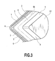
Fig. 3] Fig. 3 is an enlarged front view of a corner portion of the cutting insert shown inFig. 1 ; - [
Fig. 4] Fig. 4 is an enlarged view of a cross section (cross section taken on lines IV - IV) vertical to a cutting edge of the cutting insert shown inFig. 1 ; - [
Fig. 5A] Fig. 5A is an enlarged view of a cross section vertical to a cutting edge of a cutting insert according to a different embodiment of the present invention; and - [
Fig. 5B] Fig. 5B is an enlarged view of a cross section vertical to a cutting edge of a cutting insert according to a further different embodiment of the present invention. - Hereinafter, an explanation will be made of a cutting insert according to an embodiment of the present invention with reference to the drawings. The cutting insert is provided with an
insert body 1 formed in a substantially lozenge plate shape as shown inFig. 1 andFig. 2 . One of two opposing lozenge faces in theinsert body 1 is arake face 2 and the other is a seating face which is seated on a tool body of a cutting tool. Side faces extending between therake face 2 and the seating face areflanks 3. Each of the flanks is intersected generally at right angles to the two opposing lozenge faces and is a so-called negative type face having a flank angle of 0 degree. A side ridge portion of the lozenge face acting as therake face 2 is astraight cutting edge 5 formed in a substantially straight line. A ridge line of a corner portion having a sharp angle of the lozenge face is a nose 4 which is a cutting edge formed in a substantially arc shape. In the following explanation, the nose 4 and thestraight cutting edge 5 are called cuttingedges 4 and 5 as a whole. In the cutting insert, both of the opposing lozenge faces are selectively used as arake face 2, and thereby both of the lozenge faces can be used. The configuration of theinsert body 1 is not only the lozenge, but also may be changed into a substantial polygon such as a square, a rectangle, a parallelogram, a triangle or a hexagon, and a substantially round shape. At least thecutting edges 4 and 5, therake face 2, and theflanks 3 each are made of a hard alloy such as cemented carbide, coated cemented carbide, cermet and ceramic, or an ultra-high pressure sintered compact such as a diamond sintered compact and a cubic boron nitride sintered compact. - Boss faces 10 to be seated on a tool body (not shown) are respectively formed in the central portions of the two lozenge faces in the
insert body 1 opposing in the thickness direction thereof. The boss faces 10 each are a lozenge smaller than a lozenge face that forms a contour of theinsert body 1 and substantially flat. In addition, each of the boss faces 10 is formed in a slightly higher position in the thickness direction than thecutting edges 4 and 5. - A mount bore 1a formed of a substantially circular bore penetrating through the
insert body 1 in the thickness direction is formed in the center portion of the lozenge face. The cutting insert is removably fixed to an insert mount seat provided in the cutting tool body. The fixation of the cutting insert to the cutting tool body is made in such a manner that theboss face 10 is seated on a bottom face of the insert mount seat, at least one side face is made to be in contact with a wall face of the insert mount seat, and a lever or a pin as clamping means equipped in the cutting tool body is engaged to an inner peripheral face of the mount bore 1a of the insert. - The
rake face 2 adjacent to thecutting edges 4 and 5 is a curved face gradually inclined toward the center in the thickness direction of the insert (hereinafter, called downward, and the front face side is called upward) as it goes away from thecutting edges 4 and 5, or a combination of a substantially flat face and the curved face. In the present embodiment, the rake face adjacent to thestraight cutting edge 5 is flat and the rake face adjacent to the nose 4 is a conical curved surface. A rake angle, which is an inclination angle of therake face 2, is set to a positive value, for example, a range of more than 0° to 30° or less, and is set to 10° in the present embodiment. Not limited to this, therake face 2 may be an inclined surface inclined to project upward as it goes away from thecutting edges 4 and 5, or may be a flat plane extending horizontally. In addition, therake face 2 is not limited to the flat plane, but may be a curved surface to be formed in a convex shape toward either one of downward and upward directions. Alternatively thecutting edges 4 and 5 may be connected via a land (not shown) to therake face 2. The land is formed of a flat face along thecutting edges 4 and 5 and preferably has a width of approximately 0.02mm to 1.0mm in a direction vertical to thecutting edges 4 and 5. The land is selected from a negative land extending horizontally in a cross section vertical to thecutting edges 4 and 5, or a positive land formed of an inclined plane inclined downward as it goes away from thecutting edges 4 and 5. An inclined angle of the positive land is set to a range of, for example, more than 0° and 30° or less. - As viewed in a direction opposing the
rake face 2 as shown inFig. 1 , aconcave portion 6 extending along thecutting edges 4 and 5 is adjacent to an inner periphery of therake face 2 and has a circular shape including corner radius portions to make one round without disconnection. As shown inFig. 4 (cross section intersected at right angles to the cutting edges 4 and 5), theconcave portion 6 is connected to an end portion in an inside which is opposite to an end portion of therake face 2 connecting to thecutting edges 4 and 5, and is recessed downward of anextension surface 2a of therake face 2. Specifically, theconcave portion 6 includes a downwardinclined face 6b recessed downward from the end portion in the inside of therake face 2 described above and having a concave curved surface shape, and abottom face 6a extending substantially horizontally toward an inside (a direction toward the boss face 10) from a bottom end portion of the downwardinclined face 6b. Therefore, theconcave portion 6 is positioned lower than theextension surface 2a of therake face 2. An intersection line between thebottom face 6a of the concave portion and theextension surface 2a of therake face 2 is aninside end portion 6d of theconcave portion 6. Anintermediate face 8 formed of a horizontal flat plane extending from thebottom face 6a of the concave portion is present in the inside (a direction toward the boss face 10) of theinside end portion 6d of theconcave portion 6. The inside end portion of theintermediate face 8 is connected to a projectingwall face 9 to be described later. - The construction of the concave portion may be a concave groove shape as exemplified in
Fig. 5A and Fig. 5B instead of the one mentioned above. Specifically,concave portions inclined faces inclined faces concave portions - The
concave portions rake face 2 and formed in a circular shape to make one round without disconnection, but may be formed in a range corresponding to at least regions of thecutting edges 4 and 5 making contact with a workpiece material. For example, theconcave portions rake face 2 extending from the nose 4 or only in the inside of therake face 2 extending from the nose 4 and a part of thestraight cutting edge 5 adjacent to the nose 4 (not shown). Alternatively in a case where theconcave portions cutting edges 4 and 5, theconcave portions - In
Fig. 4 (cross section intersecting at right angles to the cutting edges 4 and 5), atop face 7a of theprojection 7 intersects theconcave portion 6 in a position closer to the center side in the thickness direction of the insert than the top end portion of the downwardinclined face 6b, extends toward the inward and downward of the insert from the intersection position, is gradually curved upward in a convex shape, and intersects thebottom face 6a of theconcave portion 6. Thetop face 7a of theprojection 7 is in a position equal to or higher than the downwardinclined face 6b and thebottom face 6a of the concave portion, and in a position equal to or lower than thevirtual extension surface 2a of therake face 2 not to project upward over theextension surface 2a. - In a case of drawing the
extension surface 2a of therake face 2 in a cross section vertical to thecutting edges 4 and 5 and in a case where therake face 2 is formed of a flat horizontal plane or an inclined plane, therake face 2 formed in a straight shape in the cross section may be extended as it is. On the other hand, in a case where therake face 2 is constructed of a curved surface to be in a convex shape toward any one of the downward and upward directions, a tangential line of therake face 2 at the inside end of therake face 2, that is, an intersection portion with the downwardinclined face 6b of theconcave portion 6, may be formed as a contour of theextension surface 2a. However, in a case where therake face 2 is constructed of a curved surface to be in a convex shape in the upward direction, the cutting chip has a stronger tendency to be away upward from therake face 2 as it flows out (moves away from the cutting edges 4 and 5). This tendency becomes even stronger as a curvature of the curve plane in the convex shape is larger. Therefore, in a case where the tangential line of therake face 2 in the intersection portion in a cross section vertical to thecutting edges 4 and 5 is inclined remarkably downward to a tangential line of therake face 2 at the position of thecutting edges 4 and 5, specifically in a case where an angle between both tangential lines is 15° or more, it is preferable that a straight line passing the intersection portion and thecutting edges 4 and 5 is defined as a contour of theextension surface 2a of the rake face in order to increase the possibility of contact of the cutting chip with the top face of the convex portion. - Further, a region of the
top face 7a of theprojection 7 which is closer to the outside end portion than the intermediate portion of thetop face 7a, that is, a region in the side of thecutting edges 4 and 5, is formed of a convex curved surface which gradually inclines nearer to an inclination of theextension surface 2a as it goes toward the inward and upward sides, and on the other hand, a region thereof which is closer to the inside end portion than the intermediate portion is formed in a convex curved surface to be gradually away from theextension surface 2a as it goes toward the inward side. In other words, at least a part of thetop face 7a of theprojection 7, particularly a region thereof downstream of a contact point between the cutting chip and theprojection 7, is away from theextension surface 2a of therake face 2 as it goes away from thecutting edges 4 and 5. - In addition, the
top face 7a of theprojection 7 is formed of a curved surface forming a convex curve toward the upward side as viewed in a cross section abreast of the cutting edge 4 which is the nose, and in a cross section in parallel with thestraight cutting edge 5. Not limited to this, thetop face 7a of theprojection 7 may be shaped to project upward in a cross section in parallel with thecutting edges 4 and 5, and, for example, may be possibly changed into a substantially reverse V-letter shape, a substantially isosceles trapezoid, and a substantially reverse W-letter shape with two top portions. - As shown in
Fig. 1 andFig. 3 , theprojection 7 extends to be longer in a direction vertical to thecutting edges 4 and 5 as viewed in a direction opposing therake face 2, and is a substantially elliptical body having a long axis in a direction vertical to thecutting edges 4 and 5 and a short axis in a direction in parallel with thecutting edges 4 and 5. The configuration of theprojection 7 is not limited to the substantially elliptical body, and may be possibly changed into a substantially spherical shape, a substantially triangular pyramid, and a substantially quadrangular pyramid a bottom face of which is a rectangle, a trapezoid, a parallelogram or the like. Further, a plurality of theprojections 7 are arranged in parallel by equal intervals over an entire length of an extending direction of theconcave portion 6 including the nose 4 along thecutting edges 4 and 5. - In addition, the projecting
wall face 9 is formed inside of the concave portion 6 (backward of theconcave portion 6 as viewed from the cutting edges 4 and 5) as viewed in a cross section vertical to thecutting edges 4 and 5. The projectingwall face 9 gradually projects upward as it goes away from thecutting edges 4 and 5. In the present embodiment, the projectingwall face 9 is connected to the inside end portion of theintermediate face 8 provided inside of thebottom face 6a of the concave portion, and forms an inclined plane projecting gradually upward as it goes inward from the inside end portion. The projectingwall face 9 is not limited to a flat inclined surface having a constant inclination, but may be constructed of a curved surface to be in a convex shape or in a concave shape toward the upward side and thecutting edges 4 and 5. Theconcave portion 6 and the projectingwall face 9 may be directly connected or may be connected via theintermediate face 8 formed of the flat plane or the curved surface. In a case where theintermediate face 8 is provided, theintermediate face 8 is preferably provided in a position equal to or lower than the projectingwall face 9 for appropriately forcing the cutting chip to collide with the projectingwall face 9 without interruption of the outflow of the cutting chip. The inside end portion of the projectingwall face 9 is connected to theboss face 10 formed in the center of theinsert body 1. It should be noted that the projectingwall face 9 may be omitted. - The cutting insert explained as above is seated at one lozenge face on the bottom face of the insert mount seat provided in the cutting tool body. In addition, at least one of the side faces connected to the
straight cutting edge 5 which is not involved in cutting is in contact with the wall face of the insert mount seat, and the cutting insert is fixed by a lever or a pin as clamping means equipped in the cutting tool body. Another lozenge face is used as therake face 2. - The cutting insert is given a feed, for example, in a direction parallel with a rotation central line of a workpiece material to cut an outer periphery of the workpiece material. In this case, the lateral cutting edge and a part of the nose 4 adjacent to the lateral cutting edge make contact with the workpiece material over entire cutting in a direction vertical to the rotation central line for cutting primarily. A portion of the nose 4 as a front cutting edge is a portion forming a work face of the workpiece material and is in slight contact with the workpiece material or slightly cuts the workpiece material.
- In the cutting insert as explained above, chips generated by the
straight cutting edge 5 as the lateral cutting edge and a part of the nose 4 adjacent to thecutting edge 5 flow on therake face 2 toward theconcave portion 6, and go away from therake face 2 in the intersection portion between therake face 2 and theconcave portion 6 to flow into theconcave portion 6. The chips flown into theconcave portion 6 make contact with a part of thetop face 7a of theprojection 7 projecting upward from thebottom face 6a of the concave portion. The flow of chips having contacted a part of thetop face 7a of theprojection 7 is restricted by thetop face 7a to keep the outflow direction to be in a constant direction. - In a cross section in a direction vertical to the
cutting edges 4 and 5, thetop face 7a of theprojection 7 extends inward and downward from the outside end portion intersecting with theconcave portion 6 at a position slightly lower than the top end portion of the downwardinclined face 6b of theconcave portion 6, is gradually curved upward in a convex shape, and reaches the inside end portion intersecting with thebottom face 6a of theconcave portion 6. Thetop face 7a of theprojection 7 is at a position higher than the downwardinclined face 6b and thebottom face 6a of theconcave portion 6, and in a position equal to or lower than theextension surface 2a of therake face 2, and does not project upward over theextension surface 2a. In addition, at least a part of thetop face 7a of theprojection 7, particularly a region thereof downstream of the contact point between the chip and theprojection 7 is away from the extension surface of the rake face as it goes away from the cutting edges. Therefore, after a chip passes therake face 2, it goes down from theextension surface 2a of therake face 2 and gradually approaches and makes contact with thetop face 7a of theproj ection 7. As a result, compared to the conventional cutting insert, an impact generated upon collision of the chip can be suppressed to suppress the deformation resistance of the chip. In addition, abrasion of theprojection 7 can be suppressed to maintain the function of keeping the outflow direction of the chip to be in a constant direction for a long period of time. These functions are remarkably effective for deep cutting in which the deformation resistance of the chip has a tendency of increasing. In addition, since heat generation is suppressed by suppressing the friction in theprojection 7, these functions are effective for materials such heat resistant alloy and ultra-heat resistant alloy in which the heat generation is remarkable at cutting, and for materials having a high strength at a high temperature. - A region of the
top face 7a of the projection closer to the outside end portion than the intermediate portion thereof is formed in a convex curved surface, and is constructed in such a manner as to be gradually approaching theextension surface 2a of therake face 2 as it is away from thecutting edges 4 and 5 to go inward. Therefore, since the outflow direction of the chip passing therake face 2 and the tangential direction of the curved surface as thetop face 7a of the projection are nearly in parallel with each other, thetop face 7a of the projection makes gradual contact with the chip. Therefore, remarkable deformation of the cutting chip can be suppressed. On the other hand, a region of theprojection 7 in the side of the inside end portion is formed in a convex curve and is constructed such that, at least a region thereof downstream of the a contact point between the cutting chip and theprojection 7 is gradually away from theextension surface 2a of therake face 2 as it is away from thecutting edges 4 and 5 to go inward, and an inclination of the surface tangential line is larger than that of theextension surface 2a. In consequence, since the chip is quickly away from thetop face 7a of theprojection 7, the remarkable deformation of the cutting chip can be suppressed. As a result of these factors, the vibration and chatter due to the deformation resistance of the chip can be suppressed. - Further, the
projection 7 in the present embodiment is formed to be smaller than conventional. Because a main object of theprojection 7 is not to forcibly break the chip as conventional, but to suppress collision between the chip and theprojection 7 to suppress the deformation resistance of the chip. Therefore, it is possible to arrange at least one of the projections in the vicinity of the nose as shown inFig. 3 where it is difficult to arrange the projection because of lack of a formation space in the conventional construction. Theprojection 7 can arrange its longitudinal axis on a bisector of the nose 4. - As described above, the chip is deformed in a convex shape along the
top face 7a of theprojection 7 in a cross section abreast of thecutting edges 4 and 5 which is a width direction. Here, since thetop face 7a of theprojection 7 is formed in a curved surface having a convex curve shape in the cross section, a contact range between thetop face 7a of theprojection 7 and the chip is limited to be small. Therefore, the contact between the chip and thetop face 7a of the projection is reduced to further suppress the deformation resistance of the chip. The function of suppressing the deformation resistance of the cutting chip is further strengthened along with the function based upon the convex curve shape of thetop face 7a of theprojection 7 in a cross section in a direction vertical to thecutting edges 4 and 5 as described above. - Further, since the
projection 7 formed in theconcave portion 6 results in reinforcing theconcave portion 6, a strength reduction of thecutting edges 4 and 5 due to theconcave portion 6 can be prevented. Therefore, damages such as chipping or breaking of thecutting edges 4 and 5 can be prevented to prevent a reduction in cutting edge lifetime. - In addition, as described before, the
concave portion 6 extending along thecutting edges 4 and 5 is formed in a circular shape to be adjacent to the inner periphery of therake face 2 and make one round without disconnection. Further, a plurality of the projections provided in theconcave portion 6 each are formed in a substantially elliptical shape having a longitudinal axis in a direction vertical to thecutting edges 4 and 5, and are arranged to be in parallel by equal intervals over an entire length of theconcave portion 6 in the extending direction along thecutting edges 4 and 5. Therefore, the function of keeping the outflow direction of the chip to be in a constant direction, the function of suppressing the deformation resistance of the chip, and the function of preventing a reduction in cutting edge lifetime as described above, can be obtained in an entire region of thecutting edges 4 and 5. Therefore, a desired effect can be obtained regardless of a size of cut. - In addition, the
rake face 2 extending from thecutting edges 4 and 5 is a flat inclined surface gradually inclined toward the center of the insert in the thickness direction as it goes away from thecutting edges 4 and 5, and is set to 10° as the inclined angle to a horizontal plane in parallel with the seat plane. In consequence, since the cutting performance of thecutting edges 4 and 5 is improved, the thickness of the chip gets thin and the flow of the chip on therake face 2 can be promoted. Therefore, the inflow of the chip into theconcave portion 6 and the contact of the chip with thetop face 7a of theprojection 7 are promoted to securely keep the flow direction to be in a constant direction. Further, by making the thickness of the chip be thin, the deformation resistance of the chip at the time of being deformed in a convex curve shape along thetop face 7a of the projection is suppressed. - As viewed in a direction opposing the
rake face 2, theprojection 7 extends as the longitudinal axis in a direction substantially vertical to thecutting edges 4 and 5, and is formed such that a length of theprojection 7 in a direction intersecting with, or at right angles to, thecutting edges 4 and 5 is larger than a width abreast of or in a direction in parallel with thecutting edges 4 and 5. That is, theprojection 7 is formed to be longer in a direction along the outflow direction of the chip. Thereby since flow of the chip is restricted by thetop face 7a of theprojection 7, the function of keeping the outflow direction to be in a constant direction is further strengthened. On the other hand, since a width of theprojection 7 in a direction abreast of thecutting edges 4 and 5 is small, the deformation resistance of the chip is suppressed. Further, since theprojection 7 functions as a rib reinforcing theconcave portion 6, a reduction in cutting edge strength due to a provision of theconcave portion 6 can be effectively prevented. Accordingly damages such as chipping or breaking of thecutting edges 4 and 5 can be prevented to securely prevent a reduction in the cutting edge lifetime. - The projecting
wall face 9 projects upward over therake face 2 in a position backward of theconcave portion 6 as viewed from thecutting edges 4 and 5. The chip, the outflow direction of which is kept to be in a constant direction by theprojection 7, collides with a constant position of the projectingwall face 9 to stabilize deformation due to the collision. Therefore, the stable cutting chip processing can be obtained. - As explained above, since the cutting insert according to the present embodiment can suppress the deformation resistance of the chip by a novel construction regarding the concave portion and the projection, the vibration or chatter of the cutting insert or the cutting tool using it can be suppressed.
- The present invention is not limited to the cutting insert explained above, and needless to say, additions, changes and elimination of appropriate constructions are possible within the scope without departing from the concept of the present invention. In addition, the present embodiment explains the cutting insert for cutting the outer periphery of the workpiece material, but the present invention can be applied to a cutting insert for cutting the inner periphery and the end face of the workpiece material. In addition, the present invention can be applied to a cutting insert used for cutting off/groove work. Other than that, the present invention can be applied to a cutting insert used for milling and drilling. Also in regard to the aspect of the cutting insert, the present invention can be applied not only to a negative insert but also to a positive insert. Also in regard to the configuration of the
cutting edges 4 and 5, at least a part of thecutting edges 4 and 5 may be inclined to gradually go down in the thickness direction as it goes from one end portion to the other end portion. Alternatively thecutting edges 4 and 5 each may be formed in a curved shape to curve in the thickness direction of theinsert body 1.
Claims (7)
- A cutting insert comprising:at least one cutting edge;a rake face extending from the cutting edge;a concave portion positioned adjacent to and backward of the rake face as viewed from the cutting edge; and
at least one projection projecting from a bottom face of the concave portion, whereinan entirety of the projection is positioned closer to the bottom face of the concave portion than a surface formed by extending the rake face toward the concave portion,at least a part of a top face of the projection is away from an extension surface of the rake face as it goes away from the cutting edge. - A cutting insert according to claim 1, wherein
the concave portion extends abreast of the cutting edge and a plurality of the projections are positioned over a substantially entire length of the concave portion along an extending direction of the concave portion. - A cutting insert according to claim 1 or 2, wherein
a part of the projection from an end portion in the insert outside direction to an intermediate portion thereof in a cross section intersecting with the cutting edge approaches the extension surface of the rake face as it goes away from the cutting edge - A cutting insert according to any of claim 1 to 3, wherein
in a cross section abreast of the cutting edge, the projection has the top face forming a convex curve toward an upward side. - A cutting insert according to any of claim 1 to 4, wherein
as viewed in a direction opposing the rake face, a length of the projection in a direction intersecting with the cutting edge is larger than a width of the projection in a direction abreast of the cutting edge. - A cutting insert according to any of claim 1 to 5, wherein
the cutting insert is provided with a projecting wall face projecting upward over a top portion of the projection at the backward of the concave portion as viewed from the cutting edge. - A cutting insert according to any of claim 1 to 6, wherein
the at least one projection is formed in a portion of the concave portion adjacent to a nose.
Applications Claiming Priority (2)
| Application Number | Priority Date | Filing Date | Title |
|---|---|---|---|
| JP2009149597 | 2009-06-24 | ||
| PCT/JP2010/060286 WO2010150696A1 (en) | 2009-06-24 | 2010-06-17 | Cutting insert |
Publications (2)
| Publication Number | Publication Date |
|---|---|
| EP2446990A1 true EP2446990A1 (en) | 2012-05-02 |
| EP2446990A4 EP2446990A4 (en) | 2013-07-31 |
Family
ID=43386466
Family Applications (1)
| Application Number | Title | Priority Date | Filing Date |
|---|---|---|---|
| EP10792014.2A Withdrawn EP2446990A4 (en) | 2009-06-24 | 2010-06-17 | Cutting insert |
Country Status (9)
| Country | Link |
|---|---|
| US (1) | US20120087751A1 (en) |
| EP (1) | EP2446990A4 (en) |
| JP (1) | JPWO2010150696A1 (en) |
| KR (1) | KR20120023122A (en) |
| CN (1) | CN102458736A (en) |
| BR (1) | BRPI1013526A2 (en) |
| CA (1) | CA2766773A1 (en) |
| RU (1) | RU2492970C1 (en) |
| WO (1) | WO2010150696A1 (en) |
Cited By (3)
| Publication number | Priority date | Publication date | Assignee | Title |
|---|---|---|---|---|
| EP2636472A4 (en) * | 2010-11-04 | 2014-08-27 | Kyocera Corp | CUTTING PART, CUTTING TOOL, AND METHOD FOR MANUFACTURING CUTTING PRODUCT USING THE SAME |
| WO2015081353A1 (en) * | 2013-12-02 | 2015-06-11 | Ceratizit Austria Gesellschaft M.B.H. | Rotary machining cutting insert |
| EP3539696A1 (en) * | 2018-03-13 | 2019-09-18 | AB Sandvik Coromant | Turning tool for metal cutting comprising a coolant channel |
Families Citing this family (26)
| Publication number | Priority date | Publication date | Assignee | Title |
|---|---|---|---|---|
| BRPI0721368A2 (en) * | 2007-02-16 | 2013-01-15 | Taegutec Ltd. | double side cutting insert and cutter mounting the same |
| JP5081229B2 (en) * | 2007-03-27 | 2012-11-28 | 京セラ株式会社 | Cutting insert, cutting tool, and work material cutting method using the same |
| JP5895456B2 (en) * | 2010-11-15 | 2016-03-30 | 三菱マテリアル株式会社 | Cutting insert |
| US8967920B2 (en) * | 2011-09-13 | 2015-03-03 | Iscar, Ltd. | Cutting insert and chip-control arrangement therefor |
| DE102011082979A1 (en) * | 2011-09-19 | 2013-03-21 | Komet Group Gmbh | Reaming tool and method for its production |
| US9656335B2 (en) * | 2013-03-08 | 2017-05-23 | United Technologies Corporation | Broach tool rake face with a tailored surface topography |
| DE102014102173B4 (en) | 2013-03-22 | 2021-06-10 | Kennametal India Limited | CUTTING INSERT WITH A LINEAR AND A CONCAVE CUTTING EDGE SECTION AND A DRILLING TOOL |
| US9724761B2 (en) | 2013-03-22 | 2017-08-08 | Kennametal India Limited | Cutting insert with a linear and a concave cutting edge portion |
| RU2555295C1 (en) * | 2014-01-09 | 2015-07-10 | Общество с ограниченной ответственностью "Сборные конструкции инструмента, фрезы Москвитина" | Insert and face cutter |
| RU2562195C1 (en) * | 2014-03-04 | 2015-09-10 | Общество с ограниченной ответственнстью "Сборные конструкции инструмента, фрезы Москвитина" | Cutter (versions) |
| CN103862074B (en) * | 2014-04-08 | 2016-02-10 | 哈尔滨理工大学 | A kind of double break bits structure heavy cutting blade |
| US9731354B2 (en) * | 2014-05-07 | 2017-08-15 | Kennametal Inc. | Cutting insert with micro-channels |
| WO2016035490A1 (en) * | 2014-09-05 | 2016-03-10 | 住友電工ハードメタル株式会社 | Throwaway tip |
| US10195673B2 (en) * | 2015-12-11 | 2019-02-05 | Kennametal Inc. | Ceramic cutting insert and method of making same |
| RU2645531C1 (en) * | 2017-06-09 | 2018-02-21 | Общество с ограниченной ответственностью "Сборные конструкции инструмента, фрезы Москвитина" | Mill for heavy feed and a cutting plate for it |
| RU178490U1 (en) * | 2017-12-27 | 2018-04-05 | Общество с ограниченной ответственностью "Вириал" | REPLACEABLE MULTI-DIMENSIONAL CUTTING PLATE |
| US20200001374A1 (en) * | 2018-06-29 | 2020-01-02 | Herramientas Preziss, S.L. | Cutting Insert Applicable To Machining Tools And The Tool Bearing It |
| DE102018133164A1 (en) * | 2018-12-20 | 2020-06-25 | Zcc Cutting Tools Europe Gmbh | Cutting tool |
| EP3738698B1 (en) * | 2019-05-16 | 2022-11-02 | AB Sandvik Coromant | Turning insert for metal cutting, a cutting tool and a method to machine a metal workpiece |
| JP7374726B2 (en) * | 2019-11-14 | 2023-11-07 | 株式会社アイシン福井 | Cutting tools |
| JP7372116B2 (en) * | 2019-11-14 | 2023-10-31 | 株式会社アイシン福井 | Cutting tools |
| US11413689B2 (en) * | 2020-05-28 | 2022-08-16 | Kennametal Inc. | Cutting inserts with control cavities |
| CN117120190A (en) * | 2021-02-24 | 2023-11-24 | 株式会社爱信福井 | cutting tools |
| WO2022180697A1 (en) * | 2021-02-24 | 2022-09-01 | アイシン・エイ・ダブリュ工業株式会社 | Cutting tool |
| JP6923855B1 (en) * | 2021-02-26 | 2021-08-25 | 株式会社タンガロイ | Cutting insert |
| JP7094501B1 (en) | 2021-11-30 | 2022-07-04 | 株式会社タンガロイ | Cutting tools |
Family Cites Families (26)
| Publication number | Priority date | Publication date | Assignee | Title |
|---|---|---|---|---|
| SE354593C (en) * | 1972-05-17 | 1975-01-20 | Sandvik Ab | |
| CA1194684A (en) * | 1981-01-30 | 1985-10-08 | Kennametal Inc. | Cutting insert |
| JPH067845Y2 (en) * | 1984-10-26 | 1994-03-02 | 東芝タンガロイ株式会社 | Throw-away tip |
| JPS61151806U (en) * | 1985-03-13 | 1986-09-19 | ||
| DE8700393U1 (en) * | 1987-01-09 | 1988-05-05 | Nederlandse Hardmetaal Fabrieken B.V., Arnhem | Cutting tool for metal cutting |
| SU1590202A1 (en) * | 1988-03-18 | 1990-09-07 | Всесоюзный заочный машиностроительный институт | Round cutting bit |
| JPH0253305U (en) * | 1988-10-11 | 1990-04-17 | ||
| SU1611583A1 (en) * | 1988-10-25 | 1990-12-07 | Ленинградский Филиал Специального Производственно-Технологического Бюро "Оргпримтвердосплав" | Polyhedral cutting bit |
| JP2537101Y2 (en) * | 1991-03-29 | 1997-05-28 | 三菱マテリアル株式会社 | Indexable tip |
| EP0506078B1 (en) * | 1991-03-29 | 1996-12-11 | Mitsubishi Materials Corporation | Indexable cutter insert |
| US5203649A (en) * | 1991-10-07 | 1993-04-20 | Gte Valentine Corporation | High productivity, high metal removal rate insert |
| JP2553321Y2 (en) * | 1992-04-27 | 1997-11-05 | 住友電気工業株式会社 | Indexable tip |
| SE502084C2 (en) * | 1993-04-05 | 1995-08-07 | Sandvik Ab | Cutting plate with concave curved chip breakers |
| DE4402759A1 (en) * | 1994-01-31 | 1995-08-03 | Widia Heinlein Gmbh | Cutting insert |
| IL113122A0 (en) * | 1995-03-24 | 1995-06-29 | Iscar Ltd | A cutting insert |
| JP3750305B2 (en) * | 1997-09-09 | 2006-03-01 | 株式会社タンガロイ | Throwaway tip |
| JP3487195B2 (en) * | 1998-10-19 | 2004-01-13 | 三菱マテリアル株式会社 | Large indexable inserts |
| JP2002254214A (en) * | 2001-02-27 | 2002-09-10 | Mitsubishi Materials Corp | Indexable tip |
| JP3812473B2 (en) * | 2001-11-20 | 2006-08-23 | 三菱マテリアル株式会社 | Throwaway tip |
| RU30297U1 (en) * | 2002-12-10 | 2003-06-27 | Закрытое акционерное общество "Дальневосточная технология" | Tungsten Carbide Plate |
| CN2902531Y (en) * | 2006-03-03 | 2007-05-23 | 自贡硬质合金有限责任公司 | Turning cutter for roughing cut |
| WO2008053633A1 (en) * | 2006-10-31 | 2008-05-08 | Kyocera Corporation | Cutting insert |
| JP4999575B2 (en) * | 2007-06-27 | 2012-08-15 | 京セラ株式会社 | Cutting tools |
| JP5092865B2 (en) * | 2008-04-17 | 2012-12-05 | 株式会社タンガロイ | Throwaway tip |
| CN201220282Y (en) * | 2008-07-22 | 2009-04-15 | 大连大学 | Knife tool chip breaker |
| JP5515504B2 (en) * | 2008-08-22 | 2014-06-11 | 三菱マテリアル株式会社 | Cutting insert |
-
2010
- 2010-06-17 EP EP10792014.2A patent/EP2446990A4/en not_active Withdrawn
- 2010-06-17 BR BRPI1013526A patent/BRPI1013526A2/en not_active IP Right Cessation
- 2010-06-17 JP JP2011519835A patent/JPWO2010150696A1/en active Pending
- 2010-06-17 CN CN2010800282826A patent/CN102458736A/en active Pending
- 2010-06-17 KR KR1020117030703A patent/KR20120023122A/en not_active Ceased
- 2010-06-17 WO PCT/JP2010/060286 patent/WO2010150696A1/en not_active Ceased
- 2010-06-17 RU RU2012102267/02A patent/RU2492970C1/en not_active IP Right Cessation
- 2010-06-17 CA CA2766773A patent/CA2766773A1/en not_active Abandoned
-
2011
- 2011-12-21 US US13/333,522 patent/US20120087751A1/en not_active Abandoned
Cited By (6)
| Publication number | Priority date | Publication date | Assignee | Title |
|---|---|---|---|---|
| EP2636472A4 (en) * | 2010-11-04 | 2014-08-27 | Kyocera Corp | CUTTING PART, CUTTING TOOL, AND METHOD FOR MANUFACTURING CUTTING PRODUCT USING THE SAME |
| US9278393B2 (en) | 2010-11-04 | 2016-03-08 | Kyocera Corporation | Cutting insert, cutting tool, and method of manufacturing machined product using the same |
| WO2015081353A1 (en) * | 2013-12-02 | 2015-06-11 | Ceratizit Austria Gesellschaft M.B.H. | Rotary machining cutting insert |
| EP3539696A1 (en) * | 2018-03-13 | 2019-09-18 | AB Sandvik Coromant | Turning tool for metal cutting comprising a coolant channel |
| WO2019174921A1 (en) * | 2018-03-13 | 2019-09-19 | Ab Sandvik Coromant | Turning tool for metal cutting comprising a coolant channel |
| US11590580B2 (en) | 2018-03-13 | 2023-02-28 | Ab Sandvik Coromant | Turning tool for metal cutting comprising a coolant channel |
Also Published As
| Publication number | Publication date |
|---|---|
| RU2012102267A (en) | 2013-07-27 |
| EP2446990A4 (en) | 2013-07-31 |
| KR20120023122A (en) | 2012-03-12 |
| WO2010150696A1 (en) | 2010-12-29 |
| CA2766773A1 (en) | 2010-12-29 |
| CN102458736A (en) | 2012-05-16 |
| BRPI1013526A2 (en) | 2016-04-05 |
| US20120087751A1 (en) | 2012-04-12 |
| RU2492970C1 (en) | 2013-09-20 |
| JPWO2010150696A1 (en) | 2012-12-10 |
Similar Documents
| Publication | Publication Date | Title |
|---|---|---|
| EP2446990A1 (en) | Cutting insert | |
| US8545136B2 (en) | Cutting insert | |
| JP5187447B2 (en) | Cutting inserts and cutting tools | |
| JP5092865B2 (en) | Throwaway tip | |
| JP5515504B2 (en) | Cutting insert | |
| CN101626860B (en) | Inserts for Thread Cutting | |
| EP3088111B1 (en) | Drill insert and indexable drill | |
| JP7248892B2 (en) | Cutting inserts, indexable ball end mills, and end mill bodies for indexable ball end mills | |
| JP4729894B2 (en) | Insert and throw-away cutting tools | |
| JP6361948B2 (en) | Cutting inserts and cutting tools | |
| JP2008200831A (en) | Cutting insert | |
| JP7417137B2 (en) | Cutting inserts and indexable ball end mills | |
| JPWO2019082843A1 (en) | Cutting insert and replaceable ball end mill | |
| JP2007290057A (en) | Ultra-high pressure sintered body cutting tool |
Legal Events
| Date | Code | Title | Description |
|---|---|---|---|
| PUAI | Public reference made under article 153(3) epc to a published international application that has entered the european phase |
Free format text: ORIGINAL CODE: 0009012 |
|
| 17P | Request for examination filed |
Effective date: 20120119 |
|
| AK | Designated contracting states |
Kind code of ref document: A1 Designated state(s): AL AT BE BG CH CY CZ DE DK EE ES FI FR GB GR HR HU IE IS IT LI LT LU LV MC MK MT NL NO PL PT RO SE SI SK SM TR |
|
| DAX | Request for extension of the european patent (deleted) | ||
| A4 | Supplementary search report drawn up and despatched |
Effective date: 20130701 |
|
| RIC1 | Information provided on ipc code assigned before grant |
Ipc: B23B 27/22 20060101AFI20130625BHEP |
|
| STAA | Information on the status of an ep patent application or granted ep patent |
Free format text: STATUS: THE APPLICATION IS DEEMED TO BE WITHDRAWN |
|
| 18D | Application deemed to be withdrawn |
Effective date: 20140129 |