EP2446196B1 - Method for providing heat - Google Patents
Method for providing heat Download PDFInfo
- Publication number
- EP2446196B1 EP2446196B1 EP10723609.3A EP10723609A EP2446196B1 EP 2446196 B1 EP2446196 B1 EP 2446196B1 EP 10723609 A EP10723609 A EP 10723609A EP 2446196 B1 EP2446196 B1 EP 2446196B1
- Authority
- EP
- European Patent Office
- Prior art keywords
- storage reservoir
- solar collector
- carrier medium
- thermal carrier
- heating
- Prior art date
- Legal status (The legal status is an assumption and is not a legal conclusion. Google has not performed a legal analysis and makes no representation as to the accuracy of the status listed.)
- Not-in-force
Links
- 238000000034 method Methods 0.000 title claims description 13
- 238000010438 heat treatment Methods 0.000 claims description 27
- 238000013517 stratification Methods 0.000 claims description 10
- 230000005855 radiation Effects 0.000 claims description 5
- 239000008235 industrial water Substances 0.000 claims 3
- 238000012546 transfer Methods 0.000 description 35
- XLYOFNOQVPJJNP-UHFFFAOYSA-N water Substances O XLYOFNOQVPJJNP-UHFFFAOYSA-N 0.000 description 6
- 239000007789 gas Substances 0.000 description 4
- IJGRMHOSHXDMSA-UHFFFAOYSA-N Atomic nitrogen Chemical compound N#N IJGRMHOSHXDMSA-UHFFFAOYSA-N 0.000 description 2
- 230000002528 anti-freeze Effects 0.000 description 2
- QVGXLLKOCUKJST-UHFFFAOYSA-N atomic oxygen Chemical compound [O] QVGXLLKOCUKJST-UHFFFAOYSA-N 0.000 description 2
- 230000008014 freezing Effects 0.000 description 2
- 238000007710 freezing Methods 0.000 description 2
- 239000007788 liquid Substances 0.000 description 2
- 238000013021 overheating Methods 0.000 description 2
- 239000001301 oxygen Substances 0.000 description 2
- 229910052760 oxygen Inorganic materials 0.000 description 2
- 238000010521 absorption reaction Methods 0.000 description 1
- 238000009835 boiling Methods 0.000 description 1
- 238000010276 construction Methods 0.000 description 1
- 238000005260 corrosion Methods 0.000 description 1
- 230000007797 corrosion Effects 0.000 description 1
- 238000013461 design Methods 0.000 description 1
- 238000001704 evaporation Methods 0.000 description 1
- 230000008020 evaporation Effects 0.000 description 1
- 238000009434 installation Methods 0.000 description 1
- 239000012528 membrane Substances 0.000 description 1
- 229910052757 nitrogen Inorganic materials 0.000 description 1
- 238000002360 preparation method Methods 0.000 description 1
- 238000010992 reflux Methods 0.000 description 1
- 238000000926 separation method Methods 0.000 description 1
- 238000009834 vaporization Methods 0.000 description 1
- 230000008016 vaporization Effects 0.000 description 1
- 238000009423 ventilation Methods 0.000 description 1
Images
Classifications
-
- F—MECHANICAL ENGINEERING; LIGHTING; HEATING; WEAPONS; BLASTING
- F24—HEATING; RANGES; VENTILATING
- F24D—DOMESTIC- OR SPACE-HEATING SYSTEMS, e.g. CENTRAL HEATING SYSTEMS; DOMESTIC HOT-WATER SUPPLY SYSTEMS; ELEMENTS OR COMPONENTS THEREFOR
- F24D11/00—Central heating systems using heat accumulated in storage masses
- F24D11/002—Central heating systems using heat accumulated in storage masses water heating system
- F24D11/003—Central heating systems using heat accumulated in storage masses water heating system combined with solar energy
-
- F—MECHANICAL ENGINEERING; LIGHTING; HEATING; WEAPONS; BLASTING
- F24—HEATING; RANGES; VENTILATING
- F24D—DOMESTIC- OR SPACE-HEATING SYSTEMS, e.g. CENTRAL HEATING SYSTEMS; DOMESTIC HOT-WATER SUPPLY SYSTEMS; ELEMENTS OR COMPONENTS THEREFOR
- F24D19/00—Details
- F24D19/0095—Devices for preventing damage by freezing
-
- F—MECHANICAL ENGINEERING; LIGHTING; HEATING; WEAPONS; BLASTING
- F24—HEATING; RANGES; VENTILATING
- F24D—DOMESTIC- OR SPACE-HEATING SYSTEMS, e.g. CENTRAL HEATING SYSTEMS; DOMESTIC HOT-WATER SUPPLY SYSTEMS; ELEMENTS OR COMPONENTS THEREFOR
- F24D3/00—Hot-water central heating systems
- F24D3/04—Hot-water central heating systems with the water under high pressure
-
- F—MECHANICAL ENGINEERING; LIGHTING; HEATING; WEAPONS; BLASTING
- F24—HEATING; RANGES; VENTILATING
- F24D—DOMESTIC- OR SPACE-HEATING SYSTEMS, e.g. CENTRAL HEATING SYSTEMS; DOMESTIC HOT-WATER SUPPLY SYSTEMS; ELEMENTS OR COMPONENTS THEREFOR
- F24D3/00—Hot-water central heating systems
- F24D3/10—Feed-line arrangements, e.g. providing for heat-accumulator tanks, expansion tanks ; Hydraulic components of a central heating system
- F24D3/1008—Feed-line arrangements, e.g. providing for heat-accumulator tanks, expansion tanks ; Hydraulic components of a central heating system expansion tanks
-
- F—MECHANICAL ENGINEERING; LIGHTING; HEATING; WEAPONS; BLASTING
- F24—HEATING; RANGES; VENTILATING
- F24D—DOMESTIC- OR SPACE-HEATING SYSTEMS, e.g. CENTRAL HEATING SYSTEMS; DOMESTIC HOT-WATER SUPPLY SYSTEMS; ELEMENTS OR COMPONENTS THEREFOR
- F24D2200/00—Heat sources or energy sources
- F24D2200/14—Solar energy
-
- Y—GENERAL TAGGING OF NEW TECHNOLOGICAL DEVELOPMENTS; GENERAL TAGGING OF CROSS-SECTIONAL TECHNOLOGIES SPANNING OVER SEVERAL SECTIONS OF THE IPC; TECHNICAL SUBJECTS COVERED BY FORMER USPC CROSS-REFERENCE ART COLLECTIONS [XRACs] AND DIGESTS
- Y02—TECHNOLOGIES OR APPLICATIONS FOR MITIGATION OR ADAPTATION AGAINST CLIMATE CHANGE
- Y02B—CLIMATE CHANGE MITIGATION TECHNOLOGIES RELATED TO BUILDINGS, e.g. HOUSING, HOUSE APPLIANCES OR RELATED END-USER APPLICATIONS
- Y02B10/00—Integration of renewable energy sources in buildings
- Y02B10/20—Solar thermal
Definitions
- the invention relates to a method according to the preamble of claim 1.
- a method in which the solar collector is filled with solar radiation with a heat transfer medium and flows through to to heat the heat transfer medium, and in which the solar collector is otherwise emptied, wherein the heat transfer medium is collected in a storage container, and wherein the heat transfer medium in the storage tank and in the solar collector is kept under increased pressure.
- the disadvantage of the given solution is that for the use of heat in a building heating at least one heat exchanger is required, and that it can come to evaporate at high solar radiation and low consumption losses of heat transfer medium. In addition, the absorption of oxygen from the air can cause corrosion.
- Object of the present invention is to avoid these disadvantages and to provide a solution that is simple, inexpensive, robust and efficient to equal. Robust not only means insensitivity in the mechanical sense, but also an unproblematic control behavior. Efficient means mainly a high efficiency and a good utilization of the heat supply.
- the storage container is partially filled with heat transfer medium and partially with gas in all operating conditions that the heat transfer medium is removed directly for heating a building from the storage container.
- service water can be heated.
- Essential to the present invention is the fact that the overall system is always kept under pressure, whereby several goals are achieved simultaneously.
- the heat transfer medium under pressure can be used directly for heating the building, so that any heat exchanger in the heating system can be avoided.
- a heat exchanger means a temperature loss of about 3 K to 5 K, resulting in a corresponding loss of efficiency.
- the heat transfer medium consists mainly of water, which boils under normal pressure at 100 ° C. Temperatures of 120 ° C to 140 ° C can certainly be allowed with the solution according to the invention. As a result of the closed system, there is no loss of heat transfer medium.
- a particularly simple construction is achieved if the heat transfer medium in the storage container has a free surface. Membranes or the like are not required for the separation of air and heat transfer medium.
- a plurality of solar collectors and / or storage containers can be connected in parallel. In this way, it is not only possible to increase the overall performance, but also to take into account an east-west orientation of the solar collectors, if this is necessary due to structural conditions.
- service water is heated by being passed through a heat exchanger in the storage tank.
- a solar system can be displayed with simple means, which serves both for heating and for hot water.
- a spiral tube heat exchanger which stretches in the vertical direction over a substantial part of the storage container, the temperature stratification of the heat transfer medium in the storage container can be optimally utilized.
- air is used as the gas, although systems with nitrogen filling are also useful.
- the pressure in the system is typically set to a value between 2 bar and 5 bar.
- the present invention relates to an apparatus for carrying out the above method according to claim 8.
- This apparatus is provided for providing heat for heating buildings with a solar collector, a storage tank and a heating system, wherein the system of solar collector, storage tank and heating system as a closed, formed under pressure with a single heat transfer medium fillable system.
- the solar collector is provided with a device for operational emptying, that the storage container can be filled with gas in addition to the heat transfer medium, that a supply line to the solar collector is provided, which starts from the lower region of the storage container and in which a feed pump is provided , And that a return line is provided, which opens into an upper region of the storage container.
- the device according to the invention is designed so that a supply line to the solar collector is provided, which starts from the lower region of the storage container and in which a delivery pump is provided, and that a return line is provided, which opens into an upper region of the storage container above a maximum filling limit for the heat transfer medium. In this way, the ventilation of the solar collector can be done in a simple manner by switching off the feed pump, if they are formed is that it can be flowed through against the conveying direction. It is important that the solar collector is arranged sufficiently above the storage container.
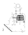
- FIGS. 1 schematically a device according to the invention is shown
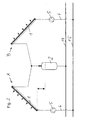
- Fig. 2 shows an alternative embodiment.
- the inventive device of Fig. 1 consists of a solar collector 1 and a storage tank 2, and a heating system 3 for a building not shown in detail.
- the heating system 3 may be a system of radiators, or a floor or wall heating, in a manner known per se.
- the heating of the heat transfer medium can be done directly, for example, by a heat pump or other device, but it can also be the heat transfer medium in the storage tank 2 are heated by a heat exchanger or an electric heater.
- the storage container 2 is connected via a supply line 4 with a feed pump 5 with the solar collector 1 in connection.
- a return line 6 is attached, which opens into the storage container 2.
- the return line 6 continues into a stratification tube 7, which has a multiplicity of vertically arranged return flow openings 7a.
- the solar collector 1 is arranged at a height h above the storage container 2.
- the heating system consists of a Bank Arthurssystem .9 with a heating pump 8, which is connected directly to the storage tank 2 and accordingly flows through the same heat transfer medium, such as the solar collector. 1
- a spiral tube heat exchanger 10 for the hot water preparation is provided in the storage container 2, which extends in a conventional manner vertically over a substantial portion of the storage container 2.
- the storage container 2 has an upper portion 12 in which a gas, for example air, is present.
- the region 13 is filled with heat transfer medium, which has a free surface 11. It is essential that the return line 6 or the layer tube 7 has an opening which lies above a maximum filling level for the storage container 2.
- the feed pump 5 is put into operation and the solar collector 1 is filled with heat transfer medium, via the return line 6 flows back into the storage container 2.
- the back-flowing heat transfer medium has a higher temperature than the heat transfer medium present in the storage tank 2
- the recirculated heat transfer medium from the solar collector 2 at the highest point of the laminated tube 7 will flow and thus produce a temperature stratification in the storage tank 2.
- the temperature of the refluxing heat transfer medium between the temperature in the lower portion of the storage container 2 and the temperature of the heat transfer medium in the upper portion of the storage container 2 the heat transfer medium will flow mainly between these areas.
- the storage container 2 is therefore charged while maintaining the temperature stratification substantially from top to bottom.
- an air space is formed by air under a pressure of about 3 bar, wherein the volume of this air space is in any case greater than the volume of the solar collector 1 and the relevant line sections 4 and 6 of the solar collector.
- the air space 12 in the storage container 2 also serves as a compensation chamber for the heating system 3, which is kept in this way at a suitable pressure level.
- the system pressure depends on the temperature of the heat transfer medium. Due to the relatively large-sized airspace, these fluctuations are low and are normally in a range of a few tenths bar.
- Fig. 2 In the variant of Fig. 2 are two solar systems A and B connected in parallel to a flow line 14 and a return line 15 of a heating system not shown in detail. These systems A and B each consist of a solar collector 1 with a common storage tank 2, and a feed pump 5 in the supply line 4. The two solar systems A and B can be operated independently of each other in this way. It is also possible to provide a separate storage container 2 for each of the solar collectors 1.
- the storage container 2 can be made relatively small, in the extreme case so that in operation, i. in flooded solar collector 1, only a minimum amount of heat transfer medium in the storage container 2 is present.
- the system according to the invention is very robust, since temperatures of 120 ° C and more can be allowed in the solar collector. But even with an oversupply of solar radiation and at the same time lack of consumption overheating can be easily avoided by simply switching off the feed pump 5, since in this way a further heat input into the system is prevented.
Description
Die Erfindung betrifft ein Verfahren gemäß dem Oberbegriff von Patentanspruch 1. Zur Bereitstellung von Wärme zur Beheizung von Gebäuden und gegebenenfalls zur Erwärmung von Brauchwasser über einen Solarkollektor ist dabei ein Verfahren vorgesehen, bei dem der Solarkollektor bei Sonneneinstrahlung mit einem Wärmeträgermedium gefüllt und durchströmt wird, um das Wärmeträgermedium zu erwärmen, und bei dem der Solarkollektor ansonsten entleert wird, wobei das Wärmeträgermedium in einem Speicherbehälter gesammelt wird, und wobei das Wärmeträgermedium im Speicherbehälter und im Solarkollektor unter erhöhtem Druck gehalten wird.The invention relates to a method according to the preamble of claim 1. To provide heat for heating buildings and optionally for heating service water via a solar collector while a method is provided, in which the solar collector is filled with solar radiation with a heat transfer medium and flows through to to heat the heat transfer medium, and in which the solar collector is otherwise emptied, wherein the heat transfer medium is collected in a storage container, and wherein the heat transfer medium in the storage tank and in the solar collector is kept under increased pressure.
Die Standardbauweise von Solaranlagen besteht darin, dass ein Wärmeträgermedium durch den Solarkollektor in einem geschlossenen Kreislauf geführt wird. Da der Solarkollektor dabei stets gefüllt bleibt, ist es erforderlich, entsprechende technische Vorkehrungen zu treffen, um einen sicheren Betrieb zu gewährleisten, wie etwa Frostschutzmittel, Ausgleichsbehälter und dergleichen. In bestimmten Anwendungsfällen ist jedoch eine Vereinfachung dieses Aufbaus erwünscht, um eine besondere Robustheit und Kosteneffizienz zu erreichen. Aus diesem Grund sind Solaranlagen entwickelt worden, bei denen der Solarkollektor nur bei Betrieb mit Wärmeträgermedium geflutet ist und ansonsten entleert wird. Eine solche Anlange ist in der
Nachteilig der gegebenen Lösung ist, dass für die Nutzung der Wärme in einer Gebäudeheizung mindestens ein Wärmetauscher erforderlich ist, und dass es bei starker Sonneneinstrahlung und geringem Verbrauch zu Verlusten an Wärmeträgermedium durch Verdunsten kommen kann. Zusätzlich kann durch die Aufnahme von Sauerstoff aus der Luft Korrosion auftreten.The disadvantage of the given solution is that for the use of heat in a building heating at least one heat exchanger is required, and that it can come to evaporate at high solar radiation and low consumption losses of heat transfer medium. In addition, the absorption of oxygen from the air can cause corrosion.
Darüber hinaus zeigt die
Aus der
Aufgabe der vorliegenden Erfindung ist es, diese Nachteile zu vermeiden und eine Lösung anzugeben, die einfach, kostengünstig, robust und effizient zu gleich ist. Mit robust ist nicht nur eine Unempfindlichkeit im mechanischen Sinne gemeint, sondern auch ein unproblematisches Regelverhalten. Effizient bedeutet hauptsächlich einen hohen Wirkungsgrad und eine gute Ausnützung des Wärmeangebots.Object of the present invention is to avoid these disadvantages and to provide a solution that is simple, inexpensive, robust and efficient to equal. Robust not only means insensitivity in the mechanical sense, but also an unproblematic control behavior. Efficient means mainly a high efficiency and a good utilization of the heat supply.
Erfindungsgemäß ist das Verfahren gemäß Patentanspruch 1 dadurch gekennzeichnet, dass der Speicherbehälter in allen Betriebszuständen teilweise mit Wärmeträgermedium und teilweise mit Gas gefüllt ist dass das Wärmeträgermedium direkt zur Beheizung eines Gebäudes aus dem Speicherbehälter entnommen wird. Zusätzlich kann Brauchwasser erwärmt werden.According to the method according to claim 1, characterized in that the storage container is partially filled with heat transfer medium and partially with gas in all operating conditions that the heat transfer medium is removed directly for heating a building from the storage container. In addition, service water can be heated.
Wesentlich an der vorliegenden Erfindung ist die Tatsache, dass das Gesamtsystem stets unter einem Druck gehalten wird, wodurch mehrere Ziele gleichzeitig erreicht werden.Essential to the present invention is the fact that the overall system is always kept under pressure, whereby several goals are achieved simultaneously.
Durch die erfindungsgemäße Lösung kann das unter Druck vorliegende Wärmeträgermedium direkt zur Gebäudeheizung verwendet werden, so dass jeglicher Wärmetauscher im Heizsystem vermieden werden kann. Typischerweise bedeutet ein Wärmetauscher einen Temperaturverlust von etwa 3 K bis 5 K, was zu einer entsprechenden Einbuße im Wirkungsgrad führt. Gleichzeitig aber entfällt bei der erfindungsgemäßen Lösung die Notwendigkeit für den Einbau von herkömmlichen Ausgleichsbehältern, da der Speicherbehälter selbst als Ausgleichsbehälter dient. Durch die Erhöhung des Siedepunktes des Wärmeträgermediums kann dieses im Solarkollektor auf höhere Temperaturen erwärmt werden. Typischerweise besteht das Wärmeträgermedium hauptsächlich aus Wasser, das unter Normaldruck bei 100°C siedet. Mit der erfindungsgemäßen Lösung können durchaus auch Temperaturen von 120°C bis 140°C zugelassen werden. In Folge des geschlossenen Systems kommt es zu keinen Verlusten an Wärmeträgermedium.As a result of the solution according to the invention, the heat transfer medium under pressure can be used directly for heating the building, so that any heat exchanger in the heating system can be avoided. Typically, a heat exchanger means a temperature loss of about 3 K to 5 K, resulting in a corresponding loss of efficiency. At the same time, however, eliminates the need for the installation of conventional surge tanks in the inventive solution, since the storage container itself serves as a surge tank. By increasing the boiling point of the heat transfer medium this can be heated in the solar collector to higher temperatures. Typically, the heat transfer medium consists mainly of water, which boils under normal pressure at 100 ° C. Temperatures of 120 ° C to 140 ° C can certainly be allowed with the solution according to the invention. As a result of the closed system, there is no loss of heat transfer medium.
Besonders vorteilhaft ist es in diesem Zusammenhang, wenn im Speicherbehälter eine Temperaturschichtung aufrecht erhalten wird. Auf diese Weise kann die Gesamtenergieeffizienz besonders gesteigert werden, da in der Regel auch bei geringer Sonneneinstrahlung Energie auf niedrigem Temperaturniveau genutzt werden kann.It is particularly advantageous in this context if a temperature stratification is maintained in the storage container. In this way, the overall energy efficiency can be increased, since energy can be used at a low temperature level even with low solar radiation in the rule.
Ein besonders einfacher Aufbau wird erreicht, wenn das Wärmeträgermedium im Speicherbehälter eine freie Oberfläche aufweist. Membranen oder dergleichen sind zur Trennung von Luft und Wärmeträgermedium nicht erforderlich.A particularly simple construction is achieved if the heat transfer medium in the storage container has a free surface. Membranes or the like are not required for the separation of air and heat transfer medium.
Gemäß einer Variante der Erfindung können mehrere Solarkollektoren und/oder Speicherbehälter parallel geschaltet werden. Auf diese Weise ist es nicht nur möglich, die Gesamtleistung zu erhöhen, sondern auch einer Ost-West-Ausrichtung der Solarkollektoren Rechnung zu tragen, wenn dies aufgrund von baulichen Gegebenheiten erforderlich ist.According to a variant of the invention, a plurality of solar collectors and / or storage containers can be connected in parallel. In this way, it is not only possible to increase the overall performance, but also to take into account an east-west orientation of the solar collectors, if this is necessary due to structural conditions.
Gemäß einer besonders bevorzugten Ausführungsvariante der Erfindung ist vorgesehen, dass Brauchwasser erwärmt wird, indem es durch einen Wärmetauscher im Speicherbehälter geführt wird. Auf diese Weise kann mit einfachen Mitteln eine Solaranlage dargestellt werden, die sowohl zur Beheizung als auch zur Warmwasserbereitung dient. Durch einen Spiralrohrwärmetauscher der sich in vertikaler Richtung über einen wesentlichen Teil des Speicherbehälters streckt, kann die Temperaturschichtung des Wärmeträgermediums im Speicherbehälter optimal ausgenützt werden.According to a particularly preferred embodiment of the invention, it is provided that service water is heated by being passed through a heat exchanger in the storage tank. In this way, a solar system can be displayed with simple means, which serves both for heating and for hot water. By a spiral tube heat exchanger which stretches in the vertical direction over a substantial part of the storage container, the temperature stratification of the heat transfer medium in the storage container can be optimally utilized.
Im einfachsten Fall wird als Gas Luft eingesetzt, wobei aber auch Systeme mit Stickstofffüllung sinnvoll sind. Der Druck im System wird typischerweise auf einen Wert zwischen 2 bar und 5 bar eingestellt.In the simplest case, air is used as the gas, although systems with nitrogen filling are also useful. The pressure in the system is typically set to a value between 2 bar and 5 bar.
Weiters betrifft die vorliegende Erfindung eine Vorrichtung zur Durchführung des obigen Verfahrens gemäß Patentanspruch 8. Diese Vorrichtung ist zur Bereitstellung von Wärme zur Beheizung von Gebäuden mit einem Solarkollektor, einem Speicherbehälter und einem Heizungssystem versehen, wobei das System aus Solarkollektor, Speicherbehälter und Heizungssystem als geschlossenes, unter Druck mit einem einzigen Wärmeträgermedium füllbares System ausgebildet ist.Furthermore, the present invention relates to an apparatus for carrying out the above method according to claim 8. This apparatus is provided for providing heat for heating buildings with a solar collector, a storage tank and a heating system, wherein the system of solar collector, storage tank and heating system as a closed, formed under pressure with a single heat transfer medium fillable system.
Erfindungsgemäß ist vorgesehen, dass der Solarkollektor mit einer Einrichtung zur betriebsmäßigen Entleerung versehen ist, dass der Speicherbehälter zusätzlich zum Wärmeträgermedium mit Gas füllbar ist, dass eine Zufuhrleitung-zum Solarkollektor vorgesehen ist, die vom unteren Bereich des Speicherbehälters ausgeht und in der eine Förderpumpe vorgesehen ist, und dass eine Rückführleitung vorgesehen ist, die in einen oberen Bereich des Speicherbehälters mündet. Die erfindungsgemäße Vorrichtung ist so ausgebildet, dass eine Zuführleitung zum Solar- x kollektor vorgesehen ist, die vom unteren Bereich des Speicherbehälters ausgeht und in der eine Förderpumpe vorgesehen ist, und dass eine Rückführleitung vorgesehen ist, die in einen oberen Bereich des Speicherbehälters mündet, der oberhalb einer maximalen Füllgrenze für das Wärmeträgermedium liegt. Auf diese Weise kann die Belüftung des Solarkollektors in einfacher Weise durch Abschalten der Förderpumpe erfolgen, wenn diese so ausgebildet ist, dass sie entgegen der Förderrichtung durchströmbar ist. Wichtig dabei ist, dass der Solarkollektor ausreichend oberhalb des Speicherbehälters angeordnet ist.According to the invention, the solar collector is provided with a device for operational emptying, that the storage container can be filled with gas in addition to the heat transfer medium, that a supply line to the solar collector is provided, which starts from the lower region of the storage container and in which a feed pump is provided , And that a return line is provided, which opens into an upper region of the storage container. The device according to the invention is designed so that a supply line to the solar collector is provided, which starts from the lower region of the storage container and in which a delivery pump is provided, and that a return line is provided, which opens into an upper region of the storage container above a maximum filling limit for the heat transfer medium. In this way, the ventilation of the solar collector can be done in a simple manner by switching off the feed pump, if they are formed is that it can be flowed through against the conveying direction. It is important that the solar collector is arranged sufficiently above the storage container.
In der Folge wird die vorliegende Erfindung anhand der in den Figuren dargestellten Ausführungsbeispiele näher erläutert. In
Die erfindungsgemäße Vorrichtung von
Um bei Bedarf eine sichere Rückströmung des Wärmeträgermediums zu gewährleisten, ist der Solarkollektor 1 um eine Höhe h oberhalb des Speicherbehälters 2 angeordnet.In order to ensure a safe return flow of the heat transfer medium when needed, the solar collector 1 is arranged at a height h above the
Das Heizungssystem besteht aus einem Heizleitungssystem .9 mit einer Heizungspumpe 8, das direkt an den Speicherbehälter 2 angeschlossen ist und dementsprechend mit dem selben Wärmeträgermedium durchströmt wird, wie der Solarkollektor 1.The heating system consists of a Heizleitungssystem .9 with a heating pump 8, which is connected directly to the
Weiters ist im Speicherbehälter 2 ein Spiralrohrwärmetauscher 10 für die Warmwasserbereitung vorgesehen, der sich in an sich bekannter Weise vertikal über einen wesentlichen Abschnitt des Speicherbehälters 2 erstreckt.Furthermore, a spiral
Der Speicherbehälter 2 besitzt einen oberen Abschnitt 12 in dem ein Gas, beispielsweise Luft, vorliegt. Der Bereich 13 ist mit Wärmeträgermedium gefüllt, das eine freie Oberfläche 11 aufweist. Wesentlich ist, dass die Rückführleitung 6 bzw. das Schichtrohr 7 eine Öffnung aufweist, die oberhalb einer maximalen Füllhöhe für den Speicherbehälter 2 liegt.The
In der Folge wird der Betrieb der erfindungsgemäßen Vorrichtung erläutert. Bei entsprechender Sonneneinstrahlung wird die Förderpumpe 5 in Betrieb genommen und der Solarkollektor 1 wird mit Wärmeträgermedium gefüllt, das über die Rückführleitung 6 in den Speicherbehälter 2 zurückströmt. Solange das rückströmende Wärmeträgermedium eine höhere Temperatur aufweist, als das im Speicherbehälter 2 vorliegende Wärmeträgermedium, wird das vom Solarkollektor 2 rückgeführte Wärmeträgermedium an der höchsten Stelle des Schichtrohrs 7 ausströmen und somit eine Temperaturschichtung im Speicherbehälter 2 erzeugen. Liegt jedoch die Temperatur des rückströmenden Wärmeträgermediums zwischen der Temperatur im unteren Abschnitt des Speicherbehälters 2 und der Temperatur des Wärmeträgermediums im oben Abschnitt des Speicherbehälters 2, so wird das Wärmeträgermedium hauptsächlich zwischen diesen Bereichen ausströmen. Der Speicherbehälter 2 wird daher unter Aufrechterhaltung der Temperaturschichtung im Wesentlichen von oben nach unten aufgeladen.In the following, the operation of the device according to the invention will be explained. With appropriate sunlight, the
Im oberen Bereich 12 des Speicherbehälters 2 ist ein Luftraum ausgebildet, indem Luft unter einem Druck von etwa 3 bar vorliegt, wobei das Volumen dieses Luftraumes jedenfalls größer ist als das Volumen des Solarkollektors 1 und der relevanten Leitungsabschnitte 4 zum bzw. 6 vom Solarkollektor 1. Wird nun die Förderpumpe 5 abgeschaltet, so strömt das Wärmeträgermedium entgegen der Förderrichtung der Förderpumpe 5 in den Speicherbehälter 2 zurück und es wird über die Rücklaufleitung 6 Luft aus dem oberen Abschnitt 12 des Speicherbehälters 2 in den Solarkollektor 1 nachgesaugt. Dadurch steigt der Flüssigkeitsspiegel 11 im Speicherbehälter 2 an und der Luftraum wird verkleinert. Das System wird jedoch so betrieben, dass jedenfalls ein minimaler Luftraum im Speicherbehälter 2 verbleibt. Durch die vollständige Entleerung des Solarkollektors 1 wird die Gefahr des Einfrierens bei entsprechend niedrigen Temperaturen völlig vermieden.In the
Der Luftraum 12 im Speicherbehälter 2 dient gleichzeitig auch als Ausgleichsraum für das Heizungssystem 3, das auf diese Weise auf einem passenden Druckniveau gehalten wird.The
Da das System in sich geschlossen ist, hängt der Systemdruck selbstverständlich von der Temperatur des Wärmeträgermediums ab. Aufgrund des relativ groß dimensionierten Luftraumes sind diese Schwankungen jedoch gering und liegen im Normalfall in einem Bereich von wenigen zehntel bar.Of course, since the system is self-contained, the system pressure depends on the temperature of the heat transfer medium. Due to the relatively large-sized airspace, these fluctuations are low and are normally in a range of a few tenths bar.
Bei der Variante von
Bei Heizsystemen mit großer eigener Speicherkapazität, wie etwa Fußbodenheizungen, können die Speicherbehälter 2 relativ klein ausgeführt werden, im Extremfall so, dass in Betrieb, d.h. bei geflutetem Solarkollektor 1 nur eine Minimalmenge an Wärmeträgermedium im Speicherbehälter 2 vorliegt.In heating systems with large own storage capacity, such as underfloor heating, the
Das erfindungsgemäße System ist sehr robust, da auch Temperaturen von 120°C und mehr im Solarkollektor zugelassen werden können. Aber auch bei einem Überangebot an Solareinstrahlung und gleichzeitig mangelndem Verbrauch kann eine Überhitzung durch einfaches Abschalten der Förderpumpe 5 leicht vermieden werden, da auf diese Weise eine weitere Wärmezufuhr in das System unterbunden wird.The system according to the invention is very robust, since temperatures of 120 ° C and more can be allowed in the solar collector. But even with an oversupply of solar radiation and at the same time lack of consumption overheating can be easily avoided by simply switching off the
Claims (13)
- A method for providing heat for heating buildings and optionally for heating industrial water via a solar collector (1), in which the solar collector (1) is filled and permeated with a thermal carrier medium in the event of incident solar radiation, in order to heat the thermal carrier medium, and in which the solar collector (1) is otherwise emptied, the thermal carrier medium being collected in a storage reservoir (2), and the thermal carrier medium being kept under elevated pressure in the storage reservoir (2) and in the solar collector (1), characterised in that the storage reservoir (2) is partially filled with thermal carrier medium and partially filled with gas in all operating states, and the thermal carrier medium is removed directly from the storage reservoir (2) to heat the building.
- The method according to claim 1, characterised in that the thermal carrier medium provided in the storage reservoir (2) has a free surface (11).
- The method according to one of claims 1 or 2, characterised in that a temperature stratification is maintained in the storage reservoir (2).
- The method according to one of claims 1 to 3, characterised in that industrial water is heated, in that it is conducted through a heat exchanger (10) in the storage reservoir (2).
- The method according to one of claims 1 to 4, characterised in that multiple solar collectors (1) and/or storage reservoirs (2) are connected in parallel.
- The method according to one of claims 1 to 5, characterised in that air is used as the gas.
- The method according to one of claims 1 to 6, characterised in that the pressure in the system made of storage reservoir (2), solar collector (1), and heating system (3) is kept at a value between 2 and 5 bar.
- A device for providing heat for heating buildings having a solar collector (1), a storage reservoir (2), and a heating system (3), the solar collector (1) being provided with an apparatus for operational emptying, the system made of solar collector (1), storage reservoir (2), and heating system (3) being implemented as a closed system fillable under pressure with a single thermal carrier medium, characterised in that the solar collector (1) is provided with a device for operational emptying, the storage reservoir (2) is fillable with gas in addition to the thermal carrier medium, a supply line (4) to the solar collector (1) is provided, which originates from the lower area (13) of the storage reservoir (2) and in which a delivery pump (5) is provided, and a return line (6) is provided, which opens into an upper area (12) of the storage reservoir (2), which is located above a maximum fill limit for the thermal carrier medium.
- The device according to claim 8, characterised in that the storage reservoir (2) has a gas space (12) in its upper section, which is implemented directly above a surface (11) of the thermal carrier medium.
- The device according to one of claims 8 or 9, characterised in that multiple storage reservoirs (2) are connected in parallel.
- The device according to one of claims 8 to 10, characterised in that a heat exchanger (10) for heating industrial water is arranged in the storage reservoir (2).
- The device according to one of claims 8 to 11, characterised in that means for maintaining a temperature stratification are arranged in the storage reservoir (2).
- The device according to claim 12, characterised in that the means for maintaining a temperature stratification is implemented as a stratification pipe (7).
Priority Applications (1)
| Application Number | Priority Date | Filing Date | Title |
|---|---|---|---|
| PL10723609T PL2446196T3 (en) | 2009-06-25 | 2010-06-16 | Method for providing heat |
Applications Claiming Priority (2)
| Application Number | Priority Date | Filing Date | Title |
|---|---|---|---|
| ATA978/2009A AT508480B1 (en) | 2009-06-25 | 2009-06-25 | PROCESS FOR PROVIDING HEAT |
| PCT/EP2010/058438 WO2010149550A2 (en) | 2009-06-25 | 2010-06-16 | Method for providing heat |
Publications (2)
| Publication Number | Publication Date |
|---|---|
| EP2446196A2 EP2446196A2 (en) | 2012-05-02 |
| EP2446196B1 true EP2446196B1 (en) | 2013-07-24 |
Family
ID=43386947
Family Applications (1)
| Application Number | Title | Priority Date | Filing Date |
|---|---|---|---|
| EP10723609.3A Not-in-force EP2446196B1 (en) | 2009-06-25 | 2010-06-16 | Method for providing heat |
Country Status (6)
| Country | Link |
|---|---|
| US (1) | US20120125320A1 (en) |
| EP (1) | EP2446196B1 (en) |
| AT (1) | AT508480B1 (en) |
| ES (1) | ES2430646T3 (en) |
| PL (1) | PL2446196T3 (en) |
| WO (1) | WO2010149550A2 (en) |
Cited By (1)
| Publication number | Priority date | Publication date | Assignee | Title |
|---|---|---|---|---|
| KR20160019003A (en) | 2014-08-08 | 2016-02-18 | 대성히트펌프 주식회사 | Compact hot water storage tank with diffuser and manufacturing method thereof |
Families Citing this family (5)
| Publication number | Priority date | Publication date | Assignee | Title |
|---|---|---|---|---|
| US20110041835A1 (en) * | 2009-08-21 | 2011-02-24 | James Wayne Blevins | Solar heat exchanger |
| DE102010009081A1 (en) * | 2010-02-24 | 2011-08-25 | Helmut Bälz GmbH, 74076 | Heat generator group with jet pump control |
| CN104101117B (en) * | 2013-04-15 | 2016-03-16 | 刘在祥 | The nitrogen charging equipment of panel solar shell and nitrogen filling method |
| WO2017209832A1 (en) * | 2016-06-03 | 2017-12-07 | A.O. Smith Corporation | Stratifier for tank-type water heater |
| CN107166476B (en) * | 2017-06-08 | 2019-06-07 | 东北大学 | A kind of heating system of high-pressure water tank combined absorption type heat pump |
Family Cites Families (19)
| Publication number | Priority date | Publication date | Assignee | Title |
|---|---|---|---|---|
| US3653429A (en) * | 1969-05-06 | 1972-04-04 | Hooker Chemical Corp | Water heating system |
| US3799145A (en) * | 1972-09-21 | 1974-03-26 | D Butterfield | Solar heating system |
| US4027821A (en) * | 1975-07-18 | 1977-06-07 | International Telephone And Telegraph Corporation | Solar heating/cooling system |
| FR2394765A1 (en) | 1976-12-03 | 1979-01-12 | Paul Bettinger | Solar heating arrangement control system - varies method of operation throughout day in accordance with signals from thermostats |
| US4237862A (en) * | 1978-03-27 | 1980-12-09 | Helios Corporation | Closed pressurized solar heating system with automatic solar collector drain-down |
| US4232655A (en) * | 1978-06-26 | 1980-11-11 | Owens-Illinois, Inc. | Solar energy collection |
| US4340033A (en) * | 1979-03-05 | 1982-07-20 | Stewart James M | Heat collecting, utilizing and storage apparatus and method |
| US4269167A (en) * | 1979-12-07 | 1981-05-26 | Embree John M | Closed pressurized solar heating system with automatic valveless solar collector drain-back |
| US4319561A (en) * | 1980-03-06 | 1982-03-16 | Owens-Illinois, Inc. | Solar energy collector assembly |
| US4385625A (en) * | 1981-03-02 | 1983-05-31 | Lee Kap Joong | Building heating system |
| DE3742910A1 (en) * | 1987-03-31 | 1988-10-20 | Alfred R Dr Ing Neugebauer | Heating system |
| US5823177A (en) * | 1996-01-16 | 1998-10-20 | Whitehead; John C. | Pumpless solar water heater with isolated pressurized storage |
| NL1013261C1 (en) * | 1999-10-11 | 2000-02-04 | Heatex Bv | System for solar heating of tap water with anti-Legionella facilities. |
| DE19953493C2 (en) * | 1999-11-06 | 2003-12-18 | Ht Helio Tech Gmbh | solar system |
| AT411707B (en) * | 2000-05-23 | 2004-04-26 | Demmerer Christian Ing | WATER-TANK |
| DE20206564U1 (en) * | 2002-04-25 | 2002-10-10 | Consolar Energiespeicher Und R | Air separator and idling aid for solar systems without antifreeze |
| PL356349A1 (en) * | 2002-09-27 | 2004-04-05 | Adam Skorut | Method of safe transfer of solar energy and low-pressure system for transmission of solar energy |
| FR2847663B3 (en) * | 2002-11-21 | 2005-02-18 | Sylvain Pelletier | CYLINDRO-PARABOLIC SOLAR SENSOR WITH TRACKING DEVICES, ATMOSPHERIC PROTECTION, CONNECTION TO A CLASSIC ELECTRIC WATER HEATER AND ANTIFREEZE PURGE |
| EP1840474A3 (en) * | 2006-03-29 | 2009-07-15 | Fafco Incorporated | Kit for solar water heating system |
-
2009
- 2009-06-25 AT ATA978/2009A patent/AT508480B1/en not_active IP Right Cessation
-
2010
- 2010-06-16 ES ES10723609T patent/ES2430646T3/en active Active
- 2010-06-16 PL PL10723609T patent/PL2446196T3/en unknown
- 2010-06-16 WO PCT/EP2010/058438 patent/WO2010149550A2/en active Application Filing
- 2010-06-16 US US13/380,177 patent/US20120125320A1/en not_active Abandoned
- 2010-06-16 EP EP10723609.3A patent/EP2446196B1/en not_active Not-in-force
Cited By (1)
| Publication number | Priority date | Publication date | Assignee | Title |
|---|---|---|---|---|
| KR20160019003A (en) | 2014-08-08 | 2016-02-18 | 대성히트펌프 주식회사 | Compact hot water storage tank with diffuser and manufacturing method thereof |
Also Published As
| Publication number | Publication date |
|---|---|
| WO2010149550A3 (en) | 2011-06-16 |
| WO2010149550A2 (en) | 2010-12-29 |
| AT508480B1 (en) | 2012-04-15 |
| EP2446196A2 (en) | 2012-05-02 |
| US20120125320A1 (en) | 2012-05-24 |
| PL2446196T3 (en) | 2013-12-31 |
| ES2430646T3 (en) | 2013-11-21 |
| AT508480A1 (en) | 2011-01-15 |
Similar Documents
| Publication | Publication Date | Title |
|---|---|---|
| EP2446196B1 (en) | Method for providing heat | |
| DE2712822A1 (en) | SOLAR HOT WATER TANK | |
| AT508481B1 (en) | METHOD FOR HEATING HOT WATER | |
| WO2012061865A2 (en) | Solar collector | |
| DE10028543B4 (en) | refrigeration unit | |
| DE2638834A1 (en) | Hot water supply system through triple heat exchanger - is served by solar absorber, heat pump and conventional boiler unit | |
| DE2804748B1 (en) | Heat-insulated container for warm water or similar Liquids | |
| DE2734521A1 (en) | Solar energy absorption system using heat pipes - having air cooling fans and ducts to avoid overheating in hot sunshine if power failure occurs | |
| DE102012102931A1 (en) | Water-bearing solar system has control device, which extracts hot water from lowest layer of stratified storage using anti-freeze protection, when temperature in collection tubes exceed predetermined temperature value | |
| EP2489945A2 (en) | Heat accumulator | |
| DE102008025612B4 (en) | Flat collector for solar heating for domestic hot water and / or for heating support | |
| DE102008036738B4 (en) | Flat plate collector foil | |
| EP1692435B1 (en) | Solar installation | |
| AT504399B1 (en) | ABSORPTION CHILLER | |
| DE3036244A1 (en) | HOT WATER TANK FOR A SOLAR COLLECTOR | |
| DE4440036C2 (en) | Heat exchange arrangement | |
| EP0096056B1 (en) | Installation for heating a liquid by solar power | |
| DE3015061A1 (en) | SOLAR COLLECTOR WITH OVERHEATING PROTECTION | |
| DE4123169C1 (en) | Frost protection for solar collectors - uses water replacing liq. on collector temp. dropping below preset level | |
| DE3003688A1 (en) | Solar collector system with heat carrier - solar collectors are connected with layered storage tank | |
| AT501612B1 (en) | METHOD FOR OPERATING A HOT WATER TREATMENT PLANT AND HOT WATER TREATMENT PLANT | |
| AT375171B (en) | HEAT CONVERTER, ESPECIALLY SOLAR ENERGY ABSORBER | |
| DE202021104052U1 (en) | Storage tanks for heating systems | |
| EP2405205A1 (en) | Gas separator in a solar installation for generating heat | |
| DE102009060428A1 (en) | Thermal system for building, has solar collector integrated into primary circuit, and primary and secondary circuits thermally coupled with each other by heat exchanger, where heat medium is transferred with antifreeze agent |
Legal Events
| Date | Code | Title | Description |
|---|---|---|---|
| PUAI | Public reference made under article 153(3) epc to a published international application that has entered the european phase |
Free format text: ORIGINAL CODE: 0009012 |
|
| 17P | Request for examination filed |
Effective date: 20111222 |
|
| AK | Designated contracting states |
Kind code of ref document: A2 Designated state(s): AL AT BE BG CH CY CZ DE DK EE ES FI FR GB GR HR HU IE IS IT LI LT LU LV MC MK MT NL NO PL PT RO SE SI SK SM TR |
|
| DAX | Request for extension of the european patent (deleted) | ||
| 17Q | First examination report despatched |
Effective date: 20121105 |
|
| GRAP | Despatch of communication of intention to grant a patent |
Free format text: ORIGINAL CODE: EPIDOSNIGR1 |
|
| INTG | Intention to grant announced |
Effective date: 20130416 |
|
| GRAS | Grant fee paid |
Free format text: ORIGINAL CODE: EPIDOSNIGR3 |
|
| GRAA | (expected) grant |
Free format text: ORIGINAL CODE: 0009210 |
|
| AK | Designated contracting states |
Kind code of ref document: B1 Designated state(s): AL AT BE BG CH CY CZ DE DK EE ES FI FR GB GR HR HU IE IS IT LI LT LU LV MC MK MT NL NO PL PT RO SE SI SK SM TR |
|
| REG | Reference to a national code |
Ref country code: GB Ref legal event code: FG4D Free format text: NOT ENGLISH |
|
| REG | Reference to a national code |
Ref country code: CH Ref legal event code: EP |
|
| REG | Reference to a national code |
Ref country code: AT Ref legal event code: REF Ref document number: 623675 Country of ref document: AT Kind code of ref document: T Effective date: 20130815 |
|
| REG | Reference to a national code |
Ref country code: IE Ref legal event code: FG4D Free format text: LANGUAGE OF EP DOCUMENT: GERMAN |
|
| REG | Reference to a national code |
Ref country code: DE Ref legal event code: R096 Ref document number: 502010004138 Country of ref document: DE Effective date: 20130919 |
|
| REG | Reference to a national code |
Ref country code: ES Ref legal event code: FG2A Ref document number: 2430646 Country of ref document: ES Kind code of ref document: T3 Effective date: 20131121 |
|
| REG | Reference to a national code |
Ref country code: NL Ref legal event code: T3 |
|
| REG | Reference to a national code |
Ref country code: LT Ref legal event code: MG4D |
|
| REG | Reference to a national code |
Ref country code: PL Ref legal event code: T3 |
|
| PG25 | Lapsed in a contracting state [announced via postgrant information from national office to epo] |
Ref country code: IS Free format text: LAPSE BECAUSE OF FAILURE TO SUBMIT A TRANSLATION OF THE DESCRIPTION OR TO PAY THE FEE WITHIN THE PRESCRIBED TIME-LIMIT Effective date: 20131124 Ref country code: PT Free format text: LAPSE BECAUSE OF FAILURE TO SUBMIT A TRANSLATION OF THE DESCRIPTION OR TO PAY THE FEE WITHIN THE PRESCRIBED TIME-LIMIT Effective date: 20131125 Ref country code: LT Free format text: LAPSE BECAUSE OF FAILURE TO SUBMIT A TRANSLATION OF THE DESCRIPTION OR TO PAY THE FEE WITHIN THE PRESCRIBED TIME-LIMIT Effective date: 20130724 Ref country code: SE Free format text: LAPSE BECAUSE OF FAILURE TO SUBMIT A TRANSLATION OF THE DESCRIPTION OR TO PAY THE FEE WITHIN THE PRESCRIBED TIME-LIMIT Effective date: 20130724 Ref country code: NO Free format text: LAPSE BECAUSE OF FAILURE TO SUBMIT A TRANSLATION OF THE DESCRIPTION OR TO PAY THE FEE WITHIN THE PRESCRIBED TIME-LIMIT Effective date: 20131024 Ref country code: CY Free format text: LAPSE BECAUSE OF FAILURE TO SUBMIT A TRANSLATION OF THE DESCRIPTION OR TO PAY THE FEE WITHIN THE PRESCRIBED TIME-LIMIT Effective date: 20130821 Ref country code: HR Free format text: LAPSE BECAUSE OF FAILURE TO SUBMIT A TRANSLATION OF THE DESCRIPTION OR TO PAY THE FEE WITHIN THE PRESCRIBED TIME-LIMIT Effective date: 20130724 |
|
| PG25 | Lapsed in a contracting state [announced via postgrant information from national office to epo] |
Ref country code: LV Free format text: LAPSE BECAUSE OF FAILURE TO SUBMIT A TRANSLATION OF THE DESCRIPTION OR TO PAY THE FEE WITHIN THE PRESCRIBED TIME-LIMIT Effective date: 20130724 Ref country code: GR Free format text: LAPSE BECAUSE OF FAILURE TO SUBMIT A TRANSLATION OF THE DESCRIPTION OR TO PAY THE FEE WITHIN THE PRESCRIBED TIME-LIMIT Effective date: 20131025 Ref country code: FI Free format text: LAPSE BECAUSE OF FAILURE TO SUBMIT A TRANSLATION OF THE DESCRIPTION OR TO PAY THE FEE WITHIN THE PRESCRIBED TIME-LIMIT Effective date: 20130724 Ref country code: SI Free format text: LAPSE BECAUSE OF FAILURE TO SUBMIT A TRANSLATION OF THE DESCRIPTION OR TO PAY THE FEE WITHIN THE PRESCRIBED TIME-LIMIT Effective date: 20130724 |
|
| PG25 | Lapsed in a contracting state [announced via postgrant information from national office to epo] |
Ref country code: CY Free format text: LAPSE BECAUSE OF FAILURE TO SUBMIT A TRANSLATION OF THE DESCRIPTION OR TO PAY THE FEE WITHIN THE PRESCRIBED TIME-LIMIT Effective date: 20130724 |
|
| PG25 | Lapsed in a contracting state [announced via postgrant information from national office to epo] |
Ref country code: DK Free format text: LAPSE BECAUSE OF FAILURE TO SUBMIT A TRANSLATION OF THE DESCRIPTION OR TO PAY THE FEE WITHIN THE PRESCRIBED TIME-LIMIT Effective date: 20130724 Ref country code: RO Free format text: LAPSE BECAUSE OF FAILURE TO SUBMIT A TRANSLATION OF THE DESCRIPTION OR TO PAY THE FEE WITHIN THE PRESCRIBED TIME-LIMIT Effective date: 20130724 Ref country code: CZ Free format text: LAPSE BECAUSE OF FAILURE TO SUBMIT A TRANSLATION OF THE DESCRIPTION OR TO PAY THE FEE WITHIN THE PRESCRIBED TIME-LIMIT Effective date: 20130724 Ref country code: EE Free format text: LAPSE BECAUSE OF FAILURE TO SUBMIT A TRANSLATION OF THE DESCRIPTION OR TO PAY THE FEE WITHIN THE PRESCRIBED TIME-LIMIT Effective date: 20130724 Ref country code: SK Free format text: LAPSE BECAUSE OF FAILURE TO SUBMIT A TRANSLATION OF THE DESCRIPTION OR TO PAY THE FEE WITHIN THE PRESCRIBED TIME-LIMIT Effective date: 20130724 |
|
| PLBE | No opposition filed within time limit |
Free format text: ORIGINAL CODE: 0009261 |
|
| STAA | Information on the status of an ep patent application or granted ep patent |
Free format text: STATUS: NO OPPOSITION FILED WITHIN TIME LIMIT |
|
| 26N | No opposition filed |
Effective date: 20140425 |
|
| REG | Reference to a national code |
Ref country code: DE Ref legal event code: R097 Ref document number: 502010004138 Country of ref document: DE Effective date: 20140425 |
|
| PGFP | Annual fee paid to national office [announced via postgrant information from national office to epo] |
Ref country code: ES Payment date: 20140513 Year of fee payment: 5 Ref country code: CH Payment date: 20140612 Year of fee payment: 5 Ref country code: IT Payment date: 20140620 Year of fee payment: 5 Ref country code: DE Payment date: 20140611 Year of fee payment: 5 |
|
| PGFP | Annual fee paid to national office [announced via postgrant information from national office to epo] |
Ref country code: BE Payment date: 20140612 Year of fee payment: 5 Ref country code: NL Payment date: 20140610 Year of fee payment: 5 |
|
| PGFP | Annual fee paid to national office [announced via postgrant information from national office to epo] |
Ref country code: FR Payment date: 20140609 Year of fee payment: 5 |
|
| PG25 | Lapsed in a contracting state [announced via postgrant information from national office to epo] |
Ref country code: MC Free format text: LAPSE BECAUSE OF FAILURE TO SUBMIT A TRANSLATION OF THE DESCRIPTION OR TO PAY THE FEE WITHIN THE PRESCRIBED TIME-LIMIT Effective date: 20130724 Ref country code: LU Free format text: LAPSE BECAUSE OF FAILURE TO SUBMIT A TRANSLATION OF THE DESCRIPTION OR TO PAY THE FEE WITHIN THE PRESCRIBED TIME-LIMIT Effective date: 20140616 |
|
| GBPC | Gb: european patent ceased through non-payment of renewal fee |
Effective date: 20140616 |
|
| REG | Reference to a national code |
Ref country code: IE Ref legal event code: MM4A |
|
| PG25 | Lapsed in a contracting state [announced via postgrant information from national office to epo] |
Ref country code: IE Free format text: LAPSE BECAUSE OF NON-PAYMENT OF DUE FEES Effective date: 20140616 |
|
| PG25 | Lapsed in a contracting state [announced via postgrant information from national office to epo] |
Ref country code: GB Free format text: LAPSE BECAUSE OF NON-PAYMENT OF DUE FEES Effective date: 20140616 |
|
| REG | Reference to a national code |
Ref country code: PL Ref legal event code: LAPE |
|
| PG25 | Lapsed in a contracting state [announced via postgrant information from national office to epo] |
Ref country code: PL Free format text: LAPSE BECAUSE OF NON-PAYMENT OF DUE FEES Effective date: 20140616 |
|
| REG | Reference to a national code |
Ref country code: DE Ref legal event code: R119 Ref document number: 502010004138 Country of ref document: DE |
|
| PG25 | Lapsed in a contracting state [announced via postgrant information from national office to epo] |
Ref country code: IT Free format text: LAPSE BECAUSE OF NON-PAYMENT OF DUE FEES Effective date: 20150616 |
|
| REG | Reference to a national code |
Ref country code: CH Ref legal event code: PL |
|
| REG | Reference to a national code |
Ref country code: NL Ref legal event code: MM Effective date: 20150701 |
|
| PG25 | Lapsed in a contracting state [announced via postgrant information from national office to epo] |
Ref country code: MT Free format text: LAPSE BECAUSE OF FAILURE TO SUBMIT A TRANSLATION OF THE DESCRIPTION OR TO PAY THE FEE WITHIN THE PRESCRIBED TIME-LIMIT Effective date: 20130724 |
|
| REG | Reference to a national code |
Ref country code: FR Ref legal event code: ST Effective date: 20160229 |
|
| PG25 | Lapsed in a contracting state [announced via postgrant information from national office to epo] |
Ref country code: LI Free format text: LAPSE BECAUSE OF NON-PAYMENT OF DUE FEES Effective date: 20150630 Ref country code: DE Free format text: LAPSE BECAUSE OF NON-PAYMENT OF DUE FEES Effective date: 20160101 Ref country code: CH Free format text: LAPSE BECAUSE OF NON-PAYMENT OF DUE FEES Effective date: 20150630 Ref country code: SM Free format text: LAPSE BECAUSE OF FAILURE TO SUBMIT A TRANSLATION OF THE DESCRIPTION OR TO PAY THE FEE WITHIN THE PRESCRIBED TIME-LIMIT Effective date: 20130724 Ref country code: NL Free format text: LAPSE BECAUSE OF NON-PAYMENT OF DUE FEES Effective date: 20150701 |
|
| PG25 | Lapsed in a contracting state [announced via postgrant information from national office to epo] |
Ref country code: FR Free format text: LAPSE BECAUSE OF NON-PAYMENT OF DUE FEES Effective date: 20150630 |
|
| PG25 | Lapsed in a contracting state [announced via postgrant information from national office to epo] |
Ref country code: BG Free format text: LAPSE BECAUSE OF FAILURE TO SUBMIT A TRANSLATION OF THE DESCRIPTION OR TO PAY THE FEE WITHIN THE PRESCRIBED TIME-LIMIT Effective date: 20130724 |
|
| REG | Reference to a national code |
Ref country code: ES Ref legal event code: FD2A Effective date: 20160728 |
|
| PG25 | Lapsed in a contracting state [announced via postgrant information from national office to epo] |
Ref country code: HU Free format text: LAPSE BECAUSE OF FAILURE TO SUBMIT A TRANSLATION OF THE DESCRIPTION OR TO PAY THE FEE WITHIN THE PRESCRIBED TIME-LIMIT; INVALID AB INITIO Effective date: 20100616 Ref country code: TR Free format text: LAPSE BECAUSE OF FAILURE TO SUBMIT A TRANSLATION OF THE DESCRIPTION OR TO PAY THE FEE WITHIN THE PRESCRIBED TIME-LIMIT Effective date: 20130724 |
|
| REG | Reference to a national code |
Ref country code: AT Ref legal event code: MM01 Ref document number: 623675 Country of ref document: AT Kind code of ref document: T Effective date: 20150616 |
|
| PG25 | Lapsed in a contracting state [announced via postgrant information from national office to epo] |
Ref country code: ES Free format text: LAPSE BECAUSE OF NON-PAYMENT OF DUE FEES Effective date: 20150617 Ref country code: AT Free format text: LAPSE BECAUSE OF NON-PAYMENT OF DUE FEES Effective date: 20150616 |
|
| PG25 | Lapsed in a contracting state [announced via postgrant information from national office to epo] |
Ref country code: BE Free format text: LAPSE BECAUSE OF NON-PAYMENT OF DUE FEES Effective date: 20150630 |
|
| PG25 | Lapsed in a contracting state [announced via postgrant information from national office to epo] |
Ref country code: MK Free format text: LAPSE BECAUSE OF FAILURE TO SUBMIT A TRANSLATION OF THE DESCRIPTION OR TO PAY THE FEE WITHIN THE PRESCRIBED TIME-LIMIT Effective date: 20130724 |
|
| PG25 | Lapsed in a contracting state [announced via postgrant information from national office to epo] |
Ref country code: AL Free format text: LAPSE BECAUSE OF FAILURE TO SUBMIT A TRANSLATION OF THE DESCRIPTION OR TO PAY THE FEE WITHIN THE PRESCRIBED TIME-LIMIT Effective date: 20130724 |