EP2445755B1 - Mirror adjustment device - Google Patents
Mirror adjustment device Download PDFInfo
- Publication number
- EP2445755B1 EP2445755B1 EP10728420.0A EP10728420A EP2445755B1 EP 2445755 B1 EP2445755 B1 EP 2445755B1 EP 10728420 A EP10728420 A EP 10728420A EP 2445755 B1 EP2445755 B1 EP 2445755B1
- Authority
- EP
- European Patent Office
- Prior art keywords
- mirror
- mirror housing
- adjustment device
- housing
- foot
- Prior art date
- Legal status (The legal status is an assumption and is not a legal conclusion. Google has not performed a legal analysis and makes no representation as to the accuracy of the status listed.)
- Active
Links
Images

Classifications
-
- B—PERFORMING OPERATIONS; TRANSPORTING
- B60—VEHICLES IN GENERAL
- B60R—VEHICLES, VEHICLE FITTINGS, OR VEHICLE PARTS, NOT OTHERWISE PROVIDED FOR
- B60R1/00—Optical viewing arrangements; Real-time viewing arrangements for drivers or passengers using optical image capturing systems, e.g. cameras or video systems specially adapted for use in or on vehicles
- B60R1/02—Rear-view mirror arrangements
- B60R1/06—Rear-view mirror arrangements mounted on vehicle exterior
- B60R1/062—Rear-view mirror arrangements mounted on vehicle exterior with remote control for adjusting position
- B60R1/07—Rear-view mirror arrangements mounted on vehicle exterior with remote control for adjusting position by electrically powered actuators
- B60R1/074—Rear-view mirror arrangements mounted on vehicle exterior with remote control for adjusting position by electrically powered actuators for retracting the mirror arrangements to a non-use position alongside the vehicle
-
- B—PERFORMING OPERATIONS; TRANSPORTING
- B60—VEHICLES IN GENERAL
- B60R—VEHICLES, VEHICLE FITTINGS, OR VEHICLE PARTS, NOT OTHERWISE PROVIDED FOR
- B60R1/00—Optical viewing arrangements; Real-time viewing arrangements for drivers or passengers using optical image capturing systems, e.g. cameras or video systems specially adapted for use in or on vehicles
- B60R1/02—Rear-view mirror arrangements
- B60R1/06—Rear-view mirror arrangements mounted on vehicle exterior
- B60R1/062—Rear-view mirror arrangements mounted on vehicle exterior with remote control for adjusting position
- B60R1/07—Rear-view mirror arrangements mounted on vehicle exterior with remote control for adjusting position by electrically powered actuators
Definitions
- the invention relates to a mirror adjustment device, in particular for a motor vehicle, comprising a mirror foot for mounting on a motor vehicle and a mirror housing adjustably connected with the mirror foot, wherein the mirror housing is adjustable between a folded-in position in which the mirror housing is situated substantially along the motor vehicle and a folded-out position in which the mirror housing is situated substantially transversely to the motor vehicle.
- the mirror foot is usually surrounded by a mirror base and the mirror housing is usually surrounded by a mirror cap.
- Such a mirror adjustment device is generally known and is widely used in, for example, outside mirrors of motor vehicles.
- the mirror housing can thus be adjusted between the folded-in position, in which the mirror housing is situated substantially along the motor vehicle, for instance in a parking position of the vehicle, and a folded-out position, in which the mirror housing is situated substantially transversely to the motor vehicle and projects from the motor vehicle relatively far, for instance while the motor vehicle is being driven.
- damage to the outside mirror can be prevented. Since the mirror cap surrounds the mirror housing and the mirror base surrounds the mirror foot, during adjustment of the mirror housing relative to the mirror foot, also the mirror cap is adjusted relative to the mirror base.
- This space may be, for example, in the magnitude order of 0.5-1 mm. Disadvantages of such a space are that it can get soiled and/or that it can cause noise, for instance of wind rustling, during driving of the motor vehicle and/or that the mirror cap may start to vibrate or rattle with respect to the mirror base.
- the mirror adjustment device with, for example, a sealing to fill up the space between the mirror base and the mirror cap.
- the sealing may be, for example, a mat sealing having an open foam structure.
- a sealing may get damaged, so that noise, soiling and/or vibrations can occur again.
- Publication JP10-129349 describes a motor driver door mirror with a spring between the base plate and the mirror holder, such that during rotation of the mirror a gap is created between the base plate and the mirror holder. Upon arrival at the use position, the spring is compressed by the clutch ring.
- an object of the invention is to provide a mirror adjustment device that prevents at least one of the above-mentioned disadvantages.
- the invention provides a mirror adjustment device, in particular for a motor vehicle, comprising a mirror foot for mounting on a motor vehicle and a mirror housing adjustably connected with the mirror foot, wherein the mirror housing is adjustable between a folded-in position in which the mirror housing is situated substantially along the motor vehicle and a folded-out position in which the mirror housing is situated substantially transversely to the motor vehicle, wherein the mirror housing furthermore is adjustable between a first position and a second position, wherein in the first position the distance between neighboring surfaces of the mirror housing and the mirror foot is greater than the distance between the neighboring surfaces of the mirror housing and the mirror foot in the second position, wherein the mirror adjustment device furthermore comprises an elastic element for biasing the mirror housing towards the first position and wherein the mirror adjustment device is provided with cooperating elements for, under the influence of the elastic element, bringing the mirror housing into the first position when adjusting the mirror housing between the folded-in position
- the distance between neighboring surfaces of the mirror housing and the mirror foot in the first position is greater than the distance between the neighboring surfaces of the mirror housing and the mirror foot in the second position, there is in the first position a slit between the neighboring surfaces of the mirror housing and the mirror foot.
- the distance between the neighboring surfaces of the mirror housing and the mirror foot is smaller and the slit can be substantially closed and/or the neighboring surfaces of the mirror housing and the mirror foot can substantially abut against each other.
- the cooperating elements such that at the end of an adjustment path between the folded-in position and the folded-out position the mirror housing can be brought to the second position, in a relatively simple manner the distance between the neighboring surfaces of the mirror housing and the mirror foot can be reduced, so that the slit between the mirror housing and the mirror foot can, for example, be substantially closed in the folded-out position, so that accumulation of dirt, vibrating or noise can be reduced and/or obviated.
- the gap between the mirror cap and the mirror base will be greater during adjustment between the folded-in position and the folded-out position than when the mirror cap is in the folded-in position and/or the folded-out position. As a result, for example, damage to the mat sealing between the mirror cap and the mirror base during adjustment can be reduced.
- the cooperating elements comprise a ring being rotation-locked with the mirror foot, in a simple manner, via opposite sides of the ring a cooperation between the drive gearwheel on the one hand and the mirror housing on the other can be achieved.
- rotation-locked ring and the drive gearwheel with cooperating projections or run-on surfaces, in a simple manner rotation of the drive gearwheel with respect to the rotation-locked ring can be effected, for example, run-on surfaces of the ring can run on against run-on surfaces of the drive gearwheel so that, for example, energization of the mirror housing towards the first position or towards the second position can be achieved.
- the mirror adjustment device may be provided with a main spring which engages the drive gearwheel and presses the drive gearwheel onto the mirror foot.
- the axial direction of the main spring coincides substantially with the axial direction of the mirror foot and the main spring presses on the mirror foot in axial direction.
- the mirror housing is usually situated in the space between the mirror foot and the drive gearwheel.
- the cooperating elements between the mirror housing and the drive gearwheel are so configured that in the first position the mirror housing is free from the influence of the main spring. In the first position the mirror housing only experiences the bias of the elastic element, so that a slit can form between the mirror housing and the mirror foot.
- the elastic element can be made of relatively light design, because it only needs to energize the mirror housing and is independent of the main spring.
- the mirror housing can be energized towards the second position independently of the main spring but determined solely by the configuration of cooperating elements and/or the cooperating projections and/or cooperating run-on surfaces.
- the force of the main spring can be transferred via the cooperating elements to the mirror housing and is sufficiently large to overcome the bias of the elastic element.
- the mirror housing at the end of an adjustment path between folded-in position and folded-out position is energized towards the second position, for example in that a run-on surface of the rotation-locked ring runs against a run-on surface of the drive gearwheel and thus a coupling can be effected between the mirror housing and the drive gearwheel along which the force of the main spring can be transferred to the mirror housing.
- the elastic element energizes the mirror housing independently of the main spring
- the elastic element can be made of relatively light and inexpensive design.
- the elastic element may be designed as an auxiliary spring, or as a ring-shaped spring element.
- the bias of the elastic element towards the mirror housing works opposite to the force of, for example, the main spring.
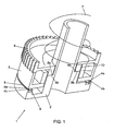
- Fig. 1 shows a mirror adjustment device 1 according to the invention.
- the mirror adjustment device 1 comprises a mirror foot 2 and a mirror housing 3 which is adjustably connected with the mirror foot 2.
- the mirror housing 3 can translate and rotate relative to the mirror foot 2.
- the mirror adjustment device 1 is usually mounted on a motor vehicle, for example as an outside mirror unit of a motor vehicle.
- the outside mirror unit of the motor vehicle usually comprises also a mirror cap that surrounds the mirror housing, and a mirror base that surrounds the mirror foot. Between the mirror cap and the mirror base there is usually a space, for example, to enable adjustment of the mirror cap relative to the mirror base.
- the mirror housing 3 is adjustable between a folded-in position in which the mirror housing 3 is situated substantially along the motor vehicle and a folded-out position in which the mirror housing 3 is situated substantially transversely to the motor vehicle. In adjusting the mirror housing 3, the mirror cap moves along with it.
- the mirror housing 3 is furthermore adjustable relative to the mirror foot 2 between a first position and a second position, where in the first position the distance between neighboring surfaces 4a, 4b of the mirror housing 3 and the mirror foot 2 is greater than the distance between the neighboring surfaces 4a, 4b of the mirror housing 3 and the mirror foot 2 in the second position.
- Fig. 1 it is shown that between neighboring surfaces 4a, 4b of the mirror housing 3 and the mirror foot 2, respectively, there is a slit 5.
- Fig. 2 the mirror housing 3 is shown in the second position, where the distance between the neighboring surfaces 4a and 4b is less than in the first position of Fig. 1 and the neighboring surfaces 4a and 4b substantially abut against each other. In the second position there is practically no slit between the mirror housing 3 and the mirror foot 2.
- the mirror housing 3 is adjustable relative to the mirror foot 2 between the first position and the second position in axial direction of the mirror foot 2.
- the mirror adjustment device 1 is provided with a drive gearwheel 6 of a drive unit, enabling driven adjustment of the mirror housing 3 between the folded-in position and the folded-out position.
- Bearing on the drive gearwheel 6 is usually a main spring 7, which presses the drive gearwheel 6 via the surfaces 8a, 8b onto the mirror foot 2.
- an elastic element 9 designed as a ring-shaped spring element.
- the ring-shaped spring 9 is designed to bias the mirror housing 3 towards the first position. In this exemplary embodiment, this means that the ring-shaped spring 9 tends to push the mirror housing 3 upwards.
- the elastic element 9 may also be designed as a spiral spring which, for example, may be mounted between the mirror housing 3 and the drive gearwheel 6 to bias the mirror housing 3 to the first position.
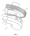
- a spring 9 of ring-shaped bent configuration is provided, as can be seen, for example, in Fig. 4 .
- the mirror adjustment device 1 is furthermore provided with cooperating elements 10 for bringing, under the influence of the ring-shaped spring 9, the mirror housing 3 in the first position when adjusting the mirror housing 3 between the folded-in position and the folded-out position.
- the cooperating elements 10 comprise in this exemplary embodiment the ring 11 and a run-on surface 12 on the drive gearwheel 6. Via the cooperating elements 10 and the ring-shaped spring 9 the mirror housing 3 can be adjusted between the first position and the second position independently of the main spring 7.
- the ring 11 is restrained from rotation with respect to the mirror foot 2, as shown in Fig. 4 . Via the rib 14 which engages in the groove 15, the ring 11 can only translate in axial direction of the mirror foot 2 and the ring 11 is thus rotation-locked with respect to the mirror foot 2.
- a run-on surface 16 of the ring 11 cooperates with the run-on surface 12 of the drive gearwheel 6.
- the force of the main spring 7 can be transferred via the drive gearwheel 6 and the ring 11 onto the mirror housing 3, so that the mirror housing 3 is pressed down, against the bias of the ring-shaped spring 9, until the neighboring surfaces 4a and 4b abut.
- the slit 5 will substantially disappear in the second position, as a result of which the generation of vibrations and/or noise, for example in the folded-out position of the mirror housing 3, can be reduced.
- the run-on surfaces 12 and 16 of the drive gearwheel 6 and the ring 11, respectively, do not cooperate and the ring 11 with the mirror housing 3 can be pushed upwards by the bias of the ring-shaped spring 9.
- the force of the main spring 7 is transferred along the surfaces 8a and 8b via the drive gearwheel 6 to the mirror foot 2, as a result of which the mirror housing 3 in the first position is free from the influence of the main spring 7.
- the force that the main spring 7 exerts on the drive gearwheel 6 remains unchanged.
- the mirror housing 3 can be brought into the first position or the second position.
- the mirror housing 3 In the first position the mirror housing 3 is pushed against the drive gearwheel 6 by the ring-shaped spring 9, so that during adjustment between the folded-in position and the folded-out position friction arises between the drive gearwheel 6 and the mirror housing 3. As a result, during adjustment, the mirror housing 3 becoming unstable or starting to vibrate or rattle can be prevented. By adjusting against the friction, a relatively stable adjustment of the mirror housing 3 can be achieved.
- the surfaces 8a and 8b of the drive gearwheel 6 and the mirror foot 2 respectively, move over each other up to the run-on surfaces 13a and 13b which indicate the end of the adjustment path.
- the mirror housing 3 is in the first position, with the ring-shaped spring 9 pushing the mirror housing 3 and the ring 11 upwards and a slit 5 being present between the mirror housing 3 and the mirror foot 2.
- the run-on surface 13a runs against run-on surface 13b
- the run-on surface 16 of the ring 11 runs against the run-on surface 12 of the drive gearwheel 6, so that the ring 11 is, as it were, pressed between the mirror housing 3 and the drive gearwheel 6.
- the mirror housing 3 is, as it were, automatically, through cooperation of the cooperating elements 10, in particular through cooperation of the run-on surfaces 11 and 16, brought from the first position to the second position, independently of the main spring 7.
- the invention is not limited to the exemplary embodiment represented here. Many variants are possible.
- the displacement of the mirror housing with respect to the mirror foot between the first and the second position may be carried out, for example, in transversal direction with respect to the mirror foot and/or in a combination of an axial and transversal direction.
- Such variants are understood to be within the scope of the invention as represented in the following claims.
Landscapes
- Engineering & Computer Science (AREA)
- Multimedia (AREA)
- Mechanical Engineering (AREA)
- Rear-View Mirror Devices That Are Mounted On The Exterior Of The Vehicle (AREA)
Description
- The invention relates to a mirror adjustment device, in particular for a motor vehicle, comprising a mirror foot for mounting on a motor vehicle and a mirror housing adjustably connected with the mirror foot, wherein the mirror housing is adjustable between a folded-in position in which the mirror housing is situated substantially along the motor vehicle and a folded-out position in which the mirror housing is situated substantially transversely to the motor vehicle. The mirror foot is usually surrounded by a mirror base and the mirror housing is usually surrounded by a mirror cap.
- Such a mirror adjustment device is generally known and is widely used in, for example, outside mirrors of motor vehicles. The mirror housing can thus be adjusted between the folded-in position, in which the mirror housing is situated substantially along the motor vehicle, for instance in a parking position of the vehicle, and a folded-out position, in which the mirror housing is situated substantially transversely to the motor vehicle and projects from the motor vehicle relatively far, for instance while the motor vehicle is being driven. Thus, damage to the outside mirror can be prevented. Since the mirror cap surrounds the mirror housing and the mirror base surrounds the mirror foot, during adjustment of the mirror housing relative to the mirror foot, also the mirror cap is adjusted relative to the mirror base. For the sake of manufacturing tolerances and/or to enable adjustment of the mirror cap relative to the mirror base, there is usually a space between the mirror cap and the mirror base. This space may be, for example, in the magnitude order of 0.5-1 mm. Disadvantages of such a space are that it can get soiled and/or that it can cause noise, for instance of wind rustling, during driving of the motor vehicle and/or that the mirror cap may start to vibrate or rattle with respect to the mirror base.
- To prevent these problems, it is known to provide the mirror adjustment device with, for example, a sealing to fill up the space between the mirror base and the mirror cap. The sealing may be, for example, a mat sealing having an open foam structure. However, such a sealing may get damaged, so that noise, soiling and/or vibrations can occur again.
- Publication
JP10-129349 - An object of the invention is to provide a mirror adjustment device that prevents at least one of the above-mentioned disadvantages. To this end, the invention provides a mirror adjustment device, in particular for a motor vehicle, comprising a mirror foot for mounting on a motor vehicle and a mirror housing adjustably connected with the mirror foot, wherein the mirror housing is adjustable between a folded-in position in which the mirror housing is situated substantially along the motor vehicle and a folded-out position in which the mirror housing is situated substantially transversely to the motor vehicle, wherein the mirror housing furthermore is adjustable between a first position and a second position, wherein in the first position the distance between neighboring surfaces of the mirror housing and the mirror foot is greater than the distance between the neighboring surfaces of the mirror housing and the mirror foot in the second position, wherein the mirror adjustment device furthermore comprises an elastic element for biasing the mirror housing towards the first position and wherein the mirror adjustment device is provided with cooperating elements for, under the influence of the elastic element, bringing the mirror housing into the first position when adjusting the mirror housing between the folded-in position and the folded-out position.
- As the distance between neighboring surfaces of the mirror housing and the mirror foot in the first position is greater than the distance between the neighboring surfaces of the mirror housing and the mirror foot in the second position, there is in the first position a slit between the neighboring surfaces of the mirror housing and the mirror foot. In the second position the distance between the neighboring surfaces of the mirror housing and the mirror foot is smaller and the slit can be substantially closed and/or the neighboring surfaces of the mirror housing and the mirror foot can substantially abut against each other.
- By the provision of an elastic element that biases the mirror housing towards the first position and cooperating elements with which the mirror housing can be brought into the first position, relatively simply the slit can be realized between the mirror housing and the mirror foot, so that adjustment between the folded-in position and the folded-out position can take place relatively smoothly.
- By furthermore designing the cooperating elements such that at the end of an adjustment path between the folded-in position and the folded-out position the mirror housing can be brought to the second position, in a relatively simple manner the distance between the neighboring surfaces of the mirror housing and the mirror foot can be reduced, so that the slit between the mirror housing and the mirror foot can, for example, be substantially closed in the folded-out position, so that accumulation of dirt, vibrating or noise can be reduced and/or obviated.
- By designing the mirror adjustment device according to the invention, the gap between the mirror cap and the mirror base will be greater during adjustment between the folded-in position and the folded-out position than when the mirror cap is in the folded-in position and/or the folded-out position. As a result, for example, damage to the mat sealing between the mirror cap and the mirror base during adjustment can be reduced.
- As the cooperating elements and/or the mirror housing in the first position are pressed against the drive gearwheel under the influence of the elastic element, friction can arise between the mirror housing and/or the cooperating elements and the drive gearwheel. By counter-friction adjustment of the mirror housing between the folded-in position and the folded-out position, vibrating or rattling of the mirror housing during adjustment can be obviated and in a relatively stable manner the mirror housing can be adjusted between the folded-in position and the folded-out position.
- As the cooperating elements comprise a ring being rotation-locked with the mirror foot, in a simple manner, via opposite sides of the ring a cooperation between the drive gearwheel on the one hand and the mirror housing on the other can be achieved. By providing the rotation-locked ring and the drive gearwheel with cooperating projections or run-on surfaces, in a simple manner rotation of the drive gearwheel with respect to the rotation-locked ring can be effected, for example, run-on surfaces of the ring can run on against run-on surfaces of the drive gearwheel so that, for example, energization of the mirror housing towards the first position or towards the second position can be achieved.
- The mirror adjustment device may be provided with a main spring which engages the drive gearwheel and presses the drive gearwheel onto the mirror foot. For example, the axial direction of the main spring coincides substantially with the axial direction of the mirror foot and the main spring presses on the mirror foot in axial direction. The mirror housing is usually situated in the space between the mirror foot and the drive gearwheel. Advantageously, the cooperating elements between the mirror housing and the drive gearwheel are so configured that in the first position the mirror housing is free from the influence of the main spring. In the first position the mirror housing only experiences the bias of the elastic element, so that a slit can form between the mirror housing and the mirror foot. Also, the elastic element can be made of relatively light design, because it only needs to energize the mirror housing and is independent of the main spring.
- By designing the cooperating elements such that in the second position the mirror housing is pressed against the mirror foot by the main spring against the bias of the elastic element, the mirror housing can be energized towards the second position independently of the main spring but determined solely by the configuration of cooperating elements and/or the cooperating projections and/or cooperating run-on surfaces. The force of the main spring can be transferred via the cooperating elements to the mirror housing and is sufficiently large to overcome the bias of the elastic element. Preferably, the mirror housing at the end of an adjustment path between folded-in position and folded-out position is energized towards the second position, for example in that a run-on surface of the rotation-locked ring runs against a run-on surface of the drive gearwheel and thus a coupling can be effected between the mirror housing and the drive gearwheel along which the force of the main spring can be transferred to the mirror housing.
- As the elastic element energizes the mirror housing independently of the main spring, the elastic element can be made of relatively light and inexpensive design. For example, the elastic element may be designed as an auxiliary spring, or as a ring-shaped spring element.
- By including the elastic element between the mirror foot and the mirror housing, the bias of the elastic element towards the mirror housing works opposite to the force of, for example, the main spring.
- Further advantageous embodiments are represented in the subclaims.
- The invention will be elucidated on the basis of an exemplary embodiment which is represented in a drawing. In the drawing:
-
Fig. 1 shows a perspective cross section of a mirror adjustment device according to the invention in the first position; -
Fig. 2 shows a perspective cross section of a mirror adjustment device according to the invention in the second position; -
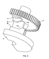
Fig. 3 shows an exploded perspective view of the drive gearwheel around the mirror foot of a mirror adjustment device according to the invention; and -
Fig. 4 shows an exploded perspective view of a mirror adjustment device according to the invention. - It is noted that the figures are only schematic representations of a preferred embodiment of the invention that is described by way of non-limiting exemplary embodiment. In the figures, equal or corresponding parts are represented with the same reference numerals. For the sake of simplicity, the mirror cap surrounding the mirror housing and the mirror base surrounding the mirror foot are not represented.
-
Fig. 1 shows a mirror adjustment device 1 according to the invention. The mirror adjustment device 1 comprises amirror foot 2 and amirror housing 3 which is adjustably connected with themirror foot 2. Themirror housing 3 can translate and rotate relative to themirror foot 2. Via themirror foot 2 the mirror adjustment device 1 is usually mounted on a motor vehicle, for example as an outside mirror unit of a motor vehicle. The outside mirror unit of the motor vehicle usually comprises also a mirror cap that surrounds the mirror housing, and a mirror base that surrounds the mirror foot. Between the mirror cap and the mirror base there is usually a space, for example, to enable adjustment of the mirror cap relative to the mirror base. - The
mirror housing 3 is adjustable between a folded-in position in which themirror housing 3 is situated substantially along the motor vehicle and a folded-out position in which themirror housing 3 is situated substantially transversely to the motor vehicle. In adjusting themirror housing 3, the mirror cap moves along with it. - The
mirror housing 3 is furthermore adjustable relative to themirror foot 2 between a first position and a second position, where in the first position the distance between neighboringsurfaces mirror housing 3 and themirror foot 2 is greater than the distance between the neighboringsurfaces mirror housing 3 and themirror foot 2 in the second position. - In
Fig. 1 it is shown that between neighboringsurfaces mirror housing 3 and themirror foot 2, respectively, there is aslit 5. InFig. 2 themirror housing 3 is shown in the second position, where the distance between the neighboringsurfaces Fig. 1 and the neighboringsurfaces mirror housing 3 and themirror foot 2. In this exemplary embodiment, themirror housing 3 is adjustable relative to themirror foot 2 between the first position and the second position in axial direction of themirror foot 2. - The mirror adjustment device 1 is provided with a
drive gearwheel 6 of a drive unit, enabling driven adjustment of themirror housing 3 between the folded-in position and the folded-out position. Bearing on thedrive gearwheel 6 is usually amain spring 7, which presses thedrive gearwheel 6 via thesurfaces mirror foot 2. - Situated between the
mirror housing 3 and themirror foot 2 in this exemplary embodiment is anelastic element 9 designed as a ring-shaped spring element. The ring-shaped spring 9 is designed to bias themirror housing 3 towards the first position. In this exemplary embodiment, this means that the ring-shapedspring 9 tends to push themirror housing 3 upwards. Possibly, theelastic element 9 may also be designed as a spiral spring which, for example, may be mounted between themirror housing 3 and thedrive gearwheel 6 to bias themirror housing 3 to the first position. Here, however, in a simple manner, aspring 9 of ring-shaped bent configuration is provided, as can be seen, for example, inFig. 4 . - The mirror adjustment device 1 is furthermore provided with cooperating
elements 10 for bringing, under the influence of the ring-shapedspring 9, themirror housing 3 in the first position when adjusting themirror housing 3 between the folded-in position and the folded-out position. The cooperatingelements 10 comprise in this exemplary embodiment thering 11 and a run-onsurface 12 on thedrive gearwheel 6. Via the cooperatingelements 10 and the ring-shapedspring 9 themirror housing 3 can be adjusted between the first position and the second position independently of themain spring 7. Thering 11 is restrained from rotation with respect to themirror foot 2, as shown inFig. 4 . Via therib 14 which engages in thegroove 15, thering 11 can only translate in axial direction of themirror foot 2 and thering 11 is thus rotation-locked with respect to themirror foot 2. - In the second position of the
mirror housing 3, a run-onsurface 16 of thering 11 cooperates with the run-onsurface 12 of thedrive gearwheel 6. As a result, the distance between thedrive gearwheel 6 and themirror housing 3 is enlarged, as a result of which thering 11 is, as it were, clamped between thedrive gearwheel 6 and themirror housing 3. The force of themain spring 7 can be transferred via thedrive gearwheel 6 and thering 11 onto themirror housing 3, so that themirror housing 3 is pressed down, against the bias of the ring-shapedspring 9, until the neighboringsurfaces surfaces slit 5 will substantially disappear in the second position, as a result of which the generation of vibrations and/or noise, for example in the folded-out position of themirror housing 3, can be reduced. - In the first position the run-on
surfaces drive gearwheel 6 and thering 11, respectively, do not cooperate and thering 11 with themirror housing 3 can be pushed upwards by the bias of the ring-shapedspring 9. The force of themain spring 7 is transferred along thesurfaces drive gearwheel 6 to themirror foot 2, as a result of which themirror housing 3 in the first position is free from the influence of themain spring 7. Both in the first position and in the second position, the force that themain spring 7 exerts on thedrive gearwheel 6 remains unchanged. Thus, independently of themain spring 7, by the cooperatingelements 10 and the ring-shapedspring 9, themirror housing 3 can be brought into the first position or the second position. - In the first position the
mirror housing 3 is pushed against thedrive gearwheel 6 by the ring-shapedspring 9, so that during adjustment between the folded-in position and the folded-out position friction arises between thedrive gearwheel 6 and themirror housing 3. As a result, during adjustment, themirror housing 3 becoming unstable or starting to vibrate or rattle can be prevented. By adjusting against the friction, a relatively stable adjustment of themirror housing 3 can be achieved. - When adjusting the
mirror housing 3 between the folded-in position and the folded-out position, thesurfaces drive gearwheel 6 and themirror foot 2, respectively, move over each other up to the run-onsurfaces mirror housing 3 is in the first position, with the ring-shapedspring 9 pushing themirror housing 3 and thering 11 upwards and aslit 5 being present between themirror housing 3 and themirror foot 2. When the run-onsurface 13a runs against run-onsurface 13b, also the run-onsurface 16 of thering 11 runs against the run-onsurface 12 of thedrive gearwheel 6, so that thering 11 is, as it were, pressed between themirror housing 3 and thedrive gearwheel 6. As a result, a coupling is effected between thedrive gearwheel 6 and themirror housing 3 along which the force of themain spring 7 can be transferred to themirror housing 3 to thereby press themirror housing 3 downwards, against the bias of thespring 9, towards the second position and substantially close theslit 5. At the end of the adjustment path between the folded-in position and the folded-out position, themirror housing 3 is, as it were, automatically, through cooperation of the cooperatingelements 10, in particular through cooperation of the run-onsurfaces main spring 7. - Upon reverse adjustment, the cooperation between the run-on
surfaces ring 11 and themirror housing 3 can be pushed upwards to the first position again by the ring-shapedspring 9. - The invention is not limited to the exemplary embodiment represented here. Many variants are possible. Thus, the displacement of the mirror housing with respect to the mirror foot between the first and the second position may be carried out, for example, in transversal direction with respect to the mirror foot and/or in a combination of an axial and transversal direction. Such variants are understood to be within the scope of the invention as represented in the following claims.
Claims (13)
- A mirror adjustment device, in particular for a motor vehicle, comprising a mirror foot (2) for mounting on a motor vehicle and a mirror housing (3) adjustably connected with the mirror foot (2), wherein the mirror housing (3) is adjustable between a folded-in position in which the mirror housing (3) is situated substantially along the motor vehicle and a folded-out position in which the mirror housing (3) is situated substantially transversely to the motor vehicle, wherein the mirror housing (3) furthermore is adjustable between a first position and a second position, wherein in the first position the distance between neighboring surfaces of the mirror housing (3) and the mirror foot (2) is greater than the distance between the neighboring surfaces of the mirror housing (3) and the mirror foot (2) in the second position, wherein the mirror adjustment device furthermore comprises an elastic element (9) for biasing the mirror housing (3) towards the first position and wherein the mirror adjustment device is provided with cooperating elements (10, 12, 16) for, under the influence of the elastic element (9), bringing the mirror housing (3) into the first position when adjusting the mirror housing (3) between the folded-in position and the folded-out position, characterized in that the cooperating elements (10) comprise run-on surfaces (12, 16) on a drive gearwheel (6) and a ring (11) respectively, which do not cooperate in the first position such that the ring (11) with the mirror housing (3) can be pushed upwards by the bias of the elastic element (9).
- A mirror adjustment device according to claim 1, wherein the cooperating elements (10, 12, 16) are designed to bring the mirror housing (3) at the end of an adjustment path between the folded-in position and the folded out position to the second position.
- A mirror adjustment device according to claim 1 or 2, wherein the cooperating elements (10, 12, 16) are designed for cooperation between the mirror housing (3) and a drive gearwheel (6) of a drive unit for adjusting the mirror housing (3) between the folded-in position and the folded-out position.
- A mirror adjustment device according to claim 3, wherein the cooperating elements (10, 12, 16) and/or the mirror housing (3) in the first position are pressed against the drive gearwheel (6) under the influence of the elastic element (9).
- A mirror adjustment device according to claim 3 or 4, wherein the cooperating elements (10, 12, 16) comprise a ring (11) being rotation-locked with the mirror foot (2), which is provided with opposite sides for cooperation with the drive gearwheel (6) on one side and the mirror housing (3) on the other side.
- A mirror adjustment device according to claim 5, wherein the rotation locked ring (11) and the drive gearwheel (6) are provided with the cooperating projections and/or run-on surfaces (12,16).
- A mirror adjustment device according to any one of the preceding claims, furthermore comprising a main spring (7) for pressing the drive gearwheel (6) onto the mirror foot (2).
- A mirror adjustment device according to claim 7, wherein the mirror housing (3) in the first position is free from the influence of the main spring (7).
- A mirror adjustment device according to claim 7 or 8, wherein the neighboring surfaces of the mirror housing (3) and the mirror foot (2) in the second position are pressed against each other under the influence of the main spring (7), against the bias of the elastic element (9).
- A mirror adjustment device according to any one of the preceding claims, wherein the elastic element is an auxiliary spring (9).
- A mirror adjustment device according to any one of the preceding claims, wherein the elastic element (9) is receivable between the mirror foot (2) and the mirror housing (3).
- A mirror adjustment device according to any one of the preceding claims, wherein the elastic element (9) is a ring-shaped spring element.
- A mirror adjustment device according to any one of the preceding claims, wherein the mirror housing (3) is adjustable between the first position and the second position in axial direction of the mirror foot (2).
Applications Claiming Priority (2)
| Application Number | Priority Date | Filing Date | Title |
|---|---|---|---|
| NL2003061A NL2003061C2 (en) | 2009-06-22 | 2009-06-22 | MIRROR ADJUSTMENT. |
| PCT/NL2010/050383 WO2010151120A1 (en) | 2009-06-22 | 2010-06-22 | Mirror adjustment device |
Publications (2)
| Publication Number | Publication Date |
|---|---|
| EP2445755A1 EP2445755A1 (en) | 2012-05-02 |
| EP2445755B1 true EP2445755B1 (en) | 2014-04-23 |
Family
ID=41600379
Family Applications (1)
| Application Number | Title | Priority Date | Filing Date |
|---|---|---|---|
| EP10728420.0A Active EP2445755B1 (en) | 2009-06-22 | 2010-06-22 | Mirror adjustment device |
Country Status (7)
| Country | Link |
|---|---|
| US (1) | US8955992B2 (en) |
| EP (1) | EP2445755B1 (en) |
| JP (1) | JP5770722B2 (en) |
| KR (1) | KR101676895B1 (en) |
| CN (1) | CN102458924B (en) |
| NL (1) | NL2003061C2 (en) |
| WO (1) | WO2010151120A1 (en) |
Families Citing this family (12)
| Publication number | Priority date | Publication date | Assignee | Title |
|---|---|---|---|---|
| NL2009160C2 (en) | 2012-07-09 | 2014-01-13 | Mci Mirror Controls Int Nl Bv | ADJUSTMENT INSTRUMENT. |
| CN104175961B (en) | 2013-05-23 | 2018-08-07 | 菲克米罗尔斯股份公司 | Foldable rear-view mirror for motor vehicle |
| EP2902263B1 (en) | 2014-02-04 | 2018-04-11 | Fico Mirrors France S.A.S. | Rear view mirror assembly for motor vehicles |
| NL2012333B1 (en) | 2014-02-28 | 2015-10-19 | MCI (Mirror Controls International) Netherlands B V | Mirror adjustment mechanism, in particular for a wing mirror for a motor vehicle. |
| NL2013508B1 (en) | 2014-09-22 | 2016-09-29 | MCI (Mirror Controls International) Netherlands B V | Adjustment instrument, Outside mirror unit, Motor vehicle. |
| NL2015676B1 (en) * | 2015-10-28 | 2017-05-29 | MCI (Mirror Controls International) Netherlands B V | Adjustment instrument for an outside view unit for a vehicle. |
| US20190275943A1 (en) | 2018-03-08 | 2019-09-12 | Magna Mirrors Holding Gmbh | Exterior mirror assembly for a motor vehicle |
| CN108583441A (en) * | 2018-04-28 | 2018-09-28 | 宁波新华泰模塑电器有限公司 | A kind of rear-vision mirror face adjuster and its adjusting method |
| DE102019207010B4 (en) | 2018-06-06 | 2022-03-24 | Magna Mirrors Holding Gmbh | EXTERIOR REARVIEW MIRROR ASSEMBLY FOR A VEHICLE |
| US10940801B1 (en) | 2019-09-09 | 2021-03-09 | Motherson Innovations Company Limited | Actuating device for a component |
| NL2025061B1 (en) * | 2020-03-05 | 2021-10-14 | Mci Mirror Controls Int Netherlands B V | Adjustment device, and method for assembling |
| NL2025272B1 (en) * | 2020-04-03 | 2021-10-25 | Mci Mirror Controls Int Netherlands B V | Adjusting instrument for an exterior vision unit of a motor vehicle |
Family Cites Families (9)
| Publication number | Priority date | Publication date | Assignee | Title |
|---|---|---|---|---|
| JPH10129349A (en) * | 1996-11-06 | 1998-05-19 | Molten Corp | Motor-driven containing type door mirror |
| JP3795194B2 (en) * | 1997-08-20 | 2006-07-12 | 株式会社東海理化電機製作所 | Door mirror electric storage device |
| DE10006913B4 (en) * | 2000-02-16 | 2005-12-22 | Bühler Motor GmbH | Exterior rearview mirror for a motor vehicle |
| NL1016915C2 (en) * | 2000-12-19 | 2002-06-21 | Iku Holding Montfoort Bv | Hinge actuator. |
| JP2002293190A (en) * | 2001-03-30 | 2002-10-09 | Ishizaki Honten:Kk | Vehicle side mirror |
| JPWO2003033303A1 (en) * | 2001-10-11 | 2005-02-03 | 株式会社村上開明堂 | Vehicle rearview mirror |
| NL1023227C2 (en) * | 2003-04-18 | 2004-10-19 | Iku Holding Montfoort Bv | Exterior mirror unit. |
| TWI232187B (en) * | 2003-06-28 | 2005-05-11 | Chaw Khong Co Ltd | Electrical operable pivoting back-mirror device |
| JP2009113753A (en) * | 2007-11-09 | 2009-05-28 | Honda Motor Co Ltd | External mirror structure for vehicles |
-
2009
- 2009-06-22 NL NL2003061A patent/NL2003061C2/en not_active IP Right Cessation
-
2010
- 2010-06-22 JP JP2012517426A patent/JP5770722B2/en active Active
- 2010-06-22 EP EP10728420.0A patent/EP2445755B1/en active Active
- 2010-06-22 CN CN201080035493.2A patent/CN102458924B/en active Active
- 2010-06-22 KR KR1020127001698A patent/KR101676895B1/en active Active
- 2010-06-22 US US13/379,874 patent/US8955992B2/en active Active
- 2010-06-22 WO PCT/NL2010/050383 patent/WO2010151120A1/en not_active Ceased
Also Published As
| Publication number | Publication date |
|---|---|
| KR20120083268A (en) | 2012-07-25 |
| EP2445755A1 (en) | 2012-05-02 |
| US20120162796A1 (en) | 2012-06-28 |
| WO2010151120A1 (en) | 2010-12-29 |
| CN102458924B (en) | 2016-01-20 |
| JP5770722B2 (en) | 2015-08-26 |
| US8955992B2 (en) | 2015-02-17 |
| JP2012530651A (en) | 2012-12-06 |
| CN102458924A (en) | 2012-05-16 |
| NL2003061C2 (en) | 2010-12-23 |
| KR101676895B1 (en) | 2016-11-16 |
Similar Documents
| Publication | Publication Date | Title |
|---|---|---|
| US8955992B2 (en) | Mirror adjustment device | |
| EP1445150B1 (en) | Motorized retracting unit and motorized retractable rearview mirror | |
| KR20110073328A (en) | Head-up display device | |
| JP2006511385A (en) | Drive device for vehicle seat adjuster having slide member | |
| CN110154903B (en) | Connector device for a motor vehicle rear-view mirror | |
| KR20230075461A (en) | Actuators for folding and adjusting | |
| EP2212155B1 (en) | Mounting construction for an outside mirror unit | |
| JP2002520209A (en) | Steering wheel with driver airbag module | |
| JP6817872B2 (en) | Mounting structure of airbag device | |
| EP3052342B1 (en) | Mirror adjustment device with play suppression | |
| EP2780198B1 (en) | Motor vehicle steering column trim element | |
| JP5686959B2 (en) | Mirror device for vehicle | |
| JP6510385B2 (en) | Automotive rearview mirror assembly | |
| JP7172162B2 (en) | Electric storage unit for vehicle outside mirror device, vehicle outside mirror device | |
| KR101598718B1 (en) | Slide device of vehicle seat | |
| US7412743B2 (en) | Wiper for an automobile rear-view mirror | |
| JP2008238977A (en) | Inner mirror device | |
| KR100764154B1 (en) | Telescopic Device for Vehicle Steering Column | |
| KR102205602B1 (en) | Positioning Pin for Serration Bar Jointed Seat Motor of Car | |
| JP2004503421A5 (en) | ||
| CN108626361B (en) | Transmission housing and transmission drive unit | |
| KR20180048113A (en) | Reducer for vehicle | |
| JPS6037857Y2 (en) | Automotive outside mirror | |
| CN110785322A (en) | Holding device for holding a vehicle part on a motor vehicle glazing | |
| JP2013237374A (en) | Door mirror for vehicle |
Legal Events
| Date | Code | Title | Description |
|---|---|---|---|
| PUAI | Public reference made under article 153(3) epc to a published international application that has entered the european phase |
Free format text: ORIGINAL CODE: 0009012 |
|
| 17P | Request for examination filed |
Effective date: 20120102 |
|
| AK | Designated contracting states |
Kind code of ref document: A1 Designated state(s): AL AT BE BG CH CY CZ DE DK EE ES FI FR GB GR HR HU IE IS IT LI LT LU LV MC MK MT NL NO PL PT RO SE SI SK SM TR |
|
| DAX | Request for extension of the european patent (deleted) | ||
| RAP1 | Party data changed (applicant data changed or rights of an application transferred) |
Owner name: NIBC BANK N.V. |
|
| RAP1 | Party data changed (applicant data changed or rights of an application transferred) |
Owner name: MCI (MIRROR CONTROLS INTERNATIONAL) NETHERLANDS B. |
|
| 111Z | Information provided on other rights and legal means of execution |
Free format text: AL AT BE BG CH CY CZ DE DK EE ES FI FR GB GR HR HU IE IS IT LT LU LV MC MK MT NL NO PL PT RO SE SI SK SM TR Effective date: 20121203 |
|
| GRAP | Despatch of communication of intention to grant a patent |
Free format text: ORIGINAL CODE: EPIDOSNIGR1 |
|
| INTG | Intention to grant announced |
Effective date: 20131202 |
|
| GRAS | Grant fee paid |
Free format text: ORIGINAL CODE: EPIDOSNIGR3 |
|
| GRAA | (expected) grant |
Free format text: ORIGINAL CODE: 0009210 |
|
| AK | Designated contracting states |
Kind code of ref document: B1 Designated state(s): AL AT BE BG CH CY CZ DE DK EE ES FI FR GB GR HR HU IE IS IT LI LT LU LV MC MK MT NL NO PL PT RO SE SI SK SM TR |
|
| REG | Reference to a national code |
Ref country code: GB Ref legal event code: FG4D |
|
| REG | Reference to a national code |
Ref country code: CH Ref legal event code: EP |
|
| REG | Reference to a national code |
Ref country code: AT Ref legal event code: REF Ref document number: 663621 Country of ref document: AT Kind code of ref document: T Effective date: 20140515 |
|
| REG | Reference to a national code |
Ref country code: IE Ref legal event code: FG4D |
|
| REG | Reference to a national code |
Ref country code: DE Ref legal event code: R096 Ref document number: 602010015394 Country of ref document: DE Effective date: 20140528 |
|
| REG | Reference to a national code |
Ref country code: AT Ref legal event code: MK05 Ref document number: 663621 Country of ref document: AT Kind code of ref document: T Effective date: 20140423 |
|
| REG | Reference to a national code |
Ref country code: NL Ref legal event code: VDEP Effective date: 20140423 |
|
| REG | Reference to a national code |
Ref country code: LT Ref legal event code: MG4D |
|
| PG25 | Lapsed in a contracting state [announced via postgrant information from national office to epo] |
Ref country code: FI Free format text: LAPSE BECAUSE OF FAILURE TO SUBMIT A TRANSLATION OF THE DESCRIPTION OR TO PAY THE FEE WITHIN THE PRESCRIBED TIME-LIMIT Effective date: 20140423 Ref country code: NL Free format text: LAPSE BECAUSE OF FAILURE TO SUBMIT A TRANSLATION OF THE DESCRIPTION OR TO PAY THE FEE WITHIN THE PRESCRIBED TIME-LIMIT Effective date: 20140423 Ref country code: LT Free format text: LAPSE BECAUSE OF FAILURE TO SUBMIT A TRANSLATION OF THE DESCRIPTION OR TO PAY THE FEE WITHIN THE PRESCRIBED TIME-LIMIT Effective date: 20140423 Ref country code: IS Free format text: LAPSE BECAUSE OF FAILURE TO SUBMIT A TRANSLATION OF THE DESCRIPTION OR TO PAY THE FEE WITHIN THE PRESCRIBED TIME-LIMIT Effective date: 20140823 Ref country code: BG Free format text: LAPSE BECAUSE OF FAILURE TO SUBMIT A TRANSLATION OF THE DESCRIPTION OR TO PAY THE FEE WITHIN THE PRESCRIBED TIME-LIMIT Effective date: 20140723 Ref country code: CY Free format text: LAPSE BECAUSE OF FAILURE TO SUBMIT A TRANSLATION OF THE DESCRIPTION OR TO PAY THE FEE WITHIN THE PRESCRIBED TIME-LIMIT Effective date: 20140423 Ref country code: NO Free format text: LAPSE BECAUSE OF FAILURE TO SUBMIT A TRANSLATION OF THE DESCRIPTION OR TO PAY THE FEE WITHIN THE PRESCRIBED TIME-LIMIT Effective date: 20140723 Ref country code: GR Free format text: LAPSE BECAUSE OF FAILURE TO SUBMIT A TRANSLATION OF THE DESCRIPTION OR TO PAY THE FEE WITHIN THE PRESCRIBED TIME-LIMIT Effective date: 20140724 |
|
| PG25 | Lapsed in a contracting state [announced via postgrant information from national office to epo] |
Ref country code: HR Free format text: LAPSE BECAUSE OF FAILURE TO SUBMIT A TRANSLATION OF THE DESCRIPTION OR TO PAY THE FEE WITHIN THE PRESCRIBED TIME-LIMIT Effective date: 20140423 Ref country code: PL Free format text: LAPSE BECAUSE OF FAILURE TO SUBMIT A TRANSLATION OF THE DESCRIPTION OR TO PAY THE FEE WITHIN THE PRESCRIBED TIME-LIMIT Effective date: 20140423 Ref country code: AT Free format text: LAPSE BECAUSE OF FAILURE TO SUBMIT A TRANSLATION OF THE DESCRIPTION OR TO PAY THE FEE WITHIN THE PRESCRIBED TIME-LIMIT Effective date: 20140423 Ref country code: ES Free format text: LAPSE BECAUSE OF FAILURE TO SUBMIT A TRANSLATION OF THE DESCRIPTION OR TO PAY THE FEE WITHIN THE PRESCRIBED TIME-LIMIT Effective date: 20140423 Ref country code: LV Free format text: LAPSE BECAUSE OF FAILURE TO SUBMIT A TRANSLATION OF THE DESCRIPTION OR TO PAY THE FEE WITHIN THE PRESCRIBED TIME-LIMIT Effective date: 20140423 Ref country code: SE Free format text: LAPSE BECAUSE OF FAILURE TO SUBMIT A TRANSLATION OF THE DESCRIPTION OR TO PAY THE FEE WITHIN THE PRESCRIBED TIME-LIMIT Effective date: 20140423 |
|
| PG25 | Lapsed in a contracting state [announced via postgrant information from national office to epo] |
Ref country code: PT Free format text: LAPSE BECAUSE OF FAILURE TO SUBMIT A TRANSLATION OF THE DESCRIPTION OR TO PAY THE FEE WITHIN THE PRESCRIBED TIME-LIMIT Effective date: 20140825 |
|
| REG | Reference to a national code |
Ref country code: DE Ref legal event code: R097 Ref document number: 602010015394 Country of ref document: DE |
|
| PG25 | Lapsed in a contracting state [announced via postgrant information from national office to epo] |
Ref country code: SK Free format text: LAPSE BECAUSE OF FAILURE TO SUBMIT A TRANSLATION OF THE DESCRIPTION OR TO PAY THE FEE WITHIN THE PRESCRIBED TIME-LIMIT Effective date: 20140423 Ref country code: EE Free format text: LAPSE BECAUSE OF FAILURE TO SUBMIT A TRANSLATION OF THE DESCRIPTION OR TO PAY THE FEE WITHIN THE PRESCRIBED TIME-LIMIT Effective date: 20140423 Ref country code: BE Free format text: LAPSE BECAUSE OF FAILURE TO SUBMIT A TRANSLATION OF THE DESCRIPTION OR TO PAY THE FEE WITHIN THE PRESCRIBED TIME-LIMIT Effective date: 20140423 Ref country code: MC Free format text: LAPSE BECAUSE OF FAILURE TO SUBMIT A TRANSLATION OF THE DESCRIPTION OR TO PAY THE FEE WITHIN THE PRESCRIBED TIME-LIMIT Effective date: 20140423 Ref country code: LU Free format text: LAPSE BECAUSE OF FAILURE TO SUBMIT A TRANSLATION OF THE DESCRIPTION OR TO PAY THE FEE WITHIN THE PRESCRIBED TIME-LIMIT Effective date: 20140622 Ref country code: DK Free format text: LAPSE BECAUSE OF FAILURE TO SUBMIT A TRANSLATION OF THE DESCRIPTION OR TO PAY THE FEE WITHIN THE PRESCRIBED TIME-LIMIT Effective date: 20140423 Ref country code: CZ Free format text: LAPSE BECAUSE OF FAILURE TO SUBMIT A TRANSLATION OF THE DESCRIPTION OR TO PAY THE FEE WITHIN THE PRESCRIBED TIME-LIMIT Effective date: 20140423 Ref country code: RO Free format text: LAPSE BECAUSE OF FAILURE TO SUBMIT A TRANSLATION OF THE DESCRIPTION OR TO PAY THE FEE WITHIN THE PRESCRIBED TIME-LIMIT Effective date: 20140423 |
|
| REG | Reference to a national code |
Ref country code: CH Ref legal event code: PL |
|
| PLBE | No opposition filed within time limit |
Free format text: ORIGINAL CODE: 0009261 |
|
| STAA | Information on the status of an ep patent application or granted ep patent |
Free format text: STATUS: NO OPPOSITION FILED WITHIN TIME LIMIT |
|
| REG | Reference to a national code |
Ref country code: IE Ref legal event code: MM4A |
|
| PG25 | Lapsed in a contracting state [announced via postgrant information from national office to epo] |
Ref country code: IT Free format text: LAPSE BECAUSE OF FAILURE TO SUBMIT A TRANSLATION OF THE DESCRIPTION OR TO PAY THE FEE WITHIN THE PRESCRIBED TIME-LIMIT Effective date: 20140423 |
|
| 26N | No opposition filed |
Effective date: 20150126 |
|
| REG | Reference to a national code |
Ref country code: GB Ref legal event code: 732E Free format text: REGISTERED BETWEEN 20150305 AND 20150311 |
|
| PG25 | Lapsed in a contracting state [announced via postgrant information from national office to epo] |
Ref country code: IE Free format text: LAPSE BECAUSE OF NON-PAYMENT OF DUE FEES Effective date: 20140622 Ref country code: LI Free format text: LAPSE BECAUSE OF NON-PAYMENT OF DUE FEES Effective date: 20140630 Ref country code: CH Free format text: LAPSE BECAUSE OF NON-PAYMENT OF DUE FEES Effective date: 20140630 |
|
| REG | Reference to a national code |
Ref country code: DE Ref legal event code: R097 Ref document number: 602010015394 Country of ref document: DE Effective date: 20150126 |
|
| REG | Reference to a national code |
Ref country code: FR Ref legal event code: GC Effective date: 20150403 |
|
| PG25 | Lapsed in a contracting state [announced via postgrant information from national office to epo] |
Ref country code: SI Free format text: LAPSE BECAUSE OF FAILURE TO SUBMIT A TRANSLATION OF THE DESCRIPTION OR TO PAY THE FEE WITHIN THE PRESCRIBED TIME-LIMIT Effective date: 20140423 |
|
| PG25 | Lapsed in a contracting state [announced via postgrant information from national office to epo] |
Ref country code: MT Free format text: LAPSE BECAUSE OF FAILURE TO SUBMIT A TRANSLATION OF THE DESCRIPTION OR TO PAY THE FEE WITHIN THE PRESCRIBED TIME-LIMIT Effective date: 20140423 |
|
| PG25 | Lapsed in a contracting state [announced via postgrant information from national office to epo] |
Ref country code: SM Free format text: LAPSE BECAUSE OF FAILURE TO SUBMIT A TRANSLATION OF THE DESCRIPTION OR TO PAY THE FEE WITHIN THE PRESCRIBED TIME-LIMIT Effective date: 20140423 |
|
| REG | Reference to a national code |
Ref country code: FR Ref legal event code: PLFP Year of fee payment: 7 |
|
| PG25 | Lapsed in a contracting state [announced via postgrant information from national office to epo] |
Ref country code: HU Free format text: LAPSE BECAUSE OF FAILURE TO SUBMIT A TRANSLATION OF THE DESCRIPTION OR TO PAY THE FEE WITHIN THE PRESCRIBED TIME-LIMIT; INVALID AB INITIO Effective date: 20100622 Ref country code: TR Free format text: LAPSE BECAUSE OF FAILURE TO SUBMIT A TRANSLATION OF THE DESCRIPTION OR TO PAY THE FEE WITHIN THE PRESCRIBED TIME-LIMIT Effective date: 20140423 |
|
| REG | Reference to a national code |
Ref country code: FR Ref legal event code: PLFP Year of fee payment: 8 |
|
| REG | Reference to a national code |
Ref country code: FR Ref legal event code: RG Effective date: 20171221 |
|
| REG | Reference to a national code |
Ref country code: FR Ref legal event code: PLFP Year of fee payment: 9 |
|
| PG25 | Lapsed in a contracting state [announced via postgrant information from national office to epo] |
Ref country code: MK Free format text: LAPSE BECAUSE OF FAILURE TO SUBMIT A TRANSLATION OF THE DESCRIPTION OR TO PAY THE FEE WITHIN THE PRESCRIBED TIME-LIMIT Effective date: 20140423 |
|
| PG25 | Lapsed in a contracting state [announced via postgrant information from national office to epo] |
Ref country code: AL Free format text: LAPSE BECAUSE OF FAILURE TO SUBMIT A TRANSLATION OF THE DESCRIPTION OR TO PAY THE FEE WITHIN THE PRESCRIBED TIME-LIMIT Effective date: 20140423 |
|
| P01 | Opt-out of the competence of the unified patent court (upc) registered |
Effective date: 20230516 |
|
| PGFP | Annual fee paid to national office [announced via postgrant information from national office to epo] |
Ref country code: FR Payment date: 20230627 Year of fee payment: 14 |
|
| PGFP | Annual fee paid to national office [announced via postgrant information from national office to epo] |
Ref country code: GB Payment date: 20230622 Year of fee payment: 14 |
|
| GBPC | Gb: european patent ceased through non-payment of renewal fee |
Effective date: 20240622 |
|
| PG25 | Lapsed in a contracting state [announced via postgrant information from national office to epo] |
Ref country code: FR Free format text: LAPSE BECAUSE OF NON-PAYMENT OF DUE FEES Effective date: 20240630 |
|
| PG25 | Lapsed in a contracting state [announced via postgrant information from national office to epo] |
Ref country code: GB Free format text: LAPSE BECAUSE OF NON-PAYMENT OF DUE FEES Effective date: 20240622 |
|
| PGFP | Annual fee paid to national office [announced via postgrant information from national office to epo] |
Ref country code: DE Payment date: 20250618 Year of fee payment: 16 |