EP2445313A1 - Microwave oven cavity and microwave oven - Google Patents
Microwave oven cavity and microwave oven Download PDFInfo
- Publication number
- EP2445313A1 EP2445313A1 EP10013871A EP10013871A EP2445313A1 EP 2445313 A1 EP2445313 A1 EP 2445313A1 EP 10013871 A EP10013871 A EP 10013871A EP 10013871 A EP10013871 A EP 10013871A EP 2445313 A1 EP2445313 A1 EP 2445313A1
- Authority
- EP
- European Patent Office
- Prior art keywords
- reflective element
- microwave oven
- microwave
- cavity
- fresnel reflective
- Prior art date
- Legal status (The legal status is an assumption and is not a legal conclusion. Google has not performed a legal analysis and makes no representation as to the accuracy of the status listed.)
- Granted
Links
- 239000011521 glass Substances 0.000 claims description 3
- 239000004033 plastic Substances 0.000 claims description 3
- 229920003023 plastic Polymers 0.000 claims description 3
- 238000010438 heat treatment Methods 0.000 abstract description 30
- 230000005684 electric field Effects 0.000 description 4
- 230000008878 coupling Effects 0.000 description 3
- 238000010168 coupling process Methods 0.000 description 3
- 238000005859 coupling reaction Methods 0.000 description 3
- 230000000694 effects Effects 0.000 description 2
- 230000005672 electromagnetic field Effects 0.000 description 2
- 238000000034 method Methods 0.000 description 2
- 230000005855 radiation Effects 0.000 description 2
- 238000004364 calculation method Methods 0.000 description 1
- 238000004140 cleaning Methods 0.000 description 1
- 230000001419 dependent effect Effects 0.000 description 1
- 239000000428 dust Substances 0.000 description 1
- 230000002349 favourable effect Effects 0.000 description 1
- 238000003780 insertion Methods 0.000 description 1
- 230000037431 insertion Effects 0.000 description 1
- 238000002310 reflectometry Methods 0.000 description 1
- 230000000717 retained effect Effects 0.000 description 1
- 239000002689 soil Substances 0.000 description 1
- 238000001228 spectrum Methods 0.000 description 1
- 239000000758 substrate Substances 0.000 description 1
- 239000012780 transparent material Substances 0.000 description 1
Images




Classifications
-
- H—ELECTRICITY
- H05—ELECTRIC TECHNIQUES NOT OTHERWISE PROVIDED FOR
- H05B—ELECTRIC HEATING; ELECTRIC LIGHT SOURCES NOT OTHERWISE PROVIDED FOR; CIRCUIT ARRANGEMENTS FOR ELECTRIC LIGHT SOURCES, IN GENERAL
- H05B6/00—Heating by electric, magnetic or electromagnetic fields
- H05B6/64—Heating using microwaves
- H05B6/6402—Aspects relating to the microwave cavity
-
- H—ELECTRICITY
- H05—ELECTRIC TECHNIQUES NOT OTHERWISE PROVIDED FOR
- H05B—ELECTRIC HEATING; ELECTRIC LIGHT SOURCES NOT OTHERWISE PROVIDED FOR; CIRCUIT ARRANGEMENTS FOR ELECTRIC LIGHT SOURCES, IN GENERAL
- H05B6/00—Heating by electric, magnetic or electromagnetic fields
- H05B6/64—Heating using microwaves
- H05B6/74—Mode transformers or mode stirrers
Definitions
- the present application is directed to a microwave oven cavity and a microwave oven comprising such a cavity.
- Microwave oven cavities usually are adapted to heat specific loads in a microwave electric field generated by coupling electromagnetic waves, i. e. microwaves, into the microwave cavity.
- the value of the microwave power absorbed in the unit volume of the load to be heated is a function of several parameters as well as the generator's frequency, electric permittivity, the dielectric loss of the complex impedance loads or strength of the electric field inside the load. The last one is most significant and responsible for variations of temperature within the load.
- microwave applicators are providing at least one of the following methods:
- a microwave oven cavity in which at least one inner wall comprises at least one Fresnel reflective element.
- a Fresnel reflective element is adapted to reflect microwaves coupled from a microwave source into the cavity in a predetermined manner.
- the Fresnel reflective element may comprise several Fresnel zones, comparable to a Fresnel lens in optics. Reflection of the microwaves within the cavity is modified by the at least one Fresnel reflective element such that hot and/or cold spots in a load, which may be a food item for example, can be prevented. Hence, uniform heating and excellent heating efficiency can be obtained.
- the invention is in particular based on the finding, that one relevant factor for obtaining uniform heating is to ensure a correct path of microwaves within the microwave cavity.
- a correct or adequate path of microwaves inter alia depends on the inner geometry of the cavity, the wavelength or range of wavelengths of the microwave source and propagation modes of the electromagnetic field within the cavity.
- the microwave source which may be a microwave feeder, i. e. the location where microwaves are coupled into the cavity plays a major role with respect to heating uniformity and heating efficiency.
- the present invention proposes to use Fresnel reflective elements provided with the inner walls of the microwave oven cavity.
- Inner walls of a microwave oven cavity comprising one or several Fresnel reflective elements, in particular inner walls nearly completely covered or provided with Fresnel reflective elements, can be designated as Fresnel reflective walls.
- the Fresnel reflective elements can be considered to represent inverse Fresnel lenses, which are well known in optics.
- a Fresnel reflective element can comprise at least one facet, preferably of linear type.
- linear type shall mean that the facet runs in parallel and along a lateral or longitudinal direction of an inner wall, preferably a side wall of the cavity. Such a linear type facet can be thought to implement a reflective parallel strip having a certain geometry and reflectivity. Facets may be provided with an inner wall in a transversal or longitudinal direction thereof.
- the term of linear type shall in particular point out, that the facet is linear in at least one of its dimensions. If a Fresnel reflective element comprises several facets that are arranged side by side, and the geometry of the facets is adapted accordingly, a linear Fresnel reflector is obtained.
- Such a linear Fresnel reflector may reflect microwaves into parallel columnar volume elements of the cavity, but also may focus microwaves impinging on the Fresnel reflector to a given area within the cavity, preferably an area in which a load is placed or located.
- Fresnel reflective elements or Fresnel reflective walls will lead to enhanced uniform heating and excellent heating efficiency.
- three vertical walls of a conventional microwave cavity of a microwave oven can be Fresnel reflective walls.
- Each Fresnel reflective wall may have a different target area within the cavity, and may cover the active area within the microwave oven cavity not only with respect to the surface, but also with respect to the volume of a load.
- An aperture of the at least one Fresnel reflective element may be at least partially of circular, ellipsoidal, hyperbolic or parabolic shape.
- the shape of the aperture of Fresnel reflective elements making up a Fresnel reflector may be selected according to shape and dimension of the microwave cavity and other relevant parameters. For example, a circular shape may be used with a square active area of the microwave cavity, and an elliptic shape may be used with a rectangular active area.
- At least one side wall preferably three side walls of the cavity, comprises at least one Fresnel reflective element having facets of linear type. It is preferred that the facets of such a linear Fresnel reflector run in a direction from a bottom to a top wall of the cavity.
- the position and orientation of the facets may depend on the position of the microwave source, or the microwave feeder, relative to the cavity, Facets running from bottom to top, or vice versa, can in particular be used for microwave sources or feeders arranged in or at the top or upper wall of the cavity.
- the Fresnel reflective elements running between opposite walls of the cavity may extend over nearly the whole distance between respective walls, such as their lateral or longitudinal dimensions. In this case, excellent heating characteristics can be obtained. However, it is also possible that at least one Fresnel reflective element or facet thereof extends only over a section of respective wall dimensions. In the case that the Fresnel reflective elements extend between the bottom and top wall of the cavity, the longitudinal dimension of respective Fresnel reflective elements of facets preferably is equal to about the distance between the bottom and top wall. Here, a maximum of microwave energy can be applied to the load.
- the at least one Fresnel reflective element is adapted to reflect at least microwaves of a given range of wavelengths, and wherein a width of the at least one Fresnel reflective element, preferably of each facet, at right angle to its longitudinal direction is greater than half of the center wavelength of the range of wavelengths.
- range of wavelengths shall in particular account for the fact that even "monochromatic" microwave sources generally emit a spectrum of microwave wavelengths. If a microwave source is used that in principle generates only one single wavelength, this single wavelength will correspond to the center wavelength. This situation applies to most microwave ovens which use magnetrons of given frequencies, such as 2.45 GHz and others.
- the width is preferably in the range from 65 mm to 85 mm.
- the depth of a Fresnel reflective element, preferably of each facet, at right angle both to the longitudinal direction thereof and to the inner wall is one quarter of the center wavelength of the range of wavelengths at the most.
- the microwave source is of 2.45 GHz type, the depth preferably is in the range from 5 mm to 30 mm.
- the given arrangement causes microwaves impinging on a Fresnel reflective element either to be reflected in areas of parallel columnar volumes or to be focussed into a given active area.
- the angle of inclination ⁇ lies in the range from 3 degrees to 30 degrees
- the microwave feeding angle P lies in the range from 30 degrees to 84 degrees
- the mirror angle ⁇ lies in the range from 6 degrees to 60 degrees.
- the at least one Fresnel reflective element is shielded against dirt by a microwave transparent cover.
- the cover in particular can be made from at least one of glass, pottery and plastics.
- the Fresnel reflective element may be attached to the cover which means that the cover which functions as a substrate or carrier for the cover, or the cover may be positioned in front of a respective wall of the cavity, i. e. in front of the Fresnel reflective element.
- the at least one Fresnel reflective element is arranged and designed such that microwaves emitted by the microwave source and impinging on the Fresnel reflective element are reflected into a respective parallel strip or columnar volume, and that microwaves impinging basically at right angle to the inner wall or inner walls are focused to a given area or volume, in particular an active zone, of the cavity.
- microwaves impinging basically at right angle to the inner wall or inner walls are focused to a given area or volume, in particular an active zone, of the cavity.
- a microwave oven comprising a microwave oven cavity of any embodiment as described beforehand.
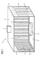
- FIG 1 schematically shows a perspective view of a microwave cavity 1.
- the cavity 1 comprises a bottom wall 2, a top wall 3 and three side walls 4, in more detail a left side wall, a right side wall and back side wall.
- a microwave source 5 which may be a microwave feeder having means for coupling microwaves generated by a magnetron into the cavity 1, is arranged at the top wall 3 and attached thereto in order to properly couple microwaves into the cavity 1. Approximately in the center of the bottom wall 2 a load 6 to be heated with microwaves emitted by the microwave source 5 is placed.
- each side wall 4 comprises one Fresnel reflective element 7 and each Fresnel reflective element 7 in turn comprises several facets 8.
- the facets 8 are linear, strip-shaped microwave reflective elements running along the side walls from the bottom wall to the top wall.
- the facets 8, in more detail reflective faces of the facets 8, are oriented in a special way as is described further below.
- FIG 2 and 3 show a cross-sectional and perspective view of a Fresnel reflective element 7.
- the facets 8 are oriented such that the Fresnel reflective element 7 has an ellipsoidal shaped aperture, which is indicated by the ellipse shown in FIG 2 .
- Such an aperture is advantageous for rectangular shaped active zones within the microwave cavity 1.
- Other active zones may require other apertures in order to obtain even and homogeneous heating.
- circular apertures are adequate for square active zones.
- microwaves emitted at a focal point can be parallelized and parallel microwaves impinging on the Fresnel reflective element 4 can be focused.
- FIG 4 shows a top view of a Fresnel reflective element 7 together with the microwave source 5.
- the microwave source 5 is positioned in or near the focal point of the Fresnel reflective element 7, or in other words, the facets are designed and oriented such that the microwave source 5 lies approximately in or near the focal point.
- Microwaves emitted by the microwave source 5 and impinging on the Fresnel reflective element 7 are parallelized, which is visualized in FIG 4 by central beams impinging on the facets 8 as well as shaded parallel strips.
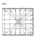
- FIG 5 shows a top view of the microwave cavity 1 having three Fresnel reflective elements 7.
- the Fresnel reflective elements 7, in particular facets 8 thereof, are arranged and adapted such that their focal points coincide with the position of the microwave source 5.
- the microwave source 5 may be a microwave feeder for coupling microwaves into the microwave cavity 1.
- Microwaves coupled into the microwave cavity 1 which impinge on the Fresnel reflective elements 7 prior to being absorbed by the load 6 are parallelized, i. e. reflected in parallel volume strips as defined by the orientation of the facets 8.
- reflection of microwaves emitted by the microwave source 5 is visualized by respective central beams.
- microwaves that are first reflected at a side wall 4 before being absorbed by the load 6 are distributed evenly over the volume of the microwave cavity 1, which is visualized my means of shaded strips and arrows in FIG 6 .
- This.favourable microwave distribution obtained in connection with the Fresnel reflective elements 7 leads to uniform heating patterns while preventing hot and cold spots.
- FIG 7 visualizes in a cross-sectional view microwave reflection within the microwave cavity 1.
- microwaves emitted by the microwave source 5 and having a component of propagation in a downward direction are reflected to the area in which the load 5 is located.
- Microwaves that are not absorbed by the load 5 and which are reflected at an inner wall once again will be focused to the active area of the microwave cavity 1 in which the load 6 is located.
- the Fresnel reflective elements 7 provided with inner walls 4 lead to a more uniform and even distribution of microwave radiation within the microwave cavity 1. Further, due to the fact that microwaves are also focussed towards the active area of the microwave cavity 1 excellent heating efficiency can be obtained.
- FIG 8 shows geometric relationships of a facet 8 of the Fresnel reflective element 7, which relationships are especially advantageous for obtaining uniform and effective heating.
- the relationships in principle apply to any facet 8 of the Fresnel reflective elements 7.
- a central beam as already shown in FIG 4 and FIG 5 is representative of microwave radiation impinging on the Fresnel reflective element 7.
- the angle ⁇ is the angle of inclination of the facet 8, i. e. the inclination of the facet 8 relative to the lateral extension of a respective side wall 4.
- the angle ⁇ is the microwave feeding angle, which is the angle between the central beam emanating from the microwave source 5 and a plane parallel to the respective side wall 4.
- the angle ⁇ is a mirror angle related to the surface normal of the respective Fresnel reflective element, or in more detail, the angle between the surface normal and the central beam, which can be designated as angle of incidence. Note that the values of angles ⁇ , ⁇ , and ⁇ have specific values for each facet.
- ⁇ rad 2 ⁇ arcsin ⁇
- these parameters may be adapted accordingly, wherein as a general rule, the width w f shall be greater than half the corresponding center wavelength of the microwave source, and the depth d f shall be smaller than a quarter of the center wavelength.
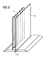
- FIG 9 shows a section of a Fresnel reflective element 7 that is shielded by a cover plate 9.
- the cover plate 9 is made from a microwave transparent material such as plastic, glass, pottery and the like.
- the cover plate 9 shields the inner wall 4 of the microwave cavity 1 carrying the Fresnel reflective element 7 from dust and soil and also protects the Fresnel reflective element 7 against damage.
- Such a cover plate 9 greatly simplifies cleaning of the inner walls, due to the fact that implementation of Fresnel reflective elements 7, in particular facets 8, leads to corrugated surface structures which, as a general rule, are more difficult to clean that smooth surfaces of cover plates 9.
- the cover plate 9 is retained in a groove 10 provided in the bottom 2 and/or top wall 3 of the microwave cavity 1.
- a groove 10 may simplify removal, insertion or replacement of respective cover plates 9 while providing a firm hold. If the groove 10 is adapted accordingly, the cover plate 9 may be removed and inserted in a sliding motion, in which the upper and lower edges of the cover plate 9 are guided in the grooves 10.
- other ways of attachment of the cover plate 9 are conceivable.
- the Fresnel reflective elements 7 are effective in providing a more even distribution of microwaves, leading to uniform heating patterns and excellent heating efficiency.
Landscapes
- Physics & Mathematics (AREA)
- Electromagnetism (AREA)
- Engineering & Computer Science (AREA)
- Power Engineering (AREA)
- Electric Ovens (AREA)
- Constitution Of High-Frequency Heating (AREA)
Abstract
Description
- The present application is directed to a microwave oven cavity and a microwave oven comprising such a cavity.
- Microwave oven cavities usually are adapted to heat specific loads in a microwave electric field generated by coupling electromagnetic waves, i. e. microwaves, into the microwave cavity.
- Standing electromagnetic waves establishing within the cavity make it difficult to generate or keep a constant and uniform electric field. This in turn results in a peak-to-peak variation in the intensity of electric field lines in the cavity, in particular preventing uniform heating of the targeted load.
- The value of the microwave power absorbed in the unit volume of the load to be heated is a function of several parameters as well as the generator's frequency, electric permittivity, the dielectric loss of the complex impedance loads or strength of the electric field inside the load. The last one is most significant and responsible for variations of temperature within the load.
- Generally, to ensure uniform heating or to prevent overheated areas, known microwave applicators are providing at least one of the following methods:
- a stirrer at a microwave feeding input which will change the incident angles of the electromagnetic field, thereby changing the positions of the standing microwaves; or
- moving the load position on heating area by using a rotating plate or a linear conveyor;
- The methods mentioned so far are comparatively elaborate and/or costly. Hence, there is still need to improve uniform heating and heating efficiency.
- It is therefore an object of the invention to overcome the known disadvantages. In particular, there shall be provided a microwave oven cavity with improved uniform heating and excellent heating efficiency. Further, a microwave oven shall be provided.
- This object is achieved by the independent claims. Embodiments thereof result from the dependent claims.
- According to claim 1, a microwave oven cavity is provided, in which at least one inner wall comprises at least one Fresnel reflective element. Such a Fresnel reflective element is adapted to reflect microwaves coupled from a microwave source into the cavity in a predetermined manner. The Fresnel reflective element may comprise several Fresnel zones, comparable to a Fresnel lens in optics. Reflection of the microwaves within the cavity is modified by the at least one Fresnel reflective element such that hot and/or cold spots in a load, which may be a food item for example, can be prevented. Hence, uniform heating and excellent heating efficiency can be obtained.
- The invention is in particular based on the finding, that one relevant factor for obtaining uniform heating is to ensure a correct path of microwaves within the microwave cavity. A correct or adequate path of microwaves inter alia depends on the inner geometry of the cavity, the wavelength or range of wavelengths of the microwave source and propagation modes of the electromagnetic field within the cavity.
- Further, the position of the microwave source, which may be a microwave feeder, i. e. the location where microwaves are coupled into the cavity plays a major role with respect to heating uniformity and heating efficiency.
- Therefore, in order to increase the heating uniformity and to reduce standing wave effects, the present invention proposes to use Fresnel reflective elements provided with the inner walls of the microwave oven cavity.
- Inner walls of a microwave oven cavity comprising one or several Fresnel reflective elements, in particular inner walls nearly completely covered or provided with Fresnel reflective elements, can be designated as Fresnel reflective walls. The Fresnel reflective elements can be considered to represent inverse Fresnel lenses, which are well known in optics.
- A Fresnel reflective element can comprise at least one facet, preferably of linear type. The term linear type shall mean that the facet runs in parallel and along a lateral or longitudinal direction of an inner wall, preferably a side wall of the cavity. Such a linear type facet can be thought to implement a reflective parallel strip having a certain geometry and reflectivity. Facets may be provided with an inner wall in a transversal or longitudinal direction thereof. The term of linear type shall in particular point out, that the facet is linear in at least one of its dimensions. If a Fresnel reflective element comprises several facets that are arranged side by side, and the geometry of the facets is adapted accordingly, a linear Fresnel reflector is obtained. Such a linear Fresnel reflector may reflect microwaves into parallel columnar volume elements of the cavity, but also may focus microwaves impinging on the Fresnel reflector to a given area within the cavity, preferably an area in which a load is placed or located.
- The use of Fresnel reflective elements or Fresnel reflective walls will lead to enhanced uniform heating and excellent heating efficiency. For example, three vertical walls of a conventional microwave cavity of a microwave oven can be Fresnel reflective walls.
- In providing such Fresnel reflective elements it is in particular possible to solve electromagnetic density issues of reflected waves, in particular in cases where a comparatively large amount of the microwave power is absorbed by the load.
- Each Fresnel reflective wall may have a different target area within the cavity, and may cover the active area within the microwave oven cavity not only with respect to the surface, but also with respect to the volume of a load.
- An aperture of the at least one Fresnel reflective element may be at least partially of circular, ellipsoidal, hyperbolic or parabolic shape. The shape of the aperture of Fresnel reflective elements making up a Fresnel reflector, inter alia may be selected according to shape and dimension of the microwave cavity and other relevant parameters. For example, a circular shape may be used with a square active area of the microwave cavity, and an elliptic shape may be used with a rectangular active area.
- In preferred embodiments, at least one side wall, preferably three side walls of the cavity, comprises at least one Fresnel reflective element having facets of linear type. It is preferred that the facets of such a linear Fresnel reflector run in a direction from a bottom to a top wall of the cavity. However, it shall be mentioned, that the position and orientation of the facets may depend on the position of the microwave source, or the microwave feeder, relative to the cavity, Facets running from bottom to top, or vice versa, can in particular be used for microwave sources or feeders arranged in or at the top or upper wall of the cavity.
- The Fresnel reflective elements running between opposite walls of the cavity, such as between the bottom and top wall or between opposite side walls, may extend over nearly the whole distance between respective walls, such as their lateral or longitudinal dimensions. In this case, excellent heating characteristics can be obtained. However, it is also possible that at least one Fresnel reflective element or facet thereof extends only over a section of respective wall dimensions. In the case that the Fresnel reflective elements extend between the bottom and top wall of the cavity, the longitudinal dimension of respective Fresnel reflective elements of facets preferably is equal to about the distance between the bottom and top wall. Here, a maximum of microwave energy can be applied to the load.
- In an embodiment, the at least one Fresnel reflective element is adapted to reflect at least microwaves of a given range of wavelengths, and wherein a width of the at least one Fresnel reflective element, preferably of each facet, at right angle to its longitudinal direction is greater than half of the center wavelength of the range of wavelengths. The term "range of wavelengths" shall in particular account for the fact that even "monochromatic" microwave sources generally emit a spectrum of microwave wavelengths. If a microwave source is used that in principle generates only one single wavelength, this single wavelength will correspond to the center wavelength. This situation applies to most microwave ovens which use magnetrons of given frequencies, such as 2.45 GHz and others.
- In the case that a microwave source of 2.45 GHz is used, the width is preferably in the range from 65 mm to 85 mm.
- In a further preferred embodiment, the depth of a Fresnel reflective element, preferably of each facet, at right angle both to the longitudinal direction thereof and to the inner wall is one quarter of the center wavelength of the range of wavelengths at the most. In the case, the microwave source is of 2.45 GHz type, the depth preferably is in the range from 5 mm to 30 mm.
- In a particular embodiment, at least one microwave source and at least one Fresnel reflective element are positioned and aligned such that


wherein - α is an angle of inclination of a Fresnel reflective element, in particular a facet, relative to a lateral dimension of a respective inner wall,
- β a microwave feeding angle, and
- γ is a mirror angle related to the surface normal of the respective Fresnel reflective element or facet.
- Depending on the angle of propagation of microwaves, the given arrangement causes microwaves impinging on a Fresnel reflective element either to be reflected in areas of parallel columnar volumes or to be focussed into a given active area.
- In particular with microwave sources of 2.45 GHz, it is of advantage if the angle of inclination α lies in the range from 3 degrees to 30 degrees, the microwave feeding angle P lies in the range from 30 degrees to 84 degrees and the mirror angle γ lies in the range from 6 degrees to 60 degrees.
- In a further preferred embodiment, the at least one Fresnel reflective element is shielded against dirt by a microwave transparent cover. The cover in particular can be made from at least one of glass, pottery and plastics. The Fresnel reflective element may be attached to the cover which means that the cover which functions as a substrate or carrier for the cover, or the cover may be positioned in front of a respective wall of the cavity, i. e. in front of the Fresnel reflective element.
- In order to obtain a maximal uniformity and effectiveness of heating it is of particular advantage if at least three side walls of the cavity are provided with Fresnel reflective elements.
- In an embodiment, the at least one Fresnel reflective element is arranged and designed such that microwaves emitted by the microwave source and impinging on the Fresnel reflective element are reflected into a respective parallel strip or columnar volume, and that microwaves impinging basically at right angle to the inner wall or inner walls are focused to a given area or volume, in particular an active zone, of the cavity. Here, in particular effective and uniform heating can be obtained.
- According to independent claim 15 there is provided a microwave oven comprising a microwave oven cavity of any embodiment as described beforehand. As to advantages and advantageous effects of the microwave oven, reference is made to the description above.
- Embodiments of the invention will now be described in connection with the annexed figures, in which
- Fig. 1
- schematically shows a perspective view of a microwave cavity;
- FIG 2
- shows a cross sectional view of a Fresnel reflective element;
- FIG 3
- shows a perspective view of the Fresnel reflective element;
- FIG 4
- shows a top view of a Fresnel reflective element together with a microwave source;
- FIG 5
- shows a top view of a the microwave cavity;
- FIG 6
- shows in a top view a microwave distribution in the microwave cavity;
- FIG 7
- visualizes in a cross-sectional view microwave reflection within the microwave cavity;
- FIG 8
- shows geometric relationships of facets of the Fresnel reflective elements;
- FIG 9
- shows a section of a Fresnel reflective element together with a cover plate.
- The following description of embodiments shall not be construed as limiting the scope of the invention. In particular, features jointly shown in any of the figures can be implemented alone or in any other combination as discussed further above.
- If not otherwise stated like elements are denoted by like reference signs throughout the figures. The figures may not be true to scale, and scales of different figures may be different.
-
FIG 1 schematically shows a perspective view of a microwave cavity 1. The cavity 1 comprises abottom wall 2, atop wall 3 and threeside walls 4, in more detail a left side wall, a right side wall and back side wall. - A
microwave source 5, which may be a microwave feeder having means for coupling microwaves generated by a magnetron into the cavity 1, is arranged at thetop wall 3 and attached thereto in order to properly couple microwaves into the cavity 1. Approximately in the center of the bottom wall 2 aload 6 to be heated with microwaves emitted by themicrowave source 5 is placed. - In order to ensure efficient and uniform heating, the three
side walls 4, comprise Fresnelreflective elements 7. In the present case, eachside wall 4 comprises one Fresnelreflective element 7 and each Fresnelreflective element 7 in turn comprisesseveral facets 8. Thefacets 8 are linear, strip-shaped microwave reflective elements running along the side walls from the bottom wall to the top wall. - In order to obtain uniform heating, the
facets 8, in more detail reflective faces of thefacets 8, are oriented in a special way as is described further below. -
FIG 2 and 3 show a cross-sectional and perspective view of a Fresnelreflective element 7. As can be seen, thefacets 8 are oriented such that the Fresnelreflective element 7 has an ellipsoidal shaped aperture, which is indicated by the ellipse shown inFIG 2 . Such an aperture is advantageous for rectangular shaped active zones within the microwave cavity 1. Other active zones may require other apertures in order to obtain even and homogeneous heating. For example, circular apertures are adequate for square active zones. - As can be seen from
FIG 2 , microwaves emitted at a focal point can be parallelized and parallel microwaves impinging on the Fresnelreflective element 4 can be focused. -
FIG 4 shows a top view of a Fresnelreflective element 7 together with themicrowave source 5. Themicrowave source 5 is positioned in or near the focal point of the Fresnelreflective element 7, or in other words, the facets are designed and oriented such that themicrowave source 5 lies approximately in or near the focal point. - Microwaves emitted by the
microwave source 5 and impinging on the Fresnelreflective element 7 are parallelized, which is visualized inFIG 4 by central beams impinging on thefacets 8 as well as shaded parallel strips. -
FIG 5 shows a top view of the microwave cavity 1 having three Fresnelreflective elements 7. The Fresnelreflective elements 7, inparticular facets 8 thereof, are arranged and adapted such that their focal points coincide with the position of themicrowave source 5. As already mentioned, themicrowave source 5 may be a microwave feeder for coupling microwaves into the microwave cavity 1. - Microwaves coupled into the microwave cavity 1 which impinge on the Fresnel
reflective elements 7 prior to being absorbed by theload 6 are parallelized, i. e. reflected in parallel volume strips as defined by the orientation of thefacets 8. InFIG 5 reflection of microwaves emitted by themicrowave source 5 is visualized by respective central beams. - As becomes clear from
FIG 4 and5 , microwaves that are first reflected at aside wall 4 before being absorbed by theload 6 are distributed evenly over the volume of the microwave cavity 1, which is visualized my means of shaded strips and arrows inFIG 6 . This.favourable microwave distribution obtained in connection with the Fresnelreflective elements 7 leads to uniform heating patterns while preventing hot and cold spots. -
FIG 7 visualizes in a cross-sectional view microwave reflection within the microwave cavity 1. As can be seen, microwaves emitted by themicrowave source 5 and having a component of propagation in a downward direction are reflected to the area in which theload 5 is located. - Microwaves that are not absorbed by the
load 5 and which are reflected at an inner wall once again will be focused to the active area of the microwave cavity 1 in which theload 6 is located. - In all, it can be seen, that the Fresnel
reflective elements 7 provided withinner walls 4 lead to a more uniform and even distribution of microwave radiation within the microwave cavity 1. Further, due to the fact that microwaves are also focussed towards the active area of the microwave cavity 1 excellent heating efficiency can be obtained. -
FIG 8 shows geometric relationships of afacet 8 of the Fresnelreflective element 7, which relationships are especially advantageous for obtaining uniform and effective heating. The relationships in principle apply to anyfacet 8 of the Fresnelreflective elements 7. A central beam as already shown inFIG 4 andFIG 5 is representative of microwave radiation impinging on the Fresnelreflective element 7. - In
FIG 8 , the angle α is the angle of inclination of thefacet 8, i. e. the inclination of thefacet 8 relative to the lateral extension of arespective side wall 4. The angle β is the microwave feeding angle, which is the angle between the central beam emanating from themicrowave source 5 and a plane parallel to therespective side wall 4. The angle γ is a mirror angle related to the surface normal of the respective Fresnel reflective element, or in more detail, the angle between the surface normal and the central beam, which can be designated as angle of incidence. Note that the values of angles α, β, and γ have specific values for each facet. - According to
FIG8 the following relationships between the angles α, β, and γ apply:
wherein - df is the depth of the
facet 8 under corresponding angle α, and - wf is he width of the
respective facet 8 at right angle to its longitudinal direction. - Using angular calculation methods the following equations apply:

- The above relationships more or less define the mutual arrangement of at least the
facets 8 of the Fresnel reflective elements and themicrowave source 5. As has been shown further above, using such an arrangement leads to more uniform heating patterns and excellent heating efficiency. - In a microwave oven having a
microwave source 5 operating at 2.45 GHz preferred values of the above parameters are as follows: - α : in the range from 3° to 30°
- β : in the range from 30° to 84°
- γ : in the range from 6° to 60°
- wf : in the range from 65 mm to 85 mm
- df : in the range from 5 mm to 30mm
- For other operating frequencies, these parameters may be adapted accordingly, wherein as a general rule, the width wf shall be greater than half the corresponding center wavelength of the microwave source, and the depth df shall be smaller than a quarter of the center wavelength.
-
FIG 9 shows a section of a Fresnelreflective element 7 that is shielded by acover plate 9. Thecover plate 9 is made from a microwave transparent material such as plastic, glass, pottery and the like. - The
cover plate 9 shields theinner wall 4 of the microwave cavity 1 carrying the Fresnelreflective element 7 from dust and soil and also protects the Fresnelreflective element 7 against damage. Such acover plate 9 greatly simplifies cleaning of the inner walls, due to the fact that implementation of Fresnelreflective elements 7, inparticular facets 8, leads to corrugated surface structures which, as a general rule, are more difficult to clean that smooth surfaces ofcover plates 9. - In the embodiment shown in
FIG 9 , thecover plate 9 is retained in agroove 10 provided in thebottom 2 and/ortop wall 3 of the microwave cavity 1. Such agroove 10 may simplify removal, insertion or replacement ofrespective cover plates 9 while providing a firm hold. If thegroove 10 is adapted accordingly, thecover plate 9 may be removed and inserted in a sliding motion, in which the upper and lower edges of thecover plate 9 are guided in thegrooves 10. However, also other ways of attachment of thecover plate 9 are conceivable. - In all, it can be seen, that the Fresnel
reflective elements 7 are effective in providing a more even distribution of microwaves, leading to uniform heating patterns and excellent heating efficiency. -
- 1
- microwave cavity
- 2
- bottom wall,
- 3
- top wall
- 4
- side wall
- 5
- microwave source
- 6
- load
- 7
- Fresnel reflective element
- 8
- facet
- 9
- cover plate
- 10
- groove
Claims (15)
- Microwave oven cavity (1) in which at least one inner wall (4) comprises at least one Fresnel reflective element (7) adapted to reflect microwaves coupled into the cavity (1) from a microwave source (5).
- Microwave oven cavity (1) according to claim 1,
wherein each Fresnel reflective element (7) comprises at least one facet (8), preferably of linear type, preferably running along a lateral or longitudinal direction of a side wall (4) of the cavity (1). - Microwave oven cavity (1) according to claim 1 or 2,
wherein an aperture of the at least one Fresnel reflective element (7) is of circular, ellipsoidal, hyperbolic or parabolic shape. - Microwave oven cavity (1) according to at least one of claims 1 to 3, wherein at least one side-wall (4) comprises at least one Fresnel reflective element (7) having facets (8) of linear type extending in a direction from a bottom (2) to a top wall (2) of the cavity (1).
- Microwave oven cavity (1) according to at least one of claims 1 to 4, wherein a Fresnel reflective element (7) running between opposite walls of the cavity (1) extends over nearly the whole distance between respective walls (2, 3, 4).
- Microwave oven cavity (1) according to at least one of claims 1 to 5, wherein the at least one Fresnel reflective element (7) is adapted to reflect at least microwaves of a given range of wavelengths, and wherein a width (wf) of the at least one Fresnel reflective element (7), preferably of each facet (8), at right angle to its longitudinal direction is greater than half of the center wavelength of the range of wavelengths.
- Microwave oven cavity (1) according to claim 6,
wherein the width (wf) is in the range from 65 mm to 85 mm. - Microwave oven cavity (1) according to at least one of claims 1 to 7, wherein the at least one Fresnel reflective element (7) is adapted to reflect microwaves of a given range of wavelengths, and wherein a depth (df) of the at least one Fresnel reflective element (7) at right angle both to the longitudinal direction thereof and to the inner wall (4) is one quarter of a center wavelength of the range of wavelength at the most.
- Microwave oven cavity (1) according to claim 8,
wherein the depth (df) is between 5 mm and 30 mm. - Microwave oven cavity (1) according at least one of claims 1 to 9, further comprising at least one microwave source (5), wherein at least one of the at least one Fresnel reflective element (7) and at least one microwave source (5) is positioned and aligned such that (i) α = ½(90°-β), (ii) β = 90° - 2α and (iii) γ = 2α, wherein α is an angle of inclination of a Fresnel reflective element (7) relative to a lateral dimension of a respective inner wall (4), β is a microwave feeding angle, and γis a mirror angle related to the surface normal of the respective Fresnel reflective element (7).
- Microwave oven cavity (1) according to claim 10,
wherein the angle of inclination α lies in the range from 3 degrees to 30 degrees, the microwave feeding angle β lies in the range from 30 degrees to 84 degrees and the mirror angle γ lies in the range from 6 degrees to 60 degrees. - Microwave oven cavity (1) according to at least one of claims 1 to 11, wherein the at least one Fresnel reflective element (7) is shielded against dirt by a microwave transparent cover (9), in particular made from at least one of glass, pottery and plastics.
- Microwave oven cavity (1) according to at least one of claims 1 to 12, wherein at least three side walls (4) thereof are provided with Fresnel reflective elements (7).
- Microwave oven cavity (1) according to at least one of claims 1 to 13, wherein the Fresnel reflective element (7) is arranged and designed such that microwaves emitted by the microwave source (5) and impinging on the Fresnel reflective element (7) are reflected into a respective parallel strip or columnar volume, and that microwaves impinging basically at right angle to the inner wall (4) are focused to a given area or volume (6) within the cavity (1).
- Microwave oven comprising a microwave oven cavity (1) according to at least one of claims 1 to 14.
Priority Applications (6)
| Application Number | Priority Date | Filing Date | Title |
|---|---|---|---|
| EP20100013871 EP2445313B1 (en) | 2010-10-21 | 2010-10-21 | Microwave oven cavity and microwave oven |
| BR112013009527-0A BR112013009527B1 (en) | 2010-10-21 | 2011-09-23 | MICROWAVE OVEN CAVITY AND MICROWAVE OVEN |
| CN2011800403100A CN103098543A (en) | 2010-10-21 | 2011-09-23 | Microwave oven cavity and microwave oven |
| US13/825,184 US9693400B2 (en) | 2010-10-21 | 2011-09-23 | Microwave oven cavity and microwave oven |
| PCT/EP2011/066550 WO2012052248A1 (en) | 2010-10-21 | 2011-09-23 | Microwave oven cavity and microwave oven |
| AU2011317761A AU2011317761B2 (en) | 2010-10-21 | 2011-09-23 | Microwave oven cavity and microwave oven |
Applications Claiming Priority (1)
| Application Number | Priority Date | Filing Date | Title |
|---|---|---|---|
| EP20100013871 EP2445313B1 (en) | 2010-10-21 | 2010-10-21 | Microwave oven cavity and microwave oven |
Publications (2)
| Publication Number | Publication Date |
|---|---|
| EP2445313A1 true EP2445313A1 (en) | 2012-04-25 |
| EP2445313B1 EP2445313B1 (en) | 2015-05-13 |
Family
ID=43513980
Family Applications (1)
| Application Number | Title | Priority Date | Filing Date |
|---|---|---|---|
| EP20100013871 Not-in-force EP2445313B1 (en) | 2010-10-21 | 2010-10-21 | Microwave oven cavity and microwave oven |
Country Status (6)
| Country | Link |
|---|---|
| US (1) | US9693400B2 (en) |
| EP (1) | EP2445313B1 (en) |
| CN (1) | CN103098543A (en) |
| AU (1) | AU2011317761B2 (en) |
| BR (1) | BR112013009527B1 (en) |
| WO (1) | WO2012052248A1 (en) |
Cited By (1)
| Publication number | Priority date | Publication date | Assignee | Title |
|---|---|---|---|---|
| CN103512058A (en) * | 2012-06-29 | 2014-01-15 | 太仓南极风能源设备有限公司 | Microwave oven |
Families Citing this family (8)
| Publication number | Priority date | Publication date | Assignee | Title |
|---|---|---|---|---|
| EP3143666B1 (en) | 2014-05-13 | 2018-12-19 | Centre National de la Recherche Scientifique (CNRS) | A microwave oven |
| US9823019B2 (en) * | 2014-07-17 | 2017-11-21 | Mitsubishi Electric Corporation | Microwave irradiating and heating device |
| CN108605390B (en) * | 2016-02-17 | 2021-03-12 | 松下电器产业株式会社 | microwave heating device |
| US10986705B2 (en) * | 2016-03-01 | 2021-04-20 | Samsung Electronics Co., Ltd. | Microwave oven |
| KR20180040362A (en) * | 2016-10-12 | 2018-04-20 | 삼성전자주식회사 | Electric oven including thermal diffusion layer |
| CN110024843B (en) * | 2019-05-21 | 2025-01-03 | 中国海洋大学 | 433MHz heating chamber and solid source industrial thawing equipment |
| CN112714527A (en) * | 2021-02-27 | 2021-04-27 | 云南师范大学 | Rectangular microwave reaction cavity structure with controllable metamaterial cavity wall |
| CN114709586B (en) * | 2022-04-07 | 2023-04-25 | 湖南大学 | A method for realizing a microwave resonant cavity capable of continuously translating the electromagnetic field in the microwave cavity |
Citations (3)
| Publication number | Priority date | Publication date | Assignee | Title |
|---|---|---|---|---|
| US5919391A (en) * | 1998-04-20 | 1999-07-06 | Daewoo Electronics Co., Ltd. | Microwave oven having arcuate concave portions in a cavity for distributing microwaves |
| WO2002063926A1 (en) * | 2001-02-05 | 2002-08-15 | Young Hee Lee | Apparatus for uniformly dispersing microwave and heating system using the same |
| US20060032447A1 (en) * | 2004-08-11 | 2006-02-16 | Industrial Technology Research Institute | Processing chamber with wave reflector |
Family Cites Families (20)
| Publication number | Priority date | Publication date | Assignee | Title |
|---|---|---|---|---|
| US4319125A (en) * | 1979-07-20 | 1982-03-09 | Prince Fred J | Infra-red radiant heater system |
| US4800090A (en) * | 1987-03-11 | 1989-01-24 | Musser's Potato Chips, Inc. | Infrared and microwave energy treatment of food |
| GB9015159D0 (en) * | 1990-07-10 | 1990-08-29 | Mawzones Dev | A phase correcting reflection zone plate for focusing microwaves |
| US5353037A (en) * | 1992-02-03 | 1994-10-04 | Jones Thad M | System for deicing dish mounted antennae |
| GB2269055B (en) * | 1992-07-09 | 1996-06-05 | Flat Antenna Co Ltd | Phase correcting zone plate |
| US5290985A (en) * | 1993-03-01 | 1994-03-01 | Jancic Betsy L | Microwave oven insert |
| KR100396765B1 (en) * | 2000-08-23 | 2003-09-02 | 엘지전자 주식회사 | Structure for guiding microwave in microwave oven range |
| US6507441B1 (en) * | 2000-10-16 | 2003-01-14 | Optid, Optical Identification Technologies Ltd. | Directed reflectors and systems utilizing same |
| US6559460B1 (en) * | 2000-10-31 | 2003-05-06 | Nordson Corporation | Ultraviolet lamp system and methods |
| US20040240034A1 (en) * | 2001-11-30 | 2004-12-02 | Scharf Bruce R. | Diffraction compensation using a patterned reflector |
| WO2005010597A2 (en) * | 2003-07-16 | 2005-02-03 | Tidal Photonics, Inc. | Apparatus and methods relating to concentration and shaping of illumination |
| US7498549B2 (en) * | 2003-10-24 | 2009-03-03 | Raytheon Company | Selective layer millimeter-wave surface-heating system and method |
| KR20090105747A (en) * | 2008-04-03 | 2009-10-07 | 삼성전자주식회사 | Optical scanning device and image forming device using the same |
| BRPI0923834A2 (en) * | 2008-12-30 | 2015-07-21 | Basf Se | Method for the production of shaped foam bodies, device for pressing heat formed foam bodies, and microwave irradiating unit |
| AU2010279305A1 (en) * | 2009-08-07 | 2012-03-01 | Perry Felix | Method and apparatus for surface and subsurface sanitizing of food products in a cooking appliance using ultraviolet light |
| US8854734B2 (en) * | 2009-11-12 | 2014-10-07 | Vela Technologies, Inc. | Integrating optical system and methods |
| US8496358B2 (en) * | 2010-03-06 | 2013-07-30 | John McEntee | Fresnel reflection device for concentration or collimation |
| CN101841946A (en) * | 2010-05-05 | 2010-09-22 | 许龙 | Application of tungsten in microwave heating and device using tungsten as microwave heating part |
| US9090114B1 (en) * | 2010-09-08 | 2015-07-28 | Brian A Stumm | Machine including LED-based UV radiation sources to process coatings |
| US9086483B2 (en) * | 2011-03-28 | 2015-07-21 | Northrop Grumman Guidance And Electronics Company, Inc. | Systems and methods for detecting and/or identifying materials |
-
2010
- 2010-10-21 EP EP20100013871 patent/EP2445313B1/en not_active Not-in-force
-
2011
- 2011-09-23 WO PCT/EP2011/066550 patent/WO2012052248A1/en not_active Ceased
- 2011-09-23 CN CN2011800403100A patent/CN103098543A/en active Pending
- 2011-09-23 US US13/825,184 patent/US9693400B2/en active Active
- 2011-09-23 BR BR112013009527-0A patent/BR112013009527B1/en not_active IP Right Cessation
- 2011-09-23 AU AU2011317761A patent/AU2011317761B2/en not_active Ceased
Patent Citations (3)
| Publication number | Priority date | Publication date | Assignee | Title |
|---|---|---|---|---|
| US5919391A (en) * | 1998-04-20 | 1999-07-06 | Daewoo Electronics Co., Ltd. | Microwave oven having arcuate concave portions in a cavity for distributing microwaves |
| WO2002063926A1 (en) * | 2001-02-05 | 2002-08-15 | Young Hee Lee | Apparatus for uniformly dispersing microwave and heating system using the same |
| US20060032447A1 (en) * | 2004-08-11 | 2006-02-16 | Industrial Technology Research Institute | Processing chamber with wave reflector |
Cited By (1)
| Publication number | Priority date | Publication date | Assignee | Title |
|---|---|---|---|---|
| CN103512058A (en) * | 2012-06-29 | 2014-01-15 | 太仓南极风能源设备有限公司 | Microwave oven |
Also Published As
| Publication number | Publication date |
|---|---|
| WO2012052248A1 (en) | 2012-04-26 |
| AU2011317761B2 (en) | 2014-08-14 |
| BR112013009527B1 (en) | 2020-10-06 |
| AU2011317761A1 (en) | 2013-03-28 |
| BR112013009527A2 (en) | 2016-07-12 |
| US20130213956A1 (en) | 2013-08-22 |
| EP2445313B1 (en) | 2015-05-13 |
| CN103098543A (en) | 2013-05-08 |
| US9693400B2 (en) | 2017-06-27 |
Similar Documents
| Publication | Publication Date | Title |
|---|---|---|
| EP2445313B1 (en) | Microwave oven cavity and microwave oven | |
| US4354083A (en) | Microwave oven with novel energy distribution arrangement | |
| US10506672B2 (en) | Microwave oven with a waveguide including a reflector element | |
| EP2852251A1 (en) | Microwave heating device | |
| JP6874756B2 (en) | Microwave heating device | |
| AU6338499A (en) | Microwave oven with browning device | |
| KR100458670B1 (en) | Electric cooking oven | |
| WO2016006249A1 (en) | Microwave heating device | |
| EP0274164B1 (en) | A microwave oven | |
| TWI713411B (en) | Microwave heating device | |
| TWI686104B (en) | Microwave heating device | |
| TWI686103B (en) | Microwave heating device | |
| JP6671005B2 (en) | Microwave heating equipment | |
| JP7378019B2 (en) | Microwave processing equipment | |
| TWI711343B (en) | Microwave heating device | |
| RU2265927C1 (en) | Waveguide microwave power radiator | |
| US20090166354A1 (en) | Microwave Heating Applicator | |
| TWI700465B (en) | Microwave heating device | |
| JPH08321379A (en) | Cooking device | |
| JPWO2019087418A1 (en) | Cooker | |
| JP2000068044A (en) | Microwave oven | |
| JP2005019195A (en) | High frequency heating device | |
| JP2005183065A (en) | High frequency heating device | |
| JPH0142584B2 (en) |
Legal Events
| Date | Code | Title | Description |
|---|---|---|---|
| 17P | Request for examination filed |
Effective date: 20110303 |
|
| AK | Designated contracting states |
Kind code of ref document: A1 Designated state(s): AL AT BE BG CH CY CZ DE DK EE ES FI FR GB GR HR HU IE IS IT LI LT LU LV MC MK MT NL NO PL PT RO RS SE SI SK SM TR |
|
| AX | Request for extension of the european patent |
Extension state: BA ME |
|
| PUAI | Public reference made under article 153(3) epc to a published international application that has entered the european phase |
Free format text: ORIGINAL CODE: 0009012 |
|
| GRAP | Despatch of communication of intention to grant a patent |
Free format text: ORIGINAL CODE: EPIDOSNIGR1 |
|
| INTG | Intention to grant announced |
Effective date: 20150123 |
|
| GRAS | Grant fee paid |
Free format text: ORIGINAL CODE: EPIDOSNIGR3 |
|
| GRAA | (expected) grant |
Free format text: ORIGINAL CODE: 0009210 |
|
| AK | Designated contracting states |
Kind code of ref document: B1 Designated state(s): AL AT BE BG CH CY CZ DE DK EE ES FI FR GB GR HR HU IE IS IT LI LT LU LV MC MK MT NL NO PL PT RO RS SE SI SK SM TR |
|
| REG | Reference to a national code |
Ref country code: GB Ref legal event code: FG4D |
|
| REG | Reference to a national code |
Ref country code: CH Ref legal event code: EP |
|
| REG | Reference to a national code |
Ref country code: IE Ref legal event code: FG4D |
|
| REG | Reference to a national code |
Ref country code: AT Ref legal event code: REF Ref document number: 727210 Country of ref document: AT Kind code of ref document: T Effective date: 20150615 |
|
| REG | Reference to a national code |
Ref country code: DE Ref legal event code: R096 Ref document number: 602010024602 Country of ref document: DE Effective date: 20150625 |
|
| RIN2 | Information on inventor provided after grant (corrected) |
Inventor name: TCACIUC, SORIN |
|
| REG | Reference to a national code |
Ref country code: AT Ref legal event code: MK05 Ref document number: 727210 Country of ref document: AT Kind code of ref document: T Effective date: 20150513 |
|
| REG | Reference to a national code |
Ref country code: NL Ref legal event code: MP Effective date: 20150513 |
|
| REG | Reference to a national code |
Ref country code: LT Ref legal event code: MG4D |
|
| PG25 | Lapsed in a contracting state [announced via postgrant information from national office to epo] |
Ref country code: NO Free format text: LAPSE BECAUSE OF FAILURE TO SUBMIT A TRANSLATION OF THE DESCRIPTION OR TO PAY THE FEE WITHIN THE PRESCRIBED TIME-LIMIT Effective date: 20150813 Ref country code: LT Free format text: LAPSE BECAUSE OF FAILURE TO SUBMIT A TRANSLATION OF THE DESCRIPTION OR TO PAY THE FEE WITHIN THE PRESCRIBED TIME-LIMIT Effective date: 20150513 Ref country code: FI Free format text: LAPSE BECAUSE OF FAILURE TO SUBMIT A TRANSLATION OF THE DESCRIPTION OR TO PAY THE FEE WITHIN THE PRESCRIBED TIME-LIMIT Effective date: 20150513 Ref country code: PT Free format text: LAPSE BECAUSE OF FAILURE TO SUBMIT A TRANSLATION OF THE DESCRIPTION OR TO PAY THE FEE WITHIN THE PRESCRIBED TIME-LIMIT Effective date: 20150914 Ref country code: ES Free format text: LAPSE BECAUSE OF FAILURE TO SUBMIT A TRANSLATION OF THE DESCRIPTION OR TO PAY THE FEE WITHIN THE PRESCRIBED TIME-LIMIT Effective date: 20150513 Ref country code: HR Free format text: LAPSE BECAUSE OF FAILURE TO SUBMIT A TRANSLATION OF THE DESCRIPTION OR TO PAY THE FEE WITHIN THE PRESCRIBED TIME-LIMIT Effective date: 20150513 |
|
| PG25 | Lapsed in a contracting state [announced via postgrant information from national office to epo] |
Ref country code: BG Free format text: LAPSE BECAUSE OF FAILURE TO SUBMIT A TRANSLATION OF THE DESCRIPTION OR TO PAY THE FEE WITHIN THE PRESCRIBED TIME-LIMIT Effective date: 20150813 Ref country code: IS Free format text: LAPSE BECAUSE OF FAILURE TO SUBMIT A TRANSLATION OF THE DESCRIPTION OR TO PAY THE FEE WITHIN THE PRESCRIBED TIME-LIMIT Effective date: 20150913 Ref country code: RS Free format text: LAPSE BECAUSE OF FAILURE TO SUBMIT A TRANSLATION OF THE DESCRIPTION OR TO PAY THE FEE WITHIN THE PRESCRIBED TIME-LIMIT Effective date: 20150513 Ref country code: AT Free format text: LAPSE BECAUSE OF FAILURE TO SUBMIT A TRANSLATION OF THE DESCRIPTION OR TO PAY THE FEE WITHIN THE PRESCRIBED TIME-LIMIT Effective date: 20150513 Ref country code: LV Free format text: LAPSE BECAUSE OF FAILURE TO SUBMIT A TRANSLATION OF THE DESCRIPTION OR TO PAY THE FEE WITHIN THE PRESCRIBED TIME-LIMIT Effective date: 20150513 Ref country code: GR Free format text: LAPSE BECAUSE OF FAILURE TO SUBMIT A TRANSLATION OF THE DESCRIPTION OR TO PAY THE FEE WITHIN THE PRESCRIBED TIME-LIMIT Effective date: 20150814 |
|
| PG25 | Lapsed in a contracting state [announced via postgrant information from national office to epo] |
Ref country code: EE Free format text: LAPSE BECAUSE OF FAILURE TO SUBMIT A TRANSLATION OF THE DESCRIPTION OR TO PAY THE FEE WITHIN THE PRESCRIBED TIME-LIMIT Effective date: 20150513 Ref country code: DK Free format text: LAPSE BECAUSE OF FAILURE TO SUBMIT A TRANSLATION OF THE DESCRIPTION OR TO PAY THE FEE WITHIN THE PRESCRIBED TIME-LIMIT Effective date: 20150513 |
|
| REG | Reference to a national code |
Ref country code: DE Ref legal event code: R097 Ref document number: 602010024602 Country of ref document: DE |
|
| PG25 | Lapsed in a contracting state [announced via postgrant information from national office to epo] |
Ref country code: CZ Free format text: LAPSE BECAUSE OF FAILURE TO SUBMIT A TRANSLATION OF THE DESCRIPTION OR TO PAY THE FEE WITHIN THE PRESCRIBED TIME-LIMIT Effective date: 20150513 Ref country code: PL Free format text: LAPSE BECAUSE OF FAILURE TO SUBMIT A TRANSLATION OF THE DESCRIPTION OR TO PAY THE FEE WITHIN THE PRESCRIBED TIME-LIMIT Effective date: 20150513 Ref country code: RO Free format text: LAPSE BECAUSE OF NON-PAYMENT OF DUE FEES Effective date: 20150513 Ref country code: SK Free format text: LAPSE BECAUSE OF FAILURE TO SUBMIT A TRANSLATION OF THE DESCRIPTION OR TO PAY THE FEE WITHIN THE PRESCRIBED TIME-LIMIT Effective date: 20150513 |
|
| PLBE | No opposition filed within time limit |
Free format text: ORIGINAL CODE: 0009261 |
|
| STAA | Information on the status of an ep patent application or granted ep patent |
Free format text: STATUS: NO OPPOSITION FILED WITHIN TIME LIMIT |
|
| 26N | No opposition filed |
Effective date: 20160216 |
|
| PG25 | Lapsed in a contracting state [announced via postgrant information from national office to epo] |
Ref country code: IT Free format text: LAPSE BECAUSE OF FAILURE TO SUBMIT A TRANSLATION OF THE DESCRIPTION OR TO PAY THE FEE WITHIN THE PRESCRIBED TIME-LIMIT Effective date: 20150513 |
|
| PG25 | Lapsed in a contracting state [announced via postgrant information from national office to epo] |
Ref country code: SI Free format text: LAPSE BECAUSE OF FAILURE TO SUBMIT A TRANSLATION OF THE DESCRIPTION OR TO PAY THE FEE WITHIN THE PRESCRIBED TIME-LIMIT Effective date: 20150513 Ref country code: LU Free format text: LAPSE BECAUSE OF FAILURE TO SUBMIT A TRANSLATION OF THE DESCRIPTION OR TO PAY THE FEE WITHIN THE PRESCRIBED TIME-LIMIT Effective date: 20151021 |
|
| REG | Reference to a national code |
Ref country code: CH Ref legal event code: PL |
|
| GBPC | Gb: european patent ceased through non-payment of renewal fee |
Effective date: 20151021 |
|
| PG25 | Lapsed in a contracting state [announced via postgrant information from national office to epo] |
Ref country code: MC Free format text: LAPSE BECAUSE OF FAILURE TO SUBMIT A TRANSLATION OF THE DESCRIPTION OR TO PAY THE FEE WITHIN THE PRESCRIBED TIME-LIMIT Effective date: 20150513 |
|
| REG | Reference to a national code |
Ref country code: IE Ref legal event code: MM4A |
|
| PG25 | Lapsed in a contracting state [announced via postgrant information from national office to epo] |
Ref country code: LI Free format text: LAPSE BECAUSE OF NON-PAYMENT OF DUE FEES Effective date: 20151031 Ref country code: GB Free format text: LAPSE BECAUSE OF NON-PAYMENT OF DUE FEES Effective date: 20151021 Ref country code: CH Free format text: LAPSE BECAUSE OF NON-PAYMENT OF DUE FEES Effective date: 20151031 |
|
| REG | Reference to a national code |
Ref country code: FR Ref legal event code: ST Effective date: 20160630 |
|
| PG25 | Lapsed in a contracting state [announced via postgrant information from national office to epo] |
Ref country code: FR Free format text: LAPSE BECAUSE OF NON-PAYMENT OF DUE FEES Effective date: 20151102 Ref country code: BE Free format text: LAPSE BECAUSE OF FAILURE TO SUBMIT A TRANSLATION OF THE DESCRIPTION OR TO PAY THE FEE WITHIN THE PRESCRIBED TIME-LIMIT Effective date: 20150513 |
|
| PG25 | Lapsed in a contracting state [announced via postgrant information from national office to epo] |
Ref country code: IE Free format text: LAPSE BECAUSE OF NON-PAYMENT OF DUE FEES Effective date: 20151021 |
|
| PG25 | Lapsed in a contracting state [announced via postgrant information from national office to epo] |
Ref country code: HU Free format text: LAPSE BECAUSE OF FAILURE TO SUBMIT A TRANSLATION OF THE DESCRIPTION OR TO PAY THE FEE WITHIN THE PRESCRIBED TIME-LIMIT; INVALID AB INITIO Effective date: 20101021 Ref country code: SM Free format text: LAPSE BECAUSE OF FAILURE TO SUBMIT A TRANSLATION OF THE DESCRIPTION OR TO PAY THE FEE WITHIN THE PRESCRIBED TIME-LIMIT Effective date: 20150513 |
|
| PG25 | Lapsed in a contracting state [announced via postgrant information from national office to epo] |
Ref country code: NL Free format text: LAPSE BECAUSE OF FAILURE TO SUBMIT A TRANSLATION OF THE DESCRIPTION OR TO PAY THE FEE WITHIN THE PRESCRIBED TIME-LIMIT Effective date: 20150513 Ref country code: CY Free format text: LAPSE BECAUSE OF FAILURE TO SUBMIT A TRANSLATION OF THE DESCRIPTION OR TO PAY THE FEE WITHIN THE PRESCRIBED TIME-LIMIT Effective date: 20150513 Ref country code: SE Free format text: LAPSE BECAUSE OF FAILURE TO SUBMIT A TRANSLATION OF THE DESCRIPTION OR TO PAY THE FEE WITHIN THE PRESCRIBED TIME-LIMIT Effective date: 20150513 |
|
| PG25 | Lapsed in a contracting state [announced via postgrant information from national office to epo] |
Ref country code: TR Free format text: LAPSE BECAUSE OF FAILURE TO SUBMIT A TRANSLATION OF THE DESCRIPTION OR TO PAY THE FEE WITHIN THE PRESCRIBED TIME-LIMIT Effective date: 20150513 Ref country code: MT Free format text: LAPSE BECAUSE OF FAILURE TO SUBMIT A TRANSLATION OF THE DESCRIPTION OR TO PAY THE FEE WITHIN THE PRESCRIBED TIME-LIMIT Effective date: 20150513 |
|
| PG25 | Lapsed in a contracting state [announced via postgrant information from national office to epo] |
Ref country code: MK Free format text: LAPSE BECAUSE OF FAILURE TO SUBMIT A TRANSLATION OF THE DESCRIPTION OR TO PAY THE FEE WITHIN THE PRESCRIBED TIME-LIMIT Effective date: 20150513 |
|
| PG25 | Lapsed in a contracting state [announced via postgrant information from national office to epo] |
Ref country code: AL Free format text: LAPSE BECAUSE OF FAILURE TO SUBMIT A TRANSLATION OF THE DESCRIPTION OR TO PAY THE FEE WITHIN THE PRESCRIBED TIME-LIMIT Effective date: 20150513 |
|
| PGFP | Annual fee paid to national office [announced via postgrant information from national office to epo] |
Ref country code: DE Payment date: 20221019 Year of fee payment: 13 |
|
| P01 | Opt-out of the competence of the unified patent court (upc) registered |
Effective date: 20230625 |
|
| REG | Reference to a national code |
Ref country code: DE Ref legal event code: R119 Ref document number: 602010024602 Country of ref document: DE |
|
| PG25 | Lapsed in a contracting state [announced via postgrant information from national office to epo] |
Ref country code: DE Free format text: LAPSE BECAUSE OF NON-PAYMENT OF DUE FEES Effective date: 20240501 |