EP2445055A1 - Agencement d'antenne - Google Patents
Agencement d'antenne Download PDFInfo
- Publication number
- EP2445055A1 EP2445055A1 EP10382279A EP10382279A EP2445055A1 EP 2445055 A1 EP2445055 A1 EP 2445055A1 EP 10382279 A EP10382279 A EP 10382279A EP 10382279 A EP10382279 A EP 10382279A EP 2445055 A1 EP2445055 A1 EP 2445055A1
- Authority
- EP
- European Patent Office
- Prior art keywords
- antenna
- director
- arrangement according
- working frequency
- director element
- Prior art date
- Legal status (The legal status is an assumption and is not a legal conclusion. Google has not performed a legal analysis and makes no representation as to the accuracy of the status listed.)
- Withdrawn
Links
- 230000005540 biological transmission Effects 0.000 claims abstract description 9
- 230000003044 adaptive effect Effects 0.000 description 5
- 238000005516 engineering process Methods 0.000 description 4
- 238000003491 array Methods 0.000 description 1
- 230000015556 catabolic process Effects 0.000 description 1
- 238000006731 degradation reaction Methods 0.000 description 1
- 230000001419 dependent effect Effects 0.000 description 1
- 230000007613 environmental effect Effects 0.000 description 1
- 230000003203 everyday effect Effects 0.000 description 1
- 230000003993 interaction Effects 0.000 description 1
- 230000003071 parasitic effect Effects 0.000 description 1
Images

Classifications
-
- H—ELECTRICITY
- H01—ELECTRIC ELEMENTS
- H01Q—ANTENNAS, i.e. RADIO AERIALS
- H01Q19/00—Combinations of primary active antenna elements and units with secondary devices, e.g. with quasi-optical devices, for giving the antenna a desired directional characteristic
- H01Q19/28—Combinations of primary active antenna elements and units with secondary devices, e.g. with quasi-optical devices, for giving the antenna a desired directional characteristic using a secondary device in the form of two or more substantially straight conductive elements
- H01Q19/30—Combinations of primary active antenna elements and units with secondary devices, e.g. with quasi-optical devices, for giving the antenna a desired directional characteristic using a secondary device in the form of two or more substantially straight conductive elements the primary active element being centre-fed and substantially straight, e.g. Yagi antenna
-
- H—ELECTRICITY
- H01—ELECTRIC ELEMENTS
- H01Q—ANTENNAS, i.e. RADIO AERIALS
- H01Q5/00—Arrangements for simultaneous operation of antennas on two or more different wavebands, e.g. dual-band or multi-band arrangements
- H01Q5/40—Imbricated or interleaved structures; Combined or electromagnetically coupled arrangements, e.g. comprising two or more non-connected fed radiating elements
- H01Q5/48—Combinations of two or more dipole type antennas
- H01Q5/49—Combinations of two or more dipole type antennas with parasitic elements used for purposes other than for dual-band or multi-band, e.g. imbricated Yagi antennas
Definitions
- the invention relates to an antenna arrangement for wireless communication networks.
- the invention relates to a multiband antenna arrangement.
- MNOs Mobile Telecommunications Network Operators
- the ideal solution would be a multi-band antenna with small size and good directivity.
- Yagi antenna is a directional antenna system, it has one dipole connected to the transmission line and a number of equally spaced unconnected dipoles mounted parallel to the first in the same horizontal plane to serve as directors and reflectors, it is a but it only works in one band.
- Each one of the antenna elements is fed with an Adaptive Antenna Systems (AAS) element, where the antenna element can be the deep antenna solution or the traditional antenna solutions; the main challenge for the current Wideband Single RAN (Radio Access Network) solutions is the duplexer, which allows a transmitter operating on one frequency and a receiver operating on a different frequency to share one common antenna with a minimum of interaction and degradation of the different RF signals.
- AAS Adaptive Antenna Systems
- Radio receivers can be damaged if high level RF signals, like those directly from a transmitter output, is applied to the receiver antenna. Additionally, receivers may become 'desensitized' (or 'de-sensed') and not receive weak signals when high noise levels or another signal near the receive frequency is present at the receivers antenna input.
- radio receivers and transmitters cannot be directly connected to the same antenna without some device being used to:
- AAS Single band Adaptive Antenna Systems
- an antenna arrangement comprising:
- This antenna arrangement ensures a good directivity working in different bands and avoiding the need for either bulky antennas, or antenna sites having several antennas since as it won't be necessary to place an antenna for each mobile frequency, band or technology.
- the antenna arrangement will thus avoid the implementation of large size antennas in the sites. The latter is also to the environmental impact of the antenna hereby described, since the multiband antenna object of the invention may substitute several antennas working in different bands in mobile frequencies.
- the multiband antenna object of the invention opposite to those disclosed in the previous art has more than one director elements; as the skilled in the art would appreciate having more directors means having more gain.
- the antenna elements are either passive or active and this feature is fixed and immutable.
- the director elements behave both as active and as passive elements depending on the working frequency (i.e. when working at 900MHz, the 900MHz dipole will behave as a director (active element) but when the working frequency is shifted to 1800MHz then the 900MHz dipole will behave as a passive element). Having passive elements improves the gain, whereas having active elements allows optimizing the gain for each band independently.
- the antenna arrangement hereby described has a configuration defined by one or more arrays, thus having more diversity in the RX;
- the multi-band antenna of the invention might have a 2D array configuration although a 3D array with orthogonal elements is preferred since it provides more diversity in the RX
- the spacing is chosen depending of which spacing frequency gives better gain.
- the antenna arrangement has a fixed value for the distance between each element; said distance is hereby presented as a function of the wavelength and the working frequency F:
- the driven which is arranged at a distance comprised between 37.5 F and 45 F metres from the reflector (being F is the working frequency of the antenna); following the driven we find the first director arranged at a distance set between 37.5 F and 45 F metres (being F is the working frequency of the antenna). Since the antenna may have more than one director we may find a second director arranged next to the first director (in the opposite direction to that of the reflector) at a distance set between 45 F and 75 F metres (being F is the working frequency).
- the multiband antenna may comprises as many directors as needed, successive directors should follow the rule described above, this means to apply a reduction factor set between 1.5 F and 10 F .
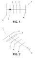
- figure 1 we can see the outline of the implementation of the antenna (1) arrangement object of the invention depicted in figure 1 .
- the antenna (1) arrangement has a reflector element (2) working in working frequency F set at 900 MHz, with the reflector element (2), a driven element (3) and several director elements (4,4',4",4"') being arranged in parallel and comprised in the same plane. As shown in figure 2 the reflector element (2) is separated from the driven element (3), the driven element (3) from the director elements (4,4',4",4"'), all of them are separated by a distance which is frequency F dependent, being F the working frequency.
- the antenna (1) arrangement detailed in this preferred embodiment works in different bands, namely: 900Mhz, 1800Mhz, 2100MHz and 2600MHz; in this preferred embodiment the reflector element (2) works in 900MHz, thus taking into account the relationship between working frequency F and length the sizes of the elements yield a relationship as follows:
- the above mentioned elements are arranged forming a flat multiband antenna (1) with all of the reflector element (2), the driven element (3) and the director elements (4,4',4",4"') are comprised in the same plane and prearranged as follows.
- the reflector element (2) is allocated at the very end of the multiband antenna (1) and is separated from the next element of the antenna (1), the driven element (3), by a distance comprised between 37.5 F and 45 F metres (being F is the working frequency of the antenna); following the driven element (3) we find the first director element (4) arranged at a distance set between 37.5 F and 45 F metres (being F is the working frequency of the antenna) from the driven (3). Since in this embodiment the multiband antenna (1) works in several frequencies, the antenna (1) has more than one director element (4,4',4",4"'); consequently the second director element (4') is arranged next to the first director element (4) (in the opposite direction to that of the driven element (3)) at a distance set between 45 F and 75 F metres (being F is the working frequency).
- the remaining working frequency is handled by the third director element (4") which is set at a distance set between 60 F and 75 F metres (being F is the working frequency) from the second director element (4"). If needed, any additional director element (4"') is mounted separated from the third director element (4") at a distance of at least 75 F metres.
- Another embodiment of the antenna (1) arrangement of the invention provides a solution for Adaptive Antenna Systems (AAS) using duplexers; wherein the transmission is done through a broadband dipole and the reception is splitted between different dipoles: each band through a different dipole.
- AAS Adaptive Antenna Systems
- AAS Wideband Adaptive Antenna Systems
- TX2 As a filter of RX2 has to reject the Tx signal from 2 TX (TX1 band and TX2 band), the difficulty is the double comparing to DUP of Single Band system. It is the same for TX1, a 1805 ⁇ 1880MHz filter.
- the RX2 band located in between the two TX bands is not received by dipol f1-f2 so duplexer is simplified as seen in figures 3 and 4 .
- AAS Adaptive Antenna Systems
Landscapes
- Physics & Mathematics (AREA)
- Electromagnetism (AREA)
- Aerials With Secondary Devices (AREA)
- Variable-Direction Aerials And Aerial Arrays (AREA)
Priority Applications (2)
| Application Number | Priority Date | Filing Date | Title |
|---|---|---|---|
| EP10382279A EP2445055A1 (fr) | 2010-10-25 | 2010-10-25 | Agencement d'antenne |
| US13/280,511 US8803753B2 (en) | 2010-10-25 | 2011-10-25 | Antenna arrangement |
Applications Claiming Priority (1)
| Application Number | Priority Date | Filing Date | Title |
|---|---|---|---|
| EP10382279A EP2445055A1 (fr) | 2010-10-25 | 2010-10-25 | Agencement d'antenne |
Publications (1)
| Publication Number | Publication Date |
|---|---|
| EP2445055A1 true EP2445055A1 (fr) | 2012-04-25 |
Family
ID=43431127
Family Applications (1)
| Application Number | Title | Priority Date | Filing Date |
|---|---|---|---|
| EP10382279A Withdrawn EP2445055A1 (fr) | 2010-10-25 | 2010-10-25 | Agencement d'antenne |
Country Status (2)
| Country | Link |
|---|---|
| US (1) | US8803753B2 (fr) |
| EP (1) | EP2445055A1 (fr) |
Cited By (1)
| Publication number | Priority date | Publication date | Assignee | Title |
|---|---|---|---|---|
| US11056788B2 (en) * | 2016-04-27 | 2021-07-06 | Cisco Technology, Inc. | Method of making a dual-band yagi-uda antenna array |
Citations (4)
| Publication number | Priority date | Publication date | Assignee | Title |
|---|---|---|---|---|
| JP2000278037A (ja) * | 1999-03-25 | 2000-10-06 | Tdk Corp | チップアンテナ |
| WO2005036694A2 (fr) * | 2003-10-02 | 2005-04-21 | Emag Technologies, Inc. | Systeme d'antenne integre dans une structure support pour la consultation d'un transpondeur de capteur de pneumatique |
| JP2006049945A (ja) * | 2004-07-30 | 2006-02-16 | Maspro Denkoh Corp | 八木・宇田式アンテナ装置 |
| KR200439899Y1 (ko) * | 2006-12-05 | 2008-05-13 | (주)에이스안테나 | 야기 안테나와 대수주기 안테나가 결합된 안테나 시스템 |
Family Cites Families (4)
| Publication number | Priority date | Publication date | Assignee | Title |
|---|---|---|---|---|
| US4028709A (en) * | 1975-09-10 | 1977-06-07 | The United States Of America As Represented By The Field Operations Bureau Of The Federal Communications Commission | Adjustable yagi antenna |
| US4218686A (en) * | 1978-02-23 | 1980-08-19 | Blonder-Tongue Laboratories, Inc. | Yagi-type antennas and method |
| US6307524B1 (en) * | 2000-01-18 | 2001-10-23 | Core Technology, Inc. | Yagi antenna having matching coaxial cable and driven element impedances |
| US7629938B1 (en) * | 2006-07-24 | 2009-12-08 | The United States Of America As Represented By The Secretary Of The Navy | Open Yaggi antenna array |
-
2010
- 2010-10-25 EP EP10382279A patent/EP2445055A1/fr not_active Withdrawn
-
2011
- 2011-10-25 US US13/280,511 patent/US8803753B2/en not_active Expired - Fee Related
Patent Citations (4)
| Publication number | Priority date | Publication date | Assignee | Title |
|---|---|---|---|---|
| JP2000278037A (ja) * | 1999-03-25 | 2000-10-06 | Tdk Corp | チップアンテナ |
| WO2005036694A2 (fr) * | 2003-10-02 | 2005-04-21 | Emag Technologies, Inc. | Systeme d'antenne integre dans une structure support pour la consultation d'un transpondeur de capteur de pneumatique |
| JP2006049945A (ja) * | 2004-07-30 | 2006-02-16 | Maspro Denkoh Corp | 八木・宇田式アンテナ装置 |
| KR200439899Y1 (ko) * | 2006-12-05 | 2008-05-13 | (주)에이스안테나 | 야기 안테나와 대수주기 안테나가 결합된 안테나 시스템 |
Non-Patent Citations (1)
| Title |
|---|
| KARL ROTHAMMEL: "Antennenbuch", 1 January 1984, TELEKOSMOS-VERLAG FRANCKH'SCHE VERLAGSHANDLUNG, Stuttgart, Germany, ISBN: 3-440-04791-1, XP002617550 * |
Cited By (1)
| Publication number | Priority date | Publication date | Assignee | Title |
|---|---|---|---|---|
| US11056788B2 (en) * | 2016-04-27 | 2021-07-06 | Cisco Technology, Inc. | Method of making a dual-band yagi-uda antenna array |
Also Published As
| Publication number | Publication date |
|---|---|
| US8803753B2 (en) | 2014-08-12 |
| US20120127052A1 (en) | 2012-05-24 |
Similar Documents
| Publication | Publication Date | Title |
|---|---|---|
| EP2041840B1 (fr) | Dispositif d'antenne multibande | |
| US6943746B2 (en) | Radio device and antenna structure | |
| US8922447B2 (en) | Smart antenna | |
| US20050179607A1 (en) | Method and apparatus for dynamically selecting the best antennas/mode ports for transmission and reception | |
| EP2038962B1 (fr) | Système d'antenne compacte, multibande et multimode | |
| CN104981939A (zh) | 一种天线装置以及基站 | |
| EP2617098B1 (fr) | Antenne capable d'une opération en diversitée | |
| EP1770874A1 (fr) | système d'antenne pour une station de radiocommunication, et station de radiocommunication comportant un tel système | |
| EP3574552B1 (fr) | Procédé et appareil pour système d'antenne mimo multibande à alimentation multiple | |
| CN105009361A (zh) | 一种天线装置以及基站 | |
| EP2999046A1 (fr) | Système à multiples antennes et terminal mobile | |
| US9225381B2 (en) | Tunable quality factor | |
| CN102576936A (zh) | 用于减少通信设备中的近场辐射和特殊吸收比率(sar)值的方法 | |
| EP3683890B1 (fr) | Dispositif électronique et structure d'antenne associée | |
| US9478860B2 (en) | Multiband antenna | |
| EP3622581B1 (fr) | Antenne à large bande | |
| US20060119529A1 (en) | Ultra wideband antenna | |
| US8803753B2 (en) | Antenna arrangement | |
| US20160072195A1 (en) | Diversity antenna arrangement for WLAN, and WLAN communication unit having such a diversity antenna arrangement, and device having such a WLAN communication unit | |
| CN107591614B (zh) | 一种高增益全向阵列天线 | |
| EP3918663B1 (fr) | Structure d'antenne à double port | |
| CN106992802B (zh) | 用于用户终端的信号收发装置、用户终端和信号传输方法 | |
| CN102738566A (zh) | 一种小型化三频卫星通信天线 | |
| CN212908111U (zh) | 多频段天线整合结构 | |
| CN114696081B (zh) | 多阶谐振高隔离度宽带腔体阵列天线系统 |
Legal Events
| Date | Code | Title | Description |
|---|---|---|---|
| AK | Designated contracting states |
Kind code of ref document: A1 Designated state(s): AL AT BE BG CH CY CZ DE DK EE ES FI FR GB GR HR HU IE IS IT LI LT LU LV MC MK MT NL NO PL PT RO RS SE SI SK SM TR |
|
| AX | Request for extension of the european patent |
Extension state: BA ME |
|
| PUAI | Public reference made under article 153(3) epc to a published international application that has entered the european phase |
Free format text: ORIGINAL CODE: 0009012 |
|
| STAA | Information on the status of an ep patent application or granted ep patent |
Free format text: STATUS: THE APPLICATION IS DEEMED TO BE WITHDRAWN |
|
| 18D | Application deemed to be withdrawn |
Effective date: 20121026 |