EP2445055A1 - Antenna arrangement - Google Patents

Antenna arrangement Download PDF

Info

Publication number
EP2445055A1
EP2445055A1 EP10382279A EP10382279A EP2445055A1 EP 2445055 A1 EP2445055 A1 EP 2445055A1 EP 10382279 A EP10382279 A EP 10382279A EP 10382279 A EP10382279 A EP 10382279A EP 2445055 A1 EP2445055 A1 EP 2445055A1
Authority
EP
European Patent Office
Prior art keywords
antenna
director
arrangement according
working frequency
director element
Prior art date
Legal status (The legal status is an assumption and is not a legal conclusion. Google has not performed a legal analysis and makes no representation as to the accuracy of the status listed.)
Withdrawn
Application number
EP10382279A
Other languages
German (de)
French (fr)
Inventor
Miguel Arranz Arauzo
Javier Lopez Roman
Julio Urbano Ruiz
Clara Serrano Solsona
Mai Tran Le
Current Assignee (The listed assignees may be inaccurate. Google has not performed a legal analysis and makes no representation or warranty as to the accuracy of the list.)
Vodafone Espana SA
Original Assignee
Vodafone Espana SA
Priority date (The priority date is an assumption and is not a legal conclusion. Google has not performed a legal analysis and makes no representation as to the accuracy of the date listed.)
Filing date
Publication date
Application filed by Vodafone Espana SA filed Critical Vodafone Espana SA
Priority to EP10382279A priority Critical patent/EP2445055A1/en
Priority to US13/280,511 priority patent/US8803753B2/en
Publication of EP2445055A1 publication Critical patent/EP2445055A1/en
Withdrawn legal-status Critical Current

Links

Images

Classifications

    • HELECTRICITY
    • H01ELECTRIC ELEMENTS
    • H01QANTENNAS, i.e. RADIO AERIALS
    • H01Q19/00Combinations of primary active antenna elements and units with secondary devices, e.g. with quasi-optical devices, for giving the antenna a desired directional characteristic
    • H01Q19/28Combinations of primary active antenna elements and units with secondary devices, e.g. with quasi-optical devices, for giving the antenna a desired directional characteristic using a secondary device in the form of two or more substantially straight conductive elements
    • H01Q19/30Combinations of primary active antenna elements and units with secondary devices, e.g. with quasi-optical devices, for giving the antenna a desired directional characteristic using a secondary device in the form of two or more substantially straight conductive elements the primary active element being centre-fed and substantially straight, e.g. Yagi antenna
    • HELECTRICITY
    • H01ELECTRIC ELEMENTS
    • H01QANTENNAS, i.e. RADIO AERIALS
    • H01Q5/00Arrangements for simultaneous operation of antennas on two or more different wavebands, e.g. dual-band or multi-band arrangements
    • H01Q5/40Imbricated or interleaved structures; Combined or electromagnetically coupled arrangements, e.g. comprising two or more non-connected fed radiating elements
    • H01Q5/48Combinations of two or more dipole type antennas
    • H01Q5/49Combinations of two or more dipole type antennas with parasitic elements used for purposes other than for dual-band or multi-band, e.g. imbricated Yagi antennas

Landscapes

  • Physics & Mathematics (AREA)
  • Electromagnetism (AREA)
  • Aerials With Secondary Devices (AREA)
  • Variable-Direction Aerials And Aerial Arrays (AREA)

Abstract

The invention relates to data transmission in radio communication networks, the object of the invention multiband directional antenna comprising a multidimensional array structure and having more than one director working in active or passive mode according to the working frequency.

Description

    FIELD OF THE INVENTION
  • The invention relates to an antenna arrangement for wireless communication networks. In particular the invention, relates to a multiband antenna arrangement.
  • BACKGROUND
  • Currently Mobile Telecommunications Network Operators (MNOs) are working with more and more technologies, using different frequencies and bands. To be able to achieve the demand of these multi technologies, the Operators will need to place different antennas for different technologies, making the site enormous.
  • Other solution will be to use multi-band antennas which are big in length and width when compared to existing single band antennas, making the site or building unattractive for the everyday viewer and hard to install.
  • The ideal solution would be a multi-band antenna with small size and good directivity. There is a good candidate for a compact and high-directivity antenna: the Yagi antenna.
    • The Yagi (or Yagi-Uda) antenna is a linear array of parallel dipoles. One element is energised directly by a feed transmission line with the others acting as parasitic radiators.
    • The Yagi-Uda is built for one frequency. Reflector and Directors length and also the spacing between them is calculated depending of the Yagi work frequency.
    • This structure makes the Yagi a good directivity antenna.
  • Yagi antenna is a directional antenna system, it has one dipole connected to the transmission line and a number of equally spaced unconnected dipoles mounted parallel to the first in the same horizontal plane to serve as directors and reflectors, it is a but it only works in one band.
  • There are some proposals in the art which are actually related to this problem, the so called quasi-yagi antennas. Those antennas have one director, affecting the performance of the antenna; and they have either passive or active elements limiting the performance as well.
  • Current Single RAN (Radio Access Network) products are only Single Band. There is a big challenge to implement the wideband solution with current passive antennas.
  • Each one of the antenna elements is fed with an Adaptive Antenna Systems (AAS) element, where the antenna element can be the deep antenna solution or the traditional antenna solutions; the main challenge for the current Wideband Single RAN (Radio Access Network) solutions is the duplexer, which allows a transmitter operating on one frequency and a receiver operating on a different frequency to share one common antenna with a minimum of interaction and degradation of the different RF signals.
  • Radio receivers can be damaged if high level RF signals, like those directly from a transmitter output, is applied to the receiver antenna. Additionally, receivers may become 'desensitized' (or 'de-sensed') and not receive weak signals when high noise levels or another signal near the receive frequency is present at the receivers antenna input.
  • Obviously, radio receivers and transmitters cannot be directly connected to the same antenna without some device being used to:
    • Switch the antenna between the transmitter and receiver so that they are never connected to the same antenna at the same time.
    • When the transmit and receive frequencies are different, filters may he used to reduce the transmit signal levels to an acceptable low level at the receivers antenna input. Naturally, you cannot filter out the transmitter signal when it is the same as the receiver frequency.
  • As stated above, in Single band Adaptive Antenna Systems (AAS) with current antennas there is one Tx (transmission) band and one Rx (reception) band.
  • SUMMARY OF THE INVENTION
  • In accordance with the present invention there is provided an antenna arrangement comprising:
    • One driven element connected to a transmission line.
    • One reflector element, arranged in a preceding position to that of the driven element working at a working frequency of the antenna.
    • At least one director element, arranged in a following position in respect to that of the driven, adapted to work at different frequencies, wherein one of the at least one director elements is adapted to act as active element exciting the driven element when the reflector works at a working frequency of said at least one director element.
  • This antenna arrangement ensures a good directivity working in different bands and avoiding the need for either bulky antennas, or antenna sites having several antennas since as it won't be necessary to place an antenna for each mobile frequency, band or technology. The antenna arrangement will thus avoid the implementation of large size antennas in the sites. The latter is also to the environmental impact of the antenna hereby described, since the multiband antenna object of the invention may substitute several antennas working in different bands in mobile frequencies.
  • In addition, there is an improvement in the gain due the multiband antenna architecture; therefore the signal strength will be higher than that achieved by known antennas, improving the existing coverage, especially qhen working at low bands. The multiband antenna object of the invention, opposite to those disclosed in the previous art has more than one director elements; as the skilled in the art would appreciate having more directors means having more gain.
  • In conventional antenna arrangements, the antenna elements are either passive or active and this feature is fixed and immutable. By contrast, in the proposed antenna arrangement the director elements behave both as active and as passive elements depending on the working frequency (i.e. when working at 900MHz, the 900MHz dipole will behave as a director (active element) but when the working frequency is shifted to 1800MHz then the 900MHz dipole will behave as a passive element). Having passive elements improves the gain, whereas having active elements allows optimizing the gain for each band independently.
  • Moreover the antenna arrangement hereby described has a configuration defined by one or more arrays, thus having more diversity in the RX; the multi-band antenna of the invention might have a 2D array configuration although a 3D array with orthogonal elements is preferred since it provides more diversity in the RX
  • As previously stated the antenna arrangement hereby described works in different frequencies, hence the reflector, driven and directors length and spacing will be calculated depending of the work frequency of each dipole.
  • The spacing is chosen depending of which spacing frequency gives better gain. In a preferred embodiment of the invention the antenna arrangement has a fixed value for the distance between each element; said distance is hereby presented as a function of the wavelength and the working frequency F:
    • R e f l e c t o r - D r i v e n = 0.125 × w a v e l e n g t h = 37.5 F
      Figure imgb0001
    • D r i v e n - f i r s t D i r e c t o r = 0.125 × w a v e l e n g t h = 37.5 F
      Figure imgb0002
    • F i r s t D i r e c t o r - sec o n d D i r e c t o r = 0.250 × w a v e l e n g t h = 75 F
      Figure imgb0003
    • S e c o n d D i r e c t o r - t h i r d d i r e c t o r = 0.250 × w a v e l e n g t h = 75 F
      Figure imgb0004
    • Following directors are separated by a distance set 0.250 x wave-length = 75 F .
      Figure imgb0005
  • Same happens to the relations between working frequency and length of each elements of the antenna arrangement:
    • R e f l e c t o r = 0.495 × w a v e l e n g t h = 148.5 F .
      Figure imgb0006
    • D r i v e n = 0.473 × w a v e l e n g t h = 141 , 9 F .
      Figure imgb0007
    • F i r s t D i r e c t o r = 0.440 × w a v e l e n g t h = 132 F .
      Figure imgb0008
    • S e c o n d D i r e c t o r D 2 = 0.435 × w a v e l e n g t h = 130.5 F . T h i r d D i r e c t o r D 3 = 0.430 × w a v e l e n g t h = 129 F .
      Figure imgb0009
    • Successive directors have a reduction factor of 0.005 or 1.5 F
      Figure imgb0010
      (when taking the frequency as a reference value) shorter over the previous, eg. a fourth director would have a length of 0.425 x wavelength - 127.5 F
      Figure imgb0011
      when applying the frequency as reference value, except for the last director which would have a reduction factor of 0.007 or 2.1 F
      Figure imgb0012
      taking the second last director as a reference.
  • As the skilled in the art would appreciate, values set above are representative of a certain embodiment; therefore the length of each member is set in range of valid values set as follows.
  • So, starting from one side of the antenna we find the reflector which is separated from the next element of the antenna, the driven, which is arranged at a distance comprised between 37.5 F
    Figure imgb0013
    and 45 F
    Figure imgb0014
    metres from the reflector (being F is the working frequency of the antenna); following the driven we find the first director arranged at a distance set between 37.5 F
    Figure imgb0015
    and 45 F
    Figure imgb0016
    metres (being F is the working frequency of the antenna). Since the antenna may have more than one director we may find a second director arranged next to the first director (in the opposite direction to that of the reflector) at a distance set between 45 F
    Figure imgb0017
    and 75 F
    Figure imgb0018
    metres (being F is the working frequency). This feature may be replicated so we may find a third director arranged following the second director at a distance set between 60 F
    Figure imgb0019
    and 75 F
    Figure imgb0020
    metres (being F is the working frequency); the multiband antenna may comprises as many directors as needed, successive directors should follow the rule described above, this means to apply a reduction factor set between 1.5 F
    Figure imgb0021
    and 10 F .
    Figure imgb0022
  • BRIEF DESCRIPTION OF THE DRAWINGS.
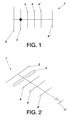
    • Figure 1. Depicts a flat view of the antenna of the invention.
    • Figure 2. Depicts an isometric representation of the antenna of the invention.
    • Figure 3. Depicts a duplexer configuration used with the antenna arrangement of the invention.
    • Figure 4. Depicts an optional duplexer configuration used with the antenna arrangement of the invention.
    DETAILED DESCRIPTION OF A PREFERRED EMBODIMENT
  • In the light of the abovementioned figures and following the adopted numbering, in figure 1 we can see the outline of the implementation of the antenna (1) arrangement object of the invention depicted in figure 1.
  • In a preferred embodiment of the object of the present invention the antenna (1) arrangement has a reflector element (2) working in working frequency F set at 900 MHz, with the reflector element (2), a driven element (3) and several director elements (4,4',4",4"') being arranged in parallel and comprised in the same plane. As shown in figure 2 the reflector element (2) is separated from the driven element (3), the driven element (3) from the director elements (4,4',4",4"'), all of them are separated by a distance which is frequency F dependent, being F the working frequency.
  • The antenna (1) arrangement detailed in this preferred embodiment works in different bands, namely: 900Mhz, 1800Mhz, 2100MHz and 2600MHz; in this preferred embodiment the reflector element (2) works in 900MHz, thus taking into account the relationship between working frequency F and length the sizes of the elements yield a relationship as follows:
    • Reflector element (2) length = (150/900) meters.
    • Driven element (3) length = 143/900 meters.
    • First director element (4) length = 138/1800 meters.
    • Second director element (4') length = 134/2100 meters.
    • Third director element (4") length = 129/2600 meters.
    • Additional director element (4"') length depends on any further working frequency.
  • In this preferred embodiment the above mentioned elements are arranged forming a flat multiband antenna (1) with all of the reflector element (2), the driven element (3) and the director elements (4,4',4",4"') are comprised in the same plane and prearranged as follows.
  • The reflector element (2) is allocated at the very end of the multiband antenna (1) and is separated from the next element of the antenna (1), the driven element (3), by a distance comprised between 37.5 F
    Figure imgb0023
    and 45 F
    Figure imgb0024
    metres (being F is the working frequency of the antenna); following the driven element (3) we find the first director element (4) arranged at a distance set between 37.5 F
    Figure imgb0025
    and 45 F
    Figure imgb0026
    metres (being F is the working frequency of the antenna) from the driven (3). Since in this embodiment the multiband antenna (1) works in several frequencies, the antenna (1) has more than one director element (4,4',4",4"'); consequently the second director element (4') is arranged next to the first director element (4) (in the opposite direction to that of the driven element (3)) at a distance set between 45 F
    Figure imgb0027
    and 75 F
    Figure imgb0028
    metres (being F is the working frequency). The remaining working frequency is handled by the third director element (4") which is set at a distance set between 60 F
    Figure imgb0029
    and 75 F
    Figure imgb0030
    metres (being F is the working frequency) from the second director element (4"). If needed, any additional director element (4"') is mounted separated from the third director element (4") at a distance of at least 75 F
    Figure imgb0031
    metres.
  • Another embodiment of the antenna (1) arrangement of the invention provides a solution for Adaptive Antenna Systems (AAS) using duplexers; wherein the transmission is done through a broadband dipole and the reception is splitted between different dipoles: each band through a different dipole.
  • In this embodiment we have the following transmission and reception frequencies:
    • TX: 2100MHz
    • RX: is 1920∼1980MHz
  • As earlier stated Wideband Adaptive Antenna Systems (AAS) with current antennas would have two transmission Tx bands and two reception Rx bands.
    • TX1:1800MHz
    • TX2:2100MHz
    • RX1:1710-1785MHz
    • RX2 (RX band of TX2) is 1920∼1980MHz
      • The duplexer is a 4-band filter as can be seen in Figure 1 c)
      • RX2 is in the middle of the TX1 and TX2
  • As a filter of RX2 has to reject the Tx signal from 2 TX (TX1 band and TX2 band), the difficulty is the double comparing to DUP of Single Band system. It is the same for TX1, a 1805∼1880MHz filter.
  • By implementing the antenna (1) arrangement object of the invention we have:
    • Dipol f1-f2:
      • TX1:1800MHz
      • TX2:2100MHz
      • RX1: 1710-1785MHz
    • Dipol f2:
      • RX2 (rx band of TX2) is 1920∼1980MHz
  • The RX2 band located in between the two TX bands is not received by dipol f1-f2 so duplexer is simplified as seen in figures 3 and 4.
  • The same concept applied to Adaptive Antenna Systems (AAS) could be applied for any other radio unit.

Claims (15)

  1. Antenna (1) arrangement comprising:
    - one driven element (3) connected to a transmission line,
    - one reflector element (2), arranged in a preceding position to that of the driven element (3), working at a working frequency F of the antenna (1),
    - at least one of the following director elements (4,4',4",4"'):
    - a first director element (4),
    - a second director element (4'),
    - a third director element (4"),
    - an additional director element (4"'),arranged in a following position in respect to that of the driven element (3), adapted to work at different frequencies, wherein one of the at least one director elements (4,4',4",4"') is adapted to act as active element exciting the driven element (3) when the reflector (2) works at a working frequency F of said at least one director element (4,4',4",4"').
  2. Antenna (1) arrangement according to claim 1 wherein the reflector element (2) and the driven element (3) are separated by a distance comprised in a range set between 37.5 F
    Figure imgb0032
    and 45 F
    Figure imgb0033
    metres wherein F is the working frequency.
  3. Antenna (1) arrangement according to claim 1 or 2 characterised by comprising a first director element (4) which is arranged closer to the driven element (3).
  4. Antenna (1) arrangement according to claim 3 wherein the driven element (3) and the first director element (4) are separated by a distance comprised in a range set between 37.5 F
    Figure imgb0034
    and 45 F
    Figure imgb0035
    metres wherein F is the working frequency.
  5. Antenna (1) arrangement according to any one of claims 1, 3 or 4 characterised by comprising a second director element (4') which is arranged following the first director element (4).
  6. Antenna (1) arrangement according to claim 5 wherein the second director element (4') is separated from the first director element (4) by a distance comprised in a range set between 45 F
    Figure imgb0036
    and 75 F
    Figure imgb0037
    metres wherein F is the working frequency.
  7. Antenna (1) arrangement according to any one of claims 1, 5 or 6 characterised by comprising a third director element (4") which is arranged following the second director (4').
  8. Antenna (1) arrangement according to claim 7 wherein the third director element (4") is separated from the second director element (4') by a distance comprised in a range set between 60 F
    Figure imgb0038
    and 75 F
    Figure imgb0039
    metres wherein F is the working frequency.
  9. Antenna (1) arrangement according to any one of claims 1, 7 or 8 characterised by comprising at least one additional director element (4"') following the third director element (4").
  10. Antenna (1) arrangement according to claim 9 wherein any one of the at least one additional director elements (4"') is separated from any other director elements (4,4',4",4") arranged in a preceding position by a distance set in 75 F
    Figure imgb0040
    metres wherein F is the working frequency.
  11. Antenna (1) arrangement according to any one of claims 1 to 10 wherein the length of the reflector element (2) is comprised in a range set between 148.5 F
    Figure imgb0041
    and 150 F
    Figure imgb0042
    metres wherein F is the working frequency.
  12. Antenna (1) arrangement according to any one of claims 1 to 11 wherein the length of the driven element (3) is comprised in a range set between 141.9 F
    Figure imgb0043
    and 143 F
    Figure imgb0044
    metres wherein F is the working frequency.
  13. Antenna (1) arrangement according to any one of claims 1 to 12 wherein the length of the first director element (4') is comprised in a range set between 138 F
    Figure imgb0045
    and 150 F
    Figure imgb0046
    metres wherein F is the working frequency.
  14. Antenna (1) arrangement according to any one of claims 1 to 13 wherein the at least one director element (4,4',4",4"'), the driven element (3) and the at least one director element (4,4',4",4"') are coplanar.
  15. Antenna (1) arrangement according to any one of claims 1 to 13 wherein the at least one director element (4,4',4",4"'), the driven element (3) and the at least one director element (4,4',4",4"') define a three dimensional structure.
EP10382279A 2010-10-25 2010-10-25 Antenna arrangement Withdrawn EP2445055A1 (en)

Priority Applications (2)

Application Number Priority Date Filing Date Title
EP10382279A EP2445055A1 (en) 2010-10-25 2010-10-25 Antenna arrangement
US13/280,511 US8803753B2 (en) 2010-10-25 2011-10-25 Antenna arrangement

Applications Claiming Priority (1)

Application Number Priority Date Filing Date Title
EP10382279A EP2445055A1 (en) 2010-10-25 2010-10-25 Antenna arrangement

Publications (1)

Publication Number Publication Date
EP2445055A1 true EP2445055A1 (en) 2012-04-25

Family

ID=43431127

Family Applications (1)

Application Number Title Priority Date Filing Date
EP10382279A Withdrawn EP2445055A1 (en) 2010-10-25 2010-10-25 Antenna arrangement

Country Status (2)

Country Link
US (1) US8803753B2 (en)
EP (1) EP2445055A1 (en)

Cited By (1)

* Cited by examiner, † Cited by third party
Publication number Priority date Publication date Assignee Title
US11056788B2 (en) * 2016-04-27 2021-07-06 Cisco Technology, Inc. Method of making a dual-band yagi-uda antenna array

Citations (4)

* Cited by examiner, † Cited by third party
Publication number Priority date Publication date Assignee Title
JP2000278037A (en) * 1999-03-25 2000-10-06 Tdk Corp Chip antenna
WO2005036694A2 (en) * 2003-10-02 2005-04-21 Emag Technologies, Inc. Antenna system embedded in a support structure for interrogating a tire sensor transponder
JP2006049945A (en) * 2004-07-30 2006-02-16 Maspro Denkoh Corp Yagi uda antenna system
KR200439899Y1 (en) * 2006-12-05 2008-05-13 (주)에이스안테나 The antenna system obtained by a combination Yagi antenna and log periodic antenna

Family Cites Families (4)

* Cited by examiner, † Cited by third party
Publication number Priority date Publication date Assignee Title
US4028709A (en) * 1975-09-10 1977-06-07 The United States Of America As Represented By The Field Operations Bureau Of The Federal Communications Commission Adjustable yagi antenna
US4218686A (en) * 1978-02-23 1980-08-19 Blonder-Tongue Laboratories, Inc. Yagi-type antennas and method
US6307524B1 (en) * 2000-01-18 2001-10-23 Core Technology, Inc. Yagi antenna having matching coaxial cable and driven element impedances
US7629938B1 (en) * 2006-07-24 2009-12-08 The United States Of America As Represented By The Secretary Of The Navy Open Yaggi antenna array

Patent Citations (4)

* Cited by examiner, † Cited by third party
Publication number Priority date Publication date Assignee Title
JP2000278037A (en) * 1999-03-25 2000-10-06 Tdk Corp Chip antenna
WO2005036694A2 (en) * 2003-10-02 2005-04-21 Emag Technologies, Inc. Antenna system embedded in a support structure for interrogating a tire sensor transponder
JP2006049945A (en) * 2004-07-30 2006-02-16 Maspro Denkoh Corp Yagi uda antenna system
KR200439899Y1 (en) * 2006-12-05 2008-05-13 (주)에이스안테나 The antenna system obtained by a combination Yagi antenna and log periodic antenna

Non-Patent Citations (1)

* Cited by examiner, † Cited by third party
Title
KARL ROTHAMMEL: "Antennenbuch", 1 January 1984, TELEKOSMOS-VERLAG FRANCKH'SCHE VERLAGSHANDLUNG, Stuttgart, Germany, ISBN: 3-440-04791-1, XP002617550 *

Cited By (1)

* Cited by examiner, † Cited by third party
Publication number Priority date Publication date Assignee Title
US11056788B2 (en) * 2016-04-27 2021-07-06 Cisco Technology, Inc. Method of making a dual-band yagi-uda antenna array

Also Published As

Publication number Publication date
US8803753B2 (en) 2014-08-12
US20120127052A1 (en) 2012-05-24

Similar Documents

Publication Publication Date Title
EP2041840B1 (en) Multiband antenna arrangement
US6943746B2 (en) Radio device and antenna structure
US8922447B2 (en) Smart antenna
CN101002360B (en) System and method for impedance matching an antenna to sub-bands in a communication band
US20050179607A1 (en) Method and apparatus for dynamically selecting the best antennas/mode ports for transmission and reception
EP2038962B1 (en) Multiband multimode compact antenna system
CN104981939A (en) An antenna arrangement and a base station
EP2617098B1 (en) Antenna for diversity operation
EP1770874A1 (en) Antenna system for a radiocommunication station, and radiocommunication station having such antenna system
EP3574552B1 (en) Method and apparatus for multi-feed multi-band mimo antenna system
EP2999046A1 (en) Multi-antenna system and mobile terminal
CN105009361A (en) An antenna arrangement and a base station
US9225381B2 (en) Tunable quality factor
CN102576936A (en) Methods for reducing near-field radiation and specific absorption rate (SAR) values in communications devices
EP3683890B1 (en) Electronic device and antenna structure thereof
US9478860B2 (en) Multiband antenna
EP3622581B1 (en) A broadband antenna
US20060119529A1 (en) Ultra wideband antenna
US8803753B2 (en) Antenna arrangement
US20160072195A1 (en) Diversity antenna arrangement for WLAN, and WLAN communication unit having such a diversity antenna arrangement, and device having such a WLAN communication unit
CN107591614B (en) High-gain omnidirectional array antenna
EP3918663B1 (en) Dual port antenna structure
CN106992802B (en) Signal receiving and transmitting device for user terminal, user terminal and signal transmission method
CN102738566A (en) Miniaturized three-band satellite communication antenna
CN212908111U (en) Multi-band antenna integration structure

Legal Events

Date Code Title Description
AK Designated contracting states

Kind code of ref document: A1

Designated state(s): AL AT BE BG CH CY CZ DE DK EE ES FI FR GB GR HR HU IE IS IT LI LT LU LV MC MK MT NL NO PL PT RO RS SE SI SK SM TR

AX Request for extension of the european patent

Extension state: BA ME

PUAI Public reference made under article 153(3) epc to a published international application that has entered the european phase

Free format text: ORIGINAL CODE: 0009012

STAA Information on the status of an ep patent application or granted ep patent

Free format text: STATUS: THE APPLICATION IS DEEMED TO BE WITHDRAWN

18D Application deemed to be withdrawn

Effective date: 20121026