EP2444778A2 - Display device, display method, display program, and computer readable medium - Google Patents
Display device, display method, display program, and computer readable medium Download PDFInfo
- Publication number
- EP2444778A2 EP2444778A2 EP11184878A EP11184878A EP2444778A2 EP 2444778 A2 EP2444778 A2 EP 2444778A2 EP 11184878 A EP11184878 A EP 11184878A EP 11184878 A EP11184878 A EP 11184878A EP 2444778 A2 EP2444778 A2 EP 2444778A2
- Authority
- EP
- European Patent Office
- Prior art keywords
- display
- image
- finger
- user
- detected
- Prior art date
- Legal status (The legal status is an assumption and is not a legal conclusion. Google has not performed a legal analysis and makes no representation as to the accuracy of the status listed.)
- Withdrawn
Links
Images


Classifications
-
- G—PHYSICS
- G01—MEASURING; TESTING
- G01C—MEASURING DISTANCES, LEVELS OR BEARINGS; SURVEYING; NAVIGATION; GYROSCOPIC INSTRUMENTS; PHOTOGRAMMETRY OR VIDEOGRAMMETRY
- G01C21/00—Navigation; Navigational instruments not provided for in groups G01C1/00 - G01C19/00
- G01C21/26—Navigation; Navigational instruments not provided for in groups G01C1/00 - G01C19/00 specially adapted for navigation in a road network
- G01C21/34—Route searching; Route guidance
- G01C21/36—Input/output arrangements for on-board computers
- G01C21/3664—Details of the user input interface, e.g. buttons, knobs or sliders, including those provided on a touch screen; remote controllers; input using gestures
-
- G—PHYSICS
- G06—COMPUTING; CALCULATING OR COUNTING
- G06F—ELECTRIC DIGITAL DATA PROCESSING
- G06F3/00—Input arrangements for transferring data to be processed into a form capable of being handled by the computer; Output arrangements for transferring data from processing unit to output unit, e.g. interface arrangements
- G06F3/01—Input arrangements or combined input and output arrangements for interaction between user and computer
- G06F3/048—Interaction techniques based on graphical user interfaces [GUI]
- G06F3/0484—Interaction techniques based on graphical user interfaces [GUI] for the control of specific functions or operations, e.g. selecting or manipulating an object, an image or a displayed text element, setting a parameter value or selecting a range
- G06F3/0485—Scrolling or panning
-
- G—PHYSICS
- G06—COMPUTING; CALCULATING OR COUNTING
- G06F—ELECTRIC DIGITAL DATA PROCESSING
- G06F3/00—Input arrangements for transferring data to be processed into a form capable of being handled by the computer; Output arrangements for transferring data from processing unit to output unit, e.g. interface arrangements
- G06F3/01—Input arrangements or combined input and output arrangements for interaction between user and computer
- G06F3/048—Interaction techniques based on graphical user interfaces [GUI]
- G06F3/0487—Interaction techniques based on graphical user interfaces [GUI] using specific features provided by the input device, e.g. functions controlled by the rotation of a mouse with dual sensing arrangements, or of the nature of the input device, e.g. tap gestures based on pressure sensed by a digitiser
- G06F3/0488—Interaction techniques based on graphical user interfaces [GUI] using specific features provided by the input device, e.g. functions controlled by the rotation of a mouse with dual sensing arrangements, or of the nature of the input device, e.g. tap gestures based on pressure sensed by a digitiser using a touch-screen or digitiser, e.g. input of commands through traced gestures
Definitions
- the present invention relates to a display device, a display method, a display program, and a computer readable medium.
- a map shown on a display is scrolled up, down, left, or right, and a list shown on the display is scrolled in a specific direction.
- Operational input for thus scrolling information shown on the display includes operational input using a touch panel or a joystick, for example.
- a proposed scroll control device of a screen performs a control that scrolls a display screen by a vector based on a change vector of an input coordinate while coordinate input is performed by a coordinate input part using a touch panel, and scrolls the display screen when the coordinate input is stopped by a vector based on a change vector of an input coordinate just before coordinate input is stopped.
- the image display position can be updated so as to track in a delayed manner the movement of the user's finger contacting a touch panel. It is thus possible to suppress continued hiding of a specific portion of the displayed image by the user's finger, and improve visibility.
- the degree of delay with which the map movement tracks the movement of the user's finger can be adjusted depending on the scale of the map, and visibility further improved. For example, when displaying a wide area map with a high density of display information such as location names and facility names, the map can be moved relatively slowly with respect to the movement of the user's finger. Conversely, when displaying a detailed map with a low density of display information such as location names and facility names, the map can be moved relatively quickly with respect to the movement of the user's finger.
- FIG 1 is a block diagram that illustrates the display device according to a first embodiment.
- a display device 1 includes a touch panel 10, a display 20, a control unit 30, and a data storage unit 40.
- the touch panel 10 is an input unit that, through pressure from a user's finger F or the like, accepts various types of operations that include operational input for moving an image displayed on the display 20.
- the touch panel 10 is formed transparent or semi-transparent and provided overlapping with a display screen of the display 20 on the front of the display 20.
- a commonly known touch panel that includes an operation position detection unit based on a resistive film, capacitance, or other system may be used as the touch panel 10.
- the display 20 is a display unit that displays images based on a control of the control unit 30.
- the specific constitution of the display 20 may take on any form, and a flat panel display such as a commonly known liquid crystal display or organic EL display may be used.
- the control unit 30 controls the display device 1.
- the control unit 30 is a computer configured to include a CPU, various programs that are interpreted and executed in the CPU (including an OS and other basic control programs, and application programs that are activated in the OS to carry out specific functions), and an internal memory such as a RAM for storing the programs and various data.
- the display program according to the first embodiment is installed in the display device 1 through any storage medium or network, and configures various portions of the control unit 30 in substance.
- the control unit 30 includes a position detection unit 31 and a display control unit 32 in terms of functional concept.
- the position detection unit 31 detects the position of the user's finger F contacting the touch panel 10 in a predetermined detection cycle.
- the display control unit 32 updates the display position of information on the display 20 in a predetermined display cycle. The processes executed by the various portions of the control unit 30 will be described in detail later.
- the data storage unit 40 is a storage unit that stores programs and various data required for operation of the display device 1, and has a configuration that uses a magnetic storage medium such as a hard disk (not shown) as an external memory device, for example.
- a magnetic storage medium such as a hard disk (not shown)
- any other storage mediums including a semiconductor storage medium such as a flash memory or an optical storage medium such as a DVD or Blu-ray disc, can be used in place of or in combination with the hard disk.
- the data storage unit 40 includes a map information database 41. (Note that database will be abbreviated to "DB” below.)
- the map information DB 41 is a map information storage unit that stores map information.
- the "map information" is configured to include link data (e.g., link numbers, connection node numbers, road coordinates, road types, number of lanes, travel restrictions), node data (node numbers and coordinates), feature data (e.g., traffic signals, road signs, guard rails, buildings), target feature data (e.g., intersections, stop lines, railroad crossings, curves, ETC toll booths, expressway exits), facility data (e.g., facility locations and facility types), topography data, and map display data for displaying a map on the display 20.
- link data e.g., link numbers, connection node numbers, road coordinates, road types, number of lanes, travel restrictions
- node data node numbers and coordinates
- feature data e.g., traffic signals, road signs, guard rails, buildings
- target feature data e.g., intersections, stop lines, railroad crossings, curves, ETC toll booths,
- FIG 2 is a flowchart of the display control process (steps in the descriptions of each process below are abbreviated to "S").
- the display control process is activated, for example, after the display device 1 is powered on and an image such as a map or a list is displayed on the display 20.
- the position detection unit 31 stands by until it is determined on the basis of an output from the touch panel 10 that the user's finger F contacted the touch panel 10 (SA1: No). If the user's finger F contacted the touch panel 10 (SA1: Yes), the position detection unit 31 specifies a position on the image corresponding to a position at which the user's finger F starts contacting the touch panel 10 (referred to as a "contact start position” below as appropriate) (SA2).
- SA2 a position on the image corresponding to the contact start position
- the "position on the image corresponding to the contact start position” refers to the coordinates of the position of the user's finger F when the user starts contacting the touch panel 10 in a coordinate system that moves along with the image.
- the position detection unit 31 stands by until a timing is reached at which to update the display position of the image displayed on the display 20 (SA3: No). If the timing to update the image display position is reached (SA3: Yes), the position detection unit 31 detects on the basis of an output from the touch panel 10 that a position at which the user's finger F (referred to as a "finger position" below as appropriate) is contacting the touch panel 10 (SA4). Note that the timing to update the image display position may be reached in a predetermined cycle (e.g., 20 milliseconds).
- the display control unit 32 specifies a position on the display 20 that corresponds to the position on the image corresponding to the contact start position of the user's finger F specified at SA2 (referred to as a "position on the image displayed on the display 20" below as appropriate), and a position on the display 20 that corresponds to the detected position of the user's finger F detected by the position detection unit 31 at SA4 (referred to as a "finger position on the display 20" below as appropriate) (SA5).
- the "position on the display 20 that corresponds to the position on the image corresponding to the contact start position of the user's finger F specified at SA2" refers to, for example, the coordinates of the position on the image corresponding to the contact start position of the user's finger F as specified at SA2 in a coordinate system whose origin is the upper left end of the display 20.
- the "position on the display 20 that corresponds to the detected position of the user's finger F detected by the position detection unit 31 at SA4" refers to, for example, the coordinates of the finger position detected by the position detection unit 31 at SA4 in a coordinate system whose origin is the upper left end of the display 20.
- the display control unit 32 calculates a moving amount of the image display position (SA6). Specifically, the display control unit 32 calculates the moving amount of the image display position as a value that multiples a distance between the position on the image displayed on the display 20 and the finger position on the display 20 specified at SA5 by a predetermined coefficient (preferably positive) of less than one (e.g., 0.4).
- the display control unit 32 may set the predetermined coefficient to a value that varies depending on a scale of the map. For example, a formula that calculates the predetermined coefficient from the map scale may be stored in advance in the data storage unit 40, and the formula used by the display control unit 32 to calculate the predetermined coefficient from the map scale. In such case, for example, a larger map scale (that is, a wider map area displayed on the display 20) results in a smaller predetermined coefficient.
- a larger map scale that is, a wider map area displayed on the display 20
- the moving amount within the map can be decreased.
- the moving amount within the map can be increased.
- the map when displaying a wide area map with a high density of display information such as location names and facility names, the map can be moved relatively slowly with respect to the movement of the user's finger F. Conversely, when displaying a detailed map with a low density of display information such as location names and facility names, the map can be moved relatively quickly with respect to the movement of the user's finger F.
- the display control unit 32 calculates the moving amount of the image display position based on a distance of a component of the specific direction between the position on the image displayed on the display 20 and the finger position on the display 20. In such case, the display control unit 32 calculates the moving amount of the image display position as a value that multiples the distance of the component of the specific direction between the position on the image displayed on the display 20 and the finger position on the display 20 by the predetermined coefficient.
- the display control unit 32 determines whether the moving amount calculated at SA6 is greater than a minimum moving amount (SA7).
- SA7 a minimum moving amount
- a minimum unit that an image displayed on the display 20 can be moved e.g., one dot
- SA7 a minimum unit that an image displayed on the display 20 can be moved
- the minimum moving amount may be a display width or a display height per list item.
- the minimum moving amount is the display width per list item when the list items are listed in a display width direction
- the minimum moving amount is the display height per list item when the list items are listed in a display height direction.
- the display control unit 32 updates the image display position by moving the image display position in a direction heading from the position on the image displayed on the display 20 toward the finger position on the display 20 by the moving amount calculated at SA6 (SA8). Thereafter, the control unit 30 repeats the processing from SA3 to SA8. Thus, the display position of the image displayed on the display 20 is updated in a predetermined cycle (e.g., 20 milliseconds) by the display control unit 32.
- a predetermined cycle e.g., 20 milliseconds
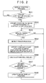
- FIGS. 3A and 3B are diagrams that illustrate an example of a map displayed on the display 20, wherein FIG 3A is a diagram that shows the user's finger F starting to contact the touch panel 10, and FIG 3B is a diagram that shows the user's finger F moving while in contact with the touch panel 10 (performing a so-called dragging operation).
- the map display position is sequentially updated in a direction (indicated by an arrow in FIG 3B ) that heads from a position (A in FIGS. 3A and 3B ) on the image displayed on the display 20 toward a finger position (B in FIGS. 3A and 3B ) on the display 20.
- the map display position is updated so as to track in a delayed manner the movement of the user's finger F contacting the touch panel 10.
- an icon hidden under the user's finger F when the user's finger F starts to contact the touch panel 10 (a "T" icon in FIG 3A ) can be made visible by delayed tracking of the movement of the user's finger F (a state shown in FIG 3B ).
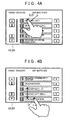
- FIGS. 4A and 4B are diagrams that illustrate an example of a list formed of a plurality of items displayed on the display 20, wherein FIG 4A is a diagram that shows the user's finger F starting to contact the touch panel 10, and FIG 4B is a diagram that shows the user's finger F moving while in contact with the touch panel 10 (performing a so-called dragging operation).
- the list display position is sequentially updated in line with a component of the specific direction (indicated by an arrow in FIG 4B ) in a direction that heads from a position (C in FIGS. 4A and 4B ) on the image displayed on the display 20 toward a finger position (D in FIGS.
- the list display position is updated so as to track in a delayed manner the specific direction component of the movement of the user's finger F contacting the touch panel 10.
- a button hidden under the user's finger F when the user's finger F starts to contact the touch panel 10 an "Okazaki City" button in FIG 4A
- can be made visible by delayed tracking of the movement of the user's finger F (a state shown in FIG 4B ).
- the position detection unit 31 monitors on the basis of an output from the touch panel 10 whether the user's finger F lifts from the touch panel 10. If the user's finger F lifts from the touch panel 10, the control unit 30 returns at that point to SA1
- the moving amount of the image display position is a value that multiplies the distance between the position on the image displayed on the display 20 and the finger position on the display 20 by the predetermined coefficient of less than one.
- the image display position is updated in the predetermined cycle by moving the image display position in a direction that heads from the position on the image displayed on the display 20 toward the finger position on the display 20. Therefore, the image display position can be updated so as to track in a delayed manner the movement of the user's finger F contacting the touch panel 10. It is thus possible to suppress continued hiding of a specific portion of the displayed image by the user's finger F, and improve visibility.
- the display control unit 32 calculates the moving amount of the image display position based on the distance of the component of the specific direction between the position on the image displayed on the display 20 and the finger position on the display 20.
- the display control unit 32 calculates the moving amount of the image display position based on the distance of the component of the specific direction between the position on the image displayed on the display 20 and the finger position on the display 20.
- the minimum moving amount is the display width or the display height per list item. It is thus possible to prevent the movement of the list stopping with list items cut off at end portions of the display 20.
- the display control unit 32 sets the predetermined coefficient to a value that varies depending on the scale of the map. Therefore, the degree of delay with which the map movement tracks the movement of the user's finger F can be adjusted depending on the scale of the map, and visibility further improved. For example, when displaying a wide area map with a high density of display information such as location names and facility names, the map can be moved relatively slowly with respect to the movement of the user's finger F. Conversely, when displaying a detailed map with a low density of display information such as location names and facility names, the map can be moved relatively quickly with respect to the movement of the user's finger F.
- the display control unit 32 each time the position detection unit 31 detects the finger position (SA4), the display control unit 32 updates the display position of the image displayed on the display 20 (SA8).
- the finger position detection cycle and the display cycle for updating the image display position may use different values.
Abstract
Description
- The present invention relates to a display device, a display method, a display program, and a computer readable medium.
- In past car navigation devices and the like, a map shown on a display is scrolled up, down, left, or right, and a list shown on the display is scrolled in a specific direction. Operational input for thus scrolling information shown on the display includes operational input using a touch panel or a joystick, for example.
- A proposed scroll control device of a screen (
JP-A-H10-161628 - However, according to the device of the related art described above, when the user moves his or her finger on the touch panel (performs a so-called dragging operation) to scroll an image such as a map or the like, the image is scrolled so as to match the finger movement. Therefore, the image displayed directly under the finger may remain constantly hidden under the finger and have poor visibility.
- It is an object of the present invention in the light of the foregoing to improve the scrolling characteristics. This object is achieved by a display device according to claim 1, a display method according to claim 5, a display program according to claim 9, and a computer readable medium according to
claim 10. Suppressing continued hiding of a specific portion of a displayed image by a finger, and improved visibility is enabled. Further developments are given in the dependent claims. A new reaction to the device to a command input by a user is disclosed. - According to a first aspect, the image display position can be updated so as to track in a delayed manner the movement of the user's finger contacting a touch panel. It is thus possible to suppress continued hiding of a specific portion of the displayed image by the user's finger, and improve visibility.
- According to a second aspect, even if the image is scrolled in only the specific direction, it is possible to suppress continued hiding of a specific portion of the displayed image by the user's finger, and improve visibility.
- According to a third aspect, it is possible to prevent the movement of the list stopping with list items cut off at end portions of a display unit.
- According to a fourth aspect, the degree of delay with which the map movement tracks the movement of the user's finger can be adjusted depending on the scale of the map, and visibility further improved. For example, when displaying a wide area map with a high density of display information such as location names and facility names, the map can be moved relatively slowly with respect to the movement of the user's finger. Conversely, when displaying a detailed map with a low density of display information such as location names and facility names, the map can be moved relatively quickly with respect to the movement of the user's finger.
- Further features follow from the description of embodiments referring to the drawings, from which:
-
FIG 1 is a block diagram that illustrates a display device according to an embodiment; -
FIG 2 is a flowchart of a display control process; -
FIGS. 3A and 3B are diagrams that illustrate an example of a map displayed on a display, whereinFIG 3A is a diagram that shows a user's finger starting to contact a touch panel, andFIG 3B is a diagram that shows the user's finger moving while in contact with the touch panel; and -
FIGS. 4A and 4B are diagrams that illustrate an example of a list formed of a plurality of items displayed on a display, whereinFIG 4A is a diagram that shows a user's finger starting to contact a touch panel, andFIG 4B is a diagram that shows the user's finger moving while in contact with the touch panel. - Hereinafter, an embodiment of a display device, a display method, a display program, and a computer readable medium will be described in detail with reference to the drawings. However, the present invention is not limited to such an embodiment.
- First, the constitution of the display device according to an embodiment will be described.
FIG 1 is a block diagram that illustrates the display device according to a first embodiment. As shown inFIG 1 , a display device 1 includes atouch panel 10, adisplay 20, acontrol unit 30, and adata storage unit 40. - The
touch panel 10 is an input unit that, through pressure from a user's finger F or the like, accepts various types of operations that include operational input for moving an image displayed on thedisplay 20. Thetouch panel 10 is formed transparent or semi-transparent and provided overlapping with a display screen of thedisplay 20 on the front of thedisplay 20. A commonly known touch panel that includes an operation position detection unit based on a resistive film, capacitance, or other system may be used as thetouch panel 10. - The
display 20 is a display unit that displays images based on a control of thecontrol unit 30. Note that the specific constitution of thedisplay 20 may take on any form, and a flat panel display such as a commonly known liquid crystal display or organic EL display may be used. - The
control unit 30 controls the display device 1. Specifically, thecontrol unit 30 is a computer configured to include a CPU, various programs that are interpreted and executed in the CPU (including an OS and other basic control programs, and application programs that are activated in the OS to carry out specific functions), and an internal memory such as a RAM for storing the programs and various data. In particular, the display program according to the first embodiment is installed in the display device 1 through any storage medium or network, and configures various portions of thecontrol unit 30 in substance. - The
control unit 30 includes aposition detection unit 31 and adisplay control unit 32 in terms of functional concept. Theposition detection unit 31 detects the position of the user's finger F contacting thetouch panel 10 in a predetermined detection cycle. Thedisplay control unit 32 updates the display position of information on thedisplay 20 in a predetermined display cycle. The processes executed by the various portions of thecontrol unit 30 will be described in detail later. - The
data storage unit 40 is a storage unit that stores programs and various data required for operation of the display device 1, and has a configuration that uses a magnetic storage medium such as a hard disk (not shown) as an external memory device, for example. However, any other storage mediums, including a semiconductor storage medium such as a flash memory or an optical storage medium such as a DVD or Blu-ray disc, can be used in place of or in combination with the hard disk. - The
data storage unit 40 includes amap information database 41. (Note that database will be abbreviated to "DB" below.) - The
map information DB 41 is a map information storage unit that stores map information. The "map information" is configured to include link data (e.g., link numbers, connection node numbers, road coordinates, road types, number of lanes, travel restrictions), node data (node numbers and coordinates), feature data (e.g., traffic signals, road signs, guard rails, buildings), target feature data (e.g., intersections, stop lines, railroad crossings, curves, ETC toll booths, expressway exits), facility data (e.g., facility locations and facility types), topography data, and map display data for displaying a map on thedisplay 20. - Next, a display control process executed by the display device 1 thus configured will be described.
FIG 2 is a flowchart of the display control process (steps in the descriptions of each process below are abbreviated to "S"). The display control process is activated, for example, after the display device 1 is powered on and an image such as a map or a list is displayed on thedisplay 20. - As shown in
FIG 2 , once the display control process is started, theposition detection unit 31 stands by until it is determined on the basis of an output from thetouch panel 10 that the user's finger F contacted the touch panel 10 (SA1: No). If the user's finger F contacted the touch panel 10 (SA1: Yes), theposition detection unit 31 specifies a position on the image corresponding to a position at which the user's finger F starts contacting the touch panel 10 (referred to as a "contact start position" below as appropriate) (SA2). Here, the "position on the image corresponding to the contact start position" refers to the coordinates of the position of the user's finger F when the user starts contacting thetouch panel 10 in a coordinate system that moves along with the image. - Next, the
position detection unit 31 stands by until a timing is reached at which to update the display position of the image displayed on the display 20 (SA3: No). If the timing to update the image display position is reached (SA3: Yes), theposition detection unit 31 detects on the basis of an output from thetouch panel 10 that a position at which the user's finger F (referred to as a "finger position" below as appropriate) is contacting the touch panel 10 (SA4). Note that the timing to update the image display position may be reached in a predetermined cycle (e.g., 20 milliseconds). - Next, the
display control unit 32 specifies a position on thedisplay 20 that corresponds to the position on the image corresponding to the contact start position of the user's finger F specified at SA2 (referred to as a "position on the image displayed on thedisplay 20" below as appropriate), and a position on thedisplay 20 that corresponds to the detected position of the user's finger F detected by theposition detection unit 31 at SA4 (referred to as a "finger position on thedisplay 20" below as appropriate) (SA5). Here, the "position on thedisplay 20 that corresponds to the position on the image corresponding to the contact start position of the user's finger F specified at SA2" refers to, for example, the coordinates of the position on the image corresponding to the contact start position of the user's finger F as specified at SA2 in a coordinate system whose origin is the upper left end of thedisplay 20. In addition, the "position on thedisplay 20 that corresponds to the detected position of the user's finger F detected by theposition detection unit 31 at SA4" refers to, for example, the coordinates of the finger position detected by theposition detection unit 31 at SA4 in a coordinate system whose origin is the upper left end of thedisplay 20. - Next, the
display control unit 32 calculates a moving amount of the image display position (SA6). Specifically, thedisplay control unit 32 calculates the moving amount of the image display position as a value that multiples a distance between the position on the image displayed on thedisplay 20 and the finger position on thedisplay 20 specified at SA5 by a predetermined coefficient (preferably positive) of less than one (e.g., 0.4). - Note that, if the image displayed on the
display 20 is a map, thedisplay control unit 32 may set the predetermined coefficient to a value that varies depending on a scale of the map. For example, a formula that calculates the predetermined coefficient from the map scale may be stored in advance in thedata storage unit 40, and the formula used by thedisplay control unit 32 to calculate the predetermined coefficient from the map scale. In such case, for example, a larger map scale (that is, a wider map area displayed on the display 20) results in a smaller predetermined coefficient. Thus, if the map displayed on thedisplay 20 is a wide area map, the moving amount within the map can be decreased. Conversely, if the map displayed on thedisplay 20 is a detail map, the moving amount within the map can be increased. Thus, when displaying a wide area map with a high density of display information such as location names and facility names, the map can be moved relatively slowly with respect to the movement of the user's finger F. Conversely, when displaying a detailed map with a low density of display information such as location names and facility names, the map can be moved relatively quickly with respect to the movement of the user's finger F. - In addition, if a moving direction of the image display position is limited by the
display control unit 32 to a specific direction (e.g., a list formed of a plurality of items is displayed on thedisplay 20, and the moving direction of the image display position is limited to a listing direction of the list items), thedisplay control unit 32 calculates the moving amount of the image display position based on a distance of a component of the specific direction between the position on the image displayed on thedisplay 20 and the finger position on thedisplay 20. In such case, thedisplay control unit 32 calculates the moving amount of the image display position as a value that multiples the distance of the component of the specific direction between the position on the image displayed on thedisplay 20 and the finger position on thedisplay 20 by the predetermined coefficient. - Next, the
display control unit 32 determines whether the moving amount calculated at SA6 is greater than a minimum moving amount (SA7). As the minimum moving amount, a minimum unit that an image displayed on thedisplay 20 can be moved (e.g., one dot) may be used, for example. - If the image displayed on the
display 20 is a list formed of a plurality of items, the minimum moving amount may be a display width or a display height per list item. In such case, the minimum moving amount is the display width per list item when the list items are listed in a display width direction, and the minimum moving amount is the display height per list item when the list items are listed in a display height direction. - If the determination result at SA7 is that the moving amount calculated at SA6 is not greater than the minimum moving amount (is equal to or less than the minimum moving amount) (SA7: No), the
control unit 30 returns to SA3. - However, if the determination result at SA7 is that the moving amount calculated at SA6 is greater than the minimum moving amount (SA7: Yes), the
display control unit 32 updates the image display position by moving the image display position in a direction heading from the position on the image displayed on thedisplay 20 toward the finger position on thedisplay 20 by the moving amount calculated at SA6 (SA8). Thereafter, thecontrol unit 30 repeats the processing from SA3 to SA8. Thus, the display position of the image displayed on thedisplay 20 is updated in a predetermined cycle (e.g., 20 milliseconds) by thedisplay control unit 32. -
FIGS. 3A and 3B are diagrams that illustrate an example of a map displayed on thedisplay 20, whereinFIG 3A is a diagram that shows the user's finger F starting to contact thetouch panel 10, andFIG 3B is a diagram that shows the user's finger F moving while in contact with the touch panel 10 (performing a so-called dragging operation). Based on thedisplay control unit 32 updating the map display position at SA8 inFIG 2 , the map display position is sequentially updated in a direction (indicated by an arrow inFIG 3B ) that heads from a position (A inFIGS. 3A and 3B ) on the image displayed on thedisplay 20 toward a finger position (B inFIGS. 3A and 3B ) on thedisplay 20. That is, as shown inFIG 3B , the map display position is updated so as to track in a delayed manner the movement of the user's finger F contacting thetouch panel 10. In the example ofFIGS. 3A and 3B , an icon hidden under the user's finger F when the user's finger F starts to contact the touch panel 10 (a "T" icon inFIG 3A ) can be made visible by delayed tracking of the movement of the user's finger F (a state shown inFIG 3B ). -
FIGS. 4A and 4B are diagrams that illustrate an example of a list formed of a plurality of items displayed on thedisplay 20, whereinFIG 4A is a diagram that shows the user's finger F starting to contact thetouch panel 10, andFIG 4B is a diagram that shows the user's finger F moving while in contact with the touch panel 10 (performing a so-called dragging operation). Based on thedisplay control unit 32 updating the map display position at SA8 inFIG 2 , the list display position is sequentially updated in line with a component of the specific direction (indicated by an arrow inFIG 4B ) in a direction that heads from a position (C inFIGS. 4A and 4B ) on the image displayed on thedisplay 20 toward a finger position (D inFIGS. 4A and 4B ) on thedisplay 20. That is, as shown inFIG 4B , the list display position is updated so as to track in a delayed manner the specific direction component of the movement of the user's finger F contacting thetouch panel 10. In the example ofFIGS. 4A and 4B , a button hidden under the user's finger F when the user's finger F starts to contact the touch panel 10 (an "Okazaki City" button inFIG 4A ) can be made visible by delayed tracking of the movement of the user's finger F (a state shown inFIG 4B ). - Note that, parallel to the processing from SA3 to SA8 in
FIG 2 , theposition detection unit 31 monitors on the basis of an output from thetouch panel 10 whether the user's finger F lifts from thetouch panel 10. If the user's finger F lifts from thetouch panel 10, thecontrol unit 30 returns at that point to SA1 - According to the present embodiment described above, the moving amount of the image display position is a value that multiplies the distance between the position on the image displayed on the
display 20 and the finger position on thedisplay 20 by the predetermined coefficient of less than one. Until the moving amount is equal to or less than the minimum moving amount, the image display position is updated in the predetermined cycle by moving the image display position in a direction that heads from the position on the image displayed on thedisplay 20 toward the finger position on thedisplay 20. Therefore, the image display position can be updated so as to track in a delayed manner the movement of the user's finger F contacting thetouch panel 10. It is thus possible to suppress continued hiding of a specific portion of the displayed image by the user's finger F, and improve visibility. - In addition, if the moving direction of the image display position is limited by the
display control unit 32 to a specific direction, thedisplay control unit 32 calculates the moving amount of the image display position based on the distance of the component of the specific direction between the position on the image displayed on thedisplay 20 and the finger position on thedisplay 20. Thus, even if the image is scrolled in only the specific direction, it is possible to suppress continued hiding of a specific portion of the displayed image by the user's finger F, and improve visibility. - In addition, if the image is a list formed of a plurality of items, the minimum moving amount is the display width or the display height per list item. It is thus possible to prevent the movement of the list stopping with list items cut off at end portions of the
display 20. - If the image is a map, the
display control unit 32 sets the predetermined coefficient to a value that varies depending on the scale of the map. Therefore, the degree of delay with which the map movement tracks the movement of the user's finger F can be adjusted depending on the scale of the map, and visibility further improved. For example, when displaying a wide area map with a high density of display information such as location names and facility names, the map can be moved relatively slowly with respect to the movement of the user's finger F. Conversely, when displaying a detailed map with a low density of display information such as location names and facility names, the map can be moved relatively quickly with respect to the movement of the user's finger F. - An embodiment of the present invention was explained above. However, the specific configuration and units for implementing the present invention may be modified and improved in any manner or form within the scope of the technical ideas of the present invention as set forth in the claims thereof. Examples of such modifications are explained below.
- The problems to be solved by the present invention and the effects of the present invention are not limited to the content described above and may vary depending on the environment in which the present invention is practiced and the detailed configuration thereof. The above problems may be only partially solved, and the above effects only partially achieved.
- According to the embodiment described above, as an example, in the display control process in
FIG 2 , each time theposition detection unit 31 detects the finger position (SA4), thedisplay control unit 32 updates the display position of the image displayed on the display 20 (SA8). However, the finger position detection cycle and the display cycle for updating the image display position may use different values. - It is explicitly stated that all features disclosed in the description and/or the claims are intended to be disclosed separately and independently from each other for the purpose of original disclosure as well as for the purpose of restricting the claimed invention independent of the composition of the features in the embodiments and/or the claims. It is explicitly stated that all value ranges or indications of groups of entities disclose every possible intermediated value or intermediate entity for the purpose of original disclosure as well as for the purpose of restricting the claimed invention, in particular as limits of value ranges.
Claims (10)
- A display device (1), comprising:a display unit (20) that is adapted to display an image;a touch panel (10) that is provided on a front surface of the display unit (20);a position detection unit (31) that is adapted to detect a position (A,B; C, D) of a user's finger (F) contacting the touch panel (10); anda display control unit (32) that, using a value that multiplies a distance between a position (A; C) on the display unit (20) that corresponds to a position on the image corresponding to a contact start position of the user's finger (F) detected by the position detection unit (31) and a position on the display unit (20) that corresponds to a detected position (B; D) of the user's finger (F) detected by the position detection unit (31) by a predetermined coefficient of less than one as a moving amount of a display position of the image, is adapted to update the display position of the image in a direction moving from the position (A; C) on the display unit that corresponds to the position on the image corresponding to the contact start position toward the position (B; D) on the display unit (20) that corresponds to the detected position of the user's finger (F) detected by the position detection unit (31) in a predetermined cycle until the moving amount is equal to or less than a minimum moving amount.
- The display device (1) according to claim 1, wherein
the display control unit (32) is adapted to, if the moving direction of the display position of the image is limited to a specific direction by the display control unit (32), calculate the moving amount based on a distance of a component of the specific direction between the position (A; C) on the display unit (20) that corresponds to the position on the image corresponding to the contact start position and the position (B; D) on the display unit (20) that corresponds to the detected position of the user's finger (F) detected by the position detection unit (31). - The display device (1) according to claim 1 or 2, wherein
the image is a list formed of a plurality of items, and
the minimum moving amount is one of a display width and a display height per list item. - The display device (1) according to claim 1 or 2, wherein
the image is a map, and
the display control unit (32) is adapted to set the predetermined coefficient to a value that varies depending on a scale of the map. - A display method, comprising the steps of:displaying an image on a display unit (20);detecting a position (A, B; C, D) of a user's finger (F) contacting a touch panel (10) that is provided on a front surface of the display unit (20); andupdating, using a value that multiplies a distance between a position (A; C) on the display unit that corresponds to a position on the image corresponding to a contact start position of the user's finger (F) detected at the position detection step and a position (B; D) on the display unit (20) that corresponds to a detected position of the user's finger (F) detected at the position detection step by a predetermined coefficient of less than one as a moving amount of a display position of the image, the display position of the image in a direction moving from the position (A; C) on the display unit (20) that corresponds to the position on the image corresponding to the contact start position toward the position (B; D) on the display unit (20) that corresponds to the detected position of the user's finger (F) detected at the position detection step in a predetermined cycle until the moving amount is equal to or less than a minimum moving amount.
- The display method according to claim 5, comprising the step of:if the moving direction of the display position of the image is limited to a specific direction, calculating moving amount based on a distance of a component of the specific direction between the position (A; C) on the display unit (20) that corresponds to the position on the image corresponding to the contact start position and the position (B; D) on the display unit (20) that corresponds to the detected position of the user's finger (F) detected.
- The display method according to claim 5 or 6, wherein
the image is a list formed of a plurality of items, and
the minimum moving amount is one of a display width and a display height per list item. - The display method according to claim 5 or 6, wherein
the image is a map, the method comprising the step of:setting the predetermined coefficient to a value that varies depending on a scale of the map. - A display program comprising program code which, when run on a computer causes the computer to perform the steps of a method according to any of claims 5 to 8.
- A computer readable medium comprising computer readable instructions containing a program according to claim 9.
Applications Claiming Priority (1)
| Application Number | Priority Date | Filing Date | Title |
|---|---|---|---|
| JP2010239113A JP2012093860A (en) | 2010-10-25 | 2010-10-25 | Display device, display method and display program |
Publications (2)
| Publication Number | Publication Date |
|---|---|
| EP2444778A2 true EP2444778A2 (en) | 2012-04-25 |
| EP2444778A3 EP2444778A3 (en) | 2014-11-05 |
Family
ID=44872204
Family Applications (1)
| Application Number | Title | Priority Date | Filing Date |
|---|---|---|---|
| EP11184878.4A Withdrawn EP2444778A3 (en) | 2010-10-25 | 2011-10-12 | Display device, display method, display program, and computer readable medium |
Country Status (4)
| Country | Link |
|---|---|
| US (1) | US8830190B2 (en) |
| EP (1) | EP2444778A3 (en) |
| JP (1) | JP2012093860A (en) |
| CN (1) | CN102566891A (en) |
Cited By (1)
| Publication number | Priority date | Publication date | Assignee | Title |
|---|---|---|---|---|
| WO2016001730A1 (en) * | 2014-06-30 | 2016-01-07 | Toyota Jidosha Kabushiki Kaisha | Operation device and operation method |
Families Citing this family (5)
| Publication number | Priority date | Publication date | Assignee | Title |
|---|---|---|---|---|
| JP2012093860A (en) | 2010-10-25 | 2012-05-17 | Aisin Aw Co Ltd | Display device, display method and display program |
| JP2012093887A (en) * | 2010-10-26 | 2012-05-17 | Aisin Aw Co Ltd | Display device, display method and display program |
| DE102013000272A1 (en) * | 2013-01-09 | 2014-07-10 | Daimler Ag | A method of moving an image content displayed on a display device of a vehicle, a vehicle operating and display device, and a computer program product |
| DE102013006026A1 (en) * | 2013-04-08 | 2014-10-09 | Audi Ag | Orientation zoom in navigation maps when displayed on small screens |
| CN111078061B (en) * | 2019-12-04 | 2023-08-22 | 佳格科技(浙江)股份有限公司 | Infrared touch screen, control method and system thereof |
Citations (1)
| Publication number | Priority date | Publication date | Assignee | Title |
|---|---|---|---|---|
| JPH10161628A (en) | 1996-11-26 | 1998-06-19 | Sony Corp | Scroll control device of screen and scroll control method thereof |
Family Cites Families (23)
| Publication number | Priority date | Publication date | Assignee | Title |
|---|---|---|---|---|
| JPH083785B2 (en) * | 1987-02-24 | 1996-01-17 | 富士通株式会社 | Display scroll method |
| JP3624626B2 (en) * | 1997-05-28 | 2005-03-02 | ソニー株式会社 | Information processing apparatus and method, and recording medium |
| US6747680B1 (en) | 1999-12-13 | 2004-06-08 | Microsoft Corporation | Speed-dependent automatic zooming interface |
| US8479122B2 (en) * | 2004-07-30 | 2013-07-02 | Apple Inc. | Gestures for touch sensitive input devices |
| US7152210B1 (en) | 1999-10-20 | 2006-12-19 | Koninklijke Philips Electronics N.V. | Device and method of browsing an image collection |
| US7142205B2 (en) * | 2000-03-29 | 2006-11-28 | Autodesk, Inc. | Single gesture map navigation graphical user interface for a personal digital assistant |
| JP4518231B2 (en) | 2000-04-28 | 2010-08-04 | ソニー株式会社 | Portable information terminal device |
| US6690387B2 (en) | 2001-12-28 | 2004-02-10 | Koninklijke Philips Electronics N.V. | Touch-screen image scrolling system and method |
| JP3734815B2 (en) | 2003-12-10 | 2006-01-11 | 任天堂株式会社 | Portable game device and game program |
| US7786975B2 (en) | 2005-12-23 | 2010-08-31 | Apple Inc. | Continuous scrolling list with acceleration |
| JP4678534B2 (en) * | 2007-06-07 | 2011-04-27 | ソニー株式会社 | Navigation device and map scroll processing method |
| US8209635B2 (en) | 2007-12-20 | 2012-06-26 | Sony Mobile Communications Ab | System and method for dynamically changing a display |
| JP2009276819A (en) * | 2008-05-12 | 2009-11-26 | Fujitsu Ltd | Method for controlling pointing device, pointing device and computer program |
| JP4797045B2 (en) * | 2008-06-10 | 2011-10-19 | 株式会社コナミデジタルエンタテインメント | Item selection device, item selection method, and program |
| JP5461030B2 (en) * | 2009-03-02 | 2014-04-02 | アルパイン株式会社 | Input device |
| US8839155B2 (en) | 2009-03-16 | 2014-09-16 | Apple Inc. | Accelerated scrolling for a multifunction device |
| JP5282617B2 (en) | 2009-03-23 | 2013-09-04 | ソニー株式会社 | Information processing apparatus, information processing method, and information processing program |
| CN101593059B (en) * | 2009-06-25 | 2011-11-02 | 友达光电股份有限公司 | Touch panel, touch detection method thereof and display device with touch function |
| JP5457941B2 (en) | 2009-08-06 | 2014-04-02 | キヤノン株式会社 | Information processing apparatus and information processing apparatus control method |
| US8456297B2 (en) | 2010-01-06 | 2013-06-04 | Apple Inc. | Device, method, and graphical user interface for tracking movement on a map |
| US9417787B2 (en) | 2010-02-12 | 2016-08-16 | Microsoft Technology Licensing, Llc | Distortion effects to indicate location in a movable data collection |
| US9542091B2 (en) | 2010-06-04 | 2017-01-10 | Apple Inc. | Device, method, and graphical user interface for navigating through a user interface using a dynamic object selection indicator |
| JP2012093860A (en) | 2010-10-25 | 2012-05-17 | Aisin Aw Co Ltd | Display device, display method and display program |
-
2010
- 2010-10-25 JP JP2010239113A patent/JP2012093860A/en active Pending
-
2011
- 2011-10-09 CN CN2011103083106A patent/CN102566891A/en active Pending
- 2011-10-12 EP EP11184878.4A patent/EP2444778A3/en not_active Withdrawn
- 2011-10-12 US US13/271,758 patent/US8830190B2/en not_active Expired - Fee Related
Patent Citations (1)
| Publication number | Priority date | Publication date | Assignee | Title |
|---|---|---|---|---|
| JPH10161628A (en) | 1996-11-26 | 1998-06-19 | Sony Corp | Scroll control device of screen and scroll control method thereof |
Cited By (1)
| Publication number | Priority date | Publication date | Assignee | Title |
|---|---|---|---|---|
| WO2016001730A1 (en) * | 2014-06-30 | 2016-01-07 | Toyota Jidosha Kabushiki Kaisha | Operation device and operation method |
Also Published As
| Publication number | Publication date |
|---|---|
| US20120098770A1 (en) | 2012-04-26 |
| EP2444778A3 (en) | 2014-11-05 |
| JP2012093860A (en) | 2012-05-17 |
| US8830190B2 (en) | 2014-09-09 |
| CN102566891A (en) | 2012-07-11 |
Similar Documents
| Publication | Publication Date | Title |
|---|---|---|
| EP2447820A2 (en) | Display device, display method, display program, and computer readable medium | |
| EP2444778A2 (en) | Display device, display method, display program, and computer readable medium | |
| EP2505963A2 (en) | Display device, display method, and computer program product | |
| EP2444885B1 (en) | Image display device, image display method and corresponding computer program product | |
| US8599159B2 (en) | Touch panel type operation device, touch panel operation method, and computer program | |
| US10330488B2 (en) | Display method for a display system, display system and operating method for a navigation system of a vehicle | |
| KR102237363B1 (en) | Graphical interface and method for managing said graphical interface during the touch-selection of a displayed element | |
| JP2003254761A5 (en) | ||
| JP2015072534A (en) | Information processor, and information processing method and program | |
| US20080055257A1 (en) | Touch-Sensitive Interface Operating System | |
| JP5094525B2 (en) | Car navigation system | |
| US8942833B2 (en) | Display device with stepwise display scale control, stepwise control method of the display scale on a display device, and computer program for stepwise control of the display scale of a display device | |
| JP2005030800A (en) | Navigation apparatus and scrolling display method of map | |
| US20130100158A1 (en) | Display mapping modes for multi-pointer indirect input devices | |
| JP2012133245A (en) | Map display device, map display method, and computer program | |
| JP2012215648A (en) | Display device, display method and display program | |
| US20130100018A1 (en) | Acceleration-based interaction for multi-pointer indirect input devices | |
| JP2011053101A (en) | Vehicle present position display device and vehicle present position display method | |
| JP2014006708A (en) | Apparatus for controlling scroll of display information | |
| KR101367622B1 (en) | Method for providing variable-control of scroll speed, and computer-readable recording medium for the same | |
| JP5834967B2 (en) | Map display device, map display method, and map display program | |
| JP2012108151A (en) | Navigation device, and navigation method |
Legal Events
| Date | Code | Title | Description |
|---|---|---|---|
| AK | Designated contracting states |
Kind code of ref document: A2 Designated state(s): AL AT BE BG CH CY CZ DE DK EE ES FI FR GB GR HR HU IE IS IT LI LT LU LV MC MK MT NL NO PL PT RO RS SE SI SK SM TR |
|
| AX | Request for extension of the european patent |
Extension state: BA ME |
|
| PUAI | Public reference made under article 153(3) epc to a published international application that has entered the european phase |
Free format text: ORIGINAL CODE: 0009012 |
|
| PUAL | Search report despatched |
Free format text: ORIGINAL CODE: 0009013 |
|
| AK | Designated contracting states |
Kind code of ref document: A3 Designated state(s): AL AT BE BG CH CY CZ DE DK EE ES FI FR GB GR HR HU IE IS IT LI LT LU LV MC MK MT NL NO PL PT RO RS SE SI SK SM TR |
|
| AX | Request for extension of the european patent |
Extension state: BA ME |
|
| RIC1 | Information provided on ipc code assigned before grant |
Ipc: G01C 21/36 20060101AFI20141002BHEP Ipc: G06F 3/048 20130101ALI20141002BHEP |
|
| STAA | Information on the status of an ep patent application or granted ep patent |
Free format text: STATUS: THE APPLICATION IS DEEMED TO BE WITHDRAWN |
|
| 18D | Application deemed to be withdrawn |
Effective date: 20150507 |