EP2444748A1 - Facility for producing domestic hot water for an apartment block including a common air-extractor fan - Google Patents
Facility for producing domestic hot water for an apartment block including a common air-extractor fan Download PDFInfo
- Publication number
- EP2444748A1 EP2444748A1 EP11185856A EP11185856A EP2444748A1 EP 2444748 A1 EP2444748 A1 EP 2444748A1 EP 11185856 A EP11185856 A EP 11185856A EP 11185856 A EP11185856 A EP 11185856A EP 2444748 A1 EP2444748 A1 EP 2444748A1
- Authority
- EP
- European Patent Office
- Prior art keywords
- pressure
- air
- individual
- extraction network
- common
- Prior art date
- Legal status (The legal status is an assumption and is not a legal conclusion. Google has not performed a legal analysis and makes no representation as to the accuracy of the status listed.)
- Granted
Links
- XLYOFNOQVPJJNP-UHFFFAOYSA-N water Substances O XLYOFNOQVPJJNP-UHFFFAOYSA-N 0.000 title claims description 23
- 238000000605 extraction Methods 0.000 claims abstract description 132
- 230000001105 regulatory effect Effects 0.000 claims abstract description 6
- 238000009434 installation Methods 0.000 claims description 48
- 239000003507 refrigerant Substances 0.000 claims description 16
- 238000004519 manufacturing process Methods 0.000 claims description 13
- 238000011144 upstream manufacturing Methods 0.000 claims description 11
- 239000012530 fluid Substances 0.000 claims description 3
- 239000003638 chemical reducing agent Substances 0.000 claims 1
- 230000033228 biological regulation Effects 0.000 description 10
- 230000006835 compression Effects 0.000 description 2
- 238000007906 compression Methods 0.000 description 2
- 238000005265 energy consumption Methods 0.000 description 2
- CYJRNFFLTBEQSQ-UHFFFAOYSA-N 8-(3-methyl-1-benzothiophen-5-yl)-N-(4-methylsulfonylpyridin-3-yl)quinoxalin-6-amine Chemical compound CS(=O)(=O)C1=C(C=NC=C1)NC=1C=C2N=CC=NC2=C(C=1)C=1C=CC2=C(C(=CS2)C)C=1 CYJRNFFLTBEQSQ-UHFFFAOYSA-N 0.000 description 1
- 238000001514 detection method Methods 0.000 description 1
- 238000010438 heat treatment Methods 0.000 description 1
- 239000008236 heating water Substances 0.000 description 1
- 230000004048 modification Effects 0.000 description 1
- 238000012986 modification Methods 0.000 description 1
- 230000002028 premature Effects 0.000 description 1
- 238000009423 ventilation Methods 0.000 description 1
Images

Classifications
-
- F—MECHANICAL ENGINEERING; LIGHTING; HEATING; WEAPONS; BLASTING
- F24—HEATING; RANGES; VENTILATING
- F24F—AIR-CONDITIONING; AIR-HUMIDIFICATION; VENTILATION; USE OF AIR CURRENTS FOR SCREENING
- F24F5/00—Air-conditioning systems or apparatus not covered by F24F1/00 or F24F3/00, e.g. using solar heat or combined with household units such as an oven or water heater
- F24F5/0096—Air-conditioning systems or apparatus not covered by F24F1/00 or F24F3/00, e.g. using solar heat or combined with household units such as an oven or water heater combined with domestic apparatus
-
- F—MECHANICAL ENGINEERING; LIGHTING; HEATING; WEAPONS; BLASTING
- F24—HEATING; RANGES; VENTILATING
- F24D—DOMESTIC- OR SPACE-HEATING SYSTEMS, e.g. CENTRAL HEATING SYSTEMS; DOMESTIC HOT-WATER SUPPLY SYSTEMS; ELEMENTS OR COMPONENTS THEREFOR
- F24D17/00—Domestic hot-water supply systems
- F24D17/0005—Domestic hot-water supply systems using recuperation of waste heat
-
- F—MECHANICAL ENGINEERING; LIGHTING; HEATING; WEAPONS; BLASTING
- F24—HEATING; RANGES; VENTILATING
- F24D—DOMESTIC- OR SPACE-HEATING SYSTEMS, e.g. CENTRAL HEATING SYSTEMS; DOMESTIC HOT-WATER SUPPLY SYSTEMS; ELEMENTS OR COMPONENTS THEREFOR
- F24D17/00—Domestic hot-water supply systems
- F24D17/02—Domestic hot-water supply systems using heat pumps
-
- F—MECHANICAL ENGINEERING; LIGHTING; HEATING; WEAPONS; BLASTING
- F24—HEATING; RANGES; VENTILATING
- F24D—DOMESTIC- OR SPACE-HEATING SYSTEMS, e.g. CENTRAL HEATING SYSTEMS; DOMESTIC HOT-WATER SUPPLY SYSTEMS; ELEMENTS OR COMPONENTS THEREFOR
- F24D2200/00—Heat sources or energy sources
- F24D2200/16—Waste heat
- F24D2200/22—Ventilation air
-
- Y—GENERAL TAGGING OF NEW TECHNOLOGICAL DEVELOPMENTS; GENERAL TAGGING OF CROSS-SECTIONAL TECHNOLOGIES SPANNING OVER SEVERAL SECTIONS OF THE IPC; TECHNICAL SUBJECTS COVERED BY FORMER USPC CROSS-REFERENCE ART COLLECTIONS [XRACs] AND DIGESTS
- Y02—TECHNOLOGIES OR APPLICATIONS FOR MITIGATION OR ADAPTATION AGAINST CLIMATE CHANGE
- Y02B—CLIMATE CHANGE MITIGATION TECHNOLOGIES RELATED TO BUILDINGS, e.g. HOUSING, HOUSE APPLIANCES OR RELATED END-USER APPLICATIONS
- Y02B30/00—Energy efficient heating, ventilation or air conditioning [HVAC]
- Y02B30/18—Domestic hot-water supply systems using recuperated or waste heat
Abstract
Description
La présente invention concerne une installation de production d'eau chaude sanitaire pour habitation collective comprenant un ventilateur d'extraction d'air commun.The present invention relates to a domestic hot water production facility for collective housing comprising a common air exhaust fan.
Une installation de production d'eau chaude sanitaire pour habitation collective comprenant un ventilateur d'extraction d'air commun est décrite dans la demande
Cette installation de production d'eau chaude sanitaire pour une habitation collective comprenant une pluralité de logements individuels, comporte tout d'abord un réseau d'extraction d'air individuel associé à chacun des logements individuels, dans lequel l'air extrait est amené dans un dispositif de pompe à chaleur pour chauffer de l'eau à chauffer contenue dans un réservoir de stockage disposé dans le logement individuel. L'installation comporte également un réseau d'extraction d'air commun aux différents logements individuels, dans lequel débouchent les réseaux d'extraction d'air individuels, en aval des chauffe-eau, le réseau d'extraction d'air commun étant muni d'un ventilateur d'extraction d'air commun.This sanitary hot water production installation for a collective dwelling comprising a plurality of individual dwellings, comprises first of all an individual air extraction network associated with each of the individual dwellings, in which the extracted air is brought into a heat pump device for heating water for heating contained in a storage tank disposed in the individual housing. The installation also comprises an air extraction network common to the individual dwellings, into which the individual air extraction networks open downstream of the water heaters, the common air extraction network being provided with a common air exhaust fan.
Ainsi, selon ce document
Cependant, le document
Le but de la présente invention est de fournir une installation de production d'eau chaude sanitaire pour une habitation collective, comportant un ventilateur d'air commun régulé de manière à limiter la consommation énergétique de l'installation tout en permettant un débit d'air extrait satisfaisant dans les différents logements de l'habitation collective et ne présentant pas les inconvénients des installations de l'art antérieur.The object of the present invention is to provide a domestic hot water production installation for a collective dwelling, comprising a common air fan regulated so as to limit the energy consumption of the installation while allowing an air flow rate. satisfactory extract in the different housing of the collective housing and do not have the disadvantages of the prior art facilities.
A cette fin, la présente invention propose une installation de production d'eau chaude sanitaire pour une habitation collective comprenant une pluralité de logements individuels, l'installation comportant :
- un réseau d'extraction d'air individuel associé à chacun des logements individuels, chaque réseau d'extraction d'air individuel étant muni de moyens d'échange de chaleur entre l'air extrait et de l'eau à chauffer contenue dans un réservoir de stockage disposé dans le logement individuel,
- un réseau d'extraction d'air commun aux différents logements individuels, dans lequel débouchent les réseaux d'extraction d'air individuels, en aval des moyens d'échange de chaleur, le réseau d'extraction d'air commun étant muni d'un ventilateur d'extraction d'air commun, et
- au moins un capteur de pression adapté à mesurer la pression dans le réseau d'extraction, formé des réseaux d'extraction d'air individuels et du réseau d'extraction commun, le ventilateur étant régulé en fonction de la pression mesurée par le capteur de pression.
- an individual air extraction network associated with each of the individual dwellings, each individual air extraction network being provided with means heat exchange between the extracted air and the water to be heated contained in a storage tank arranged in the individual housing,
- an air extraction network common to the individual dwellings, into which the individual air extraction networks open, downstream of the heat exchange means, the common air extraction network being provided with a common air exhaust fan, and
- at least one pressure sensor adapted to measure the pressure in the extraction network, formed by the individual air extraction networks and the common extraction network, the fan being regulated as a function of the pressure measured by the sensor. pressure.
Suivant des modes de réalisation préférés, l'invention comprend une ou plusieurs des caractéristiques suivantes :
- les moyens d'échange de chaleur comprennent un circuit de fluide frigorigène entre un évaporateur, où l'air parcourant la conduite d'extraction échange de la chaleur avec le fluide frigorigène, et un condenseur où le fluide frigorigène échange de la chaleur avec le fluide à chauffer ;
- les moyens d'échange de chaleur comprennent également un compresseur en aval de l'évaporateur et en amont du condenseur et un détendeur en aval du condenseur et en amont de l'évaporateur ;
- le condenseur est dans le réservoir de stockage ou en contact avec la paroi externe du réservoir de stockage;
- le capteur de pression est adapté à mesurer la pression dans le réseau d'extraction d'air commun, au niveau du débouché du réseau d'extraction d'air individuel correspondant à la plus grande perte de charge par rapport au ventilateur d'extraction d'air commun ;
- le capteur de pression est adapté à mesurer la pression dans un réseau d'extraction d'air individuel ;
- le capteur de pression est adapté à mesurer la pression dans le réseau d'extraction d'air individuel dont le débouché dans le réseau d'extraction d'air commun correspond à la plus grande perte de charge par rapport au ventilateur d'extraction d'air commun ;
- le réseau d'extraction d'air dont la pression est mesurée par le capteur de pression, est muni d'un filtre pour empêcher l'encrassement de l'évaporateur, le capteur de pression étant adapté à mesurer la pression en amont du filtre, le réseau d'extraction d'air dont la pression est mesurée par le capteur de pression comportant également, de préférence, au moins une bouche d'aspiration de l'air depuis le logement individuel associé, le capteur de pression étant adapté à mesurer la pression en aval de la bouche d'aspiration ;
- le capteur est adapté à mesurer la pression au niveau d'une bouche d'extraction du réseau d'extraction d'air individuel, la bouche d'extraction au niveau de laquelle la pression est mesurée correspondant de préférence à la plus grande perte de charge par rapport au ventilateur d'extraction d'air commun ; et
- le capteur de pression est un capteur binaire, notamment un pressostat.
- the heat exchange means comprise a refrigerant circuit between an evaporator, where the air passing through the extraction pipe exchanges heat with the refrigerant, and a condenser where the refrigerant exchanges heat with the fluid to heat;
- the heat exchange means also comprise a compressor downstream of the evaporator and upstream of the condenser and an expander downstream of the condenser and upstream of the evaporator;
- the condenser is in the storage tank or in contact with the outer wall of the storage tank;
- the pressure sensor is adapted to measure the pressure in the common air extraction network, at the outlet of the individual air extraction network corresponding to the greatest pressure loss compared to the exhaust fan of the air extraction system. common air;
- the pressure sensor is adapted to measure the pressure in an individual air extraction network;
- the pressure sensor is adapted to measure the pressure in the individual air extraction network whose outlet in the common air extraction network corresponds to the greatest pressure drop compared to the exhaust fan of common air;
- the air extraction network, the pressure of which is measured by the pressure sensor, is provided with a filter to prevent fouling of the evaporator, the pressure sensor being adapted to measure the pressure upstream of the filter, the air extraction network whose pressure is measured by the pressure sensor also preferably comprising at least one mouth sucking air from the associated individual housing, the pressure sensor being adapted to measure the pressure downstream of the suction mouth;
- the sensor is adapted to measure the pressure at an extraction orifice of the individual air extraction network, the extraction orifice at which the pressure is measured preferably corresponds to the greatest pressure loss. compared to the common air exhaust fan; and
- the pressure sensor is a binary sensor, especially a pressure switch.
D'autres caractéristiques et avantages de l'invention apparaîtront à la lecture de la description qui suit d'un mode de réalisation préféré de l'invention, donnée à titre d'exemple et en référence au dessin annexé.
- La
figure 1 représente schématiquement une installation de production d'eau chaude sanitaire pour une habitation collective selon un premier mode de réalisation. - La
figure 2 représente un détail de lafigure 1 . - La
figure 3 représente schématiquement une installation de production d'eau chaude sanitaire pour une habitation collective selon un deuxième mode de réalisation. - La
figure 4 représente un détail de lafigure 3 . - La
figure 5 représente schématiquement une installation de production d'eau chaude sanitaire pour une habitation collective selon un troisième mode de réalisation. - La
figure 6 représente schématiquement un détail de lafigure 5 .
- The
figure 1 schematically represents an installation for producing sanitary hot water for a collective dwelling according to a first embodiment. - The
figure 2 represents a detail of thefigure 1 . - The
figure 3 schematically represents an installation for producing sanitary hot water for a collective dwelling according to a second embodiment. - The
figure 4 represents a detail of thefigure 3 . - The
figure 5 schematically represents an installation for producing domestic hot water for a collective dwelling according to a third embodiment. - The
figure 6 schematically represents a detail of thefigure 5 .
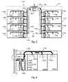
Telle qu'illustrée à la
Un réseau d'extraction d'air individuel 16h, associé à un logement 14h, est représenté à la
L'air extrait des différentes pièces 24h1, 24h2, 24h3 est amenée par le réseau d'extraction d'air individuel 16h à traverser un filtre 26h puis dans un évaporateur 28h des moyens d'échange de chaleur 18h. Le filtre 26h assure une protection de l'évaporateur 28h contre un encrassement prématuré.The air extracted from the different rooms 24h 1 , 24h 2 , 24h 3 is brought by the individual
Les moyens d'échange de chaleur 18h fonctionnent selon le principe de la pompe à chaleur. Dans l'évaporateur 28h, l'air extrait perd des calories en faveur d'un fluide frigorigène circulant dans un circuit de fluide frigorigène 30h Après avoir traversé l'évaporateur 28h, le fluide frigorigène est amené au niveau d'un compresseur 32h qui permet à la fois la mise en circulation du fluide frigorigène et la compression de ce fluide frigorigène. Cette compression du fluide frigorigène permet d'augmenter la température du fluide frigorigène. Le fluide frigorigène circule alors jusqu'à un condenseur 34h permettant l'échange de calories entre le fluide frigorigène et l'eau contenue dans le réservoir de stockage 20h afin de chauffer cette dernière. Pour permettre l'échange de calories, le condenseur 34h peut être plongé dans le réservoir de stockage, ce qui maximise la surface d'échange entre le condenseur et l'eau à chauffer. En variante, le condenseur 34h peut entourer le réservoir de stockage, en étant en contact avec une paroi externe du réservoir de stockage 20h.The heat exchange means 18h operate according to the principle of the heat pump. In the
Le fluide frigorigène circule ensuite jusqu'à un détendeur 36h avant de traverser à nouveau l'évaporateur et, ainsi, commencer un nouveau cycle.The refrigerant then flows to an
L'air extrait des différentes pièces 24h1, 24h2, 24h3, après avoir traversé l'évaporateur 28h est guidé vers un réseau d'extraction d'air commun 38 de l'installation 10. Ce réseau d'extraction d'air commun 38 est commun aux différents logements individuels 14a-14h. Le réseau d'extraction d'air commun 38 est situé en aval des moyens d'échange de chaleur 18a-18h, dans le sens du débit d'air extrait. Le réseau d'extraction d'air commun 38 comprend en l'espèce deux branches distinctes 401, 402 en communication de fluide avec un ventilateur d'extraction d'air commun 42 adapté à créer un débit d'air extrait dans le réseau d'extraction 44 formé par les réseaux d'extraction d'air individuels 16a-16h et le réseau d'extraction d'air commun 38.The air extracted from the various rooms 24h 1 , 24h 2 , 24h 3 , after having passed through the
L'installation 10 comporte encore deux capteurs de pression 46, 48 dont les prises de pression respectives 50, 52 sont disposées au niveau du débouché, dans le réseau d'extraction d'air commun 38, des réseaux d'extraction d'air individuels 14d, 14h respectivement. Les capteurs de pression 46, 48 sont ainsi adaptés à mesurer, chacun, la pression en un point du réseau d'extraction d'air commun 38. De préférence, les points du réseaux d'extraction d'air où la pression est mesurée sont choisis comme étant ceux qui correspondent à la plus grande perte de charge dans chacune des deux branches 401, 402 du réseau d'extraction d'air commun 38, par rapport au ventilateur d'extraction d'air commun 42. Les capteurs de pression sont ainsi adaptés à mesurer la pression en des points du réseau d'extraction d'air commun 38 qui sont les plus défavorisés quant à la fourniture d'une pression et d'un débit d'air d'extraction par le ventilateur d'extraction d'air commun 42.The installation 10 further comprises two
Dans toute la description, le terme « pression » est utilisé pour décrire une dépression.Throughout the description, the term "pressure" is used to describe a depression.
Comme cela est particulièrement visible sur la
La régulation peut consister, par exemple, à assurer le besoin en pression au niveau des prises de pression 50, 52 des capteurs de pression 46, 48. Dans ce cas, les prises de pression étant dans le réseau commun, et donc en aval des réseaux individuel, le besoin en pression peut tenir compte d'une estimation de la perte de charge du ou des réseaux individuels, cette estimation incluant notamment les pertes de charge dues au filtre, en fonction des débits qui peuvent être nécessaires dans le ou les réseaux d'extraction individuels. Pour compenser l'encrassement progressif des filtres présents dans les réseaux d'extraction d'air individuels, il peut être prévu une augmentation progressive de la consigne du ventilateur d'extraction d'air commun avec le temps.The regulation may consist, for example, in ensuring the pressure requirement at the pressure taps 50, 52 of the
Dans ce cas, les capteurs de pression 46, 48 peuvent être des capteurs binaires (ou logiques, par opposition à des capteurs analogiques ou numériques dont le signal de sortie peut prendre une infinité de valeurs continues ou discrètes), notamment des pressostats ou des dépressostats. Le signal de sortie de tels capteurs ne varie qu'entre deux valeurs. La première valeur (ci-après FAUX) correspond à une pression (en fait une dépression) mesurée inférieure à une valeur de seuil du capteur prédéterminée. La deuxième valeur (ci-après VRAI) correspond à une pression (en fait une dépression) mesurée supérieure à la valeur de seuil du capteur prédéterminée.In this case, the
La régulation de l'installation peut alors être réalisée de la manière suivante : les signaux de sortie des deux capteurs de pression 46, 48 sont initialement à leur valeur VRAI, c'est-à-dire qu'ils mesurent une pression supérieure à la valeur de seuil prédéterminée permettant d'assurer une extraction d'air satisfaisante dans les différents logements14a-14h de l'habitation collective 12. Le ventilateur d'extraction d'air commun fournie alors une pression initiale satisfaisante.The regulation of the installation can then be carried out as follows: the output signals of the two
Du fait d'une modification dans le réseau d'extraction 44 (par exemple, une demande de débit plus importante dans un autre logement moins défavorisé), le capteur de pression 46 ne mesure plus une pression supérieure à la valeur de seuil prédéterminée. L'unité de commande 54 reçoit alors la valeur FAUX de ce capteur. L'unité de commande 54 commande en conséquence une augmentation de la pression fournie par le ventilateur d'extraction d'air commun 42 à une valeur augmentée. L'augmentation de pression peut être prédéterminée. Après un intervalle de temps prédéterminé, il est vérifié si le signal de sortie du capteur 46 est repassé la valeur VRAI. Si ce n'est pas le cas, l'unité de commande 54 commande une nouvelle augmentation de pression du ventilateur d'extraction d'air commun 42, et cela jusqu'à ce que le signal de sortie du capteur de pression 46 repasse à sa valeur VRAI.Due to a modification in the extraction network 44 (for example, a higher flow demand in another less disadvantaged housing), the
Un fois qu'il est déterminé que le signal de sortie du capteur de pression 46 est repassé à sa valeur VRAI, l'unité de commande peut commander une diminution de la pression du ventilateur d'extraction d'air commun 42. Cette commande vise à limiter la fourniture de pression du ventilateur d'extraction d'air commun à sa valeur minimale effectivement nécessaire. La diminution de pression peut par exemple être très lente et continue jusqu'au changement d'état des capteurs 46, 48. Selon un autre exemple, la diminution de pression peut correspondre à la demi différence entre la pression initiale et la pression augmentée fournies par le ventilateur d'extraction d'air commun. On peut ainsi, par dichotomies successives, assurer la régulation du ventilateur d'extraction d'air commun de telle sorte que ce ventilateur d'extraction d'air commun fournisse le juste besoin en pression à l'installation, sans surconsommation énergétique ou nuisance sonore superflue.Once it is determined that the output signal of the
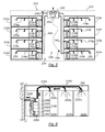
Les
Dans ces figures, les éléments identiques ou de fonction identique aux éléments décrits en regard des
Le deuxième 110 exemple d'installation de production d'eau chaude sanitaire pour une habitation collective se distingue du premier exemple 10 des
Tel que cela ressort des
Les capteurs de pression 146, 148 sont ainsi, dans ce deuxième exemple d'installation 110 de production d'eau chaude sanitaire pour une habitation collective, adaptés à mesurer la pression dans un réseau d'extraction d'air individuel. Plus précisément, ces capteurs de pression 146, 148 sont adaptés à mesurer la pression dans le réseau d'extraction d'air individuel associé, en amont du filtre 126d, 126h. Les capteurs de pression 146, 148 sont ainsi adaptés à détecter un encrassement du filtre 126d, 126h, lequel encrassement se traduisant par une chute de la dépression en amont du filtre.The
Par suite, jusqu'à une limite prédéterminée de puissance fournie par le ventilateur d'extraction d'air commun 142, l'unité de commande 154 régule le ventilateur d'extraction d'air commun 142 en adaptant la consigne de fonctionnement du ventilateur d'extraction d'air commun pour compenser l'encrassement des filtres 126d, 126h, mais aussi pour s'adapter au juste besoin en pression de l'installation 110.As a result, up to a predetermined power limit provided by the common
La limite prédéterminée de puissance fournie par le ventilateur d'extraction d'air commun peut notamment être définie en fonction :
- de la puissance maximale que peut fournir le ventilateur d'extraction d'air commun ; ou
- d'une limite de niveau sonore du ventilateur d'extraction d'air commun.
- the maximum power that can be provided by the common air exhaust fan; or
- a sound level limit of the common air exhaust fan.
Les prises de pression 150, 152 des capteurs de pression 146, 148 sont en outre ménagées en aval de toutes les bouches d'extraction 122d1, 122d2, 122h1, 122h2, 122h3 des réseaux d'extraction d'air individuels 116d, 116h dans lesquels elles sont disposées.The pressure taps 150, 152 of the
De préférence, les réseaux d'extraction d'air individuel 116d, 116h dans lesquels les prises de pression des capteurs de pression sont ménagées, débouchent dans le réseau d'extraction d'air commun 138 en des points correspondant aux pertes de charges les plus importantes vis-à-vis du ventilateur d'extraction d'air commun 142. En d'autres termes, ces réseaux d'extraction d'air individuels sont les réseaux d'extraction d'air individuels les plus défavorisés quant à la fourniture d'une dépression par le ventilateur d'extraction d'air commun 142. Ceci est particulièrement avantageux car il est possible de réguler le ventilateur d'extraction d'air commun 142 en fonction de la pression mesurée par ces seuls capteurs. En effet, si ces capteurs indiquent une pression satisfaisante, comme ils sont positionnés aux points du réseau d'extraction d'air commun les plus défavorisés, il peut être assuré que le ventilateur d'extraction d'air commun 142 fournit une pression satisfaisante à tous les réseaux d'extraction d'air commun.Preferably, the individual
Les capteurs de pressions peuvent là encore être des capteurs de pression binaires, notamment des pressostats. Dans ce cas, la régulation fonctionne sensiblement comme cela a été décrit dans le cas de l'installation 10 des
En outre, en période stabilisée, la consigne du ventilateur d'extraction d'air commun 142 peut être du type à pression constante ou à vitesse constante. Dans le cas d'une régulation à pression constante, la pression est mesurée alors par un capteur dont la prise de pression est positionnée au sein du ventilateur 142, au niveau du débouché des branches 1401 et 1402 du réseau commun. Le capteur mis en oeuvre pour ce faire peut être un capteur analogique ou numérique, dont le signal de sortie peut prendre une pluralité d'au moins trois valeurs continues ou discrètes. La période stabilisée est limitée dans le temps par une temporisation et/ou la détection d'un changement de la valeur de sortie d'un des capteurs de pression du type pressostat.In addition, in a stabilized period, the set point of the common
Les
Dans ces figures, les éléments identiques ou de fonction identique aux éléments décrits en regard des
Le troisième exemple 210 d'installation de production d'eau chaude sanitaire pour une habitation collective se distingue des premier 10 et deuxième 110 exemples des
Tel que cela ressort des
Il est à noter que la bouche la plus défavorisée peut varier en fonction du temps. Dans ce cas, il est intéressant de mesurer la pression au niveau de toutes les bouches susceptibles d'être, à un instant donné, la bouche la plus défavorisée de l'installation 210. En effet, en assurant une pression satisfaisante au niveau de cette bouche la plus défavorisée de l'installation, on s'assure qu'une dépression satisfaisante règne au niveau de toutes les bouches d'extraction de tous les réseaux d'extraction d'air individuels.It should be noted that the most underprivileged mouth may vary with time. In this case, it is interesting to measure the pressure at all the mouths likely to be at a given moment, the most disadvantaged mouth of the
Il est particulièrement intéressant d'utiliser comme capteurs 46, 48, 146, 148, 246, 248 des dépressostats, c'est-à-dire des capteurs de pression binaires ou logiques, qui se comportent comme des contacts fermés quand la dépression qu'ils mesurent est supérieure à une valeur de seuil prédéterminée, et comme des contacts ouverts quand la dépression qu'ils mesurent est inférieure à cette valeur de seuil prédéterminée.It is particularly advantageous to use as
En effet, il est alors possible de relier électriquement ces différents capteurs à l'unité de commande par un montage en série des capteurs. D'autres capteurs, comme des capteurs analogiques ou numériques dont le signal de sortie peut prendre au moins trois valeurs différentes continues ou discrètes, nécessiteraient a priori des câblages séparés des différents capteurs de pression et une analyse individuelle du signal de sortie de chaque capteur de pression.Indeed, it is then possible to electrically connect these different sensors to the control unit by a series connection of the sensors. Other sensors, such as analog or digital sensors whose output signal can take at least three different continuous or discrete values, would in principle require separate cabling of the different pressure sensors and an individual analysis of the output signal of each sensor. pressure.
Avec des dépressostats, qui sont des capteurs logiques, dès que la dépression mesurée par l'un des capteurs de pression devient inférieure à la valeur de seuil prédéterminée, alors le signal reçu par l'unité de commande est nul puisque le circuit formé par le câblage des capteurs de pression en série est ouvert. L'unité de commande peut alors commander une augmentation de la dépression fournie par le ventilateur d'extraction d'air commun puisque la dépression est insuffisante au niveau d'au moins une bouche d'extraction. La régulation commandée par l'unité de commande est alors similaire à la régulation décrite en regard des
Le câblage en série des différents capteurs logiques limite également les risques de problèmes de compatibilité électromagnétique en comparaison avec des capteurs analogiques ou numériques.The serial wiring of the different logic sensors also limits the risks of electromagnetic compatibility problems compared to analog or digital sensors.
Bien entendu, les dépressostats mis en oeuvre pourraient également se comporter comme un contact fermé quand la dépression qu'ils mesurent est inférieure à la valeur de seuil déterminée, et comme un contact ouvert quand la dépression qu'ils mesurent est supérieure à la valeur de seuil prédéterminée. Dans ce cas, cependant, pour pouvoir réguler de manière efficace l'installation, il conviendrait de relier les différents dépressostats à l'unité de commande en parallèle les uns des autres.Of course, the depressostats used could also behave as a closed contact when the depression they measure is less than the determined threshold value, and as an open contact when the depression they measure is greater than the value of predetermined threshold. In this case, however, in order to effectively regulate the installation, it would be necessary to connect the different depressostats to the control unit in parallel with each other.
En variante, les capteurs de pression mis en oeuvre peuvent communiquer avec l'unité de commande par ondes radiofréquences ou par courant porteur.As a variant, the pressure sensors used may communicate with the control unit by radiofrequency waves or by a carrier current.
Bien entendu, la présente invention n'est pas limitée aux exemples et au mode de réalisation décrits et représentés, mais elle est susceptible de nombreuses variantes accessibles à l'homme de l'art.Of course, the present invention is not limited to the examples and to the embodiment described and shown, but it is capable of numerous variants accessible to those skilled in the art.
Claims (10)
Applications Claiming Priority (1)
| Application Number | Priority Date | Filing Date | Title |
|---|---|---|---|
| FR1058754A FR2966564A1 (en) | 2010-10-25 | 2010-10-25 | HOT WATER PRODUCTION FACILITY FOR COLLECTIVE HOUSING COMPRISING A COMMON AIR EXTRACTION FAN |
Publications (2)
| Publication Number | Publication Date |
|---|---|
| EP2444748A1 true EP2444748A1 (en) | 2012-04-25 |
| EP2444748B1 EP2444748B1 (en) | 2014-12-17 |
Family
ID=44083816
Family Applications (1)
| Application Number | Title | Priority Date | Filing Date |
|---|---|---|---|
| EP11185856.9A Active EP2444748B1 (en) | 2010-10-25 | 2011-10-19 | Facility for producing domestic hot water for an apartment block including a common air-extractor fan |
Country Status (3)
| Country | Link |
|---|---|
| EP (1) | EP2444748B1 (en) |
| ES (1) | ES2532739T3 (en) |
| FR (1) | FR2966564A1 (en) |
Cited By (4)
| Publication number | Priority date | Publication date | Assignee | Title |
|---|---|---|---|---|
| FR3020446A1 (en) * | 2014-04-24 | 2015-10-30 | Atlantic Climatisation & Ventilation | VENTILATION INSTALLATION OF A SET OF HOUSING WITH A THERMODYNAMIC WATER HEATER |
| EP3091305A1 (en) * | 2015-05-07 | 2016-11-09 | Atlantic Climatisation et Ventilation | Thermodynamic water heater |
| EP3118529A1 (en) * | 2015-07-16 | 2017-01-18 | Atlantic Climatisation et Ventilation | System for heating and hot-water production in a dwelling |
| FR3061762A1 (en) * | 2017-01-11 | 2018-07-13 | Vti | METHOD FOR CONTROLLING THE ROTATION SPEED OF A VICIE AIR EXTRACTION FAN |
Citations (5)
| Publication number | Priority date | Publication date | Assignee | Title |
|---|---|---|---|---|
| DE3022931A1 (en) * | 1980-06-19 | 1982-01-07 | Ventiheat Ltd., Kolding | Heating system utilising waste heat from barn - has heat pump with evaporator and condenser within water tank which feeds radiator in house |
| JPS6071829A (en) * | 1983-09-29 | 1985-04-23 | Nippon P-Mc Kk | Device making use of air in bath room |
| JPS61168744A (en) * | 1985-01-23 | 1986-07-30 | Matsushita Electric Ind Co Ltd | Hot water supply system utilizing heat pump |
| DE19614913A1 (en) * | 1996-04-16 | 1997-10-23 | Reinl Manfred | House-ventilation system with heat-recovery by heat-pump |
| FR2926626A1 (en) | 2008-01-22 | 2009-07-24 | Aldes Aeraulique Sa | HOT WATER PRODUCTION FACILITY FOR COLLECTIVE HOUSING |
-
2010
- 2010-10-25 FR FR1058754A patent/FR2966564A1/en not_active Withdrawn
-
2011
- 2011-10-19 ES ES11185856.9T patent/ES2532739T3/en active Active
- 2011-10-19 EP EP11185856.9A patent/EP2444748B1/en active Active
Patent Citations (5)
| Publication number | Priority date | Publication date | Assignee | Title |
|---|---|---|---|---|
| DE3022931A1 (en) * | 1980-06-19 | 1982-01-07 | Ventiheat Ltd., Kolding | Heating system utilising waste heat from barn - has heat pump with evaporator and condenser within water tank which feeds radiator in house |
| JPS6071829A (en) * | 1983-09-29 | 1985-04-23 | Nippon P-Mc Kk | Device making use of air in bath room |
| JPS61168744A (en) * | 1985-01-23 | 1986-07-30 | Matsushita Electric Ind Co Ltd | Hot water supply system utilizing heat pump |
| DE19614913A1 (en) * | 1996-04-16 | 1997-10-23 | Reinl Manfred | House-ventilation system with heat-recovery by heat-pump |
| FR2926626A1 (en) | 2008-01-22 | 2009-07-24 | Aldes Aeraulique Sa | HOT WATER PRODUCTION FACILITY FOR COLLECTIVE HOUSING |
Cited By (7)
| Publication number | Priority date | Publication date | Assignee | Title |
|---|---|---|---|---|
| FR3020446A1 (en) * | 2014-04-24 | 2015-10-30 | Atlantic Climatisation & Ventilation | VENTILATION INSTALLATION OF A SET OF HOUSING WITH A THERMODYNAMIC WATER HEATER |
| EP3091305A1 (en) * | 2015-05-07 | 2016-11-09 | Atlantic Climatisation et Ventilation | Thermodynamic water heater |
| FR3035954A1 (en) * | 2015-05-07 | 2016-11-11 | Atlantic Climatisation & Ventilation | THERMODYNAMIC WATER HEATER |
| EP3118529A1 (en) * | 2015-07-16 | 2017-01-18 | Atlantic Climatisation et Ventilation | System for heating and hot-water production in a dwelling |
| FR3038967A1 (en) * | 2015-07-16 | 2017-01-20 | Atlantic Climatisation & Ventilation | SYSTEM FOR HEATING AND PRODUCTION OF HOT WATER IN A HOUSE |
| FR3061762A1 (en) * | 2017-01-11 | 2018-07-13 | Vti | METHOD FOR CONTROLLING THE ROTATION SPEED OF A VICIE AIR EXTRACTION FAN |
| EP3348922A1 (en) * | 2017-01-11 | 2018-07-18 | Vti | Control of the rotational speed of an extraction blower |
Also Published As
| Publication number | Publication date |
|---|---|
| EP2444748B1 (en) | 2014-12-17 |
| ES2532739T3 (en) | 2015-03-31 |
| FR2966564A1 (en) | 2012-04-27 |
Similar Documents
| Publication | Publication Date | Title |
|---|---|---|
| EP1957889B1 (en) | Heat pump for heating swimming pool water | |
| EP2444748B1 (en) | Facility for producing domestic hot water for an apartment block including a common air-extractor fan | |
| EP2312227B1 (en) | Controlled mechanical ventilation device of the type with reversible double thermodynamic flow with domestic hot water production | |
| FR3041420B1 (en) | HOT WATER PRODUCTION DEVICE USING WASTEWATER HEAT RECOVERY, AN INSTALLATION AND A PROCESS FOR THE PRODUCTION THEREOF | |
| EP3213004A1 (en) | Hub for the modulated distribution of fresh air | |
| EP2444747B1 (en) | Device for producing domestic hot water for an apartment block and method for controlling such a device | |
| EP1987292B1 (en) | Heat exchanger device intended for heating or air-conditioning systems | |
| BE1022374B1 (en) | Installation of ventilation and production of domestic hot water for collective housing | |
| EP2775221A1 (en) | Regulation of the flow and temperature of a sanitary hot water circulator | |
| FR2966563A1 (en) | System for producing domestic hot water in apartment building, has air extraction network common to individual housings, in which individual air extraction networks open, where common network is provided with common air exhaust fan | |
| FR2997756A1 (en) | DEVICE FOR HYBRID HEATING OF A FLUID OF A BASIN | |
| FR3018902A1 (en) | HOT WATER PRODUCTION FACILITY AND METHOD FOR CONTROLLING THIS INSTALLATION | |
| FR2984997A1 (en) | Installation for treatment of air in building e.g. office, has thermodynamic water-heater, where calorific energy is extracted from air, and water-heater is connected to storage balloon for providing pre-heated water to building | |
| FR2468851A1 (en) | METHOD AND DEVICE FOR HEATING WATER USED IN AN APPARATUS CONNECTED TO A DOMESTIC WATER CIRCUIT | |
| EP3091305B1 (en) | Thermodynamic water heater | |
| FR2913755A1 (en) | Ventilation device for heat regulation system of e.g. dwelling, has turbine mounted in cylindrical case and comprising rotation shaft integrated to ventilation unit, where turbine is rotated by circulation of heat transfer fluid in case | |
| FR3088990A1 (en) | Heating system | |
| FR3063800A3 (en) | PERFECTIONAL HYDRAULIC SATELLITE GROUP | |
| BE1022750B1 (en) | Ventilation installation of a housing unit equipped with a thermodynamic water heater | |
| EP3273170A1 (en) | Installation for producing hot water with a thermodynamic circuit powered by photovoltaic cells | |
| FR3023359A1 (en) | BUILDING EQUIPPED WITH A THERMODYNAMIC WATER HEATER, A CONTROLLED MECHANICAL VENTILATION SYSTEM AND ONE OR MORE AUXILIARY SOURCES, AND METHOD OF REGULATING THE THERMODYNAMIC WATER HEATER | |
| WO1995008083A1 (en) | Domestic hot water heating system | |
| BE1022750A1 (en) | Ventilation installation of a housing unit equipped with a thermodynamic water heater | |
| FR2913757A1 (en) | DEVICE FOR COUPLING A HEAT PUMP HEATING SYSTEM TO A COOLING DEVICE | |
| EP3660415A1 (en) | Apparatus for thermal control of a building, associated installation and method |
Legal Events
| Date | Code | Title | Description |
|---|---|---|---|
| AK | Designated contracting states |
Kind code of ref document: A1 Designated state(s): AL AT BE BG CH CY CZ DE DK EE ES FI FR GB GR HR HU IE IS IT LI LT LU LV MC MK MT NL NO PL PT RO RS SE SI SK SM TR |
|
| AX | Request for extension of the european patent |
Extension state: BA ME |
|
| PUAI | Public reference made under article 153(3) epc to a published international application that has entered the european phase |
Free format text: ORIGINAL CODE: 0009012 |
|
| 17P | Request for examination filed |
Effective date: 20121025 |
|
| RIC1 | Information provided on ipc code assigned before grant |
Ipc: F24D 17/02 20060101ALI20140529BHEP Ipc: F24D 11/02 20060101AFI20140529BHEP |
|
| GRAP | Despatch of communication of intention to grant a patent |
Free format text: ORIGINAL CODE: EPIDOSNIGR1 |
|
| INTG | Intention to grant announced |
Effective date: 20140704 |
|
| GRAS | Grant fee paid |
Free format text: ORIGINAL CODE: EPIDOSNIGR3 |
|
| GRAA | (expected) grant |
Free format text: ORIGINAL CODE: 0009210 |
|
| AK | Designated contracting states |
Kind code of ref document: B1 Designated state(s): AL AT BE BG CH CY CZ DE DK EE ES FI FR GB GR HR HU IE IS IT LI LT LU LV MC MK MT NL NO PL PT RO RS SE SI SK SM TR |
|
| REG | Reference to a national code |
Ref country code: GB Ref legal event code: FG4D Free format text: NOT ENGLISH |
|
| REG | Reference to a national code |
Ref country code: CH Ref legal event code: EP |
|
| REG | Reference to a national code |
Ref country code: IE Ref legal event code: FG4D Free format text: LANGUAGE OF EP DOCUMENT: FRENCH |
|
| REG | Reference to a national code |
Ref country code: AT Ref legal event code: REF Ref document number: 702209 Country of ref document: AT Kind code of ref document: T Effective date: 20150115 |
|
| REG | Reference to a national code |
Ref country code: DE Ref legal event code: R096 Ref document number: 602011012254 Country of ref document: DE Effective date: 20150129 |
|
| REG | Reference to a national code |
Ref country code: CH Ref legal event code: NV Representative=s name: WEINMANN ZIMMERLI, CH Ref country code: ES Ref legal event code: FG2A Ref document number: 2532739 Country of ref document: ES Kind code of ref document: T3 Effective date: 20150331 |
|
| PG25 | Lapsed in a contracting state [announced via postgrant information from national office to epo] |
Ref country code: FI Free format text: LAPSE BECAUSE OF FAILURE TO SUBMIT A TRANSLATION OF THE DESCRIPTION OR TO PAY THE FEE WITHIN THE PRESCRIBED TIME-LIMIT Effective date: 20141217 Ref country code: NO Free format text: LAPSE BECAUSE OF FAILURE TO SUBMIT A TRANSLATION OF THE DESCRIPTION OR TO PAY THE FEE WITHIN THE PRESCRIBED TIME-LIMIT Effective date: 20150317 Ref country code: LT Free format text: LAPSE BECAUSE OF FAILURE TO SUBMIT A TRANSLATION OF THE DESCRIPTION OR TO PAY THE FEE WITHIN THE PRESCRIBED TIME-LIMIT Effective date: 20141217 |
|
| REG | Reference to a national code |
Ref country code: LT Ref legal event code: MG4D |
|
| PG25 | Lapsed in a contracting state [announced via postgrant information from national office to epo] |
Ref country code: SE Free format text: LAPSE BECAUSE OF FAILURE TO SUBMIT A TRANSLATION OF THE DESCRIPTION OR TO PAY THE FEE WITHIN THE PRESCRIBED TIME-LIMIT Effective date: 20141217 Ref country code: RS Free format text: LAPSE BECAUSE OF FAILURE TO SUBMIT A TRANSLATION OF THE DESCRIPTION OR TO PAY THE FEE WITHIN THE PRESCRIBED TIME-LIMIT Effective date: 20141217 Ref country code: GR Free format text: LAPSE BECAUSE OF FAILURE TO SUBMIT A TRANSLATION OF THE DESCRIPTION OR TO PAY THE FEE WITHIN THE PRESCRIBED TIME-LIMIT Effective date: 20150318 Ref country code: HR Free format text: LAPSE BECAUSE OF FAILURE TO SUBMIT A TRANSLATION OF THE DESCRIPTION OR TO PAY THE FEE WITHIN THE PRESCRIBED TIME-LIMIT Effective date: 20141217 Ref country code: LV Free format text: LAPSE BECAUSE OF FAILURE TO SUBMIT A TRANSLATION OF THE DESCRIPTION OR TO PAY THE FEE WITHIN THE PRESCRIBED TIME-LIMIT Effective date: 20141217 |
|
| REG | Reference to a national code |
Ref country code: AT Ref legal event code: MK05 Ref document number: 702209 Country of ref document: AT Kind code of ref document: T Effective date: 20141217 |
|
| PG25 | Lapsed in a contracting state [announced via postgrant information from national office to epo] |
Ref country code: NL Free format text: LAPSE BECAUSE OF FAILURE TO SUBMIT A TRANSLATION OF THE DESCRIPTION OR TO PAY THE FEE WITHIN THE PRESCRIBED TIME-LIMIT Effective date: 20141217 |
|
| REG | Reference to a national code |
Ref country code: DE Ref legal event code: R082 Ref document number: 602011012254 Country of ref document: DE |
|
| PG25 | Lapsed in a contracting state [announced via postgrant information from national office to epo] |
Ref country code: EE Free format text: LAPSE BECAUSE OF FAILURE TO SUBMIT A TRANSLATION OF THE DESCRIPTION OR TO PAY THE FEE WITHIN THE PRESCRIBED TIME-LIMIT Effective date: 20141217 Ref country code: CZ Free format text: LAPSE BECAUSE OF FAILURE TO SUBMIT A TRANSLATION OF THE DESCRIPTION OR TO PAY THE FEE WITHIN THE PRESCRIBED TIME-LIMIT Effective date: 20141217 Ref country code: RO Free format text: LAPSE BECAUSE OF FAILURE TO SUBMIT A TRANSLATION OF THE DESCRIPTION OR TO PAY THE FEE WITHIN THE PRESCRIBED TIME-LIMIT Effective date: 20141217 Ref country code: SK Free format text: LAPSE BECAUSE OF FAILURE TO SUBMIT A TRANSLATION OF THE DESCRIPTION OR TO PAY THE FEE WITHIN THE PRESCRIBED TIME-LIMIT Effective date: 20141217 |
|
| PG25 | Lapsed in a contracting state [announced via postgrant information from national office to epo] |
Ref country code: IS Free format text: LAPSE BECAUSE OF FAILURE TO SUBMIT A TRANSLATION OF THE DESCRIPTION OR TO PAY THE FEE WITHIN THE PRESCRIBED TIME-LIMIT Effective date: 20150417 Ref country code: AT Free format text: LAPSE BECAUSE OF FAILURE TO SUBMIT A TRANSLATION OF THE DESCRIPTION OR TO PAY THE FEE WITHIN THE PRESCRIBED TIME-LIMIT Effective date: 20141217 Ref country code: PL Free format text: LAPSE BECAUSE OF FAILURE TO SUBMIT A TRANSLATION OF THE DESCRIPTION OR TO PAY THE FEE WITHIN THE PRESCRIBED TIME-LIMIT Effective date: 20141217 |
|
| REG | Reference to a national code |
Ref country code: DE Ref legal event code: R097 Ref document number: 602011012254 Country of ref document: DE |
|
| PLBE | No opposition filed within time limit |
Free format text: ORIGINAL CODE: 0009261 |
|
| REG | Reference to a national code |
Ref country code: FR Ref legal event code: PLFP Year of fee payment: 5 |
|
| STAA | Information on the status of an ep patent application or granted ep patent |
Free format text: STATUS: NO OPPOSITION FILED WITHIN TIME LIMIT |
|
| PG25 | Lapsed in a contracting state [announced via postgrant information from national office to epo] |
Ref country code: DK Free format text: LAPSE BECAUSE OF FAILURE TO SUBMIT A TRANSLATION OF THE DESCRIPTION OR TO PAY THE FEE WITHIN THE PRESCRIBED TIME-LIMIT Effective date: 20141217 |
|
| 26N | No opposition filed |
Effective date: 20150918 |
|
| PG25 | Lapsed in a contracting state [announced via postgrant information from national office to epo] |
Ref country code: IT Free format text: LAPSE BECAUSE OF FAILURE TO SUBMIT A TRANSLATION OF THE DESCRIPTION OR TO PAY THE FEE WITHIN THE PRESCRIBED TIME-LIMIT Effective date: 20141217 |
|
| PG25 | Lapsed in a contracting state [announced via postgrant information from national office to epo] |
Ref country code: SI Free format text: LAPSE BECAUSE OF FAILURE TO SUBMIT A TRANSLATION OF THE DESCRIPTION OR TO PAY THE FEE WITHIN THE PRESCRIBED TIME-LIMIT Effective date: 20141217 |
|
| PG25 | Lapsed in a contracting state [announced via postgrant information from national office to epo] |
Ref country code: LU Free format text: LAPSE BECAUSE OF FAILURE TO SUBMIT A TRANSLATION OF THE DESCRIPTION OR TO PAY THE FEE WITHIN THE PRESCRIBED TIME-LIMIT Effective date: 20151019 |
|
| PG25 | Lapsed in a contracting state [announced via postgrant information from national office to epo] |
Ref country code: MC Free format text: LAPSE BECAUSE OF FAILURE TO SUBMIT A TRANSLATION OF THE DESCRIPTION OR TO PAY THE FEE WITHIN THE PRESCRIBED TIME-LIMIT Effective date: 20141217 |
|
| REG | Reference to a national code |
Ref country code: IE Ref legal event code: MM4A |
|
| REG | Reference to a national code |
Ref country code: FR Ref legal event code: PLFP Year of fee payment: 6 |
|
| PG25 | Lapsed in a contracting state [announced via postgrant information from national office to epo] |
Ref country code: IE Free format text: LAPSE BECAUSE OF NON-PAYMENT OF DUE FEES Effective date: 20151019 |
|
| PG25 | Lapsed in a contracting state [announced via postgrant information from national office to epo] |
Ref country code: HU Free format text: LAPSE BECAUSE OF FAILURE TO SUBMIT A TRANSLATION OF THE DESCRIPTION OR TO PAY THE FEE WITHIN THE PRESCRIBED TIME-LIMIT; INVALID AB INITIO Effective date: 20111019 Ref country code: SM Free format text: LAPSE BECAUSE OF FAILURE TO SUBMIT A TRANSLATION OF THE DESCRIPTION OR TO PAY THE FEE WITHIN THE PRESCRIBED TIME-LIMIT Effective date: 20141217 Ref country code: BG Free format text: LAPSE BECAUSE OF FAILURE TO SUBMIT A TRANSLATION OF THE DESCRIPTION OR TO PAY THE FEE WITHIN THE PRESCRIBED TIME-LIMIT Effective date: 20141217 |
|
| PG25 | Lapsed in a contracting state [announced via postgrant information from national office to epo] |
Ref country code: CY Free format text: LAPSE BECAUSE OF FAILURE TO SUBMIT A TRANSLATION OF THE DESCRIPTION OR TO PAY THE FEE WITHIN THE PRESCRIBED TIME-LIMIT Effective date: 20141217 |
|
| PG25 | Lapsed in a contracting state [announced via postgrant information from national office to epo] |
Ref country code: MT Free format text: LAPSE BECAUSE OF FAILURE TO SUBMIT A TRANSLATION OF THE DESCRIPTION OR TO PAY THE FEE WITHIN THE PRESCRIBED TIME-LIMIT Effective date: 20141217 Ref country code: TR Free format text: LAPSE BECAUSE OF FAILURE TO SUBMIT A TRANSLATION OF THE DESCRIPTION OR TO PAY THE FEE WITHIN THE PRESCRIBED TIME-LIMIT Effective date: 20141217 |
|
| REG | Reference to a national code |
Ref country code: FR Ref legal event code: PLFP Year of fee payment: 7 |
|
| PGFP | Annual fee paid to national office [announced via postgrant information from national office to epo] |
Ref country code: DE Payment date: 20171019 Year of fee payment: 7 |
|
| PGFP | Annual fee paid to national office [announced via postgrant information from national office to epo] |
Ref country code: ES Payment date: 20171121 Year of fee payment: 7 Ref country code: GB Payment date: 20171019 Year of fee payment: 7 Ref country code: CH Payment date: 20171019 Year of fee payment: 7 |
|
| PG25 | Lapsed in a contracting state [announced via postgrant information from national office to epo] |
Ref country code: MK Free format text: LAPSE BECAUSE OF FAILURE TO SUBMIT A TRANSLATION OF THE DESCRIPTION OR TO PAY THE FEE WITHIN THE PRESCRIBED TIME-LIMIT Effective date: 20141217 |
|
| PG25 | Lapsed in a contracting state [announced via postgrant information from national office to epo] |
Ref country code: PT Free format text: LAPSE BECAUSE OF FAILURE TO SUBMIT A TRANSLATION OF THE DESCRIPTION OR TO PAY THE FEE WITHIN THE PRESCRIBED TIME-LIMIT Effective date: 20141217 |
|
| REG | Reference to a national code |
Ref country code: FR Ref legal event code: PLFP Year of fee payment: 8 |
|
| PG25 | Lapsed in a contracting state [announced via postgrant information from national office to epo] |
Ref country code: AL Free format text: LAPSE BECAUSE OF FAILURE TO SUBMIT A TRANSLATION OF THE DESCRIPTION OR TO PAY THE FEE WITHIN THE PRESCRIBED TIME-LIMIT Effective date: 20141217 |
|
| REG | Reference to a national code |
Ref country code: DE Ref legal event code: R119 Ref document number: 602011012254 Country of ref document: DE |
|
| REG | Reference to a national code |
Ref country code: CH Ref legal event code: PL |
|
| GBPC | Gb: european patent ceased through non-payment of renewal fee |
Effective date: 20181019 |
|
| PG25 | Lapsed in a contracting state [announced via postgrant information from national office to epo] |
Ref country code: DE Free format text: LAPSE BECAUSE OF NON-PAYMENT OF DUE FEES Effective date: 20190501 |
|
| PG25 | Lapsed in a contracting state [announced via postgrant information from national office to epo] |
Ref country code: LI Free format text: LAPSE BECAUSE OF NON-PAYMENT OF DUE FEES Effective date: 20181031 Ref country code: CH Free format text: LAPSE BECAUSE OF NON-PAYMENT OF DUE FEES Effective date: 20181031 |
|
| PG25 | Lapsed in a contracting state [announced via postgrant information from national office to epo] |
Ref country code: GB Free format text: LAPSE BECAUSE OF NON-PAYMENT OF DUE FEES Effective date: 20181019 |
|
| REG | Reference to a national code |
Ref country code: ES Ref legal event code: FD2A Effective date: 20191202 |
|
| PG25 | Lapsed in a contracting state [announced via postgrant information from national office to epo] |
Ref country code: ES Free format text: LAPSE BECAUSE OF NON-PAYMENT OF DUE FEES Effective date: 20181020 |
|
| REG | Reference to a national code |
Ref country code: BE Ref legal event code: HC Owner name: ATLANTIC CLIMATISATION ET TRAITEMENT D'AIR INDUSTRIE; FR Free format text: DETAILS ASSIGNMENT: CHANGE OF OWNER(S), CHANGE OF OWNER(S) NAME; FORMER OWNER NAME: ATLANTIC CLIMATISATION ET VENTILATION Effective date: 20220517 |
|
| P01 | Opt-out of the competence of the unified patent court (upc) registered |
Effective date: 20230530 |
|
| PGFP | Annual fee paid to national office [announced via postgrant information from national office to epo] |
Ref country code: FR Payment date: 20231129 Year of fee payment: 13 |
|
| PGFP | Annual fee paid to national office [announced via postgrant information from national office to epo] |
Ref country code: BE Payment date: 20231129 Year of fee payment: 13 |